EP2303086B1 - Système et procédé automatisés de nettoyage et manipulation de tapis - Google Patents
Système et procédé automatisés de nettoyage et manipulation de tapis Download PDFInfo
- Publication number
- EP2303086B1 EP2303086B1 EP09767738.9A EP09767738A EP2303086B1 EP 2303086 B1 EP2303086 B1 EP 2303086B1 EP 09767738 A EP09767738 A EP 09767738A EP 2303086 B1 EP2303086 B1 EP 2303086B1
- Authority
- EP
- European Patent Office
- Prior art keywords
- module
- mat
- conveyor
- flat object
- cleaning system
- Prior art date
- Legal status (The legal status is an assumption and is not a legal conclusion. Google has not performed a legal analysis and makes no representation as to the accuracy of the status listed.)
- Active
Links
Images








Classifications
-
- D—TEXTILES; PAPER
- D06—TREATMENT OF TEXTILES OR THE LIKE; LAUNDERING; FLEXIBLE MATERIALS NOT OTHERWISE PROVIDED FOR
- D06G—MECHANICAL OR PRESSURE CLEANING OF CARPETS, RUGS, SACKS, HIDES, OR OTHER SKIN OR TEXTILE ARTICLES OR FABRICS; TURNING INSIDE-OUT FLEXIBLE TUBULAR OR OTHER HOLLOW ARTICLES
- D06G1/00—Beating, brushing, or otherwise mechanically cleaning or pressure cleaning carpets, rugs, sacks, hides, or other skin or textile articles or fabrics
-
- D—TEXTILES; PAPER
- D06—TREATMENT OF TEXTILES OR THE LIKE; LAUNDERING; FLEXIBLE MATERIALS NOT OTHERWISE PROVIDED FOR
- D06F—LAUNDERING, DRYING, IRONING, PRESSING OR FOLDING TEXTILE ARTICLES
- D06F31/00—Washing installations comprising an assembly of several washing machines or washing units, e.g. continuous flow assemblies
Definitions
- Embodiments of the present invention relate, in general, to a mat handling assembly and a method for using the same.
- embodiments of the invention relate to a system and method for cleaning mats.
- floor mats may be used in food service, manufacturing, and health care settings to reduce leg and lower back strain, decrease incidence of injuries due to slipping and fatigue, and limit biological and chemical contamination and pest infestation.
- Conventional equipment and techniques used to clean mats may require awkward manual manipulation of the mats, which may generate back strain or other injury in workers.
- conventional cleaning systems may be wasteful of both time and energy. Due to these limitations, prior art cleaning equipment and techniques may inhibit the efficiency with which mats and screens are properly cleansed, and in some cases, conventional practices may actually degrade the sanitary quality of a work place, public area, or dwelling.
- a system and method for cleaning mats that is more energy-efficient by reducing the amount of chemicals, water, and energy used to wash and dry the mats. It may also be advantageous for a mat-cleaning system to improve worker safety by having an ergonomic design and by reducing the number of workers needed to operate the system. Furthermore, it may be advantageous if the mat-cleaning system extends the product life of the mats by reducing wear and providing an opportunity for quality control. Wear and tear on the mats may be reduced by reducing the handling of the mats and/or by lowering the water or fluid pressure when cleaning the mats.
- US 4103389 discloses a cleaning and drying machine for mats or the like having a stiff backing and a fibrous nap.
- An entry station which receives the mats upside down includes a beater roll positioned above the pass line for engaging the backside of the mat.
- a washing station receives the mats and includes two wet wash brushes, preferably operating in counterrotating directions.
- a rinse station then receives the mats and includes rinse sprays and a wringer roll assembly.
- a duct transports the mat to a drying station which is normally positioned below the rinse station and includes at least one roll assembly comprising a floating upper heated roll for engaging the nap and a lower, nonheated, preferably cooled roll for engaging the stiff backing.
- a final air blast removes the remaining moisture as the mat is removed from the machine by a belt conveyor.
- Examples described herein relate to the cleaning of rugs or mats, or other similar generally flat objects that require periodic maintenance, and more particularly to systems and methods for industrial mat cleaning. More specifically, the current application discloses a system and method for cleaning and processing mats.
- the term "mat” will refer to any flat object suitable for use in the disclosed cleaning system and by the proposed methodology, including but not limited to industrial floor mats, rugs, or other flat objects.
- the term "dirt” will refer to any debris present on or in the mat being cleaned by the system (100), including but not limited to dirt, debris, dust, or any other particles or unwanted matter. A shown in FIG.
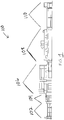
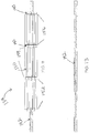
- a mat cleaning system comprises one or more modules including but not limited to a loading module (102), a vibration module (104), a washing module (106), a drying module (108), and a discharge module (110). Each mat being cleaned is directed through each module.
- a loading module 102
- a vibration module 104
- a washing module 106
- a drying module 108
- a discharge module 110
- Each mat being cleaned is directed through each module.
- vibration module (104) may come after washing module (106).
- the modules comprising mat cleaning system (100) will be discussed further below.
- FIG. 2 shows a loading module (102) of the system (100) shown in FIG. 1 .
- Loading module (102) may comprise an air-float table (112) upon which a mat can be placed.
- table (112) may be a gravity conveyor, which uses gravity to feed the mat through the module.
- the table (112) may have a first end (114) for loading the mats and a second end (116) that engages with the next module, which in the present embodiment is vibration module (104).
- table (112) may also comprise a number of features to facilitate the loading and cleaning of the mats.
- table (112) may comprise one or more load rollers (118), which may rotate to assist a user in loading a mat into the system (100). Load rollers (118) may also help straighten and/or flatten the mat as it is fed onto table (112). Although load rollers (118) are positioned near the first end (114) of table (112) in the present example, it will be appreciated that a roller (118) may be located in any other suitable location along table (112). In addition to the load rollers (118), table (112) may comprise one or more edge guides (120) located along an edge of the table (112) to help guide the loaded mat along the table (112).
- any suitable mat may be loaded into system (100).
- the dimensions of the mats that can be cleaned by the system (100) may depend on the dimensions of system (100). For example, in the present embodiment, any mat with a width up to five feet may be fed into the system (100). Larger sized mats may be loaded into other versions of system (100).
- a mat may comprise at least two surfaces, an underside and a pile side. The pile side may be the side of the mat generally exposed during use of the mat.
- the mat may be fed into system (100), and more particularly into loading module (102), in any suitable manner as will be apparent to one of ordinary skill in the art. For example, to best clean the pile side of a mat, the mat may be loaded with the pile side positioned down towards table (112).
- air-float table (112) may further comprise a plurality of apertures (122) through which air may be blown to easily and ergonomically feed the mat through the module (102) and into the next module.
- at least a portion of the surface of table (112) may also comprise a grid, screen, or gravity conveyor defining a plurality of open apertures through which dirt may fall. In this way, as a mat is loaded onto table (112), any dirt shaken from the mat during the loading process may fall through apertures (122) to be collected by a collection trough (124) that may be situated beneath table (112).
- collection trough (124) may also collect any dirt that is blown off the loaded mat by way of a blower (126), which may be situated underneath of table (112).
- Blower (126) may be directed to blow air from the underside of table (112) and through apertures (122) to dislodge the dirt on the loaded mat. Blower (126) may also be used with an air-float table (112) to assist in feeding the mat to a next module in the system.
- loading module (102) may comprise a quality control inspection, which may be performed prior to or during the loading process.
- a quality control inspection may include a review of the mat for tears, stains, worn spots, or any other quality-related issues.
- the inspection may include inspecting both sides of the entire mat.
- the inspection may only include inspecting either the pile side or the underside of the mat.
- the inspection of the pile side of the mat may occur prior to flipping the mat pile side down and feeding the mat onto table (112). Inspection of the underside portion of the mat may occur after loading the mat onto the air-float table (112) pile side down.
- a quality control inspection may also include the pretreatment of stains or spots on the mat and/or the removal of damaged mats from the system (100).
- loading module (102) is merely one example. Any other suitable type of loading module (102) and associated components may be used.
- loading module (102) may also comprise laser sights, which may be used to detect a wavy or rumpled mat that may need to be straightened before further transport through system (100).
- loading module (102) may have any other suitable components, features, configurations, functionalities, operability, etc.
- Other suitable variations of loading module (102) and associated components will be apparent to those of ordinary skill in the art in view of the teachings herein.
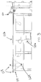
- the mat cleaning system (100) of the present example may also comprise a vibration module (104) as shown in FIG. 2 .
- the mat may be directed at the second end (116) of table (112) to the vibration module (104).
- vibration module (104) may comprise a conveyor (128) and at least one beat roller (130). After being fed through the loading module (102), the mat may be positioned onto the conveyor (128). Conveyor (128) may be used to transport the mat through system (100).
- the at least one beat roller (130) and conveyor (128) engage the mat so as to dislodge any dirt (132) that is present on or in the mat.
- a beat roller (130) may contact the mat simultaneously with or subsequent to the movement of the mat by the conveyor (128).
- the beat roller (130) may contact the mat on its underside or, alternatively, on its pile side. Having the beat roller (130) contact the mat may loosen as well as dislodge dirt from the mat.
- Conveyor (128) may not only be used to transport the mat through system (100), but may also, through an opening on the conveyor (128), permit the collection of any dirt that may be loosened or dislodged from the mat during the vibratory action caused by a beat roller (130).
- any suitable vibration frequency of module (104) may be used to shake off or dislodge the dirt from the mat.
- the vibration frequency is at least 60 Hz and adjustable to 120 Hz.
- the frequency ranges from 70 - 100 Hz.
- the optimal vibration frequency of module (104) may be determined by the number of beat rollers (130) included in vibration module (104), as well as the corresponding rotation speed of the module (104).
- FIGS. 5-6 disclose an exemplary beat roller assembly (134), which may comprise at least one beat roller (130) and various other components.
- Beat roller (130) may comprise a pair of sealed, high speed bearings (160) and a generally cylindrical shaft (136) that defines a central cavity or bore (138).
- FIGS. 10 -11 depict a beat roller assembly (134) comprising a plurality of beat rollers (130).
- a single beat roller (130) or an assembly (134) may be used in vibration module (104) to loosen and/or dislodge dirt from the mat.
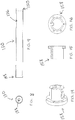
- a beat roller assembly (134) may further comprise a support plate (140) and a shaft (142).
- Support plate (140) may be a generally circular plate of suitable thickness having a central cavity (144) surrounded by one or more periphery holes (146), as shown in FIG. 12 .
- Shaft (142) having a generally cylindrical shape as shown in FIG. 13 , may be positioned through the central cavity (144) in support plate (140).
- a beat roller (130), having a first end (148) and a second end (150) may be placed end to end between two support plates (140) and secured by the placement of one or more fasteners, such as a dowel, through the one or more periphery holes (146) in the support plates (140).
- a beat roller assembly (134) may comprise a bushing (158) like that shown in FIGS. 14-16 .
- a bushing (158) may be positioned through the central cavity (144) of support plate (140) to facilitate the positioning of shaft (142).
- a bushing (158) may be positioned through each support plate (140) included in assembly (134).
- a beat roller assembly (134) may be assembled having a plurality of beat rollers (130) positioned between a plurality of support plates (140) that are secured together by a central shaft (142) that extends through the cavities (144) in the support plates (140).
- the beat roller assembly (134) may comprise any number of beat rollers (130) and support plates (140).
- the assembly (134) comprises four support plates (140) and a total of twenty-four beat rollers (130).
- the twenty-four beat rollers (130) in the assembly (134) are divided into three groups (152, 154, and 156) of eight, where eight beat rollers (130) are positioned around shaft (142) and between any two support plates (140).
- beat roller assembly (134) may comprise any number of beat rollers (130) and support plates (140).
- FIGS. 10 - 11 show an assembly (134) comprising twenty-four beat rollers (130) and four support plates (140).
- vibrating module (104) may comprise any number of beat roller assemblies (134).
- a beat roller assembly (134) may pulse and/or rotate along the conveyor (128) to dislodge or loosen the dirt on a mat.
- the optimal pulse depth of a beat roller assembly (134) may be determined by the number of beat rollers (130) included in the beat roller assembly (134).
- a pulse depth may average, for example, 0.100 inches, and the pulse depth may be adjustable depending on the mat being cleaned by the system.
- a beat roller (130) and/or a beat roller assembly (134) may contact the mat on the conveyor (128). Alternatively, the beat roller (130) and/or beat roller assembly (134) may contact the underside of the conveyor (128).
- Vibration module (104) may further comprise an apparatus to collect the dirt being shaken or loosened from the mat.
- Any suitable apparatus may be used and positioned in any suitable manner.
- a pan may be positioned underneath the conveyor (128) in alignment with the beat rollers (130). The pan may collect any dirt dislodged from the mat due to the movement of conveyor (128) and/or contact with the beat rollers (130). Even further, a dirt collector may be positioned below and along the length of the vibration module (104).
- vibration module (104) is merely one example. Any other suitable type of vibration module (104) and associated components may be used. By way of example only, vibration module (104) may also comprise a vacuum to transport the dirt away from the system (100). Alternatively, vibration module (104) may have any other suitable components, features, configurations, functionalities, operability, etc. Other suitable variations of vibration module (104) and associated components will be apparent to those of ordinary skill in the art in view of the teachings herein.
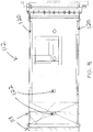
- mat cleaning system (100) further comprises a washing module (106) as shown in FIG. 17 -18 .
- washing module (106) comprises a conveyor (170), which may or may not be the same conveyor (128) from the vibration module (104).
- washing module (106) may comprise one or more devices for washing and/or rinsing the mat.
- One exemplary process for washing the mat comprises first washing the mat with a chemical-based wash using a high-volume, low-pressure spray nozzle to further clean the mat and dislodge any remaining unwanted matter.
- a chemical-based wash using a high-volume, low-pressure spray nozzle to further clean the mat and dislodge any remaining unwanted matter.
- a relatively lower amount of chemical wash may be required as compared with prior art cleaning processes.
- a low-pressure wash may be used, which reduces the amount of wear to the mat being cleaned.
- the mat preferably may also be rinsed with a high-volume, low-pressure fresh water rinse.
- Water may be reused and recycled in the washing module (106).
- the reused water may be collected in any suitable manner.
- the recycled water may be cleaned prior to its future use.
- washing module (106) may comprise a blow off, wherein excess water or chemical agent remaining after the wash and rinse may be blown off the mat with a blower.
- other agents may be used to clean and/or rinse the mat, including but not limited to detergents, anti-static agents, anti-stain agents, deodorants, perfumes, etc.
- the temperature of the washing and rinsing in module (106) may be varied.
- a vibration module (104) wherein dirt is dislodged from the mat prior to feeding it through a washing module (106)
- a lower temperature wash and/or rinse may be effective to clean the mat.
- a person of ordinary skill in the art will appreciated that either or both sides of a mat may be washed and/or rinsed in the washing module (106).
- the washing module (106) comprises an anti-flip roller bar situated at one end of conveyor (170) to prevent or restrict a mat from flipping over.
- washing module (106) is merely one example. Any other suitable type of washing module (106) and associated components may be used.
- washing module (106) may comprise a high-volume, low-pressure blow off, whereby air is blown around the mat to remove any chemical wash and/or water remaining on the mat.
- the drying module (108) may comprise this blow off stage.
- Washing module (106) may have any other suitable components, features, configurations, functionalities, operability, etc. Other suitable variations of washing module (106) and associated components will be apparent to those of ordinary skill in the art in view of the teachings herein.
- drying module (108) may further comprise a conveyor (180), a vibratory beater (182), a vacuum (184), and a dryer (186). Drying module (108) may include any one of those features either separately or in any suitable combination.
- drying module (108) may consist solely of a vibratory beater (182) and a vacuum (184).
- Conveyor (180) may be similar or identical to the conveyor (128) of the vibration module (104).
- Vibratory beater (182) may be identical to the beat roller (130) or beat roller assembly (134) described in the vibration module (104). Vibratory beater (182) may contact the mat on the conveyor (180) or it may contact the underside of the conveyor (180).
- Module (108) may vibrate at a given frequency to jostle the mat and shake off any chemical wash and/or water rinse remaining on or in the mat from the washing module (106). Any suitable vibration frequency may be used. In one embodiment, the vibration frequency is at least 60 Hz and adjustable to 120 Hz. Preferably, the frequency ranges from 70 - 100 Hz.
- a vacuum (184), through which a mat may travel, may also be used to dry off a mat after the washing module (106).
- a vacuum (184) may be, for example, a two-zone vacuum.
- vacuum (184) may comprise a nozzle block (188), a belt support (202), and a nozzle tube seal (190).
- vacuum (184) may also comprise plenum and piping (183), a wet cyclone separator (185), and a turbine fan (187).
- a nozzle block (188) may comprise a generally rectangular plate of suitable thickness with grooves (192) extending along the width of the plate.
- Nozzle block (188) may be manufactured out of any suitable material, for example, an ultra high molecular weight plastic.
- FIGS. 21 and 23 show that nozzle block (188) may comprise any number of countersunk and slotted mounting holes (194) As shown in FIG. 24 , mounting hole (194) may not have a constant width as it extends through the generally rectangular plate of nozzle block (188) from a first surface (196) to a second surface (198).
- nozzle block (188) may comprise a rounded edge (200) at the edge of the plate, as shown in FIG. 25 .
- FIG. 26 shows that a nozzle tube seal (190) of vacuum (184) may be situated between two nozzle blocks (188), with a wire belt conveyor (206) positioned in between.
- Vacuum drying may be achieved when a static vacuum pressure is balanced with the airflow in nozzle block (188).
- vacuum drying efficiency may be achieved through nozzle tube seal (190) when static vacuum pressure is a minimum of 5 inches of Hg and is balanced with a minimum of 20 CFM of airflow per inch of nozzle width.
- a belt support (202) may be located in between the two nozzle blocks (188), as shown in FIG. 26 .
- Belt support (202) may have a general T-shape as shown in FIG. 27 - 28 , with a curved cutout (204) located in a surface of the belt-support (202), to support the wire belt conveyor (206).
- the curved surface (204) of the belt support (202) may also provide a curved conveyor belt path under vacuum. This curved path may open up the pile side or underside of a mat to improve the vacuum efficiency in addition to providing support for the conveyor belt (206) under vacuum.
- the nozzle tube seal (190) is designed to allow a consistent vacuum pressure seal on any width mat by rotating and sealing above the wire conveyor belt (206) and nozzle bocks (188). This rotational sealing may allow a mat or any flat object to be vacuumed with a consistent vacuum draw on mats of any width. Further, the rotating seal may provide long service life due to rotation and negligible wear.
- the nozzle blocks (188) also may provide a mating seal surface for the nozzle tube seal (190). Nozzle blocks (188) may provide precise control of vacuum air flow and air velocity. As the mat is passing between the wire belt conveyor (206) and the nozzle tube seal (190), the vacuum air flow may remove substantial amounts of moisture.
- This moisture may be pulled through the nozzle plenum and piping (183) where it may then be separated from the airflow by a wet cyclone separator (185), as shown in FIG. 19 .
- the separated moisture may also be collected and discharged or reused and the dry air flow may continue through a turbine fan (187).
- drying module (108) may also comprise one or more other dryers (186).
- a typical dryer (186) may have a number of components, included but not limited to a turbine, a wet separator, a purge tank, and a nozzle.
- an suitable dryer or drying method may be used in the drying module (108).
- dryer (186) could comprise one or more of the following: a cool air dryer, a high-volume, low-pressure dryer, a heated low velocity dryer, and a hot air dryer.
- a mat would encounter the following dryer mechanisms in a drying module (108): a cool air blow dryer, a vibrating beater, a vacuum dryer, a hot air dryer, and a cool down blower.
- a hot air dryer (208) An example of a hot air dryer (208) is shown in FIG. 29 .
- Hot air dryer (208) may comprise a number of components including but not limited to a gas train (210), a thermocouple (212), and a sliding damper (214).
- Hot air dryer (208) may run at any suitable power, but preferably is run at 1 MMBTU.
- a dryer (186) and/or (208) may be operated at any suitable temperature. For example, dryer (186) may be operated up to 427 degrees F.
- drying module (108) may be used in any suitable order as will be appreciated by one of ordinary skill in the art.
- a mat entering the drying module (108) may encounter a vibratory beater (182) before proceeding along the conveyor (180).
- drying module (108) may comprise a wrinkle remover spreader roll, which may be engaged with a mat prior to a vacuum dry, to flatten the mat to improve drying efficiency.
- the components and methods of the drying module (108) may be practiced separately or in conjunction with one or more other components, methods, or modules.
- the above-described drying module (108) is merely one example. Any other suitable type of drying module (108) and associated components may be used. Drying module (108) may have any other suitable components, features, configurations, functionalities, operability, etc. Other suitable variations of drying module (108) and associated components will be apparent to those of ordinary skill in the art in view of the teachings herein.
- a fifth module that the mat cleaning system (100) may comprise is the discharge module (110).
- the mat may be fed onto a table (220) in the discharge module (110).
- Table (220) may be vibratory and used to hover the mat over the table (220) for transport and/or alignment of the mat.
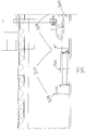
- FIGS. 31 - 31(a) shows a dual action conveyor (222) upon which a mat may be fed in the discharge module (110).
- the dual action conveyor (222) may be driven with free spinning rollers (223) or vibratory rollers.
- the dual action aspect of either the free spinning rollers or the vibratory rollers may allow a mat to be discharged from a dryer (186) at a dryer conveyor speed and then transferred to an discharge module (110) at a different speed.
- Discharge module (110) may also include an auto-roll discharge.
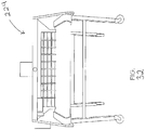
- the auto-roll discharge may be performed by an auto-roll discharge apparatus (224), as shown in FIG. 32 .
- Such a discharge apparatus (224) may sort and roll the mats as they go through the discharge module (110).
- Such an automatic rolling system may reduce the number of people needed to operate the system (100).
- the discharge apparatus (224) may also sort according to any suitable factor as will be appreciated by one or ordinary skill in the art. For example, apparatus (224) may sort the mats according to size, weight, material type, or some other factor. After discharge, the mats may be placed in a mat cart (226). Alternatively, system (100) may include a manual sort.
- Such a dual action conveyor (222) or a vibrating table (220) may permit a quality control inspection and a manual sort.
- any suitable quality control inspection may be used during the discharge module (110).
- the quality control inspection may include a review of the mat for tears, stains, worn spots, or any other quality-related issues.
- the inspection may include inspecting both sides of the entire mat. Alternatively, the inspection may only include inspecting either the pile side or the underside of the mat.
- a quality control inspection may also include the treatment of stains or spots on the mat and/or the removal of damaged mats from the system (100).
- discharge module (110) is merely one example. Any other suitable type of discharge module (110) and associated components may be used. By way of example only, discharge module (110) may not comprise an auto-roll discharge. As will other module components described herein, discharge apparatus (224) is merely optional, and may be modified, substituted, supplemented, or omitted as desired. Discharge module (110) may have any other suitable components, features, configurations, functionalities, operability, etc. Other suitable variations of washing module (106) and associated components will be apparent to those of ordinary skill in the art in view of the teachings herein.
- system (100) is merely one example of a mat cleaning system. Any other suitable type of modules and associated components may be used. By way of example only, the above-mentioned modules may be modified, substituted, supplemented, re-ordered or omitted as desired.
- system (100) may include additional safety features such as safety interlocks, guards, and/or e-stops on all moving parts.
- System (100) may have any other suitable components, features, configurations, functionalities, operability, etc. Other suitable variations of system (100) and associated components will be apparent to those of ordinary skill in the art in view of the teachings herein.
- the figures depict modules wherein the movement of the mat through the module was from left to right in a given figure.
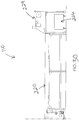
- the conveyor travel in FIG. 30 is generally from left to right. Such a direction is in no way intended and should not be used to limit the practicing of the invention.
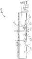
- FIGS. 33 - 35 depict a particular embodiment of a mat cleaning system (300).
- a system also comprises a loading module (302), a vibration module (304), a washing module (306), a drying module (308), and a discharge module (310).
- the washing module (306) may comprise a number of different types of washes.
- washing module (306) may include a high-volume, low-pressure wash (312), a high-volume, low-pressure rinse (314), a free rinse (316), and a high-volume, low-pressure blow dry, wherein air is blown around the mat to remove excess water or chemical wash remaining on a mat.
- the wash of the mat may be conducted with a chemical-based agent, whereas the rinses of the mat may be conducted with water.
- Drying module (308) may also comprise a number of sub-components including but not limited to a vibratory dryer (320), which comprises a vibratory beater that jostles the mat to dislodge an remaining water or chemical wash.
- a vacuum dryer (322) and a gas hot air dryer (324) may be included as part of the drying module (308).
- the discharge module (310) may comprise a dual action conveyor (326) and a discharge apparatus (328) for automatically rolling up the mats as they leave the system (300).
- the conveyor travel in FIG. 34 is generally from right to left. Such a direction is in no way intended and should not be used to limit the practicing of the invention.
- system (300) is merely one example of a mat cleaning system. Any other suitable type of modules and associated components may be used. By way of example only, the above-mentioned modules may be modified, substituted, supplemented, re-ordered or omitted as desired.
- System (300) may have any other suitable components, features, configurations, functionalities, operability, etc. Other suitable variations of system (300) and associated components will be apparent to those of ordinary skill in the art in view of the teachings herein.
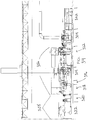
- FIG. 36 depicts another particular embodiment of a system (400) for cleansing mats.
- the system (400) comprises loading module (402), a vibration module (404), a washing module (406), a drying module (408), and a discharge module (410).
- a mat may be first loaded onto a gravity roller table (412), which employs gravity to feed the mat into the system (400), in the loading module (402). The mat is loaded pile side down.
- a quality control inspection may be performed on the mat prior to its traveling by conveyor (414) to the next module.
- the mat moves to the vibration module (404), comprising two vibratory rollers (416), after leaving the loading module.
- Each vibratory roller (416) jostles or otherwise rattles the mat to cause dirt to become dislodged from the mat.
- This dirt falls into the dirt pan (418) positioned below the vibratory module (404).
- a blower and a vacuum may be situated beneath vibratory module (404) to gather and dispose of the unwanted dirt.
- washing module (406) comprises two rinse cycles (420), followed by a first wash (422) and a second wash (424), followed by two rinse cycles (426).
- the mat may be washed using recycled water. Only during the first washing (422) is any type of chemical wash used. No chemical wash is used during the second washing (424). After the washing is complete, the mat is rinsed twice again (426). During the rinses (420, 426) multiple high volume, low pressure air nozzles may spray the mat to blow dirt from it.
- Drying module (408) may comprise a blow dryer (428) and a dry vacuum (430).
- the mat may first be exposed to two blow dryers (428). After drying the mat using blow dryers (428), the dry vacuum (430) may be applied to the mat. After leaving the drying module (408), the mat may travels on the conveyor (414) to be sorted or otherwise handled as applicable during the discharge module (410).
- system (400) is merely one example of a mat cleaning system. Any other suitable type of modules and associated components may be used. By way of example only, the above-mentioned modules may be modified, substituted, supplemented, re-ordered or omitted as desired.
- System (400) may have any other suitable components, features, configurations, functionalities, operability, etc. Other suitable variations of system (400) and associated components will be apparent to those of ordinary skill in the art in view of the teachings herein.
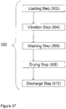
- FIG. 37 displays a method (500) of cleaning mats.
- Method (500) comprises a number of steps, each of which may be practiced separately or in combination with any of the other steps.
- one method (500) of cleaning mats comprises a loading step (502), a vibration step (504), a washing step (506), a drying step (508), and a discharge step (510).
- a user may feed a mat into the system and onto a table, which may be, for example, an air-float table or a gravity roller table.
- a user may feed the mat onto a conveyor.
- the mat may be rotated or straightened out by a user or by load rollers or edge guides or the like.
- a user may also perform a quality control inspection of the mat prior to, during, or subsequent to feeding the mat onto the table or conveyor.
- Any suitable quality control inspection may be used.
- the quality control inspection may include a review of the mat for tears, stains, or any other quality-related issues.
- the inspection may include inspecting both sides of the entire mat.
- the inspection may only include inspecting either the pile side or the underside of the mat.
- the inspection of the pile side of the mat may occur prior to flipping the mat pile side down and feeding the mat onto the table or conveyor. Inspection of the underside portion of the mat may occur after loading the mat onto the table or conveyor pile side down.
- a quality control inspection may also include the pretreatment of stains or spots on the mat and/or the removal of damaged mats from the system.
- the mat After being fed through the loading step (502), the mat may be fed through the vibration step (504).
- a mat may be transported from an air-float table or gravity roller table and positioned onto a conveyor. There, the mat may be shaken or jostled due to the movement of the conveyor. This may cause dirt to be loosened or dislodged from the mat.
- the mat may also be fed through contact with at least one beat roller assembly. Contact with the beat roller assembly may also cause any dirt located on or in the mat to be loosened or dislodged. The loosened and/or dislodged dirt may be collected.
- a dirt collector pan may be placed underneath the conveyor to collect the dirt that falls from the mat during the vibratory step (504).
- a vacuum or equivalent device may also be placed near the conveyor to collect the dirt from the mat.
- the mat may be fed through the washing step (506). There, the mat may continue along on a conveyor.
- the washing step (504) the mat may undergo one or more washes and/or rinses.
- the mat may first be washed with a chemical-based agent using a high volume, low pressure nozzle.
- the mat may be rinsed one or more times with water.
- the water may be reused and recycled in the washing step (506).
- the reused water may be collected in any suitable manner.
- the recycled water may be cleaned prior to its future use.
- the mat may be rinsed one or more times before it is washed.
- washing step (506) may include blowing air or another gas over and around the mat to remove an water or chemical agent remaining on the mat.
- the mat may be fed through the drying step (508).
- This step may comprise a number of sub-steps, including but not limited to vibrating the mat with a conveyor and/or a beater, passing the mat through a vacuum, and passing the mat through one or more dryers.
- the vacuum may be separate from the dryer or may be part of a dryer, for example a vacuum dryer.
- Other dryers that may be employed during the drying step (508) include but should not be limited to: a cool air dryer, a high-volume, low-pressure dryer, a heated low velocity dryer, and a hot air dryer.
- a mat may be fed through the sub-steps of the drying step (508) in any suitable order as will be apparent to one of ordinary skill in the art. For example, the mat may be fed through a dryer first and then fed through a vacuum.
- the discharge step (510) comprises sub-steps related to discharging, rolling, and sorting mats from the system.
- the discharge step (510) may include rolling the mats as they exit the conveyor or table.
- Discharge step (510) may also comprise a sorting step, whereby the mat is either manually or automatically sorted according to any suitable factor, such as size, weight, material type, etc.
- the discharge step (510) may comprise a quality control inspection.
- the quality control inspection may include a review of the mat for tears, stains, or any other quality-related issues.
- the inspection may include inspecting both sides of the entire mat.
- the inspection may only include inspecting either the pile side or the underside of the mat.
- a quality control inspection may also include the treatment of stains or spots on the mat and/or the removal of damaged mats from the system.
- the above-described method (500) is merely one example of a mat cleaning process.
- the process (500) may comprise any other suitable steps and modules and associated components.
Landscapes
- Engineering & Computer Science (AREA)
- Textile Engineering (AREA)
- Mechanical Engineering (AREA)
- Cleaning In General (AREA)
- Cleaning By Liquid Or Steam (AREA)
Claims (21)
- Procédé de nettoyage d'un objet plat comprenant l'étape de fourniture d'un objet plat et l'application à l'objet plat des étapes suivantes :(a) le chargement dudit objet plat sur un transporteur (170) par un module de chargement (102, 302, 402) ;(b) la mise en contact de l'objet plat avec au moins un rouleau de battage (130) d'un module vibreur (104, 304, 404) afin de déloger de la matière de l'objet plat ;(c) le lavage et le rinçage de l'objet plat par un module de lavage (106, 306, 406)(d) le séchage de l'objet plat par un module de séchage (108, 308, 408) ; et(e) un module de déchargement (110, 310, 410) pour décharger l'objet plat, caractérisé en ce quel'objet plat est transporté sur un transporteur (170) à travers le module de lavage (106, 306, 406) et son retournement est empêché ou restreint par une barre roulante anti-retournement située à une extrémité du transporteur (170).
- Procédé selon la revendication 1, dans lequel l'objet plat est un tapis.
- Procédé selon la revendication 2, comprenant en outre l'étape d'inspection de l'objet plat à la recherche d'une usure ou d'un endommagement.
- Procédé selon la revendication 2, comprenant en outre l'étape d'orientation de l'objet plat pour le mettre en contact avec au moins un rouleau de battage (130) dans le module vibreur.
- Procédé selon la revendication 2, dans lequel l'étape de séchage comprend en outre l'utilisation d'au moins un vide (184).
- Procédé selon la revendication 2, comprenant en outre l'étape d'enroulement de l'objet plat.
- Procédé selon la revendication 2, comprenant en outre l'étape de tri de l'objet plat en fonction de critères sélectionnés dans le groupe consistant en :(a) taille ;(b) poids ; et(c) type de matériau.
- Système de nettoyage d'objet plat, comprenant :(a) un module de chargement (102, 302, 402) pour avancer l'objet plat sur un transporteur ;(b) un module vibreur (104, 304, 404) pour mettre en contact l'objet plat avec au moins un rouleau de battage (130) afin de déloger de la matière de l'objet plat ;(c) un module de lavage (106, 306, 406) pour laver et rincer l'objet plat ;(d) un module de séchage (108, 308, 408) pour sécher l'objet plat ; et(e) un module de déchargement (110, 310, 410) pour décharger l'objet plat du système,caractérisé en ce que
le module de lavage (106, 306, 406) comporte un transporteur (170) pour l'objet plat et une barre roulante anti-retournement située à une extrémité du transporteur (170) pour empêcher ou restreindre le retournement de l'objet plat. - Système de nettoyage selon la revendication 8, dans lequel l'objet plat fait partie du système de nettoyage et l'objet plat est un tapis.
- Système de nettoyage selon la revendication 9 dans lequel(a) le module de chargement (102, 302, 402) comprend en outre une table (112, 412) sur laquelle peut reposer le tapis ;(b) le module vibreur (104, 304, 404) comprend en outre un transporteur (128) et au moins un rouleau de battage (130), le transporteur (128) partant de la table (112) du module de chargement ;(c) le module de lavage (106, 306, 406) comprend en outre un transporteur (170), au moins un instrument de lavage, et au moins un instrument de rinçage, le transporteur (170) partant du transporteur (128) du module vibreur ;(d) le module de séchage (108, 308, 408) comprend en outre un transporteur (180), au moins un batteur vibrant (182), et au moins un séchoir (186), le transporteur (180) du module de séchage partant du transporteur (170) du module de lavage ; et(e) le module de décharge (110, 310, 410) comprend en outre un transporteur à double action (222, 326) et un appareil de décharge (224, 328), le transporteur à double action (222) partant du transporteur (180) du module de séchage.
- Système de nettoyage selon la revendication 10, dans lequel la table du module de chargement (102) est une table à feuille aéroportée (112) comportant une pluralité d'orifices (122) traversant celle-ci, à travers lesquels de l'air peut être soufflé pour une avancée ergonomique du tapis.
- Système de nettoyage selon la revendication 11, comprenant en outre un bac de collecte (124) situé en dessous de la table à feuille aéroportée (112) pour collecter les saletés.
- Système de nettoyage selon la revendication 10, dans lequel la table du module de chargement (402) est une table à rouleaux libres (412).
- Système de nettoyage selon la revendication 10, dans lequel la table du module de chargement (102, 302, 402) comprend en outre au moins un rouleau de chargement qui peut être tourné pour redresser l'objet plat qui est disposé sur la table.
- Système de nettoyage selon la revendication 10, dans lequel le module de lavage (106, 306, 406) comprend en outre une buse à haut débit, basse pression, à travers laquelle sont pulvérisées la solution de lavage et la solution de rinçage.
- Système de nettoyage selon la revendication 10, dans lequel l'appareil de déchargement (224, 328) du module de déchargement (110, 310, 410) enroule l'objet plat à sa sortie du système.
- Système de nettoyage selon la revendication 14, dans lequel l'appareil de déchargement trie l'objet plat à sa sortie du système.
- Système de nettoyage selon la revendication 8 dans lequel le module vibreur (104, 304, 404) comprend en outre :(a) un transporteur (128) sur lequel peut reposer l'objet plat ; et(b) au moins un rouleau de battage (130), l'au moins un rouleau de battage (130) comprenant un arbre sensiblement cylindrique (136) qui définit un alésage central (138) ; dans lequel la rotation de l'au moins un rouleau de battage (130) l'amène en contact avec l'objet plat.
- Système de nettoyage selon la revendication 18, dans lequel l'au moins un rouleau de battage (130) fait partie d'un ensemble de rouleaux de battage (134), l'ensemble de rouleaux de battage comprenant :(a) un arbre généralement cylindrique (142) ;(b) une plaque de support (140) présentant une cavité centrale (144) et une pluralité d'orifices périphériques (146), l'arbre généralement cylindrique (142) étant positionné à travers la cavité centrale (144) ; et(c) au moins un rouleau de battage (130) présentant une première extrémité et une seconde extrémité ainsi qu'une paire de paliers scellés à grande vitesse (160), l'une ou l'autre de la première extrémité ou de la seconde extrémité étant fixée à la plaque de support (144) à travers un orifice de la pluralité d'orifices périphériques (146).
- Système de nettoyage selon la revendication 18 comprenant en outre un collecteur de saletés positionné pour collecter les saletés tombant du transporteur (128).
- Système de nettoyage selon la revendication 8 dans lequel le module de séchage (108, 308, 408) comprend en outre :(a) un transporteur (180) sur lequel peut reposer l'objet plat, le transporteur (180) pouvant vibrer à une certaine fréquence ;(b) au moins un batteur vibrant (182), l'au moins un batteur vibrant (182) comprenant un arbre sensiblement cylindrique qui définit un alésage central, la rotation de l'au moins un batteur vibrant (182) l'amenant en contact avec le transporteur (180) ; et(c) un séchoir (186) dans lequel sont placés le transporteur (180) et l'au moins un batteur vibrant (182) le séchoir (186) étant sélectionné dans le groupe consistant en : un séchoir à air froid ; un séchoir à vide (322); un séchoir à air chaud de grand volume (208, 324); une soufflante de refroidissement ; et des combinaisons de ceux-ci.
Applications Claiming Priority (3)
| Application Number | Priority Date | Filing Date | Title |
|---|---|---|---|
| US5995208P | 2008-06-18 | 2008-06-18 | |
| US12/487,396 US20100051058A1 (en) | 2008-06-18 | 2009-06-18 | Automated Mat Cleaning and Handling System and Method |
| PCT/US2009/047812 WO2009155429A1 (fr) | 2008-06-18 | 2009-06-18 | Système et procédé automatisés de nettoyage et manipulation de tapis |
Publications (3)
| Publication Number | Publication Date |
|---|---|
| EP2303086A1 EP2303086A1 (fr) | 2011-04-06 |
| EP2303086A4 EP2303086A4 (fr) | 2014-10-29 |
| EP2303086B1 true EP2303086B1 (fr) | 2021-07-28 |
Family
ID=41434444
Family Applications (1)
| Application Number | Title | Priority Date | Filing Date |
|---|---|---|---|
| EP09767738.9A Active EP2303086B1 (fr) | 2008-06-18 | 2009-06-18 | Système et procédé automatisés de nettoyage et manipulation de tapis |
Country Status (6)
| Country | Link |
|---|---|
| US (1) | US20100051058A1 (fr) |
| EP (1) | EP2303086B1 (fr) |
| CN (1) | CN102065739B (fr) |
| CA (1) | CA2727190C (fr) |
| MX (1) | MX348554B (fr) |
| WO (1) | WO2009155429A1 (fr) |
Families Citing this family (11)
| Publication number | Priority date | Publication date | Assignee | Title |
|---|---|---|---|---|
| US7716849B1 (en) * | 2006-07-12 | 2010-05-18 | Neil Hicks | Glove dryer |
| US10350648B2 (en) | 2015-08-06 | 2019-07-16 | 0959690 B.C. Ltd. | Mat cleaning and drying apparatus and method |
| DE102017001586A1 (de) * | 2016-11-11 | 2018-05-17 | Herbert Kannegiesser Gmbh | Verfahren und Vorrichtung zur Behandlung von Wäsche |
| CN108277600B (zh) * | 2018-02-12 | 2020-06-09 | 泉州台商投资区国进信息技术有限公司 | 一种一体式纺织布料清洗烘干设备及其工作流程 |
| CN108998904A (zh) * | 2018-07-27 | 2018-12-14 | 陈璐 | 一种纺织品生产用清洗装置 |
| US12269069B2 (en) | 2019-10-25 | 2025-04-08 | Northern Mat & Bridge (Gp) Ltd. | Mat washing system |
| TWM599894U (zh) * | 2020-05-14 | 2020-08-11 | 佳格食品股份有限公司 | 噴料滾筒系統 |
| CN112440007A (zh) * | 2020-11-04 | 2021-03-05 | 宁波经纬数控设备有限公司 | 模块化切割设备 |
| CN112281287B (zh) * | 2020-11-04 | 2022-08-26 | 财金知产信息科技(山东)有限公司 | 一种用于纺织机纺织尘吸收处理的设备 |
| CN114457575A (zh) * | 2022-02-14 | 2022-05-10 | 深圳市富阳鑫纺织品有限公司 | 一种棉质抗菌面料的浮毛去除装置 |
| CN116999241B (zh) * | 2023-07-24 | 2024-10-22 | 安吉县慧峰医用敷料有限责任公司 | 一种医用绷带生产加工工艺 |
Citations (1)
| Publication number | Priority date | Publication date | Assignee | Title |
|---|---|---|---|---|
| US4301577A (en) * | 1979-08-30 | 1981-11-24 | Bigelow-Sanford, Inc. | Process for treating tufted pile fabric |
Family Cites Families (16)
| Publication number | Priority date | Publication date | Assignee | Title |
|---|---|---|---|---|
| US1769522A (en) * | 1925-12-30 | 1930-07-01 | North H Losey | Vacuum-sweeper construction |
| US1883851A (en) * | 1928-07-02 | 1932-10-18 | Mae F Grover | Beater for cleaning rugs |
| US1925377A (en) * | 1930-07-14 | 1933-09-05 | C W Smith | Rug and carpet cleaning machine |
| US3424324A (en) * | 1966-02-25 | 1969-01-28 | Fmc Corp | Method of selecting a plurality of articles in a warehouse |
| US3592329A (en) * | 1966-10-27 | 1971-07-13 | Gen Logistics | Differential pressure conveyors |
| US3518710A (en) * | 1968-07-24 | 1970-07-07 | Mattron Inc | Rug cleaning machine |
| US3574526A (en) * | 1969-04-07 | 1971-04-13 | Jeffrey K Bell | Rug cleaning apparatus and method |
| US3747155A (en) * | 1971-07-09 | 1973-07-24 | G Koellisch | Nozzle construction for portable carpet cleaning machine |
| FR2233808A5 (en) * | 1973-06-18 | 1975-01-10 | Chazalon Jacques | Carpet cleaning machine - cleaning fluid applied and carpet passed between brush rollers, rinsed and squeezed dry |
| US4103389A (en) * | 1976-03-25 | 1978-08-01 | Textile Associates, Inc. | Cleaning unit |
| US4104755A (en) * | 1976-08-02 | 1978-08-08 | Smith Judson L | Vehicle floor mat washer |
| US4226641A (en) * | 1978-02-21 | 1980-10-07 | Bode Sr Howard E | Mat or rug cleaning process using roller brush |
| US4268929A (en) * | 1980-02-04 | 1981-05-26 | Clean-Tex A/S | Method and apparatus for cleaning rugs and mats |
| US4453386A (en) * | 1982-05-21 | 1984-06-12 | Wilkins Ronald W | High capacity mat cleaning machine |
| KR100369200B1 (ko) * | 1994-04-30 | 2003-03-26 | 가부시키가이샤 세이부 기켄 | 고속유체에의한저온급속탈수건조의방법 |
| WO2003106760A1 (fr) * | 2002-06-13 | 2003-12-24 | Milliken Industrials Limited | Tapis |
-
2009
- 2009-06-18 CA CA2727190A patent/CA2727190C/fr active Active
- 2009-06-18 CN CN200980122758.XA patent/CN102065739B/zh active Active
- 2009-06-18 MX MX2010013907A patent/MX348554B/es active IP Right Grant
- 2009-06-18 US US12/487,396 patent/US20100051058A1/en not_active Abandoned
- 2009-06-18 EP EP09767738.9A patent/EP2303086B1/fr active Active
- 2009-06-18 WO PCT/US2009/047812 patent/WO2009155429A1/fr not_active Ceased
Patent Citations (1)
| Publication number | Priority date | Publication date | Assignee | Title |
|---|---|---|---|---|
| US4301577A (en) * | 1979-08-30 | 1981-11-24 | Bigelow-Sanford, Inc. | Process for treating tufted pile fabric |
Also Published As
| Publication number | Publication date |
|---|---|
| CA2727190A1 (fr) | 2009-12-23 |
| WO2009155429A1 (fr) | 2009-12-23 |
| CN102065739B (zh) | 2015-08-12 |
| EP2303086A1 (fr) | 2011-04-06 |
| CN102065739A (zh) | 2011-05-18 |
| MX2010013907A (es) | 2011-05-19 |
| EP2303086A4 (fr) | 2014-10-29 |
| US20100051058A1 (en) | 2010-03-04 |
| CA2727190C (fr) | 2016-07-26 |
| MX348554B (es) | 2017-06-16 |
Similar Documents
| Publication | Publication Date | Title |
|---|---|---|
| EP2303086B1 (fr) | Système et procédé automatisés de nettoyage et manipulation de tapis | |
| JP5416007B2 (ja) | フィルタ洗浄乾燥システム及びフィルタ洗浄乾燥方法 | |
| US20110100396A1 (en) | Equipment and method for washing a carpet | |
| US10350648B2 (en) | Mat cleaning and drying apparatus and method | |
| US20130014783A1 (en) | Method for cleaning surfaces, in particular glass panes | |
| KR20090013468A (ko) | 초음파세척 및 건조가 이루어지는 산업용 세척기 | |
| US20220184246A1 (en) | System for cleaning modular belts | |
| KR102211428B1 (ko) | 벨트 컨베이어의 벨트 크리닝 장치 | |
| US4103389A (en) | Cleaning unit | |
| US3805316A (en) | Tray drying apparatus | |
| JP2003301368A (ja) | 検反機 | |
| JP2001046990A (ja) | マット洗浄機 | |
| KR20120118984A (ko) | 필터 청소장치 | |
| KR100877051B1 (ko) | 세척 및 건조가 이루어지는 산업용 세척기 및 그를 이용한세척방법 | |
| JP2002113291A (ja) | 乾燥装置 | |
| JP2009119737A (ja) | 農業用マルチシートの処理装置 | |
| KR100893489B1 (ko) | 디스케일러용 쇼트볼 선별 장치 | |
| JPS6143585Y2 (fr) | ||
| CN221768365U (zh) | 一种集成电路板蚀刻装置 | |
| JPH10309542A (ja) | 球根類洗浄機 | |
| CN223455026U (zh) | 一种具有成品预处理功能的卧式搓丝机 | |
| CN222095653U (zh) | 一种可转动式阀门打磨装置 | |
| JP2001187367A (ja) | 手袋の洗浄装置及び洗浄方法 | |
| CN220423049U (zh) | 一种酱料原料清洗装置 | |
| CN220269742U (zh) | 一种冷却装置 |
Legal Events
| Date | Code | Title | Description |
|---|---|---|---|
| PUAI | Public reference made under article 153(3) epc to a published international application that has entered the european phase |
Free format text: ORIGINAL CODE: 0009012 |
|
| 17P | Request for examination filed |
Effective date: 20110113 |
|
| AK | Designated contracting states |
Kind code of ref document: A1 Designated state(s): AT BE BG CH CY CZ DE DK EE ES FI FR GB GR HR HU IE IS IT LI LT LU LV MC MK MT NL NO PL PT RO SE SI SK TR |
|
| AX | Request for extension of the european patent |
Extension state: AL BA RS |
|
| DAX | Request for extension of the european patent (deleted) | ||
| A4 | Supplementary search report drawn up and despatched |
Effective date: 20140926 |
|
| RIC1 | Information provided on ipc code assigned before grant |
Ipc: A47L 13/00 20060101AFI20140922BHEP |
|
| STAA | Information on the status of an ep patent application or granted ep patent |
Free format text: STATUS: EXAMINATION IS IN PROGRESS |
|
| 17Q | First examination report despatched |
Effective date: 20180102 |
|
| RAP1 | Party data changed (applicant data changed or rights of an application transferred) |
Owner name: CINTAS CORPORATE SERVICES, INC. |
|
| REG | Reference to a national code |
Ref country code: DE Ref legal event code: R079 Ref document number: 602009063914 Country of ref document: DE Free format text: PREVIOUS MAIN CLASS: A47L0013000000 Ipc: D06G0001000000 |
|
| GRAP | Despatch of communication of intention to grant a patent |
Free format text: ORIGINAL CODE: EPIDOSNIGR1 |
|
| STAA | Information on the status of an ep patent application or granted ep patent |
Free format text: STATUS: GRANT OF PATENT IS INTENDED |
|
| RIC1 | Information provided on ipc code assigned before grant |
Ipc: D06F 31/00 20060101ALI20210125BHEP Ipc: D06G 1/00 20060101AFI20210125BHEP |
|
| INTG | Intention to grant announced |
Effective date: 20210222 |
|
| GRAS | Grant fee paid |
Free format text: ORIGINAL CODE: EPIDOSNIGR3 |
|
| GRAA | (expected) grant |
Free format text: ORIGINAL CODE: 0009210 |
|
| STAA | Information on the status of an ep patent application or granted ep patent |
Free format text: STATUS: THE PATENT HAS BEEN GRANTED |
|
| AK | Designated contracting states |
Kind code of ref document: B1 Designated state(s): AT BE BG CH CY CZ DE DK EE ES FI FR GB GR HR HU IE IS IT LI LT LU LV MC MK MT NL NO PL PT RO SE SI SK TR |
|
| REG | Reference to a national code |
Ref country code: GB Ref legal event code: FG4D |
|
| REG | Reference to a national code |
Ref country code: CH Ref legal event code: EP |
|
| REG | Reference to a national code |
Ref country code: AT Ref legal event code: REF Ref document number: 1414834 Country of ref document: AT Kind code of ref document: T Effective date: 20210815 |
|
| REG | Reference to a national code |
Ref country code: IE Ref legal event code: FG4D |
|
| REG | Reference to a national code |
Ref country code: DE Ref legal event code: R096 Ref document number: 602009063914 Country of ref document: DE |
|
| REG | Reference to a national code |
Ref country code: LT Ref legal event code: MG9D |
|
| REG | Reference to a national code |
Ref country code: NL Ref legal event code: MP Effective date: 20210728 |
|
| REG | Reference to a national code |
Ref country code: AT Ref legal event code: MK05 Ref document number: 1414834 Country of ref document: AT Kind code of ref document: T Effective date: 20210728 |
|
| PG25 | Lapsed in a contracting state [announced via postgrant information from national office to epo] |
Ref country code: SE Free format text: LAPSE BECAUSE OF FAILURE TO SUBMIT A TRANSLATION OF THE DESCRIPTION OR TO PAY THE FEE WITHIN THE PRESCRIBED TIME-LIMIT Effective date: 20210728 Ref country code: HR Free format text: LAPSE BECAUSE OF FAILURE TO SUBMIT A TRANSLATION OF THE DESCRIPTION OR TO PAY THE FEE WITHIN THE PRESCRIBED TIME-LIMIT Effective date: 20210728 Ref country code: BG Free format text: LAPSE BECAUSE OF FAILURE TO SUBMIT A TRANSLATION OF THE DESCRIPTION OR TO PAY THE FEE WITHIN THE PRESCRIBED TIME-LIMIT Effective date: 20211028 Ref country code: AT Free format text: LAPSE BECAUSE OF FAILURE TO SUBMIT A TRANSLATION OF THE DESCRIPTION OR TO PAY THE FEE WITHIN THE PRESCRIBED TIME-LIMIT Effective date: 20210728 Ref country code: LT Free format text: LAPSE BECAUSE OF FAILURE TO SUBMIT A TRANSLATION OF THE DESCRIPTION OR TO PAY THE FEE WITHIN THE PRESCRIBED TIME-LIMIT Effective date: 20210728 Ref country code: ES Free format text: LAPSE BECAUSE OF FAILURE TO SUBMIT A TRANSLATION OF THE DESCRIPTION OR TO PAY THE FEE WITHIN THE PRESCRIBED TIME-LIMIT Effective date: 20210728 Ref country code: FI Free format text: LAPSE BECAUSE OF FAILURE TO SUBMIT A TRANSLATION OF THE DESCRIPTION OR TO PAY THE FEE WITHIN THE PRESCRIBED TIME-LIMIT Effective date: 20210728 Ref country code: NO Free format text: LAPSE BECAUSE OF FAILURE TO SUBMIT A TRANSLATION OF THE DESCRIPTION OR TO PAY THE FEE WITHIN THE PRESCRIBED TIME-LIMIT Effective date: 20211028 Ref country code: NL Free format text: LAPSE BECAUSE OF FAILURE TO SUBMIT A TRANSLATION OF THE DESCRIPTION OR TO PAY THE FEE WITHIN THE PRESCRIBED TIME-LIMIT Effective date: 20210728 Ref country code: PT Free format text: LAPSE BECAUSE OF FAILURE TO SUBMIT A TRANSLATION OF THE DESCRIPTION OR TO PAY THE FEE WITHIN THE PRESCRIBED TIME-LIMIT Effective date: 20211129 |
|
| PG25 | Lapsed in a contracting state [announced via postgrant information from national office to epo] |
Ref country code: PL Free format text: LAPSE BECAUSE OF FAILURE TO SUBMIT A TRANSLATION OF THE DESCRIPTION OR TO PAY THE FEE WITHIN THE PRESCRIBED TIME-LIMIT Effective date: 20210728 Ref country code: LV Free format text: LAPSE BECAUSE OF FAILURE TO SUBMIT A TRANSLATION OF THE DESCRIPTION OR TO PAY THE FEE WITHIN THE PRESCRIBED TIME-LIMIT Effective date: 20210728 Ref country code: GR Free format text: LAPSE BECAUSE OF FAILURE TO SUBMIT A TRANSLATION OF THE DESCRIPTION OR TO PAY THE FEE WITHIN THE PRESCRIBED TIME-LIMIT Effective date: 20211029 |
|
| PG25 | Lapsed in a contracting state [announced via postgrant information from national office to epo] |
Ref country code: DK Free format text: LAPSE BECAUSE OF FAILURE TO SUBMIT A TRANSLATION OF THE DESCRIPTION OR TO PAY THE FEE WITHIN THE PRESCRIBED TIME-LIMIT Effective date: 20210728 |
|
| REG | Reference to a national code |
Ref country code: DE Ref legal event code: R097 Ref document number: 602009063914 Country of ref document: DE |
|
| PG25 | Lapsed in a contracting state [announced via postgrant information from national office to epo] |
Ref country code: SK Free format text: LAPSE BECAUSE OF FAILURE TO SUBMIT A TRANSLATION OF THE DESCRIPTION OR TO PAY THE FEE WITHIN THE PRESCRIBED TIME-LIMIT Effective date: 20210728 Ref country code: RO Free format text: LAPSE BECAUSE OF FAILURE TO SUBMIT A TRANSLATION OF THE DESCRIPTION OR TO PAY THE FEE WITHIN THE PRESCRIBED TIME-LIMIT Effective date: 20210728 Ref country code: EE Free format text: LAPSE BECAUSE OF FAILURE TO SUBMIT A TRANSLATION OF THE DESCRIPTION OR TO PAY THE FEE WITHIN THE PRESCRIBED TIME-LIMIT Effective date: 20210728 Ref country code: CZ Free format text: LAPSE BECAUSE OF FAILURE TO SUBMIT A TRANSLATION OF THE DESCRIPTION OR TO PAY THE FEE WITHIN THE PRESCRIBED TIME-LIMIT Effective date: 20210728 |
|
| PLBE | No opposition filed within time limit |
Free format text: ORIGINAL CODE: 0009261 |
|
| STAA | Information on the status of an ep patent application or granted ep patent |
Free format text: STATUS: NO OPPOSITION FILED WITHIN TIME LIMIT |
|
| 26N | No opposition filed |
Effective date: 20220429 |
|
| PG25 | Lapsed in a contracting state [announced via postgrant information from national office to epo] |
Ref country code: IT Free format text: LAPSE BECAUSE OF FAILURE TO SUBMIT A TRANSLATION OF THE DESCRIPTION OR TO PAY THE FEE WITHIN THE PRESCRIBED TIME-LIMIT Effective date: 20210728 |
|
| REG | Reference to a national code |
Ref country code: DE Ref legal event code: R119 Ref document number: 602009063914 Country of ref document: DE |
|
| PG25 | Lapsed in a contracting state [announced via postgrant information from national office to epo] |
Ref country code: MC Free format text: LAPSE BECAUSE OF FAILURE TO SUBMIT A TRANSLATION OF THE DESCRIPTION OR TO PAY THE FEE WITHIN THE PRESCRIBED TIME-LIMIT Effective date: 20210728 |
|
| REG | Reference to a national code |
Ref country code: CH Ref legal event code: PL |
|
| REG | Reference to a national code |
Ref country code: BE Ref legal event code: MM Effective date: 20220630 |
|
| GBPC | Gb: european patent ceased through non-payment of renewal fee |
Effective date: 20220618 |
|
| PG25 | Lapsed in a contracting state [announced via postgrant information from national office to epo] |
Ref country code: LU Free format text: LAPSE BECAUSE OF NON-PAYMENT OF DUE FEES Effective date: 20220618 Ref country code: LI Free format text: LAPSE BECAUSE OF NON-PAYMENT OF DUE FEES Effective date: 20220630 Ref country code: IE Free format text: LAPSE BECAUSE OF NON-PAYMENT OF DUE FEES Effective date: 20220618 Ref country code: FR Free format text: LAPSE BECAUSE OF NON-PAYMENT OF DUE FEES Effective date: 20220630 Ref country code: CH Free format text: LAPSE BECAUSE OF NON-PAYMENT OF DUE FEES Effective date: 20220630 |
|
| PG25 | Lapsed in a contracting state [announced via postgrant information from national office to epo] |
Ref country code: GB Free format text: LAPSE BECAUSE OF NON-PAYMENT OF DUE FEES Effective date: 20220618 Ref country code: DE Free format text: LAPSE BECAUSE OF NON-PAYMENT OF DUE FEES Effective date: 20230103 Ref country code: BE Free format text: LAPSE BECAUSE OF NON-PAYMENT OF DUE FEES Effective date: 20220630 |
|
| PG25 | Lapsed in a contracting state [announced via postgrant information from national office to epo] |
Ref country code: HU Free format text: LAPSE BECAUSE OF FAILURE TO SUBMIT A TRANSLATION OF THE DESCRIPTION OR TO PAY THE FEE WITHIN THE PRESCRIBED TIME-LIMIT; INVALID AB INITIO Effective date: 20090618 |
|
| PG25 | Lapsed in a contracting state [announced via postgrant information from national office to epo] |
Ref country code: MK Free format text: LAPSE BECAUSE OF FAILURE TO SUBMIT A TRANSLATION OF THE DESCRIPTION OR TO PAY THE FEE WITHIN THE PRESCRIBED TIME-LIMIT Effective date: 20210728 Ref country code: CY Free format text: LAPSE BECAUSE OF FAILURE TO SUBMIT A TRANSLATION OF THE DESCRIPTION OR TO PAY THE FEE WITHIN THE PRESCRIBED TIME-LIMIT Effective date: 20210728 |
|
| PG25 | Lapsed in a contracting state [announced via postgrant information from national office to epo] |
Ref country code: TR Free format text: LAPSE BECAUSE OF FAILURE TO SUBMIT A TRANSLATION OF THE DESCRIPTION OR TO PAY THE FEE WITHIN THE PRESCRIBED TIME-LIMIT Effective date: 20210728 |
|
| PG25 | Lapsed in a contracting state [announced via postgrant information from national office to epo] |
Ref country code: MT Free format text: LAPSE BECAUSE OF FAILURE TO SUBMIT A TRANSLATION OF THE DESCRIPTION OR TO PAY THE FEE WITHIN THE PRESCRIBED TIME-LIMIT Effective date: 20210728 |