EP2303361B1 - Capsule pour l'administration de médicament sous forme de poudre dans l'appareil digestif - Google Patents
Capsule pour l'administration de médicament sous forme de poudre dans l'appareil digestif Download PDFInfo
- Publication number
- EP2303361B1 EP2303361B1 EP09766276.1A EP09766276A EP2303361B1 EP 2303361 B1 EP2303361 B1 EP 2303361B1 EP 09766276 A EP09766276 A EP 09766276A EP 2303361 B1 EP2303361 B1 EP 2303361B1
- Authority
- EP
- European Patent Office
- Prior art keywords
- reservoir
- auger
- orifice
- content
- helical flighting
- Prior art date
- Legal status (The legal status is an assumption and is not a legal conclusion. Google has not performed a legal analysis and makes no representation as to the accuracy of the status listed.)
- Not-in-force
Links
- 239000002775 capsule Substances 0.000 title claims description 21
- 239000003814 drug Substances 0.000 title claims description 19
- 229940079593 drug Drugs 0.000 title claims description 19
- 239000000843 powder Substances 0.000 title description 15
- 210000001035 gastrointestinal tract Anatomy 0.000 title description 3
- 230000004888 barrier function Effects 0.000 claims description 15
- 239000011261 inert gas Substances 0.000 claims description 2
- 238000005259 measurement Methods 0.000 description 18
- 238000007711 solidification Methods 0.000 description 9
- 230000008023 solidification Effects 0.000 description 9
- 239000004033 plastic Substances 0.000 description 7
- 229920003023 plastic Polymers 0.000 description 7
- 230000003993 interaction Effects 0.000 description 6
- 239000011248 coating agent Substances 0.000 description 4
- 238000000576 coating method Methods 0.000 description 4
- 229910001220 stainless steel Inorganic materials 0.000 description 3
- 239000010935 stainless steel Substances 0.000 description 3
- 230000009286 beneficial effect Effects 0.000 description 2
- 239000003795 chemical substances by application Substances 0.000 description 2
- 238000009792 diffusion process Methods 0.000 description 2
- 238000006073 displacement reaction Methods 0.000 description 2
- 230000002209 hydrophobic effect Effects 0.000 description 2
- 239000000463 material Substances 0.000 description 2
- 238000000034 method Methods 0.000 description 2
- 230000000541 pulsatile effect Effects 0.000 description 2
- 238000010298 pulverizing process Methods 0.000 description 2
- XLYOFNOQVPJJNP-UHFFFAOYSA-N water Substances O XLYOFNOQVPJJNP-UHFFFAOYSA-N 0.000 description 2
- 239000004698 Polyethylene Substances 0.000 description 1
- 239000002253 acid Substances 0.000 description 1
- 230000003213 activating effect Effects 0.000 description 1
- 238000005192 partition Methods 0.000 description 1
- -1 polyethylene Polymers 0.000 description 1
- 229920000573 polyethylene Polymers 0.000 description 1
- 239000007787 solid Substances 0.000 description 1
Images
Classifications
-
- A—HUMAN NECESSITIES
- A61—MEDICAL OR VETERINARY SCIENCE; HYGIENE
- A61M—DEVICES FOR INTRODUCING MEDIA INTO, OR ONTO, THE BODY; DEVICES FOR TRANSDUCING BODY MEDIA OR FOR TAKING MEDIA FROM THE BODY; DEVICES FOR PRODUCING OR ENDING SLEEP OR STUPOR
- A61M5/00—Devices for bringing media into the body in a subcutaneous, intra-vascular or intramuscular way; Accessories therefor, e.g. filling or cleaning devices, arm-rests
- A61M5/14—Infusion devices, e.g. infusing by gravity; Blood infusion; Accessories therefor
- A61M5/142—Pressure infusion, e.g. using pumps
- A61M5/14244—Pressure infusion, e.g. using pumps adapted to be carried by the patient, e.g. portable on the body
- A61M5/14276—Pressure infusion, e.g. using pumps adapted to be carried by the patient, e.g. portable on the body specially adapted for implantation
-
- A—HUMAN NECESSITIES
- A61—MEDICAL OR VETERINARY SCIENCE; HYGIENE
- A61M—DEVICES FOR INTRODUCING MEDIA INTO, OR ONTO, THE BODY; DEVICES FOR TRANSDUCING BODY MEDIA OR FOR TAKING MEDIA FROM THE BODY; DEVICES FOR PRODUCING OR ENDING SLEEP OR STUPOR
- A61M31/00—Devices for introducing or retaining media, e.g. remedies, in cavities of the body
- A61M31/002—Devices for releasing a drug at a continuous and controlled rate for a prolonged period of time
-
- A—HUMAN NECESSITIES
- A61—MEDICAL OR VETERINARY SCIENCE; HYGIENE
- A61M—DEVICES FOR INTRODUCING MEDIA INTO, OR ONTO, THE BODY; DEVICES FOR TRANSDUCING BODY MEDIA OR FOR TAKING MEDIA FROM THE BODY; DEVICES FOR PRODUCING OR ENDING SLEEP OR STUPOR
- A61M2202/00—Special media to be introduced, removed or treated
- A61M2202/06—Solids
- A61M2202/064—Powder
-
- A—HUMAN NECESSITIES
- A61—MEDICAL OR VETERINARY SCIENCE; HYGIENE
- A61M—DEVICES FOR INTRODUCING MEDIA INTO, OR ONTO, THE BODY; DEVICES FOR TRANSDUCING BODY MEDIA OR FOR TAKING MEDIA FROM THE BODY; DEVICES FOR PRODUCING OR ENDING SLEEP OR STUPOR
- A61M2205/00—General characteristics of the apparatus
- A61M2205/33—Controlling, regulating or measuring
- A61M2205/3365—Rotational speed
-
- A—HUMAN NECESSITIES
- A61—MEDICAL OR VETERINARY SCIENCE; HYGIENE
- A61M—DEVICES FOR INTRODUCING MEDIA INTO, OR ONTO, THE BODY; DEVICES FOR TRANSDUCING BODY MEDIA OR FOR TAKING MEDIA FROM THE BODY; DEVICES FOR PRODUCING OR ENDING SLEEP OR STUPOR
- A61M2210/00—Anatomical parts of the body
- A61M2210/10—Trunk
- A61M2210/1042—Alimentary tract
- A61M2210/1053—Stomach
-
- A—HUMAN NECESSITIES
- A61—MEDICAL OR VETERINARY SCIENCE; HYGIENE
- A61M—DEVICES FOR INTRODUCING MEDIA INTO, OR ONTO, THE BODY; DEVICES FOR TRANSDUCING BODY MEDIA OR FOR TAKING MEDIA FROM THE BODY; DEVICES FOR PRODUCING OR ENDING SLEEP OR STUPOR
- A61M2210/00—Anatomical parts of the body
- A61M2210/10—Trunk
- A61M2210/1042—Alimentary tract
- A61M2210/1064—Large intestine
Definitions
- the invention relates to a device for placement in an environment for delivery of medication to said environment.
- delivery capsules which include a beneficial agent and an activating mechanism, which delivery capsules are designed to deliver the beneficial agent in a pulsatile manner through the orifice.
- the pulsatile delivery is achieved by a pair of guide members inside the capsule, one secured to the capsule itself and the other to a movable partition.
- a device according to the preamble of claim 1 is known from DE 3317536 A1 .
- the device which comprises a reservoir having an orifice, a conveying unit for conveying a reservoir's content through the orifice and an actuator arrangement for driving the conveying unit, wherein the conveying unit comprises an auger extending in the reservoir, characterized in that the conveying unit comprises a collapsible barrier for pressurizing the reservoir's content and a grid, installed around the auger, to which the collapsible barrier is conformable.
- the auger By extending the auger in the reservoir, mechanical interaction with the reservoir's content is arrived at.
- a solidification of a powder like medication contained in the reservoir through humidification in a moist environment or by way of a humidity already contained in the powder is annulled through pulverization.
- solidification of the powder like medication ranges from a wet paste to a solid.
- the actuator arrangement can include one or more actuators known per se, such as a spring actuator, an electromagnetic actuator, a hydraulic actuator or a piezoelectric actuator.
- the auger can be made from a biocompatible plastic or a stainless steel.
- the conveying unit may comprise a piston for pressurizing the reservoir's content.
- the reservoir's content is continuously fed into an auger's helical flighting.
- a revolution of the auger eventuates at a well defined amount of powder like medication conveyed through the orifice.
- the conveying unit may be provided with a facility for pretensioning the piston to the reservoir's content. As a result, a continuous energizing of the actuator arrangement for pressurizing the reservoir's content, is prevented from.
- the piston may be driveable by the auger.
- the prerequisite for a further actuator to drive the piston is circumvented.
- a surface profile of the piston may matche a profile of a reservoir's surface adjacent to or surrounding the orifice. As a result the residual reservoir's content is minimized. With that the yield of a capsule provided with this embodiment according to the invention is maximized.
- the conveying unit comprises a collapsible barrier for pressurizing the reservoir's content.
- the collapsible barrier is conformable to a curved surface of revolution enveloping the auger.
- the auger has an axially varying helical flighting height.
- the helical flighting height is defined as a radius measured from an auger's axis of revolution to a curved surface of revolution enveloping the auger.
- the axially varying helical flighting height increases with an axial distance measured from the orifice.
- an axially oriented pressure gradient can be exerted by the auger on the reservoir's content contained within a volume established by a revolution of the auger.
- the helical flighting height preferably monotonically increases with the distance from the orifice. Proximal to the orifice, the helical flighting height matches a size of the orifice with the purpose of continuation of the auger up to and including the reservoir's orifice.
- the auger has an axially varying helical flighting pitch.
- the helical flighting pitch is defined as an axial distance covered by a complete turn of the helical flighting
- the helical flighting pitch increases with the axial distance measured from the orifice.
- an axially oriented pressure gradient can be exerted by the auger on the reservoir's content contained within the volume established by a revolution of the auger.
- the helical flighting pitch monotonically increases with the distance from the orifice.
- the device comprises a measuring apparatus for measuring a quantity of the reservoir's content conveyed through the orifice. Based on a measurement acquired by way of the measuring apparatus, the actuator arrangement can be controlled. As a result, a more accurate dosing of powder like medication to an environment is obtained.
- the measuring apparatus comprises a revolution counter for counting a number of revolutions made by the auger. Assuming that the helical flighting height and the helical flighting pitch are both known, the number of revolutions made by the auger provides an accurate measurement for the amount of the reservoir's content conveyed through the orifice.
- a capsule according to the invention is defined in claim 10.
- the capsule can be made of any suitable material, such as a biocompatible plastic. Apart from being nonreactive to a medication or an acid, a biocompatible plastic material has a density which is larger than water which will ensure the capsule neither to float above water nor to be detained inside a gastrointestinal tract.
- the invention is highly suitable for application in the field of targeted and precisely controlled delivery of a medication, especially a powder like medication, to an environment, particularly a humid environment, which environment may be inside a human or an animal body.
- a likely environment is a gastrointestinal tract.
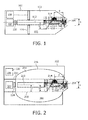
- Figure 1 displays an examplary device in the form of a capsule 102 comprising a reservoir 103.
- the capsule 102 is at made of a biocompatible plastic, such as a medical grade polyethylene.
- the reservoir 103 is provided with an orifice 104.
- the orifice 104 can be provided with a hydrophobic coating as to minimize a diffusion into the reservoir 103 of a humidity present in a moist environment surrounding the capsule 102.
- the reservoir 103 contains a reservoir's content 106 which is a powder like medication.
- An actuator arrangement comprises an actuator 107 and a further actuator 108.
- the actuator 107 which is a spring actuator, an electromagnetic actuator, a hydraulic actuator or a piezoelectric actuator, causes an auger 110 to rotate around an axis of revolution 112 during use.
- the auger 110 is made of a biocompatible plastic or a stainless steel and extends into the reservoir 103 in order to provide a mechanical interaction with the reservoir's content 106 with the purpose of both conveying the reservoir's content 106 to the orifice 104 and annulling a solidification of the reservoir's content 106.
- the solidification of the reservoir's content 106 is caused by way of a humidification in the moist environment surrounding the capsule 102 or by way of a humidity already contained in the reservoir's content 106.
- the solidification of the reservoir's content 106 is annulled by way of pulverization through a revolution of the auger 110 during use.
- the auger 110 is provided with a helical flighting 114.
- the helical flighting has a helical flighting height h which monotonically increases with an axial distance from the orifice 104. Proximal to the orifice 104, the helical flighting height h matches a size s of the orifice with the purpose of continuation of the auger 110 up to and including the orifice 104.
- the helical flighting 114 has a helical flighting pitch p which monotonically increases with an axial distance measured from the orifice 104.
- a piston 116 serves for pressurizing the reservoir's content 106.
- the piston 116 which is made of a biocompatible plastic or a stainless steel and is optionally provided with a non-sticky coating, is driveable by the further actuator 108.
- the further actuator 108 is an electromagnetic actuator or a hydraulic actuator.
- a measurement apparatus 120 comprising a revolution counter, serves for measuring a number of revolutions made by the auger 110.
- a measurement signal generated by the measurement apparatus 120 serves for controlling the actuator 107 and the further actuator 108.
- the number of revolutions made by the auger 110 provides a measurement for the amount of the reservoir's content 106 conveyed through the orifice 104.
- an inside surface of the reservoir 103 can be provided with a non-sticky coating whereas the helical flighting 114 of the auger 110 can be provided with certain roughness features.
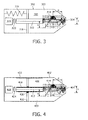
- Figure 2 displays an embodiment according to the invention in the form of a capsule 202 comprising a reservoir 203.
- the capsule 202 is made of a biocompatible plastic.
- the reservoir 203 is provided with an orifice 204.
- the reservoir 203 contains a reservoir's content 206 which is a powder like medication.
- An actuator arrangement 207 comprises an actuator 207 and a further actuator 208.
- the actuator 207 which is a spring actuator, an electromagnetic actuator, a hydraulic actuator or a piezoelectric actuator, causes an auger 210 to revolute during use around an axis of revolution 212.
- the auger 210 is provided in the reservoir 203 in order to provide mechanical interaction with the reservoir's content 206 with the purpose of both conveying the reservoir's content 206 to the orifice 204 and annulling a solidification of the reservoir's content 206.
- the auger 210 is provided with a helical flighting 214.
- the helical flighting has a helical flighting height h which monotonically increases with an axial distance from the orifice 204. Proximal to the orifice 204, the helical flighting height h matches a size s of the orifice with the purpose of continuation of the auger 210 up to and including the orifice 204.
- the helical flighting 214 has a helical flighting pitch p which monotonically increases with an axial distance from the orifice 204.
- a collapsible barrier 216 for pressurizing the reservoir's content 206 is contained in the reservoir 203. With that, under the pressure provided by the collapsible barrier 216, the reservoir's content 206 is continuously fed into the helical flighting 214 of the auger 210.
- the collapsible barrier 216 is conformable to a tube like grid 218 installed around the auger 210 which tube like grid 218 is to prevent the collapsible barrier 216 from contacting the auger 210. By choosing a radius r of the grid 218 minimally, i.e.
- the collapsible barrier 216 is compressible by the further actuator 208.
- the further actuator 208 comprises a cartridge 220 that releases an inert gas upon actuation in the volume established by the reservoir 203, the collapsible barrier 216 and a seal 222 as to provide a pressure to the collapsible barrier 216.
- a measurement apparatus 224 comprising a revolution counter, serves for measuring a number of revolutions made by the auger 210.
- a measurement signal generated by the measurement apparatus 224 serves for controlling the actuator 207 and the further actuator 208.
- Figure 3 displays another exemplary device in the form of a capsule 302 comprising a reservoir 303.
- the reservoir is provided with an orifice 304.
- the reservoir 303 contains a reservoir's content 306 which is a powder like medication.
- An actuator arrangement comprises an actuator 308.
- the actuator 308 causes an auger 310 to revolute around an axis of revolution 312 during use.
- the auger 310 is present in the reservoir 303 in order to provide a mechanical interaction with the reservoir's content 306 with the purpose of both conveying the reservoir's content 306 to the orifice 304 and annulling a solidification of the reservoir's content 306.
- the auger 310 is provided with a helical flighting 314.
- the helical flighting has a helical flighting height h which increases with an axial distance from the orifice 304. Proximal to the orifice 304, the helical flighting height h matches a size s of the orifice with the purpose of continuation of the auger 310 up to and including the orifice 304.
- the helical flighting 314 has a helical flighting pitch p which increases with an axial distance from the orifice 304.
- the piston 316 is pretensioned to the reservoir's content 306 by way a facility for pretensioning.
- the facility for pretensioning comprises an elastic mechanical spring 318.
- the facility for pretensioning the piston 316 to the reservoir's content 306 may alternatively comprise an air spring, a repulsive magnetic element or a combination thereof. Trough this, a continuous energizing of an actuator to provide a pressure to the reservoir's content 304 is prevented from.
- a measurement apparatus 320 comprising a revolution counter, serves for measuring a number of revolutions made by the auger 310.
- a measurement signal generated by the measurement apparatus 320 serves for controlling the actuator 308.
- Figure 4 displays a further exemplary device in the form of a capsule 402 comprising a reservoir 403.
- the reservoir is provided with an orifice 404.
- the orifice 404 can be provided with a hydrophobic coating as to minimize a diffusion into the reservoir 403 of a humidity present in a moist environment surrounding the capsule 402.
- the reservoir 403 contains a reservoir's content 406 which is a powder like medication.
- An actuator arrangement comprises an actuator 408.
- the actuator 408, which is a spring actuator, an electromagnetic actuator, a hydraulic actuator or a piezoelectric actuator, causes an auger 410 to rotate around an axis of revolution 412 during use.
- the auger 410 extends into the reservoir 403 with the purpose of providing a mechanical interaction with the reservoir's content 406.
- the auger 410 is provided with a helical flighting 414.
- the helical flighting has a helical flighting height h which increases with an axial distance from the orifice 404. Proximal to the orifice 404, the helical flighting height h matches a size s of the orifice with the purpose of continuation of the auger 110 up to and including the orifice 404.
- the helical flighting 414 has a helical flighting pitch p which increases with an axial distance from the orifice 404.
- a piston 416 serves for pressurizing the reservoir's content 406. The piston 416 for pressurizing the reservoir's content 406 is driveable by the auger 410.
- the auger 410 is supplied with an auger screw thread 418 for cooperation with a piston screw thread 420.
- a rail 422 is supplied to the reservoir 402 to accurately guide a displacement of the piston 416 and to prevent the piston 416 from rotating with the auger 410.
- a measurement apparatus 424 comprising a revolution counter is arranged for measuring a number of revolutions made by the auger 410.
- a measurement signal generated by the measurement apparatus 424 serves for controlling the actuator 408.
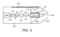
- Figure 5 displays an example in the form of a capsule 502 comprising a reservoir 503.
- the reservoir 503 is provided with an orifice 504.
- the reservoir 503 contains a reservoir's content 506 which is a powder like medication.
- An actuator arrangement comprises an actuator 508.
- the actuator 508 causes an auger 510 to revolute around an axis of revolution 512 during use.
- the auger 510 extends in the reservoir 503 in order to provide a mechanical interaction with the reservoir's content 506 with the purpose of both conveying the reservoir's content 506 to the orifice 504 and annulling a solidification of the reservoir's content 506.
- the auger 510 is provided with a helical flighting 514.
- a piston 516 for pressurizing the reservoir's content 506 is driveable by the auger 510. With that, under a pressure provided by the piston 516 during use, the reservoir's content 506 are continuously fed into the helical flighting 514 of the auger 510.
- the auger 510 is supplied with a constant helical flighting height h and a constant helical flighting pitch p.
- the helical flighting 514 is in cooperation with a piston screw thread 518.
- a rail 520 is supplied to the reservoir 502 to accurately guide a displacement of the piston 516 and to prevent the piston 516 from rotating with the auger 510.
- the piston 516 By driving the piston 516 through the auger 510, the prerequisite for a further actuator to drive the piston 516 is circumvented.
- the piston 516 has a surface profile 522 that corresponds to a reservoir's surface profile 524 adjacent to the orifice 504. Consequently, the piston 516 is transportable as far as the reservoir's orifice 504. As a result, a residue of the reservoir's content 506 is minimized.
- a measurement apparatus 526 comprising a revolution counter is arranged counting a number of revolutions made by the auger 510.
- a measurement signal generated by the measurement apparatus 526 is serving for controlling the actuator 508.
Landscapes
- Health & Medical Sciences (AREA)
- Engineering & Computer Science (AREA)
- Public Health (AREA)
- Life Sciences & Earth Sciences (AREA)
- Veterinary Medicine (AREA)
- Anesthesiology (AREA)
- Biomedical Technology (AREA)
- Heart & Thoracic Surgery (AREA)
- Hematology (AREA)
- General Health & Medical Sciences (AREA)
- Animal Behavior & Ethology (AREA)
- Bioinformatics & Cheminformatics (AREA)
- Chemical & Material Sciences (AREA)
- Medicinal Chemistry (AREA)
- Vascular Medicine (AREA)
- Infusion, Injection, And Reservoir Apparatuses (AREA)
- Medical Preparation Storing Or Oral Administration Devices (AREA)
- Medicinal Preparation (AREA)
Claims (10)
- Dispositif médical à mettre en place dans un environnement pour la distribution d'un médicament audit environnement, comprenant un réservoir (103) ayant un orifice (104), une unité de convoyage pour convoyer un contenu (106, 206, 306, 406, 506) du réservoir à travers l'orifice et un agencement actionneur pour entraîner l'unité de convoyage, dans lequel l'unité de convoyage comprend une vis d'Archimède (110, 210, 310, 410, 510) s'étendant dans le réservoir, caractérisé en ce que l'unité de convoyage comprend une barrière capable de s'effondrer (216) pour mettre sous pression le contenu du réservoir, et une grille semblable à un tube (218) installée autour de la vis d'Archimède, sur laquelle la barrière capable de s'effondrer est susceptible de se conformer.
- Dispositif selon la revendication 1, comprenant une cartouche (220) pour mettre sous pression la barrière capable de s'effondrer (216) lors de la libération d'un gaz inerte.
- Dispositif selon la revendication 1, dans lequel la vis d'Archimède a une hauteur de spire hélicoïdale (114, 214, 314, 414, 514) qui varie axialement.
- Dispositif selon la revendication 3, dans lequel la hauteur de spire hélicoïdale qui varie axialement augmente avec la distance axiale depuis l'orifice.
- Dispositif selon la revendication 4, dans lequel un rayon de la grille (218) est uniquement légèrement plus grand qu'un niveau maximum de la hauteur de spire hélicoïdale qui varie axialement.
- Dispositif selon la revendication 1, dans lequel la vis d'Archimède possède un pas de spire hélicoïdale qui varie axialement.
- Dispositif selon la revendication 6, dans lequel le pas de spire hélicoïdale qui varie axialement augmente de manière monotone avec la distance axiale depuis l'orifice.
- Dispositif selon la revendication 1, comprenant un appareil de mesure (120, 224, 320, 424, 526) pour mesurer une quantité du contenu du réservoir convoyé à travers l'orifice.
- Dispositif selon la revendication 8, dans lequel l'appareil de mesure comprend un compteur de rotations pour compter un nombre de rotations effectuées par la vis d'Archimède.
- Capsule (102, 202, 302, 402, 502) dotée du dispositif selon la revendication 1.
Applications Claiming Priority (2)
| Application Number | Priority Date | Filing Date | Title |
|---|---|---|---|
| US7377808P | 2008-06-19 | 2008-06-19 | |
| PCT/IB2009/052575 WO2009153739A1 (fr) | 2008-06-19 | 2009-06-17 | Dispositif d'administration de médicament sous forme de poudre dans un environnement humide |
Publications (2)
| Publication Number | Publication Date |
|---|---|
| EP2303361A1 EP2303361A1 (fr) | 2011-04-06 |
| EP2303361B1 true EP2303361B1 (fr) | 2015-02-25 |
Family
ID=41262149
Family Applications (1)
| Application Number | Title | Priority Date | Filing Date |
|---|---|---|---|
| EP09766276.1A Not-in-force EP2303361B1 (fr) | 2008-06-19 | 2009-06-17 | Capsule pour l'administration de médicament sous forme de poudre dans l'appareil digestif |
Country Status (5)
| Country | Link |
|---|---|
| US (1) | US9067011B2 (fr) |
| EP (1) | EP2303361B1 (fr) |
| JP (1) | JP5500600B2 (fr) |
| CN (1) | CN102065930B (fr) |
| WO (1) | WO2009153739A1 (fr) |
Families Citing this family (16)
| Publication number | Priority date | Publication date | Assignee | Title |
|---|---|---|---|---|
| US9642604B2 (en) | 2012-04-12 | 2017-05-09 | Phillips Medical Llc | Hemostatic system and its methods of use |
| US8845578B2 (en) * | 2013-02-28 | 2014-09-30 | Medtronic Xomed, Inc. | Biomaterial delivery device |
| US9724081B2 (en) * | 2013-06-04 | 2017-08-08 | Phillips Medical Llc | Hemostatic system and its methods of use |
| KR101914291B1 (ko) * | 2016-06-17 | 2018-11-01 | 윈비즈 주식회사 | 휴대용 분사장치 |
| US11541015B2 (en) | 2017-05-17 | 2023-01-03 | Massachusetts Institute Of Technology | Self-righting systems, methods, and related components |
| WO2018213579A1 (fr) | 2017-05-17 | 2018-11-22 | Massachusetts Institute Of Technology | Articles à auto-actionnement |
| GB201721065D0 (en) * | 2017-12-15 | 2018-01-31 | Ondosis Ab | Delivery device for drug pellets |
| AU2019269636A1 (en) | 2018-05-17 | 2020-11-19 | Massachusetts Institute Of Technology | Systems for electrical stimulation |
| EP4579371A3 (fr) | 2018-10-02 | 2025-12-24 | Boston Scientific Scimed, Inc. | Dispositifs de fluidisation et d'administration d'un agent pulverulent |
| CN113164722B (zh) | 2018-10-02 | 2023-04-11 | 波士顿科学国际有限公司 | 用于流化和输送粉状剂的装置 |
| GB201817978D0 (en) * | 2018-11-02 | 2018-12-19 | Ondosis Ab | Delivery device for drug pellets |
| EP4696361A3 (fr) | 2019-02-01 | 2026-04-15 | Massachusetts Institute of Technology | Systèmes et procédés d'injection de liquide |
| GB201908810D0 (en) * | 2019-06-19 | 2019-07-31 | Ondosis Ab | Delivery device for drug pellets |
| US11541216B2 (en) | 2019-11-21 | 2023-01-03 | Massachusetts Institute Of Technology | Methods for manufacturing tissue interfacing components |
| GB202004831D0 (en) * | 2020-04-01 | 2020-05-13 | Ondosis Ab | Delivery device for oral dosage forms |
| GB202007254D0 (en) * | 2020-05-15 | 2020-07-01 | Ondosis Ab | Delivery device for units of an oral dosage form |
Family Cites Families (51)
| Publication number | Priority date | Publication date | Assignee | Title |
|---|---|---|---|---|
| DE3317536A1 (de) * | 1983-05-13 | 1984-11-15 | Siemens AG, 1000 Berlin und 8000 München | Dosiervorrichtung fuer ein medikament |
| DE3339323C2 (de) | 1983-10-29 | 1986-01-30 | Busch, Ulrich, 2000 Hamburg | Transportkapsel für Rohrleitungssysteme |
| US4572403A (en) * | 1984-02-01 | 1986-02-25 | Rafael Benaroya | Timed dispensing device for tablets, capsules, and the like |
| US4814180A (en) * | 1984-03-21 | 1989-03-21 | Alza Corporation | Agent dispenser comprising a semipermeable wall surrounding single-piece or two-piece container |
| US5071040A (en) * | 1990-03-09 | 1991-12-10 | Pfizer Hospital Products Group, Inc. | Surgical adhesives mixing and dispensing implement |
| US5279607A (en) * | 1991-05-30 | 1994-01-18 | The State University Of New York | Telemetry capsule and process |
| US5318557A (en) * | 1992-07-13 | 1994-06-07 | Elan Medical Technologies Limited | Medication administering device |
| TW245642B (fr) | 1992-09-29 | 1995-04-21 | Alza Corp | |
| US5423779A (en) * | 1993-11-02 | 1995-06-13 | Yeh; Charles R. | High efficiency filtration particulate and smoke evacuator system |
| US5567592A (en) * | 1994-02-02 | 1996-10-22 | Regents Of The University Of California | Screening method for the identification of bioenhancers through the inhibition of P-glycoprotein transport in the gut of a mammal |
| US5803373A (en) * | 1997-03-10 | 1998-09-08 | Kimberly-Clark Worldwide, Inc. | Water-resistant roll towel dispenser |
| GB9718903D0 (en) | 1997-09-05 | 1997-11-12 | Glaxo Group Ltd | Method,compositions and kits for increasing the oral bioavailability of pharmaceutical agents |
| JP4065663B2 (ja) * | 1997-10-02 | 2008-03-26 | ボストン サイエンティフィック リミテッド | 繊維を体内へと送達するためのデバイス |
| GB9827200D0 (en) | 1998-12-11 | 1999-02-03 | Glaxo Group Ltd | Dry powder inhaler |
| US6300417B1 (en) * | 1998-12-22 | 2001-10-09 | The Texas A&M University System | Method for improving the impact resistance and scratch resistance of polymeric systems |
| DE60030283T2 (de) * | 1999-05-17 | 2007-09-20 | Cancer Research Ventures Ltd. | Zusammensetzungen zur erhöhung der bioverfügbarkeit von oral verabreichten pharmazeutischen verbindungen |
| FR2794654B1 (fr) | 1999-06-08 | 2001-10-19 | Ct De Transfert Des Microtechn | Dispositif de largage de substances dans un tube digestif |
| GB9930000D0 (en) * | 1999-12-21 | 2000-02-09 | Phaeton Research Ltd | An ingestible device |
| US6699214B2 (en) * | 2000-01-19 | 2004-03-02 | Scimed Life Systems, Inc. | Shear-sensitive injectable delivery system |
| CN1404388A (zh) * | 2000-01-20 | 2003-03-19 | 德尔西斯药品公司 | 多级药物剂型 |
| US8036731B2 (en) * | 2001-01-22 | 2011-10-11 | Spectrum Dynamics Llc | Ingestible pill for diagnosing a gastrointestinal tract |
| US6929636B1 (en) * | 2000-11-08 | 2005-08-16 | Hewlett-Packard Development Company, L.P. | Internal drug dispenser capsule medical device |
| WO2003008637A2 (fr) | 2001-07-17 | 2003-01-30 | Xanthus Life Sciences, Inc. | Utilisation du genotypage dans l'individualisation des therapies |
| JP4744026B2 (ja) * | 2001-07-30 | 2011-08-10 | オリンパス株式会社 | カプセル内視鏡およびカプセル内視鏡システム |
| FR2835730B1 (fr) | 2002-02-11 | 2004-12-10 | C T M Ct De Transfert Des Micr | Dispositif pour la delivrance de substances et le prelevement intracorporel |
| JP2003325439A (ja) * | 2002-05-15 | 2003-11-18 | Olympus Optical Co Ltd | カプセル型医療装置 |
| US20060155174A1 (en) * | 2002-12-16 | 2006-07-13 | Arkady Glukhovsky | Device, system and method for selective activation of in vivo sensors |
| AU2004208580A1 (en) | 2003-01-29 | 2004-08-12 | E-Pill Pharma Ltd. | Active drug delivery in the gastrointestinal tract |
| US7014640B2 (en) * | 2003-03-28 | 2006-03-21 | Depuy Products, Inc. | Bone graft delivery device and method of use |
| JP2004350963A (ja) * | 2003-05-29 | 2004-12-16 | Olympus Corp | カプセル型医療装置 |
| JP4332152B2 (ja) * | 2003-09-02 | 2009-09-16 | 富士通株式会社 | 薬服用状況管理方法及び薬剤 |
| US20050053648A1 (en) | 2003-09-08 | 2005-03-10 | Chalmers Anne Marie | Medication delivery device |
| WO2005038049A2 (fr) | 2003-10-06 | 2005-04-28 | Heinrich Guenther | Systeme et methode pour optimiser une pharmacotherapie |
| US7112774B2 (en) * | 2003-10-09 | 2006-09-26 | Avago Technologies Sensor Ip (Singapore) Pte. Ltd | CMOS stereo imaging system and method |
| JP4680939B2 (ja) * | 2004-02-10 | 2011-05-11 | シネコー・エルエルシー | 治療薬用脈管内送達システム |
| JP2008510558A (ja) * | 2004-08-27 | 2008-04-10 | コーニンクレッカ フィリップス エレクトロニクス エヌ ヴィ | 少なくとも1つの薬剤を投与する、電子制御され、遠隔制御されるピル及びシステム |
| EP1796776A1 (fr) | 2004-09-01 | 2007-06-20 | Koninklijke Philips Electronics N.V. | Comprime a commande electronique et systeme destine a administrer au moins un medicament |
| NZ554384A (en) | 2004-10-04 | 2010-04-30 | Sanofi Aventis Deutschland | Drive mechanism for drug delivery device |
| US20060078621A1 (en) | 2004-10-13 | 2006-04-13 | Wedinger Robert S | Method of providing customized drug delivery systems |
| EP1846060A1 (fr) * | 2004-11-10 | 2007-10-24 | Olympus Corporation | Appareil pouvant etre insere dans le corps humain |
| JP2008521794A (ja) | 2004-11-29 | 2008-06-26 | コーニンクレッカ フィリップス エレクトロニクス エヌ ヴィ | 少なくとも一の薬剤を輸送するための、少なくとも一のセンサを有する電子制御式の錠剤およびシステム |
| JP2008534028A (ja) | 2005-01-18 | 2008-08-28 | コーニンクレッカ フィリップス エレクトロニクス エヌ ヴィ | 摂取されたカプセルの通過を制御するシステムおよび方法 |
| AU2006213885A1 (en) * | 2005-02-09 | 2006-08-17 | Children's Medical Center Corporation | Device for mixing and delivering fluids for tissue repair |
| WO2006126653A1 (fr) * | 2005-05-27 | 2006-11-30 | Olympus Corporation | Dispositif d’introduction dans un sujet |
| ATE454185T1 (de) | 2005-11-03 | 2010-01-15 | Dentaco Gmbh | Appliziervorrichtung für eine fliessfähige substanz |
| US8728289B2 (en) * | 2005-12-15 | 2014-05-20 | Medtronic, Inc. | Monolithic electrodes and pH transducers |
| US8642060B2 (en) * | 2006-04-24 | 2014-02-04 | Warsaw Orthopedic, Inc. | Controlled release systems and methods for osteal growth |
| US20100063485A1 (en) | 2006-09-08 | 2010-03-11 | Koninklijke Philips Electronics N.V. | Device for the controlled release of a predefined quantity of a substance |
| WO2008038199A1 (fr) | 2006-09-25 | 2008-04-03 | Koninklijke Philips Electronics, N.V. | Appareil d'administration de médicament |
| JP5697871B2 (ja) | 2006-11-21 | 2015-04-08 | メディメトリクス ペルソナリズド ドルグ デリヴェリー ベー ヴェ | 薬物送達カプセル、及び生体内での薬剤送達又は診断システム |
| CN100534544C (zh) | 2006-12-26 | 2009-09-02 | 重庆大学 | 释药微电子胶囊 |
-
2009
- 2009-06-17 US US12/992,305 patent/US9067011B2/en not_active Expired - Fee Related
- 2009-06-17 JP JP2011514179A patent/JP5500600B2/ja not_active Expired - Fee Related
- 2009-06-17 EP EP09766276.1A patent/EP2303361B1/fr not_active Not-in-force
- 2009-06-17 CN CN200980122853.XA patent/CN102065930B/zh not_active Expired - Fee Related
- 2009-06-17 WO PCT/IB2009/052575 patent/WO2009153739A1/fr not_active Ceased
Also Published As
| Publication number | Publication date |
|---|---|
| US20110106064A1 (en) | 2011-05-05 |
| CN102065930A (zh) | 2011-05-18 |
| CN102065930B (zh) | 2013-05-22 |
| WO2009153739A1 (fr) | 2009-12-23 |
| JP2011524775A (ja) | 2011-09-08 |
| US9067011B2 (en) | 2015-06-30 |
| EP2303361A1 (fr) | 2011-04-06 |
| JP5500600B2 (ja) | 2014-05-21 |
Similar Documents
| Publication | Publication Date | Title |
|---|---|---|
| EP2303361B1 (fr) | Capsule pour l'administration de médicament sous forme de poudre dans l'appareil digestif | |
| US20180318496A1 (en) | Drug delivery device with compressible drug reservoir | |
| EP2086611B1 (fr) | Dispositif d'administration de médicament, capsule et système d'administration de médicament ou de diagnostic in vivo | |
| EP2484395A3 (fr) | Dispositif pour l'administration d'un médicament | |
| EP2526987A3 (fr) | Dispositif pour administrer un médicament | |
| EP1495781A3 (fr) | Méthode et dispositif pour délivrer de manière visée des agents médicaux où similaires | |
| EP2210635A3 (fr) | Appareil pour la fourniture de liquide et de matériaux à un sujet | |
| WO1991016884A1 (fr) | Systeme de diffusion de medicaments par doses multiples pulsees | |
| US20140214010A1 (en) | Drug delivery device with compressible fluid chambers | |
| CN107106765A (zh) | 给药液装置 | |
| EP2303391B1 (fr) | Pilule électronique comprenant une pluralité de réservoirs de médicament | |
| EP2817045B1 (fr) | Extrémité d'indicateur de dose | |
| US20040215171A1 (en) | Ingestible device for the release of substances at distinct locations in alimentary canal | |
| KR20030076666A (ko) | 액체 스트림 분사 장치 및 액체 스트림 분사 장치의 구동방법 | |
| EP3723836B1 (fr) | Dispositif d'administration intranasale | |
| US12296143B2 (en) | Liquid medicine administration device | |
| US20210283386A1 (en) | Medicine delivery and animal management systems | |
| JP7162055B2 (ja) | 薬液投与装置、および薬液投与装置の制御方法 | |
| EP3583034B1 (fr) | Procédé de remplissage de pointe et améliorations | |
| CN121866035A (zh) | 用于药剂的螺杆泵递送装置 | |
| EP1737376A1 (fr) | Dispositif d'injection dentaire | |
| HK1240870B (zh) | 给药液装置 | |
| WO2009144624A1 (fr) | Dispositif d'apport de médicament commandé | |
| HK1240870A1 (en) | Liquid drug administration device |
Legal Events
| Date | Code | Title | Description |
|---|---|---|---|
| PUAI | Public reference made under article 153(3) epc to a published international application that has entered the european phase |
Free format text: ORIGINAL CODE: 0009012 |
|
| 17P | Request for examination filed |
Effective date: 20110119 |
|
| AK | Designated contracting states |
Kind code of ref document: A1 Designated state(s): AT BE BG CH CY CZ DE DK EE ES FI FR GB GR HR HU IE IS IT LI LT LU LV MC MK MT NL NO PL PT RO SE SI SK TR |
|
| AX | Request for extension of the european patent |
Extension state: AL BA RS |
|
| DAX | Request for extension of the european patent (deleted) | ||
| RAP1 | Party data changed (applicant data changed or rights of an application transferred) |
Owner name: MEDIMETRICS PERSONALIZED DRUG DELIVERY B.V. |
|
| GRAP | Despatch of communication of intention to grant a patent |
Free format text: ORIGINAL CODE: EPIDOSNIGR1 |
|
| INTG | Intention to grant announced |
Effective date: 20140905 |
|
| GRAS | Grant fee paid |
Free format text: ORIGINAL CODE: EPIDOSNIGR3 |
|
| GRAA | (expected) grant |
Free format text: ORIGINAL CODE: 0009210 |
|
| AK | Designated contracting states |
Kind code of ref document: B1 Designated state(s): AT BE BG CH CY CZ DE DK EE ES FI FR GB GR HR HU IE IS IT LI LT LU LV MC MK MT NL NO PL PT RO SE SI SK TR |
|
| REG | Reference to a national code |
Ref country code: GB Ref legal event code: FG4D |
|
| REG | Reference to a national code |
Ref country code: CH Ref legal event code: EP |
|
| REG | Reference to a national code |
Ref country code: IE Ref legal event code: FG4D |
|
| REG | Reference to a national code |
Ref country code: DE Ref legal event code: R096 Ref document number: 602009029585 Country of ref document: DE Effective date: 20150409 |
|
| REG | Reference to a national code |
Ref country code: AT Ref legal event code: REF Ref document number: 711403 Country of ref document: AT Kind code of ref document: T Effective date: 20150415 |
|
| REG | Reference to a national code |
Ref country code: FR Ref legal event code: PLFP Year of fee payment: 7 |
|
| REG | Reference to a national code |
Ref country code: NL Ref legal event code: VDEP Effective date: 20150225 |
|
| REG | Reference to a national code |
Ref country code: AT Ref legal event code: MK05 Ref document number: 711403 Country of ref document: AT Kind code of ref document: T Effective date: 20150225 |
|
| REG | Reference to a national code |
Ref country code: LT Ref legal event code: MG4D |
|
| PG25 | Lapsed in a contracting state [announced via postgrant information from national office to epo] |
Ref country code: ES Free format text: LAPSE BECAUSE OF FAILURE TO SUBMIT A TRANSLATION OF THE DESCRIPTION OR TO PAY THE FEE WITHIN THE PRESCRIBED TIME-LIMIT Effective date: 20150225 Ref country code: NO Free format text: LAPSE BECAUSE OF FAILURE TO SUBMIT A TRANSLATION OF THE DESCRIPTION OR TO PAY THE FEE WITHIN THE PRESCRIBED TIME-LIMIT Effective date: 20150525 Ref country code: LT Free format text: LAPSE BECAUSE OF FAILURE TO SUBMIT A TRANSLATION OF THE DESCRIPTION OR TO PAY THE FEE WITHIN THE PRESCRIBED TIME-LIMIT Effective date: 20150225 Ref country code: FI Free format text: LAPSE BECAUSE OF FAILURE TO SUBMIT A TRANSLATION OF THE DESCRIPTION OR TO PAY THE FEE WITHIN THE PRESCRIBED TIME-LIMIT Effective date: 20150225 Ref country code: HR Free format text: LAPSE BECAUSE OF FAILURE TO SUBMIT A TRANSLATION OF THE DESCRIPTION OR TO PAY THE FEE WITHIN THE PRESCRIBED TIME-LIMIT Effective date: 20150225 Ref country code: SE Free format text: LAPSE BECAUSE OF FAILURE TO SUBMIT A TRANSLATION OF THE DESCRIPTION OR TO PAY THE FEE WITHIN THE PRESCRIBED TIME-LIMIT Effective date: 20150225 |
|
| PGFP | Annual fee paid to national office [announced via postgrant information from national office to epo] |
Ref country code: GB Payment date: 20150629 Year of fee payment: 7 Ref country code: DE Payment date: 20150629 Year of fee payment: 7 |
|
| PG25 | Lapsed in a contracting state [announced via postgrant information from national office to epo] |
Ref country code: GR Free format text: LAPSE BECAUSE OF FAILURE TO SUBMIT A TRANSLATION OF THE DESCRIPTION OR TO PAY THE FEE WITHIN THE PRESCRIBED TIME-LIMIT Effective date: 20150526 Ref country code: LV Free format text: LAPSE BECAUSE OF FAILURE TO SUBMIT A TRANSLATION OF THE DESCRIPTION OR TO PAY THE FEE WITHIN THE PRESCRIBED TIME-LIMIT Effective date: 20150225 Ref country code: AT Free format text: LAPSE BECAUSE OF FAILURE TO SUBMIT A TRANSLATION OF THE DESCRIPTION OR TO PAY THE FEE WITHIN THE PRESCRIBED TIME-LIMIT Effective date: 20150225 Ref country code: IS Free format text: LAPSE BECAUSE OF FAILURE TO SUBMIT A TRANSLATION OF THE DESCRIPTION OR TO PAY THE FEE WITHIN THE PRESCRIBED TIME-LIMIT Effective date: 20150625 |
|
| PGFP | Annual fee paid to national office [announced via postgrant information from national office to epo] |
Ref country code: FR Payment date: 20150617 Year of fee payment: 7 |
|
| PG25 | Lapsed in a contracting state [announced via postgrant information from national office to epo] |
Ref country code: NL Free format text: LAPSE BECAUSE OF FAILURE TO SUBMIT A TRANSLATION OF THE DESCRIPTION OR TO PAY THE FEE WITHIN THE PRESCRIBED TIME-LIMIT Effective date: 20150225 |
|
| PG25 | Lapsed in a contracting state [announced via postgrant information from national office to epo] |
Ref country code: EE Free format text: LAPSE BECAUSE OF FAILURE TO SUBMIT A TRANSLATION OF THE DESCRIPTION OR TO PAY THE FEE WITHIN THE PRESCRIBED TIME-LIMIT Effective date: 20150225 Ref country code: SK Free format text: LAPSE BECAUSE OF FAILURE TO SUBMIT A TRANSLATION OF THE DESCRIPTION OR TO PAY THE FEE WITHIN THE PRESCRIBED TIME-LIMIT Effective date: 20150225 Ref country code: DK Free format text: LAPSE BECAUSE OF FAILURE TO SUBMIT A TRANSLATION OF THE DESCRIPTION OR TO PAY THE FEE WITHIN THE PRESCRIBED TIME-LIMIT Effective date: 20150225 Ref country code: CZ Free format text: LAPSE BECAUSE OF FAILURE TO SUBMIT A TRANSLATION OF THE DESCRIPTION OR TO PAY THE FEE WITHIN THE PRESCRIBED TIME-LIMIT Effective date: 20150225 Ref country code: RO Free format text: LAPSE BECAUSE OF FAILURE TO SUBMIT A TRANSLATION OF THE DESCRIPTION OR TO PAY THE FEE WITHIN THE PRESCRIBED TIME-LIMIT Effective date: 20150225 |
|
| REG | Reference to a national code |
Ref country code: DE Ref legal event code: R097 Ref document number: 602009029585 Country of ref document: DE |
|
| PG25 | Lapsed in a contracting state [announced via postgrant information from national office to epo] |
Ref country code: PL Free format text: LAPSE BECAUSE OF FAILURE TO SUBMIT A TRANSLATION OF THE DESCRIPTION OR TO PAY THE FEE WITHIN THE PRESCRIBED TIME-LIMIT Effective date: 20150225 |
|
| PG25 | Lapsed in a contracting state [announced via postgrant information from national office to epo] |
Ref country code: IT Free format text: LAPSE BECAUSE OF FAILURE TO SUBMIT A TRANSLATION OF THE DESCRIPTION OR TO PAY THE FEE WITHIN THE PRESCRIBED TIME-LIMIT Effective date: 20150225 |
|
| PLBE | No opposition filed within time limit |
Free format text: ORIGINAL CODE: 0009261 |
|
| STAA | Information on the status of an ep patent application or granted ep patent |
Free format text: STATUS: NO OPPOSITION FILED WITHIN TIME LIMIT |
|
| PG25 | Lapsed in a contracting state [announced via postgrant information from national office to epo] |
Ref country code: MC Free format text: LAPSE BECAUSE OF FAILURE TO SUBMIT A TRANSLATION OF THE DESCRIPTION OR TO PAY THE FEE WITHIN THE PRESCRIBED TIME-LIMIT Effective date: 20150225 |
|
| REG | Reference to a national code |
Ref country code: CH Ref legal event code: PL |
|
| 26N | No opposition filed |
Effective date: 20151126 |
|
| PG25 | Lapsed in a contracting state [announced via postgrant information from national office to epo] |
Ref country code: LU Free format text: LAPSE BECAUSE OF FAILURE TO SUBMIT A TRANSLATION OF THE DESCRIPTION OR TO PAY THE FEE WITHIN THE PRESCRIBED TIME-LIMIT Effective date: 20150617 Ref country code: SI Free format text: LAPSE BECAUSE OF FAILURE TO SUBMIT A TRANSLATION OF THE DESCRIPTION OR TO PAY THE FEE WITHIN THE PRESCRIBED TIME-LIMIT Effective date: 20150225 |
|
| REG | Reference to a national code |
Ref country code: IE Ref legal event code: MM4A |
|
| PG25 | Lapsed in a contracting state [announced via postgrant information from national office to epo] |
Ref country code: LI Free format text: LAPSE BECAUSE OF NON-PAYMENT OF DUE FEES Effective date: 20150630 Ref country code: IE Free format text: LAPSE BECAUSE OF NON-PAYMENT OF DUE FEES Effective date: 20150617 Ref country code: CH Free format text: LAPSE BECAUSE OF NON-PAYMENT OF DUE FEES Effective date: 20150630 |
|
| PG25 | Lapsed in a contracting state [announced via postgrant information from national office to epo] |
Ref country code: BE Free format text: LAPSE BECAUSE OF FAILURE TO SUBMIT A TRANSLATION OF THE DESCRIPTION OR TO PAY THE FEE WITHIN THE PRESCRIBED TIME-LIMIT Effective date: 20150225 |
|
| PG25 | Lapsed in a contracting state [announced via postgrant information from national office to epo] |
Ref country code: MT Free format text: LAPSE BECAUSE OF FAILURE TO SUBMIT A TRANSLATION OF THE DESCRIPTION OR TO PAY THE FEE WITHIN THE PRESCRIBED TIME-LIMIT Effective date: 20150225 |
|
| REG | Reference to a national code |
Ref country code: DE Ref legal event code: R119 Ref document number: 602009029585 Country of ref document: DE |
|
| GBPC | Gb: european patent ceased through non-payment of renewal fee |
Effective date: 20160617 |
|
| REG | Reference to a national code |
Ref country code: FR Ref legal event code: ST Effective date: 20170228 |
|
| PG25 | Lapsed in a contracting state [announced via postgrant information from national office to epo] |
Ref country code: FR Free format text: LAPSE BECAUSE OF NON-PAYMENT OF DUE FEES Effective date: 20160630 Ref country code: DE Free format text: LAPSE BECAUSE OF NON-PAYMENT OF DUE FEES Effective date: 20170103 |
|
| PG25 | Lapsed in a contracting state [announced via postgrant information from national office to epo] |
Ref country code: GB Free format text: LAPSE BECAUSE OF NON-PAYMENT OF DUE FEES Effective date: 20160617 Ref country code: BG Free format text: LAPSE BECAUSE OF FAILURE TO SUBMIT A TRANSLATION OF THE DESCRIPTION OR TO PAY THE FEE WITHIN THE PRESCRIBED TIME-LIMIT Effective date: 20150225 Ref country code: HU Free format text: LAPSE BECAUSE OF FAILURE TO SUBMIT A TRANSLATION OF THE DESCRIPTION OR TO PAY THE FEE WITHIN THE PRESCRIBED TIME-LIMIT; INVALID AB INITIO Effective date: 20090617 |
|
| PG25 | Lapsed in a contracting state [announced via postgrant information from national office to epo] |
Ref country code: CY Free format text: LAPSE BECAUSE OF FAILURE TO SUBMIT A TRANSLATION OF THE DESCRIPTION OR TO PAY THE FEE WITHIN THE PRESCRIBED TIME-LIMIT Effective date: 20150225 |
|
| PG25 | Lapsed in a contracting state [announced via postgrant information from national office to epo] |
Ref country code: TR Free format text: LAPSE BECAUSE OF FAILURE TO SUBMIT A TRANSLATION OF THE DESCRIPTION OR TO PAY THE FEE WITHIN THE PRESCRIBED TIME-LIMIT Effective date: 20150225 |
|
| PG25 | Lapsed in a contracting state [announced via postgrant information from national office to epo] |
Ref country code: MK Free format text: LAPSE BECAUSE OF FAILURE TO SUBMIT A TRANSLATION OF THE DESCRIPTION OR TO PAY THE FEE WITHIN THE PRESCRIBED TIME-LIMIT Effective date: 20150225 Ref country code: PT Free format text: LAPSE BECAUSE OF FAILURE TO SUBMIT A TRANSLATION OF THE DESCRIPTION OR TO PAY THE FEE WITHIN THE PRESCRIBED TIME-LIMIT Effective date: 20150225 |