EP2303485B1 - Vorrichtung zum geraderichten von aufgrund übermässiger mechanischer spannung verformten metallelementen - Google Patents
Vorrichtung zum geraderichten von aufgrund übermässiger mechanischer spannung verformten metallelementen Download PDFInfo
- Publication number
- EP2303485B1 EP2303485B1 EP09750001.1A EP09750001A EP2303485B1 EP 2303485 B1 EP2303485 B1 EP 2303485B1 EP 09750001 A EP09750001 A EP 09750001A EP 2303485 B1 EP2303485 B1 EP 2303485B1
- Authority
- EP
- European Patent Office
- Prior art keywords
- actuator
- support element
- aforementioned
- tool
- counter
- Prior art date
- Legal status (The legal status is an assumption and is not a legal conclusion. Google has not performed a legal analysis and makes no representation as to the accuracy of the status listed.)
- Active
Links
Images


Classifications
-
- B—PERFORMING OPERATIONS; TRANSPORTING
- B21—MECHANICAL METAL-WORKING WITHOUT ESSENTIALLY REMOVING MATERIAL; PUNCHING METAL
- B21D—WORKING OR PROCESSING OF SHEET METAL OR METAL TUBES, RODS OR PROFILES WITHOUT ESSENTIALLY REMOVING MATERIAL; PUNCHING METAL
- B21D1/00—Straightening, restoring form or removing local distortions of sheet metal or specific articles made therefrom; Stretching sheet metal combined with rolling
- B21D1/06—Removing local distortions
- B21D1/10—Removing local distortions of specific articles made from sheet metal, e.g. mudguards
-
- B—PERFORMING OPERATIONS; TRANSPORTING
- B29—WORKING OF PLASTICS; WORKING OF SUBSTANCES IN A PLASTIC STATE IN GENERAL
- B29C—SHAPING OR JOINING OF PLASTICS; SHAPING OF MATERIAL IN A PLASTIC STATE, NOT OTHERWISE PROVIDED FOR; AFTER-TREATMENT OF THE SHAPED PRODUCTS, e.g. REPAIRING
- B29C53/00—Shaping by bending, folding, twisting, straightening or flattening; Apparatus therefor
- B29C53/16—Straightening or flattening
- B29C53/18—Straightening or flattening of plates or sheets
-
- B—PERFORMING OPERATIONS; TRANSPORTING
- B29—WORKING OF PLASTICS; WORKING OF SUBSTANCES IN A PLASTIC STATE IN GENERAL
- B29L—INDEXING SCHEME ASSOCIATED WITH SUBCLASS B29C, RELATING TO PARTICULAR ARTICLES
- B29L2031/00—Other particular articles
- B29L2031/30—Vehicles, e.g. ships or aircraft, or body parts thereof
- B29L2031/3055—Cars
Definitions
- the present invention relates to an apparatus for the straightening of deformed metal elements and / or plastics, or even damaged, as a result of excessive mechanical stress such as, for example, a shock, according to the preamble of claim 1.
- L The invention also relates to the corresponding method.
- Such an apparatus as well as such a method are for example described in the document FR-A-2755885 . It applies in particular, but not exclusively, to the recovery of an element of the bodywork of a deformed motor vehicle for example following an accident.
- the Applicant has proposed a method consisting in exerting on the deformed element a pressure generated by a cylinder, a balloon or the like, inflated by means of a fluid whose pressure is controlled.
- This method also involves two templates having the original shape of the deformed element that sandwich said deformed element. One of these templates is placed inside the deformed element while the other is placed outside of it.
- the invention therefore more particularly aims to solve this problem.
- the aforesaid actuator may be of pneumatic type and comprise a pneumatic cylinder, an inflatable balloon or bellows or the like.
- the invention applies in a particularly advantageous manner to the recovery of deformations of the roof (roof) of an automobile, in particular, but not exclusively, deformations due to hail: It is known that during certain storms, it is forms hailstones of relatively large dimensions whose impacts on a body cause a multiplicity of deformations in the form of bowls. The recovery of a body that has suffered such damage is very long and expensive: The price of the repair may be higher than the price of the vehicle, so that often the owner gives up repairing his car if he is not not properly insured.
- the extensible frame can be disposed inside the vehicle and suspended on the lateral reinforcements of the flag, substantially parallel to it.
- the counter bearing element carrying the actuator equipped with a template can be brought to the right of each deformation by sliding the cross member along the longitudinal members and the carriage along the cross member.
- the actuator is then supplied with fluid under pressure to allow the template to return the sheet to its original shape.
- This process can be easily repeated to correct all deformations on the pavilion. Given the nature of the deformations produced by hail, this type of straightening is enough to bring the pavilion back to its original form without having to carry out additional treatment. The cost of repair is therefore considerably reduced and becomes acceptable, even in the case of a vehicle of low value.
- This solution makes it possible to straighten elements that can not be straightened using conventional tools. Of course, it can be used for other parts (including vertical) of the body of a vehicle.
- the support element may comprise means of attachment to the body such as a suction cup or even a permanent magnet (or even an electromagnet) and a column on which can slide and lock a carriage on which is articulated a lever with a handle.
- a lever which constitutes the aforesaid connecting element, is slidably mounted a counter-support element on which can be fixed an actuator optionally equipped with a template.
- the lever may be of any order.
- the connecting element may comprise two branches articulated by one of their ends, these two branches carrying at their other ends two support pieces, at least one of which constitutes a template, an actuator being arranged between the two branches so that they can be rotated around the hinge axis.
- the apparatus is more particularly intended to straighten deformations produced on a roof or vehicle roof for example by large hail impacts.
- This apparatus involves an extensible frame 1 of square or rectangular shape intended to be arranged inside the vehicle, under the flag or the roof.
- the sides C 1 to C 4 of the frame 1 each comprise two sections T 1 , T 2 telescopically engaging one into the other, these sections T 1 , T 2 can be tubular or even consist of closed and / or open section profiles.
- Locking means may be used to lock the two sections making each side C 1 to C 4 to the desired length.
- an extensible cross member TE On two opposite sides of the frame 1 is slidably mounted an extensible cross member TE on which slides a carriage 6, the length of the crossmember adapting to the dimensions of the frame.
- this crosspiece TE comprises two tubular sections 7, 8 of rectangular section which fit telescopically in a third tubular section 9, the outer section of the sections 7 and 8 being slightly smaller than the inner section of the third section 9.
- This crossbar can be removable and be used independently of the frame to support an actuator / template assembly used in locations such as, for example, inside a car door.
- the carriage consists, in turn, of a profile section 10 substantially C-shaped delimiting a section volume slightly greater than the outer section of the section 9.
- This profile section 10 is provided on its face (core) opposite its longitudinal opening 11, with a threaded rod 12 oriented perpendicularly to the plane of the frame 1, on which a column 13 carrying a pneumatic actuator 14 can be fixed. Even directly the pneumatic actuator.
- the face of the actuator 14 opposite the column 13 is itself provided with a rod 15 which extends coaxially with the column 13 and which supports a template 16 for the recovery of the flag.
- the attachment of the frame on the rigid structure of the vehicle is obtained by means of four hooks 17 to 20 respectively arranged at the four corners of the frame 1.
- hooks 17 to 20 are intended to be introduced into holes or edges present in the structure or made specifically for this purpose.
- the hooks 17 to 20 may be replaced by adjustable length rods, cables or even chains.
- the attachment of these rods, cables or chains on the fixed structure of the vehicle can be achieved by any means of attachment and / or known attachment.
- this equipment is particularly effective: Once the frame 1 installed in the vehicle, the operator can bring all actuator 14 / template 16 in a suitable location (under deformation) by moving the extensible cross member TE along the sides and the carriage 6 along the crosspiece TE. After having made a height adjustment of this assembly, it proceeds to an admission of gas under pressure, preferably compressed air, into the actuator 14. Under the effect of the gas pressure, the template 16 comes to exert push on the deformation until it resumes its original shape.
- gas under pressure preferably compressed air
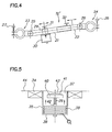
- the crosspiece TE may be articulated so as to allow changes in the orientation of the actuator 14 and a better adaptation of the template to the shape of the sheet that is to be straightened.
- FIG 4 shows a crosspiece TE 'comprising a central element formed by fitting two tubular sections 21, 22.
- the two ends of this central element are connected to guide elements and / or fixing 23, 24 via two respective hinges 25, 26.
- These guiding and / or fastening elements 23, 24 consist of a U-shaped section section section, the two ends of which are provided with bores in which clamping screws 27, 28 engage.
- a carriage 29 for carrying an actuator 30, for example of the type previously described.
- the axial locking of this carriage 29 as well as that of the two tubular sections is ensured by means of respective knurled screw screws 31, 32.
- the guiding and / or fixing elements 23, 24 may be slidably mounted on the two parallel sides of a frame 1 of the type shown in FIG. figure 1 or even a cradle, or even on the structure of the vehicle.
- the fixing in position of these guide elements 23, 24 on the frame or the cradle is obtained by tightening the screws 27, 28.
- the apparatus consists of an annular magnetized structure 34 (annular permanent magnet or one or more permanent magnets mounted on an annular structure).
- This annular element 34 carries a coaxial cylindrical drum 35 of outside diameter substantially equal to the inside diameter of the annular structure 34.
- This drum 35 comprises a bottom 36 and a circular opening 37 opposite the bottom 36, this opening 37 being located at height of the application face of the annular element 34.
- a bellows pneumatic cylinder 38 bearing on the bottom 36 and carrying, opposite the bottom 36, a rod 39 equipped with a jig 40 of circular shape provided with a face d 41 support slightly curved.
- the height adjustment of the template 40 is obtained thanks to the fact that the rod 39 is threaded in its lower part and is screwed into a threaded tubular sleeve 42 coaxial with the jack 38 and integral with the face thereof opposite the bottom.
- the annular element 34 is applied to the sheet, coaxially to the deformation 43.
- the template 40 After having optionally adjusted the position of the template 40 by screwing / unscrewing the rod 39 in the sleeve 42, it proceeds to a gas inlet pressure in the cylinder 38.
- the template 40 then exerts on the deformation 43 a force tending to straighten it. Because of its curved shape, the template 40 will bring the sheet slightly beyond its original position by creating within the sheet a tension likely to deploy any bends.
- the inlet of fluid under pressure in the cylinder 38 is interrupted, the part of sheet slightly convex (opposite the initial deformation), returns to its original position, thanks to its elasticity.
- the apparatus illustrated on the figure 5 can be mounted on a frame like the actuator shown on the figure 1 .
- the apparatus involves a lever 45 whose one end carries a handle 46 while the other end is hinged to a tubular sleeve 47 slidably mounted on a rod 48 integral with one end thereof, a suction cup 49 (or even a magnet or an electromagnet).
- a carriage 50 constituted by a tubular section on which can be fixed, via a fixing column 51, a pneumatic cylinder 52 carrying a template 53.
- the locking position of the trolley 50 on the lever 45 is provided by means of a needle screw 54 which is screwed into a threaded hole provided on the carriage 50.
- the suction cup 49 is fixed on a portion of sheet metal which may consist, but not necessarily, in the plate carrying the deformation.
- the actuator used in the previously described examples may be mounted on its support (counter-support element) via a ball joint.
- FIG. 6 This solution is illustrated on the figure 6 wherein the cylinder 60 (bellows type) is mounted in a tubular body 61 at least partially closed on one side by a bottom 62 secured to one end of the cylinder 60.
- the other end of the cylinder 60 is extended by a threaded rod 63 emerging from the body 61 by a coaxial orifice and on which can be screwed a template 64.
- the bottom 62 carries a threaded coaxial tubular sleeve 65 in which can be screwed rod 66 of a ball joint 67 providing a ball joint connection with a support piece 68, which may for example consist of a carriage of the type of those used in the previous examples.
- An advantage of this solution is that the operator can hold the tubular body by hand by having the hand protected by coaxial circular collars equipping the ends of said body.
- the apparatus illustrated on the figure 8 is specially designed to straighten deformations produced on a wing 70 of an automobile. It involves a lever 71 bent at right angles carrying at one end a handle 72 and at its other end, a template 73, possibly interchangeable (to adapt to the shape to straighten).
- This lever 71 is articulated at its elbow through a yoke 74 on a bearing piece 75 delimiting a concavity, for example a C-section piece in which can be engaged tightly the upper part of the tire 76 of the vehicle located at the level of the wing 70.
- the core 77 of this support piece 75 comprises, opposite the tire 76, a plate 78 which extends at right angles.
- an actuator 79 here an accordion cylinder, which acts on the arm 80 of the lever 71 carrying the jig 73.
- the operator To correct the deformation of the wing 70, the operator first has the support piece 75 on the tire 76 and the fixed there, possibly in the desired angular position, by means of not shown fastening. The cylinder 79 is then retracted. The operator then tilts the lever 71 until the template 73 comes to bear on the wing 70 in the region where the deformation is located: The operator then controls the activation of the cylinder 79 by holding the handle 72 until the deformed part is straightened.
- the previously described lever may be used without the jack or even without the support piece 75.
- the apparatus is in the form of an elongated clamp having two arms 81, 82 articulated to one another by one end (articulation 83). These two arms carry at their other ends two respective attachment means 84, 85 for receiving either a support element or a template (elements 86, 87).
- This clamp can be manipulated by a handle 88 carried by a third arm 89 articulated about the axis of the joint 83 of the arms 81, 82.
- a pneumatic actuator 90 consisting of an elastomeric balloon connected to a pressurized gas inlet circuit.
- this apparatus can be engaged in narrow passages, for example between the body sheet and the stiffeners associated with this sheet.
- the actuator may further comprise means for generating vibrations facilitating the return of the deformed sheet to its initial position.
- vibrations can be obtained by variable frequency percussion.
- the template can be mounted on the actuator via an attachment device easily connectable / disconnectable such as, for example, a velvet attachment and hook.
- the support element of the apparatus according to the invention may involve a plastic foam cushion bearing on a structural element of the vehicle.
- the density of the foam for example a polyurethane foam
- the density of the foam will be provided in such a way as to ensure transmission of the forces while conforming to the shape of the support piece. This gives a better distribution of the pressures exerted on this support piece.
- the stroke of the actuator will be shortened.
Landscapes
- Engineering & Computer Science (AREA)
- Mechanical Engineering (AREA)
- Straightening Metal Sheet-Like Bodies (AREA)
- Vehicle Cleaning, Maintenance, Repair, Refitting, And Outriggers (AREA)
- Automobile Manufacture Line, Endless Track Vehicle, Trailer (AREA)
Claims (25)
- Vorrichtung zum Geraderichten von Metallelementen, die infolge übermäßiger mechanischer Beanspruchung, wie beispielsweise Schlag, verformt wurden, des Typs umfassend mindestens ein Trägerelement (1), das mit temporären Mitteln zu Befestigung (17-20) an einer starren Struktur des Fahrzeugs und/oder seiner Karosserie ausgestattet ist, ein Gegenlagerelement, auf dem ein pneumatischer Aktor, der einen Zylinder (60) umfasst, befestigt werden kann, und eine positions- und/oder orientierungsregulierbare mechanische Verbindung zwischen dem Trägerelement (1) und dem Gegenlagerelement, wobei dieses Verbindungselement so ausgelegt ist, dass auf das Trägerelement (1) mindestens ein Bruchteil der durch den Aktor auf das Gegenlagerelement ausgeübten Belastung rückübertragen wird,
dadurch gekennzeichnet, dass die Vorrichtung eine magnetische Ringstruktur (34) umfasst, die eine zylindrische Trommel trägt, die einen Boden (36) und eine gegenüber dem Boden angeordnete kreisförmige Öffnung (37) entsprechend der Anbringfläche des Ringelements (34) umfasst, wobei diese Trommel den Aktor (38) beherbergt, der auf dem Boden (36) aufsitzt und gegenüber dem Boden einen Formkopf (40) trägt, wobei der Formkopf zum Ausüben eines Stoßes auf den vorspringenden Teil der Verformung (43) des geradezurichtenden Element vorgesehen ist, und dadurch, dass der oben genannte Aktor einen rohrförmigen Korpus umfasst, dessen Enden mit Flanschen versehen sind, die in der Hand gehalten werden können und zum Schutze der Hand des Anwenders dienen. - Vorrichtung nach einem der Ansprüche 1 oder 2,
dadurch gekennzeichnet, dass der oben genannte Aktor (38) einen pneumatischen Zylinder, einen Ballon oder einen Blasebalg oder Vergleichbares umfasst. - Vorrichtung nach Anspruch 1, dadurch gekennzeichnet, dass
der oben genannte Formkopf (40) auf dem Aktor (38) mit einem Gewindeschaft (39) montiert ist, der in eine Gewindemuffe (42) geschraubt ist, die mit einer dem Boden (36) gegenüberliegenden Fläche des Aktors fest verbunden ist. - Vorrichtung nach Anspruch 1,
dadurch gekennzeichnet, dass- das Trägerelement aus einem ausziehbaren Rahmen (1) besteht, umfassend zwei parallele Längsträger (C1, C2), wobei dieser Rahmen (1) mit Kopplungs- und/oder Aufhängemitteln (17-20) an die seitlichen Verstärkungen des Verdecks (Dachs) des Fahrzeugs ausgestattet ist;- das Bindungselement, das die regulierbare mechanische Bindung darstellt, eine auf zwei Abschnitten (T1, T2) von jedem Längsträger (C1, C2) des Trägerelements translatorisch bewegliche Querstrebe (TE) umfasst. - Vorrichtung nach Anspruch 4,
dadurch gekennzeichnet, dass das Gegenlagerelement eine Säule (13) umfasst, an deren einem Ende der Aktor (38) befestigt werden kann, und die an ihrem anderen Ende einen beweglichen, entlang der Querstrebe (TE) geführten Schlitten (6) umfasst. - Vorrichtung nach Anspruch 5,
dadurch gekennzeichnet, dass die Säule (13) längsregulierbar ist. - Vorrichtung nach Anspruch 4 bis 6,
dadurch gekennzeichnet, dass die oben genannten temporären Befestigungsmittel (17-20) an den vier Ecken des oben genannten Rahmens (1) angeordnet sind und Haken, längenregulierbare Schäfte, Kabel oder Ketten umfassen, die dazu geeignet sind, in Bohrungen oder Randabschlüsse einzugreifen, die in der starren Struktur des Fahrzeugs oder in seiner Karosserie vorhanden sind. - Vorrichtung nach Anspruch 4,
dadurch gekennzeichnet, dass die Seiten (C1-C4) des Rahmens (1) jeweils zwei Teilstücke (T1, T2) umfassen, die teleskopartig ineinandergreifen, wobei diese Teilstücke rohrförmig sein können oder auch aus Profilen mit geschlossenem und/offenem Querschnitt bestehen können. - Vorrichtung nach Anspruch 6,
dadurch gekennzeichnet, dass sie Arretiermittel umfasst, die zum Arretieren der beiden Teilstücke (T1, T2), die jeweils Seiten (C1-C4) realisieren, bei gewünschter Länge. geeignet sind. - Vorrichtung nach Anspruch 4,
dadurch gekennzeichnet, dass die oben genannte Querstrebe (TE) zwei rohrförmige Teilstücke (7, 8) mit rechteckigem Querschnitt umfasst, die in einem dritten rohrförmigen Teilstück (9) teleskopartig verschachtelt sind, wobei der äußere Querschnitt der Teilstücke (7 und 8) etwas kleiner ist als der innere Querschnitt des dritten Teilabschnitts (9), und dadurch, dass der Schlitten (6) einen Profilabschnitt (10) in Wesentlichen in C-Form umfasst, der ein Querschnittsvolumen begrenzt, das etwas größer ist als der äußere Querschnitt des Teilabschnitts (9). - Vorrichtung nach Anspruch 10,
dadurch gekennzeichnet, dass der Profilabschnitt (10), der den oben genannten Schlitten ausbildet, auf seiner Fläche (Kern) gegenüber seiner Längsöffnung (11) mit einem senkrecht zur Ebene des Rahmens (1) geachsten Gewindeschaft (12) versehen ist, auf dem eine Säule (13) befestigt werden kann, die den pneumatischen Aktor (38) trägt. - Vorrichtung nach Anspruch 4,
dadurch gekennzeichnet, dass die oben genannte Querstrebe (TE) in einer Weise gelenkig gelagert ist, dass Änderungen in der Ausrichtung des Aktors (38) und eine bessere Anpassung des Formkopfs an die Form des Blechs, dessen Geraderichten gewünscht ist, ermöglicht werden. - Vorrichtung nach Anspruch 12,
dadurch gekennzeichnet, dass die oben genannte Querstrebe ein mittiges Element umfasst, das durch Aufstecken von zwei rohrförmigen Teilstücken (21, 22) ausgebildet ist, wobei die beiden Enden dieses mittigen Elements über jeweils zwei Gelenke (25, 26) mit Führungs- und/oder Befestigungselementen (23, 24) verbunden sind. - Vorrichtung nach Anspruch 13,
dadurch gekennzeichnet, dass die oben genannten Führungs- und/oder Befestigungselemente (23, 24) im Wesentlichen eine U-Form aufweisen, deren beide Enden mit Bohrungen versehen sind, in die Feststellschrauben (27, 28) eingreifen. - Vorrichtung nach Anspruch 13,
dadurch gekennzeichnet, dass auf dem mittigen Element ein Schlitten (29) gleitend montiert ist, der dazu bestimmt ist, einen Aktor (30) zu tragen, wobei die axiale Blockierung dieses Schlittens (29) wie auch diejenige der beiden rohrförmigen Abschnitte jeweils mittels Stellschrauben mit Rändelkopf (31, 32) sichergestellt ist. - Vorrichtung nach einem der Ansprüche 4 bis 15,
dadurch gekennzeichnet, dass die oben genannte Querstrebe (TE) abnehmbar ist und so ausgelegt ist, dass sie unabhängig vom Rahmen (1) verwendet werden kann. - Vorrichtung nach einem der vorhergehenden Ansprüche,
dadurch gekennzeichnet, dass der oben genannte Formkopf (40) eine Auflagefläche (41) aufweist, die leicht gewölbt ist, derart, dass das geradezurichtende Blech über seine Urprungsposition hinaus gebracht wird. - Vorrichtung nach Anspruch 1,
dadurch gekennzeichnet, dass das Trägerelement (1) Befestigungsmittel an der Karosserie, wie eine Ansaugplatte (49) oder einen Permanentmagneten oder einen Elelctromagneten, umfasst, wobei diese Befestigungsmittel mit einer Säule (48) fest verbunden sind, auf der ein Schlitten (47), an dem ein mit einem Knauf (46) versehener Hebel (45) gelenkig befestigt ist, gleiten und arretiert werden kann, und dadurch, dass an diesem Hebel (45), der das oben genannte Verbindungselement aufbaut, ein Gegenlagerelement gleitend montiert ist, auf dem ein Aktor (52) befestigt werden kann, der gegebenenfalls mit einem Formkopf (53) ausgestattet sein kann. - Vorrichtung nach einem der vorhergehenden Ansprüche,
dadurch gekennzeichnet, dass der oben genannte Aktor (60) auf dem Gegenlagerelement (60) über eine Kugel/Pfanne-Verbindung (67) befestigt ist. - Vorrichtung nach einem der vorhergehenden Ansprüche,
dadurch gekennzeichnet, dass der Aktor Mittel umfasst, durch die sich Schwingungen so erzeugen lassen, dass die Rückkehr des Blechs in seine Anfangsposition erleichtert wird. - Vorrichtung nach Anspruch 20,
dadurch gekennzeichnet, dass die oben genannten Schwingungen durch Klopfen mit variabler Frequenz erhalten werden. - Vorrichtung nach einem der vorhergehenden Ansprüche,
dadurch gekennzeichnet, dass der Formkopf auf dem Aktor über eine leicht verbindbare/lösbare Befestigungsvorrichtung, wie eine Klettverschluss-Befestigung, befestigt ist. - Vorrichtung nach einem der vorhergehenden Ansprüche, dadurch gekennzeichnet, dass das Trägerelement ein Kunststoffschaumkissen umfasst, das dazu ausgelegt ist, sich an die Form eines Stützelements anzupassen und eine bessere Verteilung der Belastungen auf dieses Stützelement sicherzustellen.
- Verfahren zum Geraderichten von infolge einer übermäßigen mechanischen Beanspruchung, wie ein Schlag, verformten metallischen Elementen eines Fahrzeugs, dadurch gekennzeichnet, dass es die folgenden Schritte umfasst:- Bereitstellen einer Vorrichtung des Typs, der folgendes umfasst:- mindestens ein Trägerelement (1), das mit temporären Mitteln zur Befestigung (17-20) an der starren Struktur des Fahrzeugs und/oder seiner Karosserie ausgestattet ist;- ein Gegenlagerelement, auf dem ein pneumatischer Aktor (38), der einen Zylinder (60) umfasst, befestigt werden kann, und eine positions- und/oder orientierungsregulierbare mechanische Verbindung zwischen dem Trägerelement (1) und dem Gegenlagerelement, wobei dieses Verbindungselement so ausgelegt ist, dass auf das Trägerelement (1) mindestens ein Bruchteil der durch den Aktor auf das Gegenlagerelement ausgeübten Belastung rückübertragen wird; und- eine magnetische Ringstruktur (34), die eine zylindrische Trommel trägt, die einen Boden (36) und eine gegenüber dem Boden angeordnete kreisförmige Öffnung (37) entsprechend der Anbringfläche des Ringelements (34) umfasst, wobei diese Trommel den Aktor (38) beherbergt, der auf dem Boden (36) aufsitzt und gegenüber dem Boden einen Formkopf (40) trägt, wobei der Formkopf zum Ausüben eines Stoßes auf den vorspringenden Teil der Verformung (43) der geradezurichtenden Elemente vorgesehen ist, wobei der oben genannte Aktor einen rohrförmigen Korpus umfasst, dessen Enden mit Flanschen versehen sind, der von Hand gehalten werden kann und zum Schutze der Hand des Anwenders und des Formkopfes (40) mit leicht gewölbter Form dient;- temporäres Befestigen des Trägerelements (1) an der starren Struktur des Fahrzeugs und/oder seiner Karosserie;- Einstellen der Position des pneumatischen Aktors (38) anhand der regulierbaren mechanischen Verbindung zwischen dem Trägerelement und dem Gegenlagerelement, an dem der pneumatische Aktor befestigt ist, derart, dass der Formkopf (40) des Aktors den Druck auf den vorspringenden Teil einer Verformung (43) ausüben kann,- koaxiales Anbringen der magnetischen Ringstruktur (34) der Vorrichtung auf das Blech (44) an der Verformung,- Zuführen eines Druckgases in den Zylinder (60) des Aktors derart, dass der Druck auf den vorspringenden Teil ausgeübt wird,
- Verfahren nach Anspruch 24, dadurch gekennzeichnet, dass es den folgenden Schritt umfasst:- Betätigen von Schwingungsmitteln des Aktors derart, dass Schwingungen so erzeugt werden, dass die Rückkehr des Blechs in seinen Ausgangsposition erleichtert wird.
Applications Claiming Priority (2)
| Application Number | Priority Date | Filing Date | Title |
|---|---|---|---|
| FR0802465A FR2930737B1 (fr) | 2008-05-05 | 2008-05-05 | Appareillage pour le redresssement d'elements metalliques et/ou plastiques deformes a la suite d'une contrainte mecanique excessive |
| PCT/FR2009/000519 WO2009141520A2 (fr) | 2008-05-05 | 2009-04-30 | Appareillage pour le redressement d'elements metalliques et/ou plastiques deformes a la suite d'une contrainte mecanique excessive |
Publications (2)
| Publication Number | Publication Date |
|---|---|
| EP2303485A2 EP2303485A2 (de) | 2011-04-06 |
| EP2303485B1 true EP2303485B1 (de) | 2015-03-18 |
Family
ID=40120252
Family Applications (1)
| Application Number | Title | Priority Date | Filing Date |
|---|---|---|---|
| EP09750001.1A Active EP2303485B1 (de) | 2008-05-05 | 2009-04-30 | Vorrichtung zum geraderichten von aufgrund übermässiger mechanischer spannung verformten metallelementen |
Country Status (8)
| Country | Link |
|---|---|
| US (1) | US20110146362A1 (de) |
| EP (1) | EP2303485B1 (de) |
| JP (1) | JP2011522701A (de) |
| CN (1) | CN102015140A (de) |
| CA (1) | CA2723027A1 (de) |
| ES (1) | ES2536726T3 (de) |
| FR (1) | FR2930737B1 (de) |
| WO (1) | WO2009141520A2 (de) |
Families Citing this family (5)
| Publication number | Priority date | Publication date | Assignee | Title |
|---|---|---|---|---|
| CN102248032B (zh) * | 2011-06-10 | 2013-05-29 | 徐定善 | 变压器的矽钢片自动整平机 |
| CN104070324A (zh) * | 2014-06-30 | 2014-10-01 | 无锡市威海达机械制造有限公司 | 机械配件变形矫正的方法 |
| FR3028434B1 (fr) * | 2014-11-17 | 2017-04-21 | Frogs 2000 | Dispositif de redressage d'elements de carrosserie avec gabarits. |
| CN109550809B (zh) * | 2018-11-23 | 2020-03-13 | 中国航发南方工业有限公司 | 一种焊接件校正方法及装置 |
| US11834102B1 (en) * | 2021-03-29 | 2023-12-05 | Mitch Mundorf | Vehicle roof brace support apparatus |
Family Cites Families (21)
| Publication number | Priority date | Publication date | Assignee | Title |
|---|---|---|---|---|
| US1775968A (en) * | 1929-04-25 | 1930-09-16 | Nelson Samuel | Fender-straightening tool |
| US2531728A (en) * | 1947-12-27 | 1950-11-28 | Mary D Gersh | Shaping tool |
| US2588509A (en) * | 1948-04-12 | 1952-03-11 | Francis G Forster | Scissor type element for removing dents from body and fender panels |
| US2606469A (en) * | 1949-12-22 | 1952-08-12 | Gottlieb J Morgenthaler | Automobile body repair jack |
| US3091983A (en) * | 1962-02-01 | 1963-06-04 | Kliss Charles Joseph | Automobile body dent repair device |
| DE1452569A1 (de) * | 1964-06-23 | 1969-04-03 | Bosch Gmbh Robert | Transportables Schlaggeraet mit Motorantrieb zum Verformen von Blechteilen,insbesondere zum Ausbeulen von Autokarosserieteilen |
| US4174623A (en) * | 1977-09-08 | 1979-11-20 | Legrand Pierre N | Method and apparatus for reforming and straightening vehicles |
| US4404838A (en) * | 1981-07-23 | 1983-09-20 | Hare Charles E | System for straightening bent automobile bodies |
| US4510790A (en) * | 1981-07-23 | 1985-04-16 | Hare Charles E | Body and frame straightening system |
| US4745791A (en) * | 1986-09-22 | 1988-05-24 | Maker Manufacturing Company, Inc. | Portable kit assembly for straightening automobiles |
| IT1225886B (it) * | 1988-11-18 | 1990-12-07 | Francesco Fiorese | Attrezzatura per la riparazione di veicoli incidentati. |
| ZA937598B (en) * | 1992-10-28 | 1994-05-03 | Gordon Clifford Brown | Location method and panel pressing apparatus |
| DE19646101C2 (de) * | 1996-11-08 | 2000-07-27 | Weismann Jun | Verfahren zum Ausbeulen einer Delle aus einem Werkstück und Vorrichtung zur Durchführung des Verfahrens |
| FR2755885B1 (fr) * | 1996-11-18 | 1999-02-19 | Sarrion Sanchez Christian | Dispositif et procede pour redresser des elements metalliques et plastiques deformes |
| US6176113B1 (en) * | 1999-02-19 | 2001-01-23 | White, Iii Harold J. | Inflatable device for removing dents in components of vehicles |
| JP2001219217A (ja) * | 2000-02-09 | 2001-08-14 | Takeo Kamigaki | 車両修理装置 |
| DE10052364C2 (de) * | 2000-10-21 | 2003-06-26 | Jun Hans Weismann | Werkzeug zum Ausbeulen einer Delle z.B. aus Karosserieblechen oder zum Abziehen von Bauelementen, z.B. Firmenemblemen, von Karosserien |
| US6477884B1 (en) * | 2001-05-18 | 2002-11-12 | Kenneth Berntsen | Reciprocating saw blade repair device |
| FI111691B (fi) * | 2002-05-22 | 2003-09-15 | Autorobot Finland | Laite ajoneuvon pintapeltien oikaisemiseksi |
| JP4325977B2 (ja) * | 2002-11-08 | 2009-09-02 | 健男 上垣 | 板金修理支援装置用の治具 |
| US7520154B1 (en) * | 2007-02-14 | 2009-04-21 | Steven Anthony Pallotti | Fender and quarter; puller-popper (for auto body repair) |
-
2008
- 2008-05-05 FR FR0802465A patent/FR2930737B1/fr not_active Expired - Fee Related
-
2009
- 2009-04-30 CN CN2009801163323A patent/CN102015140A/zh active Pending
- 2009-04-30 JP JP2011507960A patent/JP2011522701A/ja active Pending
- 2009-04-30 CA CA2723027A patent/CA2723027A1/fr not_active Abandoned
- 2009-04-30 WO PCT/FR2009/000519 patent/WO2009141520A2/fr not_active Ceased
- 2009-04-30 ES ES09750001.1T patent/ES2536726T3/es active Active
- 2009-04-30 EP EP09750001.1A patent/EP2303485B1/de active Active
- 2009-04-30 US US12/991,193 patent/US20110146362A1/en not_active Abandoned
Also Published As
| Publication number | Publication date |
|---|---|
| CA2723027A1 (fr) | 2009-11-26 |
| WO2009141520A3 (fr) | 2010-01-14 |
| US20110146362A1 (en) | 2011-06-23 |
| CN102015140A (zh) | 2011-04-13 |
| EP2303485A2 (de) | 2011-04-06 |
| FR2930737B1 (fr) | 2010-09-03 |
| FR2930737A1 (fr) | 2009-11-06 |
| WO2009141520A2 (fr) | 2009-11-26 |
| ES2536726T3 (es) | 2015-05-28 |
| JP2011522701A (ja) | 2011-08-04 |
Similar Documents
| Publication | Publication Date | Title |
|---|---|---|
| EP2303485B1 (de) | Vorrichtung zum geraderichten von aufgrund übermässiger mechanischer spannung verformten metallelementen | |
| EP1502841B1 (de) | Frontendmodul für ein Fahrzeug mit Mitteln zum Einpassen der Leuchtenbaugruppe, Handwerkzeug für die Einstellung der Position und Montageverfahren für ein solches Frontend Modul | |
| EP2814640B1 (de) | Werkzeug zum montieren einer aufhängungs-blattfeder an den fahrzeugrahmen und den radträger einer fahrzeugachse eines kraftfahrzeugs und zu dessen demontage | |
| WO2015128594A1 (fr) | Unité robotique de transport de charges longues | |
| EP3909743A1 (de) | Anlage für den transport von vorformlingen, die mit einer vorrichtung zur winkligen positionierung der spindeln ausgestattet ist | |
| EP2535223A1 (de) | Anordnung der Montage- und Bedienungsmittel einer versenkbaren Trennwand | |
| EP2942237B1 (de) | Vorrichtung zur verankerung einer extremität einer dachreling für ein kraftfahrzeug, das mit längs-dachrelingen ausgestattet ist | |
| EP4311782B1 (de) | System zur handhabung einer seitenschale eines flugzeugs zur montage eines rumpfkörpers eines flugzeugs und verfahren zur montage eines rumpfkörpers eines flugzeugs | |
| FR2868036A1 (fr) | Dispositif de mise a l'eau et de recuperation d'un vehicule submersible | |
| FR2933949A1 (fr) | Dispositif de positionnement pour le montage du volet arriere sur la caisse d'un vehicule | |
| BE628783A (de) | ||
| FR3129185A1 (fr) | Dispositif de montage/démontage d’une goupille de liaison pour un assemblage bout à bout de deux éléments de charpente | |
| EP0464419A2 (de) | Vorrichtung zum Montieren und Demontieren von Blasformkästen in Schachtöfen | |
| EP1172283A1 (de) | Einstellbare Befestigung für Kunststoffteile, sowie Kotflügel und Flügel und für Kraftfahrzeuge | |
| FR3068328A1 (fr) | Diffuseur arriere mobile de vehicule automobile | |
| WO2006048527A1 (fr) | Dispositif de manutention destine a la pose et a la depose d'un element de carrosserie automobile | |
| EP1988006A1 (de) | Anordnung für die Montage eines Karosserieelements auf ein Element der Rahmenkonstruktion | |
| FR3142943A1 (fr) | Véhicule doté d’une bonbonne d’hydrogène à déformation contrôlée | |
| FR2955135A1 (fr) | Mat articule extensible a charniere demontable | |
| FR3098430A1 (fr) | Système de préhension par couplage magnétique | |
| FR2677927A1 (fr) | Dispositif pour atteler une remorque ou un appareil a un tracteur. | |
| FR2912940A1 (fr) | Dispositif et procede d'assistance et de realisation de travaux mecaniques sur une piece montee sur un support | |
| EP1092484A1 (de) | Handrichtwerkzeug für Fahrzeugkarosserie | |
| FR2907053A1 (fr) | Dispositif d'ouverture d'un ouvrant de vehicule automobile | |
| FR3025773A1 (fr) | Remorque avec plateforme de chargement abaissable et interchangeable |
Legal Events
| Date | Code | Title | Description |
|---|---|---|---|
| PUAI | Public reference made under article 153(3) epc to a published international application that has entered the european phase |
Free format text: ORIGINAL CODE: 0009012 |
|
| 17P | Request for examination filed |
Effective date: 20101202 |
|
| AK | Designated contracting states |
Kind code of ref document: A2 Designated state(s): AT BE BG CH CY CZ DE DK EE ES FI FR GB GR HR HU IE IS IT LI LT LU LV MC MK MT NL NO PL PT RO SE SI SK TR |
|
| AX | Request for extension of the european patent |
Extension state: AL BA RS |
|
| DAX | Request for extension of the european patent (deleted) | ||
| 17Q | First examination report despatched |
Effective date: 20120313 |
|
| GRAP | Despatch of communication of intention to grant a patent |
Free format text: ORIGINAL CODE: EPIDOSNIGR1 |
|
| INTG | Intention to grant announced |
Effective date: 20141008 |
|
| GRAS | Grant fee paid |
Free format text: ORIGINAL CODE: EPIDOSNIGR3 |
|
| GRAA | (expected) grant |
Free format text: ORIGINAL CODE: 0009210 |
|
| AK | Designated contracting states |
Kind code of ref document: B1 Designated state(s): AT BE BG CH CY CZ DE DK EE ES FI FR GB GR HR HU IE IS IT LI LT LU LV MC MK MT NL NO PL PT RO SE SI SK TR |
|
| REG | Reference to a national code |
Ref country code: GB Ref legal event code: FG4D Free format text: NOT ENGLISH |
|
| REG | Reference to a national code |
Ref country code: CH Ref legal event code: EP |
|
| REG | Reference to a national code |
Ref country code: IE Ref legal event code: FG4D Free format text: LANGUAGE OF EP DOCUMENT: FRENCH |
|
| REG | Reference to a national code |
Ref country code: AT Ref legal event code: REF Ref document number: 716211 Country of ref document: AT Kind code of ref document: T Effective date: 20150415 |
|
| REG | Reference to a national code |
Ref country code: DE Ref legal event code: R096 Ref document number: 602009030051 Country of ref document: DE Effective date: 20150430 |
|
| REG | Reference to a national code |
Ref country code: ES Ref legal event code: FG2A Ref document number: 2536726 Country of ref document: ES Kind code of ref document: T3 Effective date: 20150528 |
|
| REG | Reference to a national code |
Ref country code: NL Ref legal event code: VDEP Effective date: 20150318 |
|
| REG | Reference to a national code |
Ref country code: NL Ref legal event code: VDEP Effective date: 20150318 |
|
| PG25 | Lapsed in a contracting state [announced via postgrant information from national office to epo] |
Ref country code: FI Free format text: LAPSE BECAUSE OF FAILURE TO SUBMIT A TRANSLATION OF THE DESCRIPTION OR TO PAY THE FEE WITHIN THE PRESCRIBED TIME-LIMIT Effective date: 20150318 Ref country code: NO Free format text: LAPSE BECAUSE OF FAILURE TO SUBMIT A TRANSLATION OF THE DESCRIPTION OR TO PAY THE FEE WITHIN THE PRESCRIBED TIME-LIMIT Effective date: 20150618 Ref country code: SE Free format text: LAPSE BECAUSE OF FAILURE TO SUBMIT A TRANSLATION OF THE DESCRIPTION OR TO PAY THE FEE WITHIN THE PRESCRIBED TIME-LIMIT Effective date: 20150318 Ref country code: HR Free format text: LAPSE BECAUSE OF FAILURE TO SUBMIT A TRANSLATION OF THE DESCRIPTION OR TO PAY THE FEE WITHIN THE PRESCRIBED TIME-LIMIT Effective date: 20150318 Ref country code: LT Free format text: LAPSE BECAUSE OF FAILURE TO SUBMIT A TRANSLATION OF THE DESCRIPTION OR TO PAY THE FEE WITHIN THE PRESCRIBED TIME-LIMIT Effective date: 20150318 |
|
| REG | Reference to a national code |
Ref country code: AT Ref legal event code: MK05 Ref document number: 716211 Country of ref document: AT Kind code of ref document: T Effective date: 20150318 |
|
| REG | Reference to a national code |
Ref country code: LT Ref legal event code: MG4D |
|
| PG25 | Lapsed in a contracting state [announced via postgrant information from national office to epo] |
Ref country code: GR Free format text: LAPSE BECAUSE OF FAILURE TO SUBMIT A TRANSLATION OF THE DESCRIPTION OR TO PAY THE FEE WITHIN THE PRESCRIBED TIME-LIMIT Effective date: 20150619 Ref country code: LV Free format text: LAPSE BECAUSE OF FAILURE TO SUBMIT A TRANSLATION OF THE DESCRIPTION OR TO PAY THE FEE WITHIN THE PRESCRIBED TIME-LIMIT Effective date: 20150318 |
|
| PG25 | Lapsed in a contracting state [announced via postgrant information from national office to epo] |
Ref country code: NL Free format text: LAPSE BECAUSE OF FAILURE TO SUBMIT A TRANSLATION OF THE DESCRIPTION OR TO PAY THE FEE WITHIN THE PRESCRIBED TIME-LIMIT Effective date: 20150318 |
|
| PG25 | Lapsed in a contracting state [announced via postgrant information from national office to epo] |
Ref country code: RO Free format text: LAPSE BECAUSE OF FAILURE TO SUBMIT A TRANSLATION OF THE DESCRIPTION OR TO PAY THE FEE WITHIN THE PRESCRIBED TIME-LIMIT Effective date: 20150318 Ref country code: CZ Free format text: LAPSE BECAUSE OF FAILURE TO SUBMIT A TRANSLATION OF THE DESCRIPTION OR TO PAY THE FEE WITHIN THE PRESCRIBED TIME-LIMIT Effective date: 20150318 Ref country code: PT Free format text: LAPSE BECAUSE OF FAILURE TO SUBMIT A TRANSLATION OF THE DESCRIPTION OR TO PAY THE FEE WITHIN THE PRESCRIBED TIME-LIMIT Effective date: 20150720 Ref country code: SK Free format text: LAPSE BECAUSE OF FAILURE TO SUBMIT A TRANSLATION OF THE DESCRIPTION OR TO PAY THE FEE WITHIN THE PRESCRIBED TIME-LIMIT Effective date: 20150318 Ref country code: EE Free format text: LAPSE BECAUSE OF FAILURE TO SUBMIT A TRANSLATION OF THE DESCRIPTION OR TO PAY THE FEE WITHIN THE PRESCRIBED TIME-LIMIT Effective date: 20150318 |
|
| PG25 | Lapsed in a contracting state [announced via postgrant information from national office to epo] |
Ref country code: AT Free format text: LAPSE BECAUSE OF FAILURE TO SUBMIT A TRANSLATION OF THE DESCRIPTION OR TO PAY THE FEE WITHIN THE PRESCRIBED TIME-LIMIT Effective date: 20150318 Ref country code: MC Free format text: LAPSE BECAUSE OF FAILURE TO SUBMIT A TRANSLATION OF THE DESCRIPTION OR TO PAY THE FEE WITHIN THE PRESCRIBED TIME-LIMIT Effective date: 20150318 Ref country code: PL Free format text: LAPSE BECAUSE OF FAILURE TO SUBMIT A TRANSLATION OF THE DESCRIPTION OR TO PAY THE FEE WITHIN THE PRESCRIBED TIME-LIMIT Effective date: 20150318 Ref country code: IS Free format text: LAPSE BECAUSE OF FAILURE TO SUBMIT A TRANSLATION OF THE DESCRIPTION OR TO PAY THE FEE WITHIN THE PRESCRIBED TIME-LIMIT Effective date: 20150718 |
|
| REG | Reference to a national code |
Ref country code: CH Ref legal event code: PL |
|
| REG | Reference to a national code |
Ref country code: DE Ref legal event code: R097 Ref document number: 602009030051 Country of ref document: DE |
|
| PG25 | Lapsed in a contracting state [announced via postgrant information from national office to epo] |
Ref country code: IT Free format text: LAPSE BECAUSE OF FAILURE TO SUBMIT A TRANSLATION OF THE DESCRIPTION OR TO PAY THE FEE WITHIN THE PRESCRIBED TIME-LIMIT Effective date: 20150318 |
|
| PLBE | No opposition filed within time limit |
Free format text: ORIGINAL CODE: 0009261 |
|
| STAA | Information on the status of an ep patent application or granted ep patent |
Free format text: STATUS: NO OPPOSITION FILED WITHIN TIME LIMIT |
|
| REG | Reference to a national code |
Ref country code: IE Ref legal event code: MM4A |
|
| PG25 | Lapsed in a contracting state [announced via postgrant information from national office to epo] |
Ref country code: LI Free format text: LAPSE BECAUSE OF NON-PAYMENT OF DUE FEES Effective date: 20150430 Ref country code: DK Free format text: LAPSE BECAUSE OF FAILURE TO SUBMIT A TRANSLATION OF THE DESCRIPTION OR TO PAY THE FEE WITHIN THE PRESCRIBED TIME-LIMIT Effective date: 20150318 Ref country code: CH Free format text: LAPSE BECAUSE OF NON-PAYMENT OF DUE FEES Effective date: 20150430 |
|
| 26N | No opposition filed |
Effective date: 20151221 |
|
| PG25 | Lapsed in a contracting state [announced via postgrant information from national office to epo] |
Ref country code: SI Free format text: LAPSE BECAUSE OF FAILURE TO SUBMIT A TRANSLATION OF THE DESCRIPTION OR TO PAY THE FEE WITHIN THE PRESCRIBED TIME-LIMIT Effective date: 20150318 |
|
| REG | Reference to a national code |
Ref country code: FR Ref legal event code: PLFP Year of fee payment: 8 |
|
| PG25 | Lapsed in a contracting state [announced via postgrant information from national office to epo] |
Ref country code: IE Free format text: LAPSE BECAUSE OF NON-PAYMENT OF DUE FEES Effective date: 20150430 |
|
| PG25 | Lapsed in a contracting state [announced via postgrant information from national office to epo] |
Ref country code: MT Free format text: LAPSE BECAUSE OF FAILURE TO SUBMIT A TRANSLATION OF THE DESCRIPTION OR TO PAY THE FEE WITHIN THE PRESCRIBED TIME-LIMIT Effective date: 20150318 |
|
| REG | Reference to a national code |
Ref country code: FR Ref legal event code: PLFP Year of fee payment: 9 |
|
| PG25 | Lapsed in a contracting state [announced via postgrant information from national office to epo] |
Ref country code: BG Free format text: LAPSE BECAUSE OF FAILURE TO SUBMIT A TRANSLATION OF THE DESCRIPTION OR TO PAY THE FEE WITHIN THE PRESCRIBED TIME-LIMIT Effective date: 20150318 Ref country code: HU Free format text: LAPSE BECAUSE OF FAILURE TO SUBMIT A TRANSLATION OF THE DESCRIPTION OR TO PAY THE FEE WITHIN THE PRESCRIBED TIME-LIMIT; INVALID AB INITIO Effective date: 20090430 |
|
| PG25 | Lapsed in a contracting state [announced via postgrant information from national office to epo] |
Ref country code: CY Free format text: LAPSE BECAUSE OF FAILURE TO SUBMIT A TRANSLATION OF THE DESCRIPTION OR TO PAY THE FEE WITHIN THE PRESCRIBED TIME-LIMIT Effective date: 20150318 |
|
| PG25 | Lapsed in a contracting state [announced via postgrant information from national office to epo] |
Ref country code: TR Free format text: LAPSE BECAUSE OF FAILURE TO SUBMIT A TRANSLATION OF THE DESCRIPTION OR TO PAY THE FEE WITHIN THE PRESCRIBED TIME-LIMIT Effective date: 20150318 |
|
| PG25 | Lapsed in a contracting state [announced via postgrant information from national office to epo] |
Ref country code: LU Free format text: LAPSE BECAUSE OF NON-PAYMENT OF DUE FEES Effective date: 20150430 |
|
| REG | Reference to a national code |
Ref country code: FR Ref legal event code: PLFP Year of fee payment: 10 |
|
| PG25 | Lapsed in a contracting state [announced via postgrant information from national office to epo] |
Ref country code: MK Free format text: LAPSE BECAUSE OF FAILURE TO SUBMIT A TRANSLATION OF THE DESCRIPTION OR TO PAY THE FEE WITHIN THE PRESCRIBED TIME-LIMIT Effective date: 20150318 |
|
| REG | Reference to a national code |
Ref country code: FR Ref legal event code: PLFP Year of fee payment: 14 |
|
| PGFP | Annual fee paid to national office [announced via postgrant information from national office to epo] |
Ref country code: DE Payment date: 20250227 Year of fee payment: 17 |
|
| PGFP | Annual fee paid to national office [announced via postgrant information from national office to epo] |
Ref country code: ES Payment date: 20250509 Year of fee payment: 17 |
|
| PGFP | Annual fee paid to national office [announced via postgrant information from national office to epo] |
Ref country code: GB Payment date: 20260226 Year of fee payment: 18 |
|
| PGFP | Annual fee paid to national office [announced via postgrant information from national office to epo] |
Ref country code: BE Payment date: 20260226 Year of fee payment: 18 |
|
| PGFP | Annual fee paid to national office [announced via postgrant information from national office to epo] |
Ref country code: FR Payment date: 20260224 Year of fee payment: 18 |