EP2303650B1 - Serie de modeles de balai d'essuie-glace - Google Patents
Serie de modeles de balai d'essuie-glace Download PDFInfo
- Publication number
- EP2303650B1 EP2303650B1 EP09772247.4A EP09772247A EP2303650B1 EP 2303650 B1 EP2303650 B1 EP 2303650B1 EP 09772247 A EP09772247 A EP 09772247A EP 2303650 B1 EP2303650 B1 EP 2303650B1
- Authority
- EP
- European Patent Office
- Prior art keywords
- support
- wiper
- wiper blade
- longitudinal
- spring rails
- Prior art date
- Legal status (The legal status is an assumption and is not a legal conclusion. Google has not performed a legal analysis and makes no representation as to the accuracy of the status listed.)
- Active
Links
Images


Classifications
-
- B—PERFORMING OPERATIONS; TRANSPORTING
- B60—VEHICLES IN GENERAL
- B60S—SERVICING, CLEANING, REPAIRING, SUPPORTING, LIFTING, OR MANOEUVRING OF VEHICLES, NOT OTHERWISE PROVIDED FOR
- B60S1/00—Cleaning of vehicles
- B60S1/02—Cleaning windscreens, windows or optical devices
- B60S1/04—Wipers or the like, e.g. scrapers
- B60S1/32—Wipers or the like, e.g. scrapers characterised by constructional features of wiper blade arms or blades
- B60S1/38—Wiper blades
- B60S1/3848—Flat-type wiper blade, i.e. without harness
- B60S1/3874—Flat-type wiper blade, i.e. without harness with a reinforcing vertebra
- B60S1/3875—Flat-type wiper blade, i.e. without harness with a reinforcing vertebra rectangular section
- B60S1/3881—Flat-type wiper blade, i.e. without harness with a reinforcing vertebra rectangular section in additional element, e.g. spoiler
-
- B—PERFORMING OPERATIONS; TRANSPORTING
- B60—VEHICLES IN GENERAL
- B60S—SERVICING, CLEANING, REPAIRING, SUPPORTING, LIFTING, OR MANOEUVRING OF VEHICLES, NOT OTHERWISE PROVIDED FOR
- B60S1/00—Cleaning of vehicles
- B60S1/02—Cleaning windscreens, windows or optical devices
- B60S1/04—Wipers or the like, e.g. scrapers
- B60S1/32—Wipers or the like, e.g. scrapers characterised by constructional features of wiper blade arms or blades
- B60S1/38—Wiper blades
- B60S1/3806—Means, or measures taken, for influencing the aerodynamic quality of the wiper blades
- B60S1/381—Spoilers mounted on the squeegee or on the vertebra
-
- B—PERFORMING OPERATIONS; TRANSPORTING
- B60—VEHICLES IN GENERAL
- B60S—SERVICING, CLEANING, REPAIRING, SUPPORTING, LIFTING, OR MANOEUVRING OF VEHICLES, NOT OTHERWISE PROVIDED FOR
- B60S1/00—Cleaning of vehicles
- B60S1/02—Cleaning windscreens, windows or optical devices
- B60S1/04—Wipers or the like, e.g. scrapers
- B60S1/32—Wipers or the like, e.g. scrapers characterised by constructional features of wiper blade arms or blades
- B60S1/38—Wiper blades
- B60S1/3848—Flat-type wiper blade, i.e. without harness
- B60S1/3849—Connectors therefor; Connection to wiper arm; Attached to blade
- B60S1/3851—Mounting of connector to blade assembly
- B60S1/3856—Gripping the blade
-
- B—PERFORMING OPERATIONS; TRANSPORTING
- B60—VEHICLES IN GENERAL
- B60S—SERVICING, CLEANING, REPAIRING, SUPPORTING, LIFTING, OR MANOEUVRING OF VEHICLES, NOT OTHERWISE PROVIDED FOR
- B60S1/00—Cleaning of vehicles
- B60S1/02—Cleaning windscreens, windows or optical devices
- B60S1/04—Wipers or the like, e.g. scrapers
- B60S1/32—Wipers or the like, e.g. scrapers characterised by constructional features of wiper blade arms or blades
- B60S1/38—Wiper blades
- B60S1/3848—Flat-type wiper blade, i.e. without harness
- B60S1/3849—Connectors therefor; Connection to wiper arm; Attached to blade
- B60S1/3851—Mounting of connector to blade assembly
- B60S1/3858—Mounting of connector to blade assembly with protrusions cooperating with holes
-
- B—PERFORMING OPERATIONS; TRANSPORTING
- B60—VEHICLES IN GENERAL
- B60S—SERVICING, CLEANING, REPAIRING, SUPPORTING, LIFTING, OR MANOEUVRING OF VEHICLES, NOT OTHERWISE PROVIDED FOR
- B60S1/00—Cleaning of vehicles
- B60S1/02—Cleaning windscreens, windows or optical devices
- B60S1/04—Wipers or the like, e.g. scrapers
- B60S1/32—Wipers or the like, e.g. scrapers characterised by constructional features of wiper blade arms or blades
- B60S1/38—Wiper blades
- B60S1/3848—Flat-type wiper blade, i.e. without harness
- B60S1/3886—End caps
- B60S1/3887—Mounting of end caps
- B60S1/3889—Mounting of end caps cooperating with holes in the vertebra
Definitions
- the invention is based on a wiper blade according to the preamble of claim 1.
- a series of a wiper blade is understood to mean wiper blades that resemble essential design features, in particular in their outer cross-sectional contours, while subordinate construction features, e.g. Connection elements or spring rails, different and adapted to the particular application.
- a wiper blade with a support made of plastic which has two wiper blade towards each other, extending in the longitudinal direction of the wiper blade in cross-section angled support rails to a wiper strip. These form a cross-section approximately rectangular space with a longitudinal gap and are used to hold a head strip of the wiper strip.
- On the support a spoiler made of plastic and at least one spring rail are provided. This is arranged in a longitudinal channel of the carrier or the spoiler.
- the carrier which is made of a harder material than the spoiler is with this over inwardly directed, angular support rails positively connected or is produced in one piece with the carrier in a single operation in a Mehrstoffxtrusions vide.
- the carrier projects along with the spring rail a distance beyond the end of the spoiler profile.
- the carrier has at the level of the longitudinal channel lateral support strips with lateral recesses, engage in the locking lugs of end caps. The end caps are guided on the support strips.
- two spring rails are arranged side by side, being partially disposed in longitudinal grooves of the beam separated by a partition, and partially in longitudinal guides of the spoiler comprising the spring rails on the outside.
- a wiper blade which has a longitudinal channel for a first spring rail in a head strip of its wiper strip.
- the header and the spring rail are covered laterally and from below by retaining rails of the spoiler.
- the spoiler has a further longitudinal channel for a further spring rail, which runs parallel to the first spring rail and is shorter than this.
- the spring rails may have a cross section which varies over the length of the spring rails in its width and / or height.
- a wiper blade which consists of a respective wiper strip a carrier, two spring rails, which are housed in longitudinal channels of the carrier parallel to each other, two end caps and a connection element, wherein the spring rails do not project laterally from the longitudinal channels.
- a wiper blade each of which is a wiper strip, a carrier, two spring rails which are housed in longitudinal channels of the carrier parallel to each other and constructed a connection element, wherein the spoiler is glued to the carrier and in the central region has a recess for a connection element.
- the wiper blade is part of a series in which the individual wiper blades of the series differ in the same outer cross-sectional contours by the cross-sectional areas of the longitudinal channels and the spring rails.
- series of wiper blades are created, which differ only slightly or not in their outer appearance, but are adapted due to the different cross-sectional areas of the spring rails in their spring characteristic of the individual application.
- the longitudinal channels of the carrier run side by side and are separated by a partition wall.
- the widths of the spring rails of the individual wiper blades of the series are different while maintaining the width of the carrier by the strength of the partition is adjusted accordingly.
- the partition wall is correspondingly narrower, with narrower spring rails correspondingly wider.
- the longitudinal channels can be closed to the outside or open.
- the spring rails are not provided laterally from the longitudinal channels, so that the widths of the wiper blades within the series are the same.
- the spring rails are housed one above the other in a longitudinal channel which is divided by longitudinal ribs on the inner sides of its side walls in height, so that the spring rails are separated from each other in their freedom of movement.
- the thicknesses of the spring rails of the individual wiper blades of the series differ from each other, wherein the wall thicknesses of the top wall, the longitudinal ribs and / or the lower boundary wall of the longitudinal channel while maintaining the outer cross-sectional contours, in particular the widths are adjusted accordingly. For larger thicknesses of the spring rails, the wall thicknesses are reduced accordingly.
- the carriers may have on the side facing the wiper strip angled retaining rails whose free legs engage in longitudinal grooves of a head strip of the wiper strip.
- the wiper strip and the spoiler are formed in a two-material extrusion process on the carrier of a harder material. Due to the inventive design of the wiper blades of the series in this case, the wiper blades can be produced inexpensively in an extrusion process with only minor changes of the tool.
- a window for a connecting element is cut out of the spoiler in the central area except for the carrier.
- the wiper blades of a series can be combined with different connection elements and end caps.
- the connecting element has a central part, on which lateral feet are formed, which engage around the carrier laterally and from below and engage with at least two projections on opposite feet in corresponding recesses of the carrier or the spring rail.
- Such a connection element is expediently combined with a cover which laterally surrounds the carrier in the region of the window with side walls, wherein guide blocks on the inner sides of the side walls engage in lateral recesses and the spring rails are inserted in guide grooves of the guide blocks.
- the cover is locked by the spring rails in the recesses of the carrier.
- connection element which is constructed as the cover, but in addition bearing elements, such as a bearing pin or a hub for articulating with a wiper arm.
- the carrier has outer ribs on the outer sides of its side walls. These have open recesses to the side.
- the matching connection element comprises with its feet the side walls of the carrier. In the area of the recesses of the outer ribs recesses are also provided on the feet, which include webs between them. The webs fit in the assembled state in the recesses of the outer ribs and fill them out, so that the connection element is fixed to the carrier.
- the connecting element can be clipped onto the outer ribs transversely to the longitudinal direction of the carrier.
- the series according to the invention has wiper blades with spring rails lying one above the other, it is advantageous that the lower spring rail is longer than the upper spring rail and projects somewhat out of the carrier and into the end cap.
- locking cams of the end caps engage punch holes at the ends of the bottom rail.
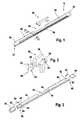
- FIG. 1 illustrated wiper blade 10 of a series comprises a wiper strip 12, a carrier 24, a spoiler 44 and two end caps 50 and two serving as a support element spring rails 40.
- parallel, angular support rails 26 are integrally formed, whose free, mutually facing legs 28 a Form longitudinal gap 32.
- the space 41 enclosed by the support rails 26 and the boundary wall 39 serves to receive a head strip 20 of the wiper strip 12, wherein the free legs 28 engage in longitudinal grooves 30 on both sides of a web 22.
- the web 22 connects the header 20 with support strips 18, which in turn are connected via a tilting web 16 with a wiper lip 14 of the wiper strip 12.
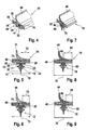
- the Fig. 5 to 9 show different wiper blades 10 of a series. They essentially have the same cross-sectional contour. In particular, they have a same width 70 while differing in the width of their spring rails 40. The different widths are compensated by differently wide partitions 74 and 86, so that the widths do not change despite the different widths 72 and 84 of the spring rails 40.
- the execution of the wiper blade 10 after Fig. 7 to 9 differs from the execution 4 to 6 in that a wiper strip 78 is integrally formed with a head strip 80 in a multi-material extrusion process on the carrier 76. Further, the carrier 76 has laterally open longitudinal channels 82 into which the spring rails 40 are inserted without protruding outwardly. Thus, the width 70 of the carrier 76 and thus of the wiper blade 10 is determined by the largest extension of the carrier 76 transversely to the longitudinal direction of the wiper blade 10.
- the spring rails 40 have at their ends on the outer side recesses 42, engage in the inner, non-visible cams of the end caps 50 when they during installation in mounting direction 52 on the end of the wiper strip 12th and the carrier 24 are pushed.
- the spoiler 44 and the carrier 24 each have at the ends of a cutout 48, which leaves only a central part of the carrier, so above the top wall 38 of the spoiler 44 is separated in this area, and the longitudinal channels 34 to about are cut to the support rails 26 so that the ends of the spring rails 40 are half open to the outsides.
- a window 46 is cut out of the spoiler 44 up to the carrier 24 in order to be able to attach a connection element 56.
- the connecting element 56 has a central part 58 which extends in the longitudinal direction of the wiper blade 10 and the lateral claws 60 includes the carrier 24, wherein lower legs 64 of the claws 60 abut against the boundary wall 39 of the carrier 24, while upper legs 62 projecting over Force application points 68 abut the top wall 38.
- projections 66 are provided on the inner sides, which engage in corresponding recesses 54 and fix the connecting element 56 in the longitudinal direction.
- the recesses 54 are arranged on the carrier 24 in the region of the window 46.
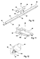
- the window 46 in the spoiler 44 is lined by a cover 90 which is placed in the mounting direction 92 on the carrier 24.
- the cover 90 has on the inner sides of its side walls 98, which connects a top wall 96 with each other, guide blocks 100 which face each other in pairs and in the longitudinal direction of the wiper blade 10 each have a guide groove 102.
- the guide blocks 100 are in mounting direction 92 in recesses 88 pushed on the sides of the carrier 24 until the guide grooves 102 coincide with the longitudinal channels 34 of the carrier 24. In this position, the spring rails 40 are inserted and pushed by the guide grooves 102. As a result, the cover 90 is locked and fixed to the carrier 24.
- the cover In the longitudinal direction, the cover is secured by the end faces of the guide blocks 100 in the recesses 88 of the carrier 24.
- the same fastening principle can also be used for a corresponding connection element which, in addition to the cover 90, has bearing elements in the form of a hub, bearing journals, bolts or the like.
- the cover 90 has at its ends connecting profiles 94 which overlap the spoiler 44 a piece far.
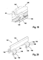
- the Fig. 13 to 20 show a series of wiper blades 104, in which two spring rails 122, 124 are housed one above the other in a longitudinal channel 112.
- the longitudinal channel 112 is divided in its height by longitudinal ribs 114 on the side walls 116, so that the lower spring rail 124 can move freely from the upper spring rail 122.
- the longitudinal channel 112 has except the side walls 116 a top wall 118, to which the spoiler 44 connects.
- the top wall 118 opposite is a boundary wall 138, on the outside of the wiper strip 12 toward two opposing, angled support rails 108 are formed.
- the support rails 108 form between them a longitudinal gap 110 and serve to receive the head strip 20 of the wiper strip 12.
- the wiper blades 104 after FIGS.
- the series 104 differ by their thickness 126 of the spring rails 122, 124.
- the smaller thickness of the spring rails 122, 124 after Fig. 15 is at the same outer dimensions, especially at the same Height 154, thereby allowing the longitudinal channel determining walls, namely the top wall 118, the lower boundary wall 138 and the inner longitudinal ribs 114 are correspondingly reinforced, while one or more of these walls 114, 118, 138 at thicker spring rails 122, 124 according to Fig. 16 be dimensioned correspondingly thinner.
- the carrier 106 has on the outer sides of its side walls 116 outer ribs 120 which extend approximately at the same height as the longitudinal ribs 114 on the inner sides of the side walls 116. By the outer ribs 120, the width 152 of the wiper blades 104 of this series is determined.
- the lower spring rail 124 and the wiper strip 12 protrude at the ends of the carrier 106 a little way out of this, while the upper spring rail 122 is shorter than the lower spring rail 124 and completely housed in the longitudinal channel 112.
- the lower spring rail 124 has a punch hole 128.
- a connecting element 140 is clipped onto the outer ribs 120 in the mounting direction 92.
- the connecting element 140 has feet 144 which, starting from a middle part 142 extending in the longitudinal direction of the wiper blade 104, laterally comprise the carrier 106.
- the feet 144 have at their approximately parallel to the central part 142 extending Legs 145 recesses 146, which form a web 148 between them.
- the webs 148 of the feet 144 engage in corresponding recesses 150 of the outer ribs 120 of the carrier 106, so that the connecting element 140 can be clipped onto the carrier 106.
- the outer ribs 120 which fit into the recesses 146, fix the connecting element 140 both in the longitudinal direction and in the mounting direction 92.
Landscapes
- Engineering & Computer Science (AREA)
- Mechanical Engineering (AREA)
- Physics & Mathematics (AREA)
- Fluid Mechanics (AREA)
- Quality & Reliability (AREA)
- Connection Of Plates (AREA)
- Turbine Rotor Nozzle Sealing (AREA)
- Extrusion Moulding Of Plastics Or The Like (AREA)
Claims (8)
- Balai d'essuie-glace (10, 104), constitué d'une raclette de balai d'essuie-glace (12), d'un support (24, 76, 106), de deux rails élastiques (40, 122, 124), qui sont montés parallèlement l'un à l'autre dans des canaux longitudinaux (34, 82, 112) du support (24, 76, 106), de deux embouts d'extrémité (50, 130) et d'un élément de raccordement (56, 140), caractérisé en ce qu'il fait partie d'une série de modèles, dans laquelle les balais d'essuie-glace individuels (10, 104) de la série de modèles, présentant les mêmes contours extérieurs en section transversale, se distinguent par les surfaces en section transversale des canaux longitudinaux (34, 82, 112) et des rails élastiques (40, 122, 124), et les rails élastiques (122, 124) sont montés l'un au-dessus de l'autre dans un canal longitudinal (112) qui est divisé en hauteur par des arêtes longitudinales (114) au niveau des côtés internes de ses parois latérales (116), les épaisseurs des rails élastiques (122, 124) des balais d'essuie-glace individuels (10) étant différentes les unes des autres et les épaisseurs de paroi d'une paroi de recouvrement (118), des arêtes longitudinales (114) et/ou de la paroi de limitation inférieure (138) du canal longitudinal (112) étant adaptées en conséquence en conservant les contours extérieurs en section transversale, en particulier les largeurs (152) et les hauteurs (153).
- Balai d'essuie-glace (10, 104) selon la revendication 1, caractérisé en ce que le support (24, 76) possède, sur le côté tourné vers la raclette de balai d'essuie-glace (12), des rails de retenue coudés (26), dont les branches libres (28) s'engagent dans des rainures longitudinales (30) d'une raclette de tête (20) de la raclette de balai d'essuie-glace (12).
- Balai d'essuie-glace (10, 104) selon l'une quelconque des revendications précédentes, caractérisé en ce que la raclette de balai d'essuie-glace (78) et un déflecteur (44) sont façonnés en un matériau relativement dur dans un procédé d'extrusion à deux matériaux sur le support (76).
- Balai d'essuie-glace (10, 104) selon l'une quelconque des revendications précédentes, caractérisé en ce que les surfaces en section transversale des canaux longitudinaux (34, 82, 112) et des rails élastiques (40, 122, 124) se distinguent par rapport à d'autres balais d'essuie-glace (10, 104) de la série de modèles, et un déflecteur (44) est façonné dans un procédé d'extrusion à deux matériaux sur le support (24, 76, 106), et dans la région centrale, une fenêtre (46) pour un élément de raccordement (56, 140) est découpée dans le déflecteur (44) à l'exception du support (24, 76, 106).
- Balai d'essuie-glace (10, 104) selon la revendication 4, caractérisé en ce que l'élément de raccordement (56) possède une partie centrale (58), sur laquelle sont façonnées des griffes latérales (60) qui viennent en prise latéralement et par le dessous autour du support (56) et qui s'engagent avec au moins deux saillies (66) au niveau de griffes mutuellement opposées (60) dans des évidements correspondants (54) du support (24) ou des rails élastiques (40).
- Balai d'essuie-glace (10, 104) selon la revendication 4, caractérisé en ce qu'un recouvrement (90) avec des parois latérales (98) entoure latéralement le support (24) dans la région de la fenêtre (46), des blocs de guidage (100) venant en prise dans des évidements latéraux (88) au niveau des côtés internes des parois latérales (98) et les rails élastiques (40) étant insérés dans des rainures de guidage (102) des blocs de guidage (100).
- Balai d'essuie-glace (10, 104) selon la revendication 4, caractérisé en ce que le support (106) présente des arêtes extérieures (120) au niveau des côtés extérieurs de ses parois latérales (116) et l'élément de raccordement (140) entoure latéralement le support (106) avec ses bases (144) et présente, au niveau des bases (144), des premiers évidements (146), des nervures (148) s'adaptant dans l'état monté entre les premiers évidements (146) dans des deuxièmes évidements (150) des arêtes extérieures (120).
- Balai d'essuie-glace (104) comprenant des rails élastiques (122, 124) disposés l'un au-dessus de l'autre selon la revendication 4, caractérisé en ce que le rail élastique inférieur (122) est plus long que le rail élastique supérieur (124) et fait saillie quelque peu hors du support (106) et pénètre dans les embouts d'extrémité (130), des cames d'encliquetage (134) des embouts d'extrémité (130) s'encliquetant dans des trous estampés (128) au niveau des extrémités du rail élastique inférieur (122).
Applications Claiming Priority (2)
| Application Number | Priority Date | Filing Date | Title |
|---|---|---|---|
| DE200810040033 DE102008040033A1 (de) | 2008-06-30 | 2008-06-30 | Baureihe eines Wischblatts |
| PCT/EP2009/056591 WO2010000547A2 (fr) | 2008-06-30 | 2009-05-29 | Série de modèles de balai d'essuie-glace |
Publications (2)
| Publication Number | Publication Date |
|---|---|
| EP2303650A2 EP2303650A2 (fr) | 2011-04-06 |
| EP2303650B1 true EP2303650B1 (fr) | 2013-10-30 |
Family
ID=40992554
Family Applications (1)
| Application Number | Title | Priority Date | Filing Date |
|---|---|---|---|
| EP09772247.4A Active EP2303650B1 (fr) | 2008-06-30 | 2009-05-29 | Serie de modeles de balai d'essuie-glace |
Country Status (3)
| Country | Link |
|---|---|
| EP (1) | EP2303650B1 (fr) |
| DE (1) | DE102008040033A1 (fr) |
| WO (1) | WO2010000547A2 (fr) |
Families Citing this family (4)
| Publication number | Priority date | Publication date | Assignee | Title |
|---|---|---|---|---|
| DE102010062902A1 (de) * | 2010-12-13 | 2012-06-14 | Robert Bosch Gmbh | Wischblattvorrichtung |
| CN103282246B (zh) | 2010-12-27 | 2015-09-30 | 株式会社美姿把 | 刮水器叶片 |
| DE102011078163A1 (de) * | 2011-06-28 | 2013-01-03 | Robert Bosch Gmbh | Wischblattvorrichtung |
| FR3028230B1 (fr) * | 2014-11-07 | 2018-03-02 | Valeo Systemes D'essuyage | Balai d’essuyage de vitres de vehicule automobile |
Family Cites Families (8)
| Publication number | Priority date | Publication date | Assignee | Title |
|---|---|---|---|---|
| DE19801058A1 (de) * | 1998-01-14 | 1999-07-15 | Bosch Gmbh Robert | Wischblatt zum Reinigen von Scheiben von Kraftfahrzeugen |
| DE20221548U1 (de) * | 2002-02-22 | 2006-06-14 | Robert Bosch Gmbh | Wischblatt zum Reinigen von Scheiben insbesondere von Kraftfahrzeugen |
| FR2851976B1 (fr) * | 2003-02-21 | 2007-11-09 | Bosch Gmbh Robert | Balai d'essuie-glace de vehicules automobiles |
| BRMU8402004U (pt) * | 2004-08-17 | 2004-12-28 | Dyna Electromecanica | Disposição introduzida em palheta |
| DE102005062462B4 (de) | 2005-12-27 | 2020-08-06 | Robert Bosch Gmbh | Wischblatt |
| DE102006020524A1 (de) | 2006-05-03 | 2007-11-08 | Robert Bosch Gmbh | Wischblatt |
| KR100732691B1 (ko) * | 2006-06-05 | 2007-06-27 | (주)에이치 에스 티 | 차량용 와이퍼 블레이드 |
| DE202007011262U1 (de) * | 2007-08-11 | 2007-10-18 | Ku, Yuan-Chin, Hsin-Chuang | Scheibenwischer |
-
2008
- 2008-06-30 DE DE200810040033 patent/DE102008040033A1/de not_active Withdrawn
-
2009
- 2009-05-29 EP EP09772247.4A patent/EP2303650B1/fr active Active
- 2009-05-29 WO PCT/EP2009/056591 patent/WO2010000547A2/fr not_active Ceased
Also Published As
| Publication number | Publication date |
|---|---|
| DE102008040033A1 (de) | 2009-12-31 |
| WO2010000547A3 (fr) | 2010-02-25 |
| WO2010000547A2 (fr) | 2010-01-07 |
| EP2303650A2 (fr) | 2011-04-06 |
Similar Documents
| Publication | Publication Date | Title |
|---|---|---|
| EP2054277B1 (fr) | Raclette d'essuie-glace | |
| EP2315687B1 (fr) | Balai d'essuie-glace avec un element de raccord | |
| EP2326538B1 (fr) | Dispositif de raccordement permettant de realiser une liaison articulee entre un balai d'essuie-glace et un bras d'essuie-glace | |
| EP2259954B1 (fr) | Raclette d essuie-glace | |
| EP2268513B1 (fr) | Balai d'essuie-glace | |
| EP1740424B1 (fr) | Raclette d'essuie-glace | |
| EP2079617B1 (fr) | Balai d'essuie-glace | |
| DE102005062462B4 (de) | Wischblatt | |
| EP2477853B1 (fr) | Balai d'essuie-glace à structure en forme de barre plate | |
| WO2009065648A1 (fr) | Raclette d'essuie-glace | |
| DE102004051466A1 (de) | Wischblatt | |
| WO2011061023A1 (fr) | Balai d'essuie-glace en forme de barre plate | |
| EP2450244A1 (fr) | Raclette d'essuie-glace | |
| WO2012113586A1 (fr) | Balai d'essuie-glace et embout | |
| EP2051883B1 (fr) | Raclette | |
| EP2303650B1 (fr) | Serie de modeles de balai d'essuie-glace | |
| EP2177407B1 (fr) | Elément de raccordement pour la liaison articulée d'une lame d'essuyage à un bras d'essuye-glace | |
| DE102004019158B4 (de) | Wischblatt | |
| DE102008001152B4 (de) | Wischblatt | |
| EP2097298B1 (fr) | Balai d'essuie-glace | |
| DE102004014598A1 (de) | Stoßverbinder zur Verbindung von Profilen | |
| EP2214936B1 (fr) | Balai d'essuie-glace | |
| DE202006004607U1 (de) | Rahmenkonstruktion für ein aus Rahmenholmen zusammengesetztes Bauelement | |
| WO2015000778A1 (fr) | Dispositif formant balai d'essuie-glace | |
| WO2013185968A1 (fr) | Procédé de fabrication d'un profilé d'essuie-vitre et profilé d'essuie-vitre fabriqué |
Legal Events
| Date | Code | Title | Description |
|---|---|---|---|
| PUAI | Public reference made under article 153(3) epc to a published international application that has entered the european phase |
Free format text: ORIGINAL CODE: 0009012 |
|
| 17P | Request for examination filed |
Effective date: 20110131 |
|
| AK | Designated contracting states |
Kind code of ref document: A2 Designated state(s): AT BE BG CH CY CZ DE DK EE ES FI FR GB GR HR HU IE IS IT LI LT LU LV MC MK MT NL NO PL PT RO SE SI SK TR |
|
| AX | Request for extension of the european patent |
Extension state: AL BA RS |
|
| DAX | Request for extension of the european patent (deleted) | ||
| 17Q | First examination report despatched |
Effective date: 20120705 |
|
| GRAP | Despatch of communication of intention to grant a patent |
Free format text: ORIGINAL CODE: EPIDOSNIGR1 |
|
| INTG | Intention to grant announced |
Effective date: 20130712 |
|
| GRAS | Grant fee paid |
Free format text: ORIGINAL CODE: EPIDOSNIGR3 |
|
| GRAA | (expected) grant |
Free format text: ORIGINAL CODE: 0009210 |
|
| AK | Designated contracting states |
Kind code of ref document: B1 Designated state(s): AT BE BG CH CY CZ DE DK EE ES FI FR GB GR HR HU IE IS IT LI LT LU LV MC MK MT NL NO PL PT RO SE SI SK TR |
|
| REG | Reference to a national code |
Ref country code: GB Ref legal event code: FG4D Free format text: NOT ENGLISH |
|
| REG | Reference to a national code |
Ref country code: CH Ref legal event code: EP |
|
| REG | Reference to a national code |
Ref country code: AT Ref legal event code: REF Ref document number: 638379 Country of ref document: AT Kind code of ref document: T Effective date: 20131115 |
|
| REG | Reference to a national code |
Ref country code: IE Ref legal event code: FG4D Free format text: LANGUAGE OF EP DOCUMENT: GERMAN |
|
| REG | Reference to a national code |
Ref country code: DE Ref legal event code: R096 Ref document number: 502009008256 Country of ref document: DE Effective date: 20131224 |
|
| REG | Reference to a national code |
Ref country code: NL Ref legal event code: VDEP Effective date: 20131030 |
|
| REG | Reference to a national code |
Ref country code: LT Ref legal event code: MG4D |
|
| PG25 | Lapsed in a contracting state [announced via postgrant information from national office to epo] |
Ref country code: NO Free format text: LAPSE BECAUSE OF FAILURE TO SUBMIT A TRANSLATION OF THE DESCRIPTION OR TO PAY THE FEE WITHIN THE PRESCRIBED TIME-LIMIT Effective date: 20140130 Ref country code: SE Free format text: LAPSE BECAUSE OF FAILURE TO SUBMIT A TRANSLATION OF THE DESCRIPTION OR TO PAY THE FEE WITHIN THE PRESCRIBED TIME-LIMIT Effective date: 20131030 Ref country code: IS Free format text: LAPSE BECAUSE OF FAILURE TO SUBMIT A TRANSLATION OF THE DESCRIPTION OR TO PAY THE FEE WITHIN THE PRESCRIBED TIME-LIMIT Effective date: 20140228 Ref country code: NL Free format text: LAPSE BECAUSE OF FAILURE TO SUBMIT A TRANSLATION OF THE DESCRIPTION OR TO PAY THE FEE WITHIN THE PRESCRIBED TIME-LIMIT Effective date: 20131030 Ref country code: HR Free format text: LAPSE BECAUSE OF FAILURE TO SUBMIT A TRANSLATION OF THE DESCRIPTION OR TO PAY THE FEE WITHIN THE PRESCRIBED TIME-LIMIT Effective date: 20131030 Ref country code: LT Free format text: LAPSE BECAUSE OF FAILURE TO SUBMIT A TRANSLATION OF THE DESCRIPTION OR TO PAY THE FEE WITHIN THE PRESCRIBED TIME-LIMIT Effective date: 20131030 Ref country code: FI Free format text: LAPSE BECAUSE OF FAILURE TO SUBMIT A TRANSLATION OF THE DESCRIPTION OR TO PAY THE FEE WITHIN THE PRESCRIBED TIME-LIMIT Effective date: 20131030 |
|
| PG25 | Lapsed in a contracting state [announced via postgrant information from national office to epo] |
Ref country code: ES Free format text: LAPSE BECAUSE OF FAILURE TO SUBMIT A TRANSLATION OF THE DESCRIPTION OR TO PAY THE FEE WITHIN THE PRESCRIBED TIME-LIMIT Effective date: 20131030 Ref country code: CY Free format text: LAPSE BECAUSE OF FAILURE TO SUBMIT A TRANSLATION OF THE DESCRIPTION OR TO PAY THE FEE WITHIN THE PRESCRIBED TIME-LIMIT Effective date: 20131030 Ref country code: LV Free format text: LAPSE BECAUSE OF FAILURE TO SUBMIT A TRANSLATION OF THE DESCRIPTION OR TO PAY THE FEE WITHIN THE PRESCRIBED TIME-LIMIT Effective date: 20131030 |
|
| PG25 | Lapsed in a contracting state [announced via postgrant information from national office to epo] |
Ref country code: PT Free format text: LAPSE BECAUSE OF FAILURE TO SUBMIT A TRANSLATION OF THE DESCRIPTION OR TO PAY THE FEE WITHIN THE PRESCRIBED TIME-LIMIT Effective date: 20140228 |
|
| PG25 | Lapsed in a contracting state [announced via postgrant information from national office to epo] |
Ref country code: EE Free format text: LAPSE BECAUSE OF FAILURE TO SUBMIT A TRANSLATION OF THE DESCRIPTION OR TO PAY THE FEE WITHIN THE PRESCRIBED TIME-LIMIT Effective date: 20131030 |
|
| REG | Reference to a national code |
Ref country code: DE Ref legal event code: R097 Ref document number: 502009008256 Country of ref document: DE |
|
| PG25 | Lapsed in a contracting state [announced via postgrant information from national office to epo] |
Ref country code: IT Free format text: LAPSE BECAUSE OF FAILURE TO SUBMIT A TRANSLATION OF THE DESCRIPTION OR TO PAY THE FEE WITHIN THE PRESCRIBED TIME-LIMIT Effective date: 20131030 Ref country code: CZ Free format text: LAPSE BECAUSE OF FAILURE TO SUBMIT A TRANSLATION OF THE DESCRIPTION OR TO PAY THE FEE WITHIN THE PRESCRIBED TIME-LIMIT Effective date: 20131030 Ref country code: SK Free format text: LAPSE BECAUSE OF FAILURE TO SUBMIT A TRANSLATION OF THE DESCRIPTION OR TO PAY THE FEE WITHIN THE PRESCRIBED TIME-LIMIT Effective date: 20131030 Ref country code: PL Free format text: LAPSE BECAUSE OF FAILURE TO SUBMIT A TRANSLATION OF THE DESCRIPTION OR TO PAY THE FEE WITHIN THE PRESCRIBED TIME-LIMIT Effective date: 20131030 Ref country code: RO Free format text: LAPSE BECAUSE OF FAILURE TO SUBMIT A TRANSLATION OF THE DESCRIPTION OR TO PAY THE FEE WITHIN THE PRESCRIBED TIME-LIMIT Effective date: 20131030 |
|
| PLBE | No opposition filed within time limit |
Free format text: ORIGINAL CODE: 0009261 |
|
| STAA | Information on the status of an ep patent application or granted ep patent |
Free format text: STATUS: NO OPPOSITION FILED WITHIN TIME LIMIT |
|
| PG25 | Lapsed in a contracting state [announced via postgrant information from national office to epo] |
Ref country code: DK Free format text: LAPSE BECAUSE OF FAILURE TO SUBMIT A TRANSLATION OF THE DESCRIPTION OR TO PAY THE FEE WITHIN THE PRESCRIBED TIME-LIMIT Effective date: 20131030 |
|
| 26N | No opposition filed |
Effective date: 20140731 |
|
| REG | Reference to a national code |
Ref country code: DE Ref legal event code: R097 Ref document number: 502009008256 Country of ref document: DE Effective date: 20140731 |
|
| PG25 | Lapsed in a contracting state [announced via postgrant information from national office to epo] |
Ref country code: LU Free format text: LAPSE BECAUSE OF FAILURE TO SUBMIT A TRANSLATION OF THE DESCRIPTION OR TO PAY THE FEE WITHIN THE PRESCRIBED TIME-LIMIT Effective date: 20140529 |
|
| REG | Reference to a national code |
Ref country code: CH Ref legal event code: PL |
|
| GBPC | Gb: european patent ceased through non-payment of renewal fee |
Effective date: 20140529 |
|
| PG25 | Lapsed in a contracting state [announced via postgrant information from national office to epo] |
Ref country code: LI Free format text: LAPSE BECAUSE OF NON-PAYMENT OF DUE FEES Effective date: 20140531 Ref country code: MC Free format text: LAPSE BECAUSE OF FAILURE TO SUBMIT A TRANSLATION OF THE DESCRIPTION OR TO PAY THE FEE WITHIN THE PRESCRIBED TIME-LIMIT Effective date: 20131030 Ref country code: CH Free format text: LAPSE BECAUSE OF NON-PAYMENT OF DUE FEES Effective date: 20140531 |
|
| REG | Reference to a national code |
Ref country code: IE Ref legal event code: MM4A |
|
| PG25 | Lapsed in a contracting state [announced via postgrant information from national office to epo] |
Ref country code: SI Free format text: LAPSE BECAUSE OF FAILURE TO SUBMIT A TRANSLATION OF THE DESCRIPTION OR TO PAY THE FEE WITHIN THE PRESCRIBED TIME-LIMIT Effective date: 20131030 |
|
| REG | Reference to a national code |
Ref country code: FR Ref legal event code: ST Effective date: 20150130 |
|
| PG25 | Lapsed in a contracting state [announced via postgrant information from national office to epo] |
Ref country code: IE Free format text: LAPSE BECAUSE OF NON-PAYMENT OF DUE FEES Effective date: 20140529 |
|
| PG25 | Lapsed in a contracting state [announced via postgrant information from national office to epo] |
Ref country code: FR Free format text: LAPSE BECAUSE OF NON-PAYMENT OF DUE FEES Effective date: 20140602 Ref country code: GB Free format text: LAPSE BECAUSE OF NON-PAYMENT OF DUE FEES Effective date: 20140529 |
|
| REG | Reference to a national code |
Ref country code: AT Ref legal event code: MM01 Ref document number: 638379 Country of ref document: AT Kind code of ref document: T Effective date: 20140529 |
|
| PG25 | Lapsed in a contracting state [announced via postgrant information from national office to epo] |
Ref country code: AT Free format text: LAPSE BECAUSE OF NON-PAYMENT OF DUE FEES Effective date: 20140529 |
|
| PG25 | Lapsed in a contracting state [announced via postgrant information from national office to epo] |
Ref country code: MT Free format text: LAPSE BECAUSE OF FAILURE TO SUBMIT A TRANSLATION OF THE DESCRIPTION OR TO PAY THE FEE WITHIN THE PRESCRIBED TIME-LIMIT Effective date: 20131030 |
|
| PG25 | Lapsed in a contracting state [announced via postgrant information from national office to epo] |
Ref country code: GR Free format text: LAPSE BECAUSE OF FAILURE TO SUBMIT A TRANSLATION OF THE DESCRIPTION OR TO PAY THE FEE WITHIN THE PRESCRIBED TIME-LIMIT Effective date: 20140131 Ref country code: BG Free format text: LAPSE BECAUSE OF FAILURE TO SUBMIT A TRANSLATION OF THE DESCRIPTION OR TO PAY THE FEE WITHIN THE PRESCRIBED TIME-LIMIT Effective date: 20131030 |
|
| PG25 | Lapsed in a contracting state [announced via postgrant information from national office to epo] |
Ref country code: BE Free format text: LAPSE BECAUSE OF FAILURE TO SUBMIT A TRANSLATION OF THE DESCRIPTION OR TO PAY THE FEE WITHIN THE PRESCRIBED TIME-LIMIT Effective date: 20140531 Ref country code: TR Free format text: LAPSE BECAUSE OF FAILURE TO SUBMIT A TRANSLATION OF THE DESCRIPTION OR TO PAY THE FEE WITHIN THE PRESCRIBED TIME-LIMIT Effective date: 20131030 Ref country code: HU Free format text: LAPSE BECAUSE OF FAILURE TO SUBMIT A TRANSLATION OF THE DESCRIPTION OR TO PAY THE FEE WITHIN THE PRESCRIBED TIME-LIMIT; INVALID AB INITIO Effective date: 20090529 |
|
| PG25 | Lapsed in a contracting state [announced via postgrant information from national office to epo] |
Ref country code: MK Free format text: LAPSE BECAUSE OF FAILURE TO SUBMIT A TRANSLATION OF THE DESCRIPTION OR TO PAY THE FEE WITHIN THE PRESCRIBED TIME-LIMIT Effective date: 20131030 |
|
| PGFP | Annual fee paid to national office [announced via postgrant information from national office to epo] |
Ref country code: DE Payment date: 20250716 Year of fee payment: 17 |