EP2303662B1 - Verfahren und vorrichtung zum betreiben eines fahrzeuges mit hybridantrieb - Google Patents
Verfahren und vorrichtung zum betreiben eines fahrzeuges mit hybridantrieb Download PDFInfo
- Publication number
- EP2303662B1 EP2303662B1 EP09769041A EP09769041A EP2303662B1 EP 2303662 B1 EP2303662 B1 EP 2303662B1 EP 09769041 A EP09769041 A EP 09769041A EP 09769041 A EP09769041 A EP 09769041A EP 2303662 B1 EP2303662 B1 EP 2303662B1
- Authority
- EP
- European Patent Office
- Prior art keywords
- drive unit
- vehicle
- torque
- drive
- energy store
- Prior art date
- Legal status (The legal status is an assumption and is not a legal conclusion. Google has not performed a legal analysis and makes no representation as to the accuracy of the status listed.)
- Not-in-force
Links
Images

Classifications
-
- B—PERFORMING OPERATIONS; TRANSPORTING
- B60—VEHICLES IN GENERAL
- B60K—ARRANGEMENT OR MOUNTING OF PROPULSION UNITS OR OF TRANSMISSIONS IN VEHICLES; ARRANGEMENT OR MOUNTING OF PLURAL DIVERSE PRIME-MOVERS IN VEHICLES; AUXILIARY DRIVES FOR VEHICLES; INSTRUMENTATION OR DASHBOARDS FOR VEHICLES; ARRANGEMENTS IN CONNECTION WITH COOLING, AIR INTAKE, GAS EXHAUST OR FUEL SUPPLY OF PROPULSION UNITS IN VEHICLES
- B60K6/00—Arrangement or mounting of plural diverse prime-movers for mutual or common propulsion, e.g. hybrid propulsion systems comprising electric motors and internal combustion engines
- B60K6/20—Arrangement or mounting of plural diverse prime-movers for mutual or common propulsion, e.g. hybrid propulsion systems comprising electric motors and internal combustion engines the prime-movers consisting of electric motors and internal combustion engines, e.g. HEVs
- B60K6/42—Arrangement or mounting of plural diverse prime-movers for mutual or common propulsion, e.g. hybrid propulsion systems comprising electric motors and internal combustion engines the prime-movers consisting of electric motors and internal combustion engines, e.g. HEVs characterised by the architecture of the hybrid electric vehicle
- B60K6/48—Parallel type
-
- B—PERFORMING OPERATIONS; TRANSPORTING
- B60—VEHICLES IN GENERAL
- B60W—CONJOINT CONTROL OF VEHICLE SUB-UNITS OF DIFFERENT TYPE OR DIFFERENT FUNCTION; CONTROL SYSTEMS SPECIALLY ADAPTED FOR HYBRID VEHICLES; ROAD VEHICLE DRIVE CONTROL SYSTEMS FOR PURPOSES NOT RELATED TO THE CONTROL OF A PARTICULAR SUB-UNIT
- B60W20/00—Control systems specially adapted for hybrid vehicles
- B60W20/10—Controlling the power contribution of each of the prime movers to meet required power demand
- B60W20/13—Controlling the power contribution of each of the prime movers to meet required power demand in order to stay within battery power input or output limits; in order to prevent overcharging or battery depletion
-
- B—PERFORMING OPERATIONS; TRANSPORTING
- B60—VEHICLES IN GENERAL
- B60K—ARRANGEMENT OR MOUNTING OF PROPULSION UNITS OR OF TRANSMISSIONS IN VEHICLES; ARRANGEMENT OR MOUNTING OF PLURAL DIVERSE PRIME-MOVERS IN VEHICLES; AUXILIARY DRIVES FOR VEHICLES; INSTRUMENTATION OR DASHBOARDS FOR VEHICLES; ARRANGEMENTS IN CONNECTION WITH COOLING, AIR INTAKE, GAS EXHAUST OR FUEL SUPPLY OF PROPULSION UNITS IN VEHICLES
- B60K6/00—Arrangement or mounting of plural diverse prime-movers for mutual or common propulsion, e.g. hybrid propulsion systems comprising electric motors and internal combustion engines
- B60K6/20—Arrangement or mounting of plural diverse prime-movers for mutual or common propulsion, e.g. hybrid propulsion systems comprising electric motors and internal combustion engines the prime-movers consisting of electric motors and internal combustion engines, e.g. HEVs
- B60K6/22—Arrangement or mounting of plural diverse prime-movers for mutual or common propulsion, e.g. hybrid propulsion systems comprising electric motors and internal combustion engines the prime-movers consisting of electric motors and internal combustion engines, e.g. HEVs characterised by apparatus, components or means specially adapted for HEVs
-
- B—PERFORMING OPERATIONS; TRANSPORTING
- B60—VEHICLES IN GENERAL
- B60K—ARRANGEMENT OR MOUNTING OF PROPULSION UNITS OR OF TRANSMISSIONS IN VEHICLES; ARRANGEMENT OR MOUNTING OF PLURAL DIVERSE PRIME-MOVERS IN VEHICLES; AUXILIARY DRIVES FOR VEHICLES; INSTRUMENTATION OR DASHBOARDS FOR VEHICLES; ARRANGEMENTS IN CONNECTION WITH COOLING, AIR INTAKE, GAS EXHAUST OR FUEL SUPPLY OF PROPULSION UNITS IN VEHICLES
- B60K6/00—Arrangement or mounting of plural diverse prime-movers for mutual or common propulsion, e.g. hybrid propulsion systems comprising electric motors and internal combustion engines
- B60K6/20—Arrangement or mounting of plural diverse prime-movers for mutual or common propulsion, e.g. hybrid propulsion systems comprising electric motors and internal combustion engines the prime-movers consisting of electric motors and internal combustion engines, e.g. HEVs
- B60K6/22—Arrangement or mounting of plural diverse prime-movers for mutual or common propulsion, e.g. hybrid propulsion systems comprising electric motors and internal combustion engines the prime-movers consisting of electric motors and internal combustion engines, e.g. HEVs characterised by apparatus, components or means specially adapted for HEVs
- B60K6/28—Arrangement or mounting of plural diverse prime-movers for mutual or common propulsion, e.g. hybrid propulsion systems comprising electric motors and internal combustion engines the prime-movers consisting of electric motors and internal combustion engines, e.g. HEVs characterised by apparatus, components or means specially adapted for HEVs characterised by the electric energy storing means, e.g. batteries or capacitors
-
- B—PERFORMING OPERATIONS; TRANSPORTING
- B60—VEHICLES IN GENERAL
- B60W—CONJOINT CONTROL OF VEHICLE SUB-UNITS OF DIFFERENT TYPE OR DIFFERENT FUNCTION; CONTROL SYSTEMS SPECIALLY ADAPTED FOR HYBRID VEHICLES; ROAD VEHICLE DRIVE CONTROL SYSTEMS FOR PURPOSES NOT RELATED TO THE CONTROL OF A PARTICULAR SUB-UNIT
- B60W10/00—Conjoint control of vehicle sub-units of different type or different function
- B60W10/24—Conjoint control of vehicle sub-units of different type or different function including control of energy storage means
- B60W10/26—Conjoint control of vehicle sub-units of different type or different function including control of energy storage means for electrical energy, e.g. batteries or capacitors
-
- B—PERFORMING OPERATIONS; TRANSPORTING
- B60—VEHICLES IN GENERAL
- B60W—CONJOINT CONTROL OF VEHICLE SUB-UNITS OF DIFFERENT TYPE OR DIFFERENT FUNCTION; CONTROL SYSTEMS SPECIALLY ADAPTED FOR HYBRID VEHICLES; ROAD VEHICLE DRIVE CONTROL SYSTEMS FOR PURPOSES NOT RELATED TO THE CONTROL OF A PARTICULAR SUB-UNIT
- B60W20/00—Control systems specially adapted for hybrid vehicles
- B60W20/50—Control strategies for responding to system failures, e.g. for fault diagnosis, failsafe operation or limp mode
-
- B—PERFORMING OPERATIONS; TRANSPORTING
- B60—VEHICLES IN GENERAL
- B60L—PROPULSION OF ELECTRICALLY-PROPELLED VEHICLES; SUPPLYING ELECTRIC POWER FOR AUXILIARY EQUIPMENT OF ELECTRICALLY-PROPELLED VEHICLES; ELECTRODYNAMIC BRAKE SYSTEMS FOR VEHICLES IN GENERAL; MAGNETIC SUSPENSION OR LEVITATION FOR VEHICLES; MONITORING OPERATING VARIABLES OF ELECTRICALLY-PROPELLED VEHICLES; ELECTRIC SAFETY DEVICES FOR ELECTRICALLY-PROPELLED VEHICLES
- B60L2240/00—Control parameters of input or output; Target parameters
- B60L2240/40—Drive Train control parameters
- B60L2240/42—Drive Train control parameters related to electric machines
- B60L2240/423—Torque
-
- B—PERFORMING OPERATIONS; TRANSPORTING
- B60—VEHICLES IN GENERAL
- B60W—CONJOINT CONTROL OF VEHICLE SUB-UNITS OF DIFFERENT TYPE OR DIFFERENT FUNCTION; CONTROL SYSTEMS SPECIALLY ADAPTED FOR HYBRID VEHICLES; ROAD VEHICLE DRIVE CONTROL SYSTEMS FOR PURPOSES NOT RELATED TO THE CONTROL OF A PARTICULAR SUB-UNIT
- B60W20/00—Control systems specially adapted for hybrid vehicles
-
- B—PERFORMING OPERATIONS; TRANSPORTING
- B60—VEHICLES IN GENERAL
- B60W—CONJOINT CONTROL OF VEHICLE SUB-UNITS OF DIFFERENT TYPE OR DIFFERENT FUNCTION; CONTROL SYSTEMS SPECIALLY ADAPTED FOR HYBRID VEHICLES; ROAD VEHICLE DRIVE CONTROL SYSTEMS FOR PURPOSES NOT RELATED TO THE CONTROL OF A PARTICULAR SUB-UNIT
- B60W2510/00—Input parameters relating to a particular sub-units
- B60W2510/02—Clutches
- B60W2510/0275—Clutch torque
-
- B—PERFORMING OPERATIONS; TRANSPORTING
- B60—VEHICLES IN GENERAL
- B60W—CONJOINT CONTROL OF VEHICLE SUB-UNITS OF DIFFERENT TYPE OR DIFFERENT FUNCTION; CONTROL SYSTEMS SPECIALLY ADAPTED FOR HYBRID VEHICLES; ROAD VEHICLE DRIVE CONTROL SYSTEMS FOR PURPOSES NOT RELATED TO THE CONTROL OF A PARTICULAR SUB-UNIT
- B60W2710/00—Output or target parameters relating to a particular sub-units
- B60W2710/08—Electric propulsion units
- B60W2710/083—Torque
-
- F—MECHANICAL ENGINEERING; LIGHTING; HEATING; WEAPONS; BLASTING
- F16—ENGINEERING ELEMENTS AND UNITS; GENERAL MEASURES FOR PRODUCING AND MAINTAINING EFFECTIVE FUNCTIONING OF MACHINES OR INSTALLATIONS; THERMAL INSULATION IN GENERAL
- F16H—GEARING
- F16H61/00—Control functions within control units of change-speed- or reversing-gearings for conveying rotary motion ; Control of exclusively fluid gearing, friction gearing, gearings with endless flexible members or other particular types of gearing
- F16H61/12—Detecting malfunction or potential malfunction, e.g. fail safe ; Circumventing or fixing failures
-
- Y—GENERAL TAGGING OF NEW TECHNOLOGICAL DEVELOPMENTS; GENERAL TAGGING OF CROSS-SECTIONAL TECHNOLOGIES SPANNING OVER SEVERAL SECTIONS OF THE IPC; TECHNICAL SUBJECTS COVERED BY FORMER USPC CROSS-REFERENCE ART COLLECTIONS [XRACs] AND DIGESTS
- Y02—TECHNOLOGIES OR APPLICATIONS FOR MITIGATION OR ADAPTATION AGAINST CLIMATE CHANGE
- Y02T—CLIMATE CHANGE MITIGATION TECHNOLOGIES RELATED TO TRANSPORTATION
- Y02T10/00—Road transport of goods or passengers
- Y02T10/60—Other road transportation technologies with climate change mitigation effect
- Y02T10/62—Hybrid vehicles
-
- Y—GENERAL TAGGING OF NEW TECHNOLOGICAL DEVELOPMENTS; GENERAL TAGGING OF CROSS-SECTIONAL TECHNOLOGIES SPANNING OVER SEVERAL SECTIONS OF THE IPC; TECHNICAL SUBJECTS COVERED BY FORMER USPC CROSS-REFERENCE ART COLLECTIONS [XRACs] AND DIGESTS
- Y02—TECHNOLOGIES OR APPLICATIONS FOR MITIGATION OR ADAPTATION AGAINST CLIMATE CHANGE
- Y02T—CLIMATE CHANGE MITIGATION TECHNOLOGIES RELATED TO TRANSPORTATION
- Y02T10/00—Road transport of goods or passengers
- Y02T10/60—Other road transportation technologies with climate change mitigation effect
- Y02T10/64—Electric machine technologies in electromobility
Definitions
- the invention relates to a method for operating a vehicle with hybrid drive, in which a first and a second drive unit contribute together or alone to drive the vehicle, wherein the first drive unit drives the second drive unit as a generator for charging an energy store and the first and the second drive unit by a, a torque of the first drive unit transmitting drive train element are separable and a device for carrying out the method, see. EP-A1177937 . US 2007/0216312 A . US 2007/0219045 A ,
- the electric drive is decoupled by a clutch from the internal combustion engine.
- the transmittable torque can be significantly lower than that usually maximum available moment.
- the moment of the internal combustion engine is used not only for the vehicle drive but also for the generator operation of the electric motor, which charges an energy store.
- the invention is deficient by the statements.
- the advantage of the invention is that the vehicle can still move further in the event of a defect in the disconnect clutch, since the torque component used to charge the energy accumulator is reduced to a minimum torque, while the torque surplus exceeding the minimum torque of the torque reduced at a failure of the drive train element is used for locomotion of the vehicle.
- the driver thus has the opportunity to move the vehicle in case of a defect of the separating clutch, which restricts the transmittable torque, still a certain distance. This allows him, for example, to leave a potential danger area, or to visit a nearby workshop.
- the charging of the energy storage is limited to a minimum.
- the minimum torque is adjusted such that it corresponds to the current power requirement of the electrical system of the vehicle supplied by the energy store.
- the minimum torque is set such that it corresponds to the current power requirement of the supplied from the energy storage essential systems of the vehicle, so that the vehicle can be moved really reliable.
- These essential systems include, but are not limited to, electric gas and brake systems, steering system and display systems.
- the minimum torque is reduced by switching off at least one of the energy storage powered electrical system.
- Targeted shutdown particularly concerns the comfort systems in the vehicle, to which e.g. The electric disc heaters, electric air conditioning and electric seat heating belong. In this way, the propulsion of the vehicle even more moment and thus power is available.
- the discharge of the energy storage is allowed up to a predetermined value.
- the drive train has a higher torque available for the removal of the vehicle from a danger zone.
- Another way to accurately calculate the minimum torque is to divide the reduced, still transferable torque of the clutch ever to a certain extent on the first and the second drive unit. This ensures that enough torque is available for propulsion.
- an apparatus for operating a vehicle with hybrid drive in which a first and a second drive unit contribute together or alone to drive the vehicle, wherein the first drive unit drives the second drive unit as a generator for charging an energy store and the first and the second drive unit can be separated by means of a drive train element transmitting a torque of the first drive unit, means for lowering the torque portion used for charging the energy store to a minimum torque, and the torque surplus exceeding the minimum torque of the torque reduced for a defect of the drive train element to propel the vehicle use.
- FIG. 1 a parallel hybrid drive is shown, which of an internal combustion engine 1 as a first drive unit and an electric motor 2 as second drive unit is formed.
- the electric motor 2 is placed on the drive shaft 3 of the internal combustion engine 1, which is connected to the transmission 4, which in turn leads via the differential 5 to the wheel axle 6 for driving the wheel 7.
- the internal combustion engine 1 and the electric motor 2 can be decoupled via a separating clutch 8, which is arranged in the drive shaft 3.
- the electric motor 2 has its own electric motor control unit 9, which is connected to a hybrid CAN bus 10, via which all the control units communicate with one another, which influence the hybrid-specific driving operation of the vehicle.
- control units include the battery management system 11 of the battery 12, an AC compressor 13 (AC compressor) and other non-illustrated control devices, the u.a. control the transmission.
- a coupling electronics 14 is also connected to the hybrid CAN bus 10.
- a vehicle control unit 15 communicates via the hybrid CAN bus 10 with the control units connected thereto, in particular the electric motor control unit 9 and the battery management system 11. In addition, it is connected via the CAN bus 16 with various control units, of which only the climate control unit 17 and the control unit for the electric brake 18 are shown.
- An engine control unit 19 of the internal combustion engine 1 is likewise connected to the vehicle control unit 15 via the hybrid CAN bus 10.
- the vehicle control unit 15 the torque of the propulsion for the hybrid vehicle is controlled.
- the vehicle control unit 15 inter alia evaluates the data supplied by the coupling electronics 14.
- the torque relevant for the propulsion is applied both by the internal combustion engine 1 and by the electric motor 2.
- the vehicle control unit 15 operates as coordinating unit and coordinates the contributions made by the internal combustion engine 1 and the electric motor 2 to the torque.
- the vehicle control unit 15 of the current state of charge of the battery 12 is reported.
- the battery 12 is charged when the electric motor 2 operates in the generator mode, i. E. the internal combustion engine 1 mechanically drives the electric motor 2, which subsequently produces electric power stored in the battery 12.
- the control units 15, 17, 18 of the hybrid vehicle are once supplied with electrical energy.
- this energy also serves to drive the electric motor 2, if this makes a contribution to the propulsion of the vehicle.
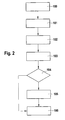
- block 100 it is determined by the vehicle control unit 15 that the separating clutch 14 is defective and only a reduced torque can be delivered from the separating clutch 14 to the drive shaft 3 for propulsion of the vehicle.
- the vehicle controller 15 checks the state of charge of the battery 12 (block 101). Exceeds the state of charge of the battery a predetermined value, a minimum torque is determined in block 102, which is taken from the reduced, delivered by the clutch torque and is used for reliable supply of the control units 15, 17, 18 of the vehicle. If the state of charge of the battery 12 falls below the predetermined value, the minimum torque continues in block 103 lowered, so that only necessary for the operational safety of the vehicle control devices such as the control unit 18 for the electronic brake continue to operate. Control units, which only ensure comfort functions of the vehicle, such as the climate control unit 17, are switched off.
- the vehicle control unit 15 checks whether the torque component of the reduced torque that exceeds and exceeds the minimum torque is sufficient for further driving of the vehicle. If this is not the case, a discharge of the battery up to a predetermined amount is made possible in block 105 in order to increase the contribution of the remaining torque component, with which the vehicle can drive to the next workshop.
- block 104 leads directly to block 106, in which the driving operation of the vehicle is detected.
- the method according to the invention can be used not only for the parallel hybrids, but for all hybrid concepts with a coupling between the internal combustion engine and the drive train.
Landscapes
- Engineering & Computer Science (AREA)
- Transportation (AREA)
- Mechanical Engineering (AREA)
- Chemical & Material Sciences (AREA)
- Combustion & Propulsion (AREA)
- Automation & Control Theory (AREA)
- Health & Medical Sciences (AREA)
- Biomedical Technology (AREA)
- General Health & Medical Sciences (AREA)
- Electric Propulsion And Braking For Vehicles (AREA)
- Hybrid Electric Vehicles (AREA)
- Control Of Vehicle Engines Or Engines For Specific Uses (AREA)
Description
- Die Erfindung betrifft ein Verfahren zum Betreiben eines Fahrzeuges mit Hybridantrieb, bei welchem ein erstes und ein zweites Antriebsaggregat gemeinsam oder allein zum Antrieb des Fahrzeuges beitragen, wobei das erste Antriebsaggregat das zweite Antriebsaggregat generatorisch zum Laden eines Energiespeichers antreibt und das erste und das zweite Antriebsaggregat durch ein, ein Moment des ersten Antriebsaggregates übertragendes Antriebsstrangelement trennbar sind sowie eine Vorrichtung zur Durchführung des Verfahrens, vgl.
EP-A1177937 ,US 2007/0216312 A ,US 2007/0219045 A . - Es werden verstärkt Fahrzeuge mit Hybridantrieben entwickelt, bei welchen verschiedene Antriebe für eine Antriebsaufgabe genutzt werden. Dabei können die einzelnen Motoren in dem Hybridantrieb unterschiedlich zusammenarbeiten. Sie wirken entweder gleichzeitig oder es wirkt nur eine Antriebseinheit auf das zu bewegende Fahrzeug.
- Bei den so genannten Parallelhybriden befindet sich ein elektrischer Antrieb auf der Welle eines Verbrennungsmotors. Um ein rein elektrisches Fahren mit stehendem Verbrennungsmotor zu gewährleisten, wird der elektrische Antrieb durch eine Trennkupplung vom Verbrennungsmotor abgekoppelt. Bei Defekten der Trennkupplung bzw. in der hydraulischen Ansteuerung der Trennkupplung kann das übertragbare Moment deutlich geringer sein als das üblicherweise maximal verfügbare Moment. Dabei wird das Moment des Verbrennungsmotors nicht nur für den Fahrzeugantrieb sondern auch für den generatorischen Betrieb des Elektromotors genutzt, welcher einen Energiespeicher auflädt.
- Im Falle eines Defektes der Trennkupplung wird der Energiespeicher weiter in der gewohnten Art aufgeladen, was dazu führen kann, dass kein Moment mehr für den Vortrieb des Fahrzeuges zur Verfügung steht. Das bedeutet, dass sich das Fahrzeug in diesem Fall nicht mehr bewegen lässt.
- Es ist bekannt, dass bei einem Fahrzeug mit Hybridantrieb die noch zurücklegbare Wegstrecke des Hybridfahrzeuges bestimmt wird, nachdem festgestellt wurde, dass ein Antriebsaggregat des Hybridantriebes nicht mehr zur Verfügung steht und mit dem verbleibenden, noch funktionstüchtigen Antriebsaggregat weitergefahren werden muss.
- Die Erfindung is durch die Ausprüche deficient. Der Vorteil der Erfindung besteht darin, dass das Fahrzeug bei einem Defekt der Trennkupplung sich noch weiter bewegen lässt, da der zum Laden des Energiespeichers genutzte Momentenanteil auf ein Minimalmoment abgesenkt wird, während der das Minimalmoment übersteigende Momentenüberschuss des sich bei einem Defekt des Antriebsstrangelementes reduzierten Momentes zur Fortbewegung des Fahrzeuges genutzt wird.
- Der Fahrer hat somit die Möglichkeit, das Fahrzeug bei einem Defekt der Trennkupplung, welcher das übertragbare Moment einschränkt, noch eine bestimmte Wegstrecke zu bewegen. Dies erlaubt ihm z.B. einen möglichen Gefahrenbereich zu verlassen, oder eine nahegelegene Werkstatt aufzusuchen.
- Um noch einen Momentenanteil für den Vortrieb des Fahrzeuges zur Verfügung zu haben, wird die Aufladung des Energiespeichers auf ein Minimum begrenzt. Dabei wird das Minimalmoment derart eingestellt, dass es dem aktuellen Leistungsbedarf der von dem Energiespeicher versorgten elektrischen Systeme des Fahrzeuges entspricht. Somit erfolgt zwar keine weitere Aufladung der Batterie, eine Entladung dieser wird aber zuverlässig verhindert. Der Ladezustand des Energiespeichers bleibt somit erhalten und es besteht noch genügend Leistung für einen Neustart des als Verbrennungsmotor ausgebildeten ersten Antriebsaggregates.
- In einer Ausgestaltung der Erfindung wird das Minimalmoment derart eingestellt, dass es dem aktuellen Leistungsbedarf der von dem Energiespeicher versorgten betriebswichtigen Systeme des Fahrzeuges entspricht, damit das Fahrzeug auch wirklich betriebssicher weiterbewegt werden kann. Zu diesen betriebswichtigen Systemen gehören u.a. elektrische Gas- und Bremssysteme, Lenksystems sowie Anzeigesysteme.
- Vorteilhafterweise wird das Minimalmoment durch Abschaltung mindestens eines, von dem Energiespeicher versorgten elektrischen Systems, reduziert. Das gezielte Abschalten betrifft besonders die Komfortsysteme im Fahrzeug, zu welchen z.B. die elektrische Scheibenheizungen, elektrische Klimaanlage und elektrische Sitzheizung gehören. Auf diese Weise steht dem Vortrieb des Fahrzeuges noch mehr Moment und somit Leistung zur Verfügung.
- Um für eine begrenzte Zeit dem Fahrzeug ein höheres Moment zur Verfügung stellen zu können, wird die Entladung des Energiespeichers bis zu einem vorgegebenen Wert zugelassen. Dadurch steht dem Antriebstrang ein höheres Moment für die Entfernung des Fahrzeuges aus einem Gefahrenbereich zur Verfügung.
- Eine weitere Möglichkeit, das Minimalmoment genau zu berechnen, besteht darin, das reduzierte, noch übertragbare Moment der Trennkupplung je zu einem bestimmten Teil auf das erste und das zweite Antriebsaggregat aufzuteilen. Damit wird sichergestellt, dass genügend Moment für den Vortrieb zur Verfügung steht.
- Bei einer anderen Weiterbildung der Erfindung weist eine Vorrichtung zum Betreiben eines Fahrzeuges mit Hybridantrieb, bei welchem ein erstes und ein zweites Antriebsaggregat gemeinsam oder allein zum Antrieb des Fahrzeuges beitragen, wobei das erste Antriebsaggregat das zweite Antriebsaggregat generatorisch zum Laden eines Energiespeichers antreibt und das erste und das zweite Antriebsaggregat durch ein, ein Moment des ersten Antriebsaggregates übertragendes Antriebsstrangelement trennbar sind, Mittel auf, welche den zum Laden des Energiespeichers genutzte Momentenanteil auf ein Minimalmoment absenken und den das Minimalmoment übersteigenden Momentenüberschuss des sich bei einem Defekt des Antriebsstrangelementes reduzierten Momentes zur Fortbewegung des Fahrzeuges nutzen. Mit dieser Vorrichtung wird ein zeitweises Fortbewegen des Fahrzeuges aus dem Gefahrenbereich oder bis zur nächsten Werkstatt gewährleistet.
- Die Erfindung lässt zahlreiche Ausführungsformen zu. Eine davon soll anhand der in der Zeichnung dargestellten Figuren näher erläutert werden.
- Es zeigt:
- Figur 1:
- Prinzipdarstellung eines Parallelhybriden
- Figur 2:
- ein Ausführungsbeispiel für das erfindungsgemäße Verfahren
- In
Figur 1 ist ein Parallelhybridantrieb dargestellt, welcher von einem Verbrennungsmotor 1 als erste Antriebseinheit und einem Elektromotor 2 als zweite Antriebseinheit gebildet ist. Der Elektromotor 2 ist dabei auf der Antriebswelle 3 des Verbrennungsmotors 1 aufgesetzt, welche mit dem Getriebe 4 verbunden ist, welches wiederum über das Differential 5 auf die Radachse 6 zum Antrieb des Rades 7 führt. Der Verbrennungsmotor 1 und der Elektromotor 2 sind über eine Trennkupplung 8, die in der Antriebswelle 3 angeordnet ist, entkoppelbar. - Der Elektromotor 2 verfügt über ein eigenes Elektromotorsteuergerät 9, welches an einen Hybrid CAN-Bus 10 angeschlossen ist, über welchen alle die Steuergeräte miteinander kommunizieren, die Einfluss auf den Hybrid spezifischen Fahrbetrieb des Fahrzeuges haben. Dazu gehören das Batteriemanagementsystem 11 der Batterie 12, ein AC-Kompressor 13 (Wechselstrom-Kompressor) und weitere nicht weiter dargestellte Steuergeräte, die u.a. das Getriebe steuern. Darüber hinaus ist eine Kupplungselektronik 14 ebenfalls mit dem Hybrid CAN-Bus 10 verbunden.
- Ein Fahrzeugsteuergerät 15 kommuniziert über den Hybrid CAN Bus 10 mit den daran angeschlossenen Steuergeräten, insbesondere dem Elektromotorsteuergerät 9 und dem Batteriemanagementsystem 11. Darüber hinaus ist es über den CAN Bus 16 mit verschiedenen Steuergeräten verbunden, von welchen nur das Klimasteuergerät 17 und das Steuergerät für die elektrische Bremse 18 dargestellt sind.
- Ein Motorsteuergerät 19 des Verbrennungsmotors 1 ist über den Hybrid CAN Bus 10 ebenfalls mit dem Fahrzeugsteuergerät 15 verbunden.
- Im Fahrzeugsteuergerät 15 wird das Drehmoment des Vortriebs für das Hybridfahrzeug gesteuert. Zu diesem Zweck wertet das Fahrzeugsteuergerät 15 u.a. die von der Kupplungselektronik 14 gelieferten Daten aus. Dabei wird das für den Vortrieb relevante Drehmoment sowohl vom Verbrennungsmotor 1 als auch vom Elektromotor 2 aufgebracht. Das Fahrzeugsteuergerät 15 arbeitet als Koordinierungseinheit und koordiniert die Beiträge, welche vom Verbrennungsmotor 1 und vom Elektromotor 2 zum Drehmoment geleistet werden.
- Von dem Batteriemanagementsystem 11 wird dem Fahrzeugsteuergerät 15 der jeweils aktuelle Ladezustand der Batterie 12 gemeldet. Dabei wird die Batterie 12 aufgeladen, wenn der Elektromotor 2 im generatorischen Betrieb arbeitet, d.h. der Verbrennungsmotor 1 treibt den Elektromotor 2 mechanisch an, welcher darauf hin elektrische Energie produziert, die in der Batterie 12 gespeichert wird. Mit dieser gespeicherten Energie werden einmal die Steuergeräte 15, 17, 18 des Hybridfahrzeuges mit elektrischer Energie versorgt. Andererseits dient diese Energie auch dazu, den Elektromotor 2 anzutreiben, wenn dieser einen Beitrag zum Vortrieb des Fahrzeuges leistet.
- In
Figur 2 soll nun der Fall betrachtet werden, dass die Trennkupplung 8 defekt ist und nicht mehr das maximale Moment, welches vom Verbrennungsmotor 1 aufgebracht wird, auf die Antriebswelle 3 übetragen kann. In diesem Fall muss gewährleistet werden, dass das Fahrzeug fahrbereit bleibt, um sich aus einer Gefahrensituation zu bewegen oder zumindest die nächste Werkstatt zu erreichen. - In Block 100 wird durch das Fahrzeugsteuergerät 15 festgestellt, dass die Trennkupplung 14 defekt ist und nur noch ein reduziertes Moment von der Trennkupplung 14 auf die Antriebswelle 3 zum Vortrieb des Fahrzeuges abgegeben werden kann. Daraufhin prüft das Fahrzeugsteuergerät 15 den Ladezustand der Batterie 12 (Block 101). Überschreitet der Ladezustand der Batterie einen vorgegebenen Wert, wird im Block 102 ein Mindestmoment festgelegt, welches dem reduzierten, von der Trennkupplung gelieferten Moment entnommen wird und zur zuverlässigen Versorgung der Steuergeräte 15, 17, 18 des Fahrzeuges dient. Unterschreitet der Ladezustand der Batterie 12 den vorgegebenen Wert, wird im Block 103 das Mindestmoment weiter abgesenkt, so dass nur die für die Betriebssicherheit des Fahrzeuges notwendigen Steuergeräte wie beispielsweise das Steuergerät 18 für die elektronische Bremse weiter betrieben werden. Steuergeräte, welche nur Komfortfunktionen des Fahrzeuges absichern, wie das Klimasteuergerät 17, werden abgeschaltet.
- Im Block 104 prüft das Fahrzeugsteuergerät 15, ob der über das Mindestmoment hinausgehende und verbleibende Momentenanteil des reduzierten Momentes für eine Weiterfahrt des Fahrzeuges ausreicht. Ist dies nicht der Fall, wird im Block 105 ein Entladen der Batterie bis zu einem vorgegebenen Betrag ermöglicht, um den Beitrag des verbleibenden Momentenanteiles zu erhöhen, womit das Fahrzeug bis zur nächsten Werkstatt fahren kann.
- Reicht das reduzierte Moment zur Weiterfahrt des Fahrzeuges aus, wird vom Block 104 direkt zum Block 106 über gegangen, in welchem der Fahrbetrieb des Fahrzeuges detektiert wird.
- Das erfindungsgemäße Verfahren ist nicht nur für die Parallelhybride einsetzbar, sondern für alle hybride Konzepte mit einer Kupplung zwischen dem Verbrennungsmotor und dem Antriebsstrang.
Claims (8)
- Verfahren zum Betreiben eines Fahrzeuges mit Hybridantrieb, bei welchem ein erstes (1) und ein zweites Antriebsaggregat (2) gemeinsam oder allein zum Antrieb des Fahrzeuges beitragen, wobei das erste Antriebsaggregat (1) das zweite Antriebsaggregat (2) generatorisch zum Laden eines Energiespeichers (12) antreibt, wobei das erste (1) und das zweite Antriebsaggregat (2) durch ein, ein Moment des ersten Antriebsaggregates übertragendes Antriebsstrangelement (8) trennbar sind, dadurch gekennzeichnet, dass der zum Laden des Energiespeichers (12) genutzte Momentenanteil auf ein Minimalmoment abgesenkt wird, während der, das Minimalmoment übersteigende Momentenüberschuss des sich bei einem Defekt des Antriebsstrangelementes (8) reduzierten Momentes zur Fortbewegung des Fahrzeuges genutzt wird.
- Verfahren nach Anspruch 1 dadurch gekennzeichnet, dass das Minimalmoment derart eingestellt wird, dass es dem aktuellen Leistungsbedarf der von dem Energiespeicher (12) versorgten elektrischen Systeme (15, 17, 18) des Fahrzeuges entspricht.
- Verfahren nach Anspruch 2 dadurch gekennzeichnet, dass das Minimalmoment derart eingestellt wird, dass es dem aktuellen Leistungsbedarf der von dem Energiespeicher (12) versorgten betriebswichtigen Systeme (18) des Fahrzeuges entspricht.
- Verfahren nach Anspruch 2 dadurch gekennzeichnet, dass das Minimalmoment durch Abschaltung mindestens eines, von dem Energiespeicher (12) versorgten elektrischen Systems (17) reduziert wird.
- Verfahren nach einem der vorhergehenden Ansprüche dadurch gekennzeichnet, dass zum Antrieb des Fahrzeuges soviel Energie aus dem Energiespeicher (12) entnommen wird, dass der Energiespeicher (12) bis auf einen vorgegebenen Wert entladen wird.
- Vorrichtung zum Betreiben eines Fahrzeuges mit Hybridantrieb, bei welchem ein erstes (1) und ein zweites Antriebsaggregat (2) gemeinsam oder allein zum Antrieb des Fahrzeuges beitragen, wobei das erste Antriebsaggregat (1) das zweite Antriebsaggregat (2) generatorisch zum Laden eines Energiespeichers (12) antreibt und das erste (1) und das zweite Antriebsaggregat (2) durch ein, ein Moment des ersten Antriebsaggregates (1) übertragendes Antriebsstrangelement (8) trennbar sind, dadurch gekennzeichnet, dass Mittel (15) vorhanden sind, welche den zum Laden des Energiespeichers (12) genutzten Momentenanteil auf ein Minimalmoment absenken und den das Minimalmoment übersteigenden Momentenüberschuss des sich bei einem Defekt des Antriebsstrangelementes (8) reduzierten Momentes zur Fortbewegung des Fahrzeuges nutzen.
- Vorrichtung nach Anspruch 6 dadurch gekennzeichnet, dass das erste Antriebsaggregat (1) als Brennkraftmaschine und das zweite Antriebaggregat (2) als Elektromotor ausgebildet sind.
- Vorrichtung nach Anspruch 6 dadurch gekennzeichnet, dass das Antriebsstrangelement (8) eine Trennkupplung zum Abkoppeln des ersten Antriebaggregates (1) vom zweiten Antriebsaggregat (2) ist.
Applications Claiming Priority (2)
| Application Number | Priority Date | Filing Date | Title |
|---|---|---|---|
| DE102008002691A DE102008002691A1 (de) | 2008-06-26 | 2008-06-26 | Verfahren und Vorrichtung zum Betreiben eines Fahrzeuges mit Hybridantrieb |
| PCT/EP2009/053436 WO2009156192A1 (de) | 2008-06-26 | 2009-03-24 | Verfahren und vorrichtung zum betreiben eines fahrzeuges mit hybridantrieb |
Publications (2)
| Publication Number | Publication Date |
|---|---|
| EP2303662A1 EP2303662A1 (de) | 2011-04-06 |
| EP2303662B1 true EP2303662B1 (de) | 2011-11-09 |
Family
ID=40724885
Family Applications (1)
| Application Number | Title | Priority Date | Filing Date |
|---|---|---|---|
| EP09769041A Not-in-force EP2303662B1 (de) | 2008-06-26 | 2009-03-24 | Verfahren und vorrichtung zum betreiben eines fahrzeuges mit hybridantrieb |
Country Status (8)
| Country | Link |
|---|---|
| US (1) | US8712657B2 (de) |
| EP (1) | EP2303662B1 (de) |
| JP (1) | JP5101733B2 (de) |
| KR (1) | KR101510501B1 (de) |
| CN (1) | CN102083664B (de) |
| AT (1) | ATE532686T1 (de) |
| DE (1) | DE102008002691A1 (de) |
| WO (1) | WO2009156192A1 (de) |
Families Citing this family (5)
| Publication number | Priority date | Publication date | Assignee | Title |
|---|---|---|---|---|
| DE102008044016B4 (de) * | 2008-11-24 | 2025-07-31 | Robert Bosch Gmbh | Verfahren zum Erfassen eines sich einstellenden Drehmomentes für einen Hybridantrieb |
| JP2011230706A (ja) * | 2010-04-28 | 2011-11-17 | Toyota Motor Corp | 車両の制御装置 |
| DE102010036266A1 (de) * | 2010-09-03 | 2012-03-08 | Alexander Koslow | Steuerung eines Kraftfahrzeuges für eine ökologische Betriebsweise (City-Fahrzyklus) |
| US9566985B2 (en) * | 2011-02-08 | 2017-02-14 | GM Global Technology Operations LLC | Method and apparatus for monitoring a resolver in a torque machine |
| JP6318909B2 (ja) | 2014-06-25 | 2018-05-09 | 三菱自動車工業株式会社 | ハイブリッド車両の制御装置 |
Family Cites Families (22)
| Publication number | Priority date | Publication date | Assignee | Title |
|---|---|---|---|---|
| US4838125A (en) * | 1986-02-07 | 1989-06-13 | Toyota Jidosha Kabushiki Kaisha | System for shift control in automatic transmission |
| US6007443A (en) * | 1996-02-16 | 1999-12-28 | Nippon Soken, Inc. | Hybrid vehicle |
| JP3749302B2 (ja) * | 1996-04-11 | 2006-02-22 | トヨタ自動車株式会社 | ハイブリッド車両の駆動制御装置 |
| JPH11270668A (ja) * | 1998-03-20 | 1999-10-05 | Nissan Motor Co Ltd | ハイブリッド車両の駆動制御装置 |
| JP3536658B2 (ja) * | 1998-03-31 | 2004-06-14 | 日産自動車株式会社 | ハイブリッド車両の駆動制御装置 |
| JP3172490B2 (ja) * | 1998-05-18 | 2001-06-04 | 株式会社日立製作所 | ハイブリッド車 |
| JP3668838B2 (ja) * | 2000-08-01 | 2005-07-06 | トヨタ自動車株式会社 | 車両の制御装置 |
| JP2002051407A (ja) | 2000-08-03 | 2002-02-15 | Toyota Motor Corp | パワートレーンの制御装置 |
| JP2004056922A (ja) * | 2002-07-19 | 2004-02-19 | Toyota Motor Corp | 動力出力装置およびこれを備える自動車 |
| JP2005080437A (ja) * | 2003-09-01 | 2005-03-24 | Honda Motor Co Ltd | 車両用モータ駆動装置 |
| JP2006306327A (ja) * | 2005-04-28 | 2006-11-09 | Nissan Motor Co Ltd | 車両用ハイブリッド駆動装置 |
| DE102005039461A1 (de) * | 2005-08-20 | 2007-03-15 | Daimlerchrysler Ag | Hybrider Antriebsstrang eines Kraftfahrzeugs und Verfahren zum Betrieb eines hybriden Antriebsstrangs |
| DE102007011410A1 (de) * | 2006-03-14 | 2007-11-08 | Mitsubishi Fuso Truck and Bus Corp., Kawasaki | Steuergerät für ein elektrisches Hybridfahrzeug |
| JP2007245805A (ja) * | 2006-03-14 | 2007-09-27 | Mitsubishi Fuso Truck & Bus Corp | ハイブリッド電気自動車の制御装置 |
| JP2007246011A (ja) | 2006-03-17 | 2007-09-27 | Mitsubishi Fuso Truck & Bus Corp | ハイブリッド電気自動車の制御装置 |
| JP2007261415A (ja) * | 2006-03-28 | 2007-10-11 | Mitsubishi Fuso Truck & Bus Corp | ハイブリッド自動車の制御装置 |
| US7867135B2 (en) * | 2007-09-26 | 2011-01-11 | GM Global Technology Operations LLC | Electro-mechanical transmission control system |
| DE102007050301B4 (de) * | 2007-10-22 | 2021-10-21 | Robert Bosch Gmbh | Verfahren und Vorrichtung zum Erkennen einer Fehlfunktion einer Kupplung |
| DE102008008207A1 (de) * | 2008-02-07 | 2009-08-13 | Robert Bosch Gmbh | Verfahren zum ausfallsicheren Betreiben eines Hybridfahrzeugs zum kontrollierten Hervorrufen von einer einen Notlauf des Fahrzeugs ermöglichenden Ersatzmaßnahme und Vorrichtung zum Durchführen dieses Verfahrens |
| WO2009152793A1 (de) * | 2008-06-19 | 2009-12-23 | Luk Lamellen Und Kupplungsbau Beteiligungs Kg | Schaltbare kupplungseinrichtung, insbesondere reibschlüssige nasskupplung, antriebsstrang für ein hybridsystem und verfahren zum betreiben eines derartigen antriebsstranges und fahrzeug mit einem derartigen antriebsstrang |
| DE102008040400A1 (de) * | 2008-07-15 | 2010-01-21 | Robert Bosch Gmbh | Verfahren und Vorrichtung zum Betrieb eines Hybridantriebs eines Fahrzeuges |
| DE102009026702B4 (de) * | 2009-06-04 | 2025-12-31 | Zf Friedrichshafen Ag | Verfahren und Vorrichtung zur Steuerung eines Parallelhybridantriebsstranges eines Fahrzeugs |
-
2008
- 2008-06-26 DE DE102008002691A patent/DE102008002691A1/de not_active Withdrawn
-
2009
- 2009-03-24 KR KR1020117001838A patent/KR101510501B1/ko not_active Expired - Fee Related
- 2009-03-24 JP JP2011515252A patent/JP5101733B2/ja not_active Expired - Fee Related
- 2009-03-24 US US13/000,837 patent/US8712657B2/en not_active Expired - Fee Related
- 2009-03-24 EP EP09769041A patent/EP2303662B1/de not_active Not-in-force
- 2009-03-24 CN CN2009801241303A patent/CN102083664B/zh not_active Expired - Fee Related
- 2009-03-24 AT AT09769041T patent/ATE532686T1/de active
- 2009-03-24 WO PCT/EP2009/053436 patent/WO2009156192A1/de not_active Ceased
Also Published As
| Publication number | Publication date |
|---|---|
| DE102008002691A1 (de) | 2009-12-31 |
| JP2011525872A (ja) | 2011-09-29 |
| US20110180337A1 (en) | 2011-07-28 |
| US8712657B2 (en) | 2014-04-29 |
| CN102083664B (zh) | 2013-11-06 |
| WO2009156192A1 (de) | 2009-12-30 |
| JP5101733B2 (ja) | 2012-12-19 |
| EP2303662A1 (de) | 2011-04-06 |
| CN102083664A (zh) | 2011-06-01 |
| KR101510501B1 (ko) | 2015-04-08 |
| KR20110050627A (ko) | 2011-05-16 |
| ATE532686T1 (de) | 2011-11-15 |
Similar Documents
| Publication | Publication Date | Title |
|---|---|---|
| EP2477839B1 (de) | Verfahren und vorrichtung zum betreiben eines hybridfahrzeuges beim defekt eines energiesystems | |
| DE102016108918B4 (de) | Fahrzeugsystem und Verfahren zum Aktivieren von Warnleuchten bei Batterieabklemmereignissen | |
| DE102008030581A1 (de) | Triebstrang für ein Kraftfahrzeug und Verfahren zum Betreiben eines Triebstrangs eines Kraftfahrzeuges | |
| EP2842814A1 (de) | Fahrzeuganhänger | |
| EP3515741B1 (de) | Verfahren zum betreiben eines hybridfahrzeugs | |
| DE102007038585A1 (de) | Verfahren zur Lastpunktverschiebung im Hybridbetrieb bei einem parallelen Hybridfahrzeug | |
| DE102014012090A1 (de) | Hybridfahrzeug mit einer externen elektrischen Schnittstelle | |
| DE102008002666A1 (de) | Verfahren und Vorrichtung zum Starten eines Verbrennungsmotors eines Hybridantriebsstranges | |
| DE102013218634A1 (de) | Steuerstrategie für eine elektrische maschine eines fahrzeugs | |
| DE102018210911A1 (de) | Verfahren zum Betreiben eines Antriebssystems für eine Arbeitsmaschine, Antriebssystem und Arbeitsmaschine | |
| EP2303662B1 (de) | Verfahren und vorrichtung zum betreiben eines fahrzeuges mit hybridantrieb | |
| DE102011104443A1 (de) | Verfahren zum Betrieb eines Hybridfahrzeugs | |
| WO2006128599A1 (de) | Energiespeichereinrichtung | |
| WO2009021909A1 (de) | Verfahren zum betrieb eines gleichstrom-spannungswandlers in einem hybridfahrzeug | |
| DE102007011257A1 (de) | Hybridantrieb, Verfahren zum Steuern eines Druckluftkompressors und Kraftfahrzeug mit einem Hybridantrieb | |
| DE102011079456A1 (de) | Verfahren und Vorrichtung zum Schutz eines Akkumulators eines hybridelektrischen Fahrzeugs | |
| DE102011087122A1 (de) | Verfahren und Vorrichtung zum Steuern des Antriebsstrangs in einem Elektrofahrzeug | |
| DE112016005158T5 (de) | Verfahren zur Steuerung eines n-achsigen Anhängers einer Zugmaschine und Vorrichtung zu seiner Durchführung | |
| DE102012208462B4 (de) | Vorrichtung zum Betreiben eines Antriebsstrangs | |
| DE102012022460A1 (de) | Notstartverfahren für Verbrennungskraftmaschinen in Fahrzeugen | |
| DE102013002653B4 (de) | Verfahren zur Aktivierung der Klimatisierung eines Fahrzeugs und Klimaanlage zur Durchführung des Verfahrens | |
| EP3962770A1 (de) | Verfahren zum aufladen einer hochvolt-batterie eines elektroantriebs eines fahrzeugs, sowie energieübertragungssystem für ein fahrzeug | |
| DE102005025617B4 (de) | Steuereinrichtung für ein Antriebssystem in einem Kraftfahrzeug mit einem variablen Allradantrieb | |
| DE102007055218A1 (de) | Energieversorgungssystem und -verfahren für Fahrzeugsubsysteme | |
| DE102019217707B4 (de) | Verfahren und Steuereinrichtung zur Reichweitenoptimierung eines Gespanns bestehend aus einem antreibbaren Zugfahrzeug und einem antreibbaren Anhänger |
Legal Events
| Date | Code | Title | Description |
|---|---|---|---|
| PUAI | Public reference made under article 153(3) epc to a published international application that has entered the european phase |
Free format text: ORIGINAL CODE: 0009012 |
|
| 17P | Request for examination filed |
Effective date: 20110126 |
|
| AK | Designated contracting states |
Kind code of ref document: A1 Designated state(s): AT BE BG CH CY CZ DE DK EE ES FI FR GB GR HR HU IE IS IT LI LT LU LV MC MK MT NL NO PL PT RO SE SI SK TR |
|
| AX | Request for extension of the european patent |
Extension state: AL BA RS |
|
| GRAP | Despatch of communication of intention to grant a patent |
Free format text: ORIGINAL CODE: EPIDOSNIGR1 |
|
| DAX | Request for extension of the european patent (deleted) | ||
| GRAS | Grant fee paid |
Free format text: ORIGINAL CODE: EPIDOSNIGR3 |
|
| GRAA | (expected) grant |
Free format text: ORIGINAL CODE: 0009210 |
|
| AK | Designated contracting states |
Kind code of ref document: B1 Designated state(s): AT BE BG CH CY CZ DE DK EE ES FI FR GB GR HR HU IE IS IT LI LT LU LV MC MK MT NL NO PL PT RO SE SI SK TR |
|
| REG | Reference to a national code |
Ref country code: GB Ref legal event code: FG4D Free format text: NOT ENGLISH |
|
| REG | Reference to a national code |
Ref country code: CH Ref legal event code: EP |
|
| REG | Reference to a national code |
Ref country code: IE Ref legal event code: FG4D Free format text: LANGUAGE OF EP DOCUMENT: GERMAN |
|
| REG | Reference to a national code |
Ref country code: DE Ref legal event code: R096 Ref document number: 502009001909 Country of ref document: DE Effective date: 20111229 |
|
| REG | Reference to a national code |
Ref country code: DE Ref legal event code: R096 Ref document number: 502009001909 Country of ref document: DE Effective date: 20111229 |
|
| REG | Reference to a national code |
Ref country code: NL Ref legal event code: VDEP Effective date: 20111109 |
|
| LTIE | Lt: invalidation of european patent or patent extension |
Effective date: 20111109 |
|
| PG25 | Lapsed in a contracting state [announced via postgrant information from national office to epo] |
Ref country code: NO Free format text: LAPSE BECAUSE OF FAILURE TO SUBMIT A TRANSLATION OF THE DESCRIPTION OR TO PAY THE FEE WITHIN THE PRESCRIBED TIME-LIMIT Effective date: 20120209 Ref country code: IS Free format text: LAPSE BECAUSE OF FAILURE TO SUBMIT A TRANSLATION OF THE DESCRIPTION OR TO PAY THE FEE WITHIN THE PRESCRIBED TIME-LIMIT Effective date: 20120309 Ref country code: LT Free format text: LAPSE BECAUSE OF FAILURE TO SUBMIT A TRANSLATION OF THE DESCRIPTION OR TO PAY THE FEE WITHIN THE PRESCRIBED TIME-LIMIT Effective date: 20111109 |
|
| PG25 | Lapsed in a contracting state [announced via postgrant information from national office to epo] |
Ref country code: SE Free format text: LAPSE BECAUSE OF FAILURE TO SUBMIT A TRANSLATION OF THE DESCRIPTION OR TO PAY THE FEE WITHIN THE PRESCRIBED TIME-LIMIT Effective date: 20111109 Ref country code: PT Free format text: LAPSE BECAUSE OF FAILURE TO SUBMIT A TRANSLATION OF THE DESCRIPTION OR TO PAY THE FEE WITHIN THE PRESCRIBED TIME-LIMIT Effective date: 20120309 Ref country code: PL Free format text: LAPSE BECAUSE OF FAILURE TO SUBMIT A TRANSLATION OF THE DESCRIPTION OR TO PAY THE FEE WITHIN THE PRESCRIBED TIME-LIMIT Effective date: 20111109 Ref country code: NL Free format text: LAPSE BECAUSE OF FAILURE TO SUBMIT A TRANSLATION OF THE DESCRIPTION OR TO PAY THE FEE WITHIN THE PRESCRIBED TIME-LIMIT Effective date: 20111109 Ref country code: HR Free format text: LAPSE BECAUSE OF FAILURE TO SUBMIT A TRANSLATION OF THE DESCRIPTION OR TO PAY THE FEE WITHIN THE PRESCRIBED TIME-LIMIT Effective date: 20111109 Ref country code: LV Free format text: LAPSE BECAUSE OF FAILURE TO SUBMIT A TRANSLATION OF THE DESCRIPTION OR TO PAY THE FEE WITHIN THE PRESCRIBED TIME-LIMIT Effective date: 20111109 Ref country code: SI Free format text: LAPSE BECAUSE OF FAILURE TO SUBMIT A TRANSLATION OF THE DESCRIPTION OR TO PAY THE FEE WITHIN THE PRESCRIBED TIME-LIMIT Effective date: 20111109 Ref country code: GR Free format text: LAPSE BECAUSE OF FAILURE TO SUBMIT A TRANSLATION OF THE DESCRIPTION OR TO PAY THE FEE WITHIN THE PRESCRIBED TIME-LIMIT Effective date: 20120210 |
|
| REG | Reference to a national code |
Ref country code: IE Ref legal event code: FD4D |
|
| PG25 | Lapsed in a contracting state [announced via postgrant information from national office to epo] |
Ref country code: CY Free format text: LAPSE BECAUSE OF FAILURE TO SUBMIT A TRANSLATION OF THE DESCRIPTION OR TO PAY THE FEE WITHIN THE PRESCRIBED TIME-LIMIT Effective date: 20111109 |
|
| PG25 | Lapsed in a contracting state [announced via postgrant information from national office to epo] |
Ref country code: DK Free format text: LAPSE BECAUSE OF FAILURE TO SUBMIT A TRANSLATION OF THE DESCRIPTION OR TO PAY THE FEE WITHIN THE PRESCRIBED TIME-LIMIT Effective date: 20111109 Ref country code: EE Free format text: LAPSE BECAUSE OF FAILURE TO SUBMIT A TRANSLATION OF THE DESCRIPTION OR TO PAY THE FEE WITHIN THE PRESCRIBED TIME-LIMIT Effective date: 20111109 Ref country code: IE Free format text: LAPSE BECAUSE OF FAILURE TO SUBMIT A TRANSLATION OF THE DESCRIPTION OR TO PAY THE FEE WITHIN THE PRESCRIBED TIME-LIMIT Effective date: 20111109 Ref country code: SK Free format text: LAPSE BECAUSE OF FAILURE TO SUBMIT A TRANSLATION OF THE DESCRIPTION OR TO PAY THE FEE WITHIN THE PRESCRIBED TIME-LIMIT Effective date: 20111109 Ref country code: CZ Free format text: LAPSE BECAUSE OF FAILURE TO SUBMIT A TRANSLATION OF THE DESCRIPTION OR TO PAY THE FEE WITHIN THE PRESCRIBED TIME-LIMIT Effective date: 20111109 Ref country code: BG Free format text: LAPSE BECAUSE OF FAILURE TO SUBMIT A TRANSLATION OF THE DESCRIPTION OR TO PAY THE FEE WITHIN THE PRESCRIBED TIME-LIMIT Effective date: 20120209 |
|
| PG25 | Lapsed in a contracting state [announced via postgrant information from national office to epo] |
Ref country code: RO Free format text: LAPSE BECAUSE OF FAILURE TO SUBMIT A TRANSLATION OF THE DESCRIPTION OR TO PAY THE FEE WITHIN THE PRESCRIBED TIME-LIMIT Effective date: 20111109 |
|
| PLBE | No opposition filed within time limit |
Free format text: ORIGINAL CODE: 0009261 |
|
| STAA | Information on the status of an ep patent application or granted ep patent |
Free format text: STATUS: NO OPPOSITION FILED WITHIN TIME LIMIT |
|
| BERE | Be: lapsed |
Owner name: ROBERT BOSCH G.M.B.H. Effective date: 20120331 |
|
| 26N | No opposition filed |
Effective date: 20120810 |
|
| PG25 | Lapsed in a contracting state [announced via postgrant information from national office to epo] |
Ref country code: MC Free format text: LAPSE BECAUSE OF NON-PAYMENT OF DUE FEES Effective date: 20120331 |
|
| REG | Reference to a national code |
Ref country code: DE Ref legal event code: R097 Ref document number: 502009001909 Country of ref document: DE Effective date: 20120810 |
|
| PG25 | Lapsed in a contracting state [announced via postgrant information from national office to epo] |
Ref country code: BE Free format text: LAPSE BECAUSE OF NON-PAYMENT OF DUE FEES Effective date: 20120331 |
|
| PG25 | Lapsed in a contracting state [announced via postgrant information from national office to epo] |
Ref country code: MK Free format text: LAPSE BECAUSE OF FAILURE TO SUBMIT A TRANSLATION OF THE DESCRIPTION OR TO PAY THE FEE WITHIN THE PRESCRIBED TIME-LIMIT Effective date: 20111109 |
|
| PG25 | Lapsed in a contracting state [announced via postgrant information from national office to epo] |
Ref country code: ES Free format text: LAPSE BECAUSE OF FAILURE TO SUBMIT A TRANSLATION OF THE DESCRIPTION OR TO PAY THE FEE WITHIN THE PRESCRIBED TIME-LIMIT Effective date: 20120220 |
|
| PG25 | Lapsed in a contracting state [announced via postgrant information from national office to epo] |
Ref country code: FI Free format text: LAPSE BECAUSE OF FAILURE TO SUBMIT A TRANSLATION OF THE DESCRIPTION OR TO PAY THE FEE WITHIN THE PRESCRIBED TIME-LIMIT Effective date: 20111109 |
|
| PG25 | Lapsed in a contracting state [announced via postgrant information from national office to epo] |
Ref country code: MT Free format text: LAPSE BECAUSE OF FAILURE TO SUBMIT A TRANSLATION OF THE DESCRIPTION OR TO PAY THE FEE WITHIN THE PRESCRIBED TIME-LIMIT Effective date: 20111109 |
|
| REG | Reference to a national code |
Ref country code: CH Ref legal event code: PL |
|
| PG25 | Lapsed in a contracting state [announced via postgrant information from national office to epo] |
Ref country code: LI Free format text: LAPSE BECAUSE OF NON-PAYMENT OF DUE FEES Effective date: 20130331 Ref country code: CH Free format text: LAPSE BECAUSE OF NON-PAYMENT OF DUE FEES Effective date: 20130331 |
|
| PG25 | Lapsed in a contracting state [announced via postgrant information from national office to epo] |
Ref country code: TR Free format text: LAPSE BECAUSE OF FAILURE TO SUBMIT A TRANSLATION OF THE DESCRIPTION OR TO PAY THE FEE WITHIN THE PRESCRIBED TIME-LIMIT Effective date: 20111109 |
|
| PG25 | Lapsed in a contracting state [announced via postgrant information from national office to epo] |
Ref country code: LU Free format text: LAPSE BECAUSE OF NON-PAYMENT OF DUE FEES Effective date: 20120324 |
|
| PG25 | Lapsed in a contracting state [announced via postgrant information from national office to epo] |
Ref country code: HU Free format text: LAPSE BECAUSE OF FAILURE TO SUBMIT A TRANSLATION OF THE DESCRIPTION OR TO PAY THE FEE WITHIN THE PRESCRIBED TIME-LIMIT Effective date: 20090324 |
|
| REG | Reference to a national code |
Ref country code: AT Ref legal event code: MM01 Ref document number: 532686 Country of ref document: AT Kind code of ref document: T Effective date: 20140324 |
|
| PG25 | Lapsed in a contracting state [announced via postgrant information from national office to epo] |
Ref country code: AT Free format text: LAPSE BECAUSE OF NON-PAYMENT OF DUE FEES Effective date: 20140324 |
|
| REG | Reference to a national code |
Ref country code: FR Ref legal event code: PLFP Year of fee payment: 8 |
|
| REG | Reference to a national code |
Ref country code: FR Ref legal event code: PLFP Year of fee payment: 9 |
|
| REG | Reference to a national code |
Ref country code: FR Ref legal event code: PLFP Year of fee payment: 10 |
|
| PGFP | Annual fee paid to national office [announced via postgrant information from national office to epo] |
Ref country code: IT Payment date: 20200325 Year of fee payment: 12 Ref country code: GB Payment date: 20200325 Year of fee payment: 12 |
|
| PGFP | Annual fee paid to national office [announced via postgrant information from national office to epo] |
Ref country code: FR Payment date: 20200325 Year of fee payment: 12 |
|
| PGFP | Annual fee paid to national office [announced via postgrant information from national office to epo] |
Ref country code: DE Payment date: 20210521 Year of fee payment: 13 |
|
| GBPC | Gb: european patent ceased through non-payment of renewal fee |
Effective date: 20210324 |
|
| PG25 | Lapsed in a contracting state [announced via postgrant information from national office to epo] |
Ref country code: GB Free format text: LAPSE BECAUSE OF NON-PAYMENT OF DUE FEES Effective date: 20210324 Ref country code: FR Free format text: LAPSE BECAUSE OF NON-PAYMENT OF DUE FEES Effective date: 20210331 |
|
| PG25 | Lapsed in a contracting state [announced via postgrant information from national office to epo] |
Ref country code: IT Free format text: LAPSE BECAUSE OF NON-PAYMENT OF DUE FEES Effective date: 20210324 |
|
| REG | Reference to a national code |
Ref country code: DE Ref legal event code: R119 Ref document number: 502009001909 Country of ref document: DE |
|
| PG25 | Lapsed in a contracting state [announced via postgrant information from national office to epo] |
Ref country code: DE Free format text: LAPSE BECAUSE OF NON-PAYMENT OF DUE FEES Effective date: 20221001 |