EP2303696B1 - Avionikgerät mit einem system zur abführung eines durch eine gewitterentladung auf ein luftfahrzeug erzeugten blitzstroms - Google Patents
Avionikgerät mit einem system zur abführung eines durch eine gewitterentladung auf ein luftfahrzeug erzeugten blitzstroms Download PDFInfo
- Publication number
- EP2303696B1 EP2303696B1 EP09766014A EP09766014A EP2303696B1 EP 2303696 B1 EP2303696 B1 EP 2303696B1 EP 09766014 A EP09766014 A EP 09766014A EP 09766014 A EP09766014 A EP 09766014A EP 2303696 B1 EP2303696 B1 EP 2303696B1
- Authority
- EP
- European Patent Office
- Prior art keywords
- plate
- metal
- aircraft
- skin
- expanded metal
- Prior art date
- Legal status (The legal status is an assumption and is not a legal conclusion. Google has not performed a legal analysis and makes no representation as to the accuracy of the status listed.)
- Not-in-force
Links
Images


Classifications
-
- B—PERFORMING OPERATIONS; TRANSPORTING
- B64—AIRCRAFT; AVIATION; COSMONAUTICS
- B64D—EQUIPMENT FOR FITTING IN OR TO AIRCRAFT; FLIGHT SUITS; PARACHUTES; ARRANGEMENT OR MOUNTING OF POWER PLANTS OR PROPULSION TRANSMISSIONS IN AIRCRAFT
- B64D45/00—Aircraft indicators or protectors not otherwise provided for
- B64D45/02—Lightning protectors; Static dischargers
Definitions
- the invention relates to avionic equipment comprising a system for draining a lightning current produced by a storm discharge on an aircraft made of composite material.
- the invention also relates to a method of installing this drainage system.
- the invention has applications in the field of aeronautics and, in particular, in the field of protection of aircraft and equipment installed on the skin of the aircraft.
- the structure of an aircraft is made from metal panels mounted and fixed around an internal structure also metal. These metal panels are assembled by fasteners also metal and form, once assembled, the outer skin of the aircraft, also called skin plane.
- avionic equipment also called electronic equipment, such as airspeed sensors, icing condition detectors, radio antennas, navigation antennas, traffic lights, external lamps, etc. are generally installed.
- electronic equipment such as airspeed sensors, icing condition detectors, radio antennas, navigation antennas, traffic lights, external lamps, etc.
- the antennas installed on the outer skin of the aircraft contribute to the operation of radio frequency systems and navigation systems of the aircraft
- the icing condition detectors detect the climatic conditions favoring the creation of frost to inform the aircraft.
- the airspeed sensors static pressure sockets, Pitot probes, etc.
- parameters pressure, temperature, angle of incidence, etc.
- This equipment must be installed outside the aircraft. They are mounted on a metal support, called a reinforcement plate.
- the probability of an aircraft taking lightning in flight is equal to 1 per 1000 flying hours, in the most blasted areas of the world. It is therefore understandable that in order to protect the aircraft as well as the personnel and the passengers on board the aircraft, it is important to protect the entire aircraft and the avionics equipment, lightning currents that could damage it. .
- the metal structure In conventional aircraft, that is to say with a metallic structure, the metal structure has the advantage of achieving a Faraday cage function when the aircraft takes the lightning in flight. It is known, in fact, that a Faraday cage is an enclosure impervious to electric fields that protects the interior of the enclosure from electrical nuisances. It is thus clear that when the structure of the aircraft is metallic and the avionics equipment installed outside this structure are also metallic and fixed to the structure by means of metal fasteners, then the structure of the aircraft constitutes a cage from Faraday. In this type of aircraft with a metallic structure, the outer skin, itself, serves to drain lightning currents.
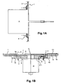
- FIG. 1A and 1B an example of avionics equipment installed on the outer skin of an aircraft with a metal structure.
- This avionic equipment is, for example, a probe 2 mounted with an aerodynamic plate 7 intended to close the orifice 6 and to ensure continuity of the profile of the aircraft.
- the probe 2 is fixed on the metal skin 1 of the aircraft by means of floating rivet nuts 4 and reinforcing plates 3 and 8.
- the reinforcing plates there is a first metal plate 8, called intermediate plate , and a second metal plate 3, called reinforcement or doubling. More specifically, the probe 2 is fixed on the intermediate plate 8, whose role is to ensure a dismountability of the probe 2 from outside the aircraft.
- the intermediate plate 8 is itself fixed on the doubler 3, the role of which is to reinforce the structural opening 6 through which the probe 2 passes.
- the doubler is placed under the outer skin 1. It has a stepped shape.
- the intermediate plate 8 has a complementary shape of the doubler 3. It is nested between the doubler 3, the probe 2 and the aerodynamic plate 7.
- the probe 2 is held on the intermediate plate 8 by metal screws 5.
- the aerodynamic plate 7 is fixed by metal screws 9 on the intermediate plate 8.
- the doubler 3 is riveted to the metal skin 1 of the aircraft.
- the doubler 3 is also attached to the metal skin 1 by screws 10.
- the probe is "metallized" to the skin of the aircraft, that is to say that it forms, with the to double, the skin, the metal plates, the metal screws and the floating nuts, a continuous metallic assembly, thus electrically conductive.
- the lightning current is thus drained by the metal parts located near the probe to the outer metallic skin of the aircraft, so that very little of the electric current is injected inside the aircraft.
- the steel-structured aircraft have the disadvantage of being heavy because the entire structure is metallic, with metal panels at least partially superimposed to allow their assembly by metal junctions, which constitutes metal thicknesses, therefore heavy .
- aircraft manufacturers have sought to replace certain metallic elements with elements made of composite materials. They have replaced, in particular, a portion of the metal structure of the aircraft with a composite material equivalent.
- a large number of current aircraft have part of their composite material structure and, in particular, their outer skin.
- the composite materials having the advantage of being relatively light compared to the metal, the total mass of a composite structure aircraft is significantly lighter than that of a conventional aircraft.
- composite structure aircraft have the advantage of requiring fewer controls during their life because their structure does not corrode.
- the composite material parts of the aircraft are generally made from sheets of dry fibers pre-coated with a thermosetting resin.
- the layers of pre-removed fibers are placed in a mold and then heated. Under the effect of heat, the resin polymerizes, allowing the fibrous reinforcement to maintain the shape of the mold. After cooling, the mold is removed.
- FIG. 2 an example of an aircraft structure made of composite material and expanded metal is shown.
- This structure comprises an outer skin of composite material 11 outside of which is placed a layer of expanded metal 12, also called ECF for Expanded Copper Foil, or a layer of metal mesh.
- ECF Expanded Copper Foil
- a layer of metal mesh also called ECF for Expanded Copper Foil
- expanded metal is a metal plate, for example copper, pierced with a multitude of orifices and then stretched to form a kind of grid. This expanded metal is spread over the composite material structure, thus forming a layer of expanded metal. This expanded metal can be draped at the same time as the composite skin, during the manufacture of the structure of the aircraft. In this case, the expanded metal is molded with the carbon plies of the composite material structure. This expanded metal is added to drain the electric currents generated by the lightning, so as to ensure the same function as the skin of a metal aircraft in case of lightning.
- the avionic equipment 13 for example an antenna, is mounted inside an orifice 16 made in the outer skin 11.
- the avionic equipment 13 is fixed on the outer skin 11 by means of nuts. with floating rivet 14.
- the avionics equipment is metallized "face-to-face" with the expanded metal.
- the metallization between the layer of expanded metal 12 and the avionic equipment 13 is obtained by plane-to-plane contact of the two elements.
- this contact plan on plan involves disadvantages.
- the structure of the figure 2 also has the disadvantage of not being able to reuse the equipment of the previous programs. Indeed, qualified avionics equipment for a metal plane can not be reused on a composite fuselage because the metallization device is modified.
- the purpose of the invention is precisely to propose an aircraft drainage system made of composite material which makes it possible to drain the electric current generated by the lightning in the layer of expanded metal.
- the avionics equipment mounted on the skin of the aircraft are metallized with the expanded metal layer so that the lightning current can be drained by the metal mesh outside the skin to not penetrate the skin. internal network of the aircraft.
- the drainage system of the invention guarantees a very good electrical continuity, with sufficient contact surfaces between the equipment and the expanded metal, while complying with stringent aerodynamic requirements such as misalignment between the avionic equipment and the skin. plane.
- the invention relates to a drainage system of a lightning current produced by a storm discharge on an avionic equipment installed on an outer skin of an aircraft, said outer skin being made of a composite material covered with a layer of expanded metal and having an orifice in which is placed an aerodynamic plate covering the avionic equipment, said aerodynamic plate being attached to the outer skin by means of a doubling, characterized in that it comprises at least one metal plate at least partially surrounding the aerodynamic plate and mounted so as to provide electrical continuity between the doubler and the expanded metal layer to ensure drainage of the lightning current in the layer expanded metal.
- the invention also relates to an aircraft characterized in that it comprises a drainage system as described above.
- a metal plate electrically conductive, is installed at least partially around the aerodynamic plate.
- This metal plate is mounted to provide electrical contact between the doubling and expanded metal of the skin-plane so as to allow electrical continuity between the avionics equipment and the expanded metal. This electrical continuity ensures the evacuation of the lightning current to the expanded metal layer.
- this metal plate can be in several forms.
- the metal plate is an expanded metal plate. More precisely, this figure 3 represents an example of installation of avionics equipment on an aircraft structure composite material, according to a first embodiment.
- the avionics equipment also called electronic equipment, is an airspeed sensor 2.
- the expanded metal plate 23 is partially installed around the orifice 6 for the passage of the probe 2. This expanded metal plate 23 is placed so as to surround the airplane skin 20 throughout its thickness. As shown in FIG. 3A, the expanded metal plate 23, also referred to as the additional ECF, is applied to the outer surface of the skin-plane 20, above the expanded metal layer 22 covering the composite material 21. outer surface, or upper surface, skin-plane, the surface of the skin located on the outside of the aircraft, as opposed to the inner surface, or surface lower. The expanded metal plate 23 is also applied to the walls of the orifice 6 and on the inner surface of the skin-plane 20. Thus, in the vicinity of the orifice 6, the skin-plane 20 is sandwiched in the expanded metal plate 23.
- the expanded metal plate 23 is preferably pre-impregnated with a resin capable of polymerizing with the skin-plane under the effect of heating at 180 degrees, for 2 hours, under empty. It should be noted that other types of resins can be used which polymerize at 80 ° C for 2 hours under vacuum.
- the skin-plane 20 made of composite materials according to conventional techniques is pierced with an orifice 6 to allow the passage of the probe 2.
- a metal plate deployed, pre- impregnated, is placed around the orifice 6 and then applied to the walls of said orifice and then under the orifice.
- the expanded metal plate thus covers the outer surface of the skin-plane and its inner surface.
- a heating mat heated to about 180 ° C is then installed on this expanded metal plate to ensure polymerization.
- a sanding operation can be performed, before installing the expanded metal plate 23, in order to reach the metal mesh of the expanded metal layer 22.
- the expanded metal plate 23 is thus in surface contact with the expanded metal layer 22 of the aircraft skin.
- the expanded metal plate 23 is also in surface contact, inside the aircraft, with the Doubler 3.
- the metallization of the installation is thus provided via the skin-plane 20.
- the probe 2 is metallized with the doubler 3, as previously explained for the aircraft with a metal structure, via of the intermediate plate 8, the aerodynamic plate 7 and the screws and nuts 5 and 4.
- the doubler 3 is metallized by contact with the expanded metal plate 23, itself metallized by contact with the expanded metal layer 22 of the skin-plane.
- the expanded metal plate has the shape of a star 23a whose center is cut out, as shown in FIG. figure 4 .
- the external points 25 of the star are applied to the outer surface of the skin-plane and the internal points 24, when cut, are folded on the inner surface of the skin-plane . In this way, once this expanded metal plate 23a has been folded and heated, the expanded metal is distributed evenly around the orifice 6 in which the probe 2 is installed.
- the expanded metal plate 23 has a shape different from that of the figure 4 .
- the expanded metal plate 23 consists of a plurality of individual patches placed close together.
- a deployed metal patch is a pre-cut shape intended to be folded in its center before being applied to the skin-plane.
- FIGS. 5A to 5C an example of such patches has been shown.
- FIGS. 5B an example patch is shown before and after folding.
- Each patch 23b has a double planar blade shape, one half 27 of which is intended to be applied to the upper surface of the skin-plane 20 and the other half 26 to the lower face of said skin-plane.
- each patch 23b is placed around the orifice 6 for passage of the probe and then folded towards the inside of the aircraft so that the patch embraces part of the circumference of the orifice 6.
- Several patches are placed around the orifice, for example 4, as shown in FIG. Figure 5A .
- Each of the patches is installed, as in the first variant, with a sanding of the superficial layer of the skin-plane.
- the set of patches is then heated by means of a heating mat.
- each patch 23b may have a central section 28 of 50 mm by 4 mm (50 mm being the width) and sides of 80 mm, with an opening of 70 °.
- the four patches offer 400 mm 2 of passage. If the skin thickness decreases by 1.5 mm, the width of section 28 of the patch should be 70 mm; it is also possible, in this case, to add an additional patch of section equal to 50 mm.
- Such dimensioning of the patches makes it possible, not only to respect the 400 mm 2 of current flow section, but also to apply the expanded metal patches to the edge of the orifice 6 without creating a crease. Indeed, not to create aerodynamic disturbances, it is necessary that there is no fold at the fold of the patches. To avoid creating wrinkles when applying expanded metal patches to the edge of the orifice, it is preferable that the central section of each patch does not exceed 50mm.
- misalignment Aerodynamic between the equipment and the skin-plane should not vary from more than 0.2 mm to 0.8 mm.
- the acceptable misalignment between the avionics equipment and the structure of the aircraft depends on the type of equipment itself. For example, for static pressure probes, the acceptable misalignment is between 0.2 and 0.25 mm. This mismatch depends on the performance of the equipment itself.
- the thickness of the skin-plane has the advantage of remaining constant, which makes it possible to respect the constraints of misalignment (acceptable misalignment of about 0.2 mm, in the case of an airspeed sensor).
- the expanded metal plate is located and installed after skin manufacture and before installation of the avionics equipment, thereby preserving the same avionics equipment and installation process as for aircraft with a metallic structure.
- the metal plate consists of an expanded metal crown and an annular plate of titanium or copper.
- An example of this embodiment is shown on the figure 6 .
- the skin-plane 20 is first manufactured and then pierced with an orifice 6.
- a pre-impregnated expanded metal ring 30 is then installed around the orifice 6, on the outer surface of the skin-plane 20.
- a heating mat is then placed on this ring 30 for ensure its polymerization.
- the embodiment will then be described with a titanium plate, it being understood that the plate 31 may also be in copper.
- This titanium plate 31 is installed above the central section of the expanded metal crown 30.
- An example of the entire metal plate according to this second embodiment is shown in FIG. figure 7 .
- This set comprises a first ring 30 of expanded metal. In the center of this ring, that is to say on the zone of small section of the ring 30, is placed the annular plate of titanium 31. This titanium plate 31 partly covers the expanded metal crown 30.
- the ring 30 may have an outside diameter of 312 mm and an inside diameter of 120 mm; the titanium plate 31 may have an outside diameter of 212 mm and an inside diameter of 120 mm.
- the titanium ring plate 31 is fixed on the Doubler 3 by screws 32. These screws metallize the doubler 3 to the titanium plate 31.
- the titanium plate is metallized to the expanded metal crown.
- the entire assembly is metallized to the expanded metal layer of the skin-plane.
- the skin-plane 20 is hollowed around the probe 2 and the expanded metal layer 22 is cut out.
- a expanded metal crown 30 is then added, followed by a titanium plate31.
- the carbon plies of the skin-plane 20 are cut at the level of the titanium annular plate 31. It is therefore necessary for the skin, locally, to be reinforced to withstand the structural stresses.
- metal peelable shims 33 for example made of copper, can be installed between the titanium ring plate 31 and the skin-plane 20, if the piercing means do not provide the desired tolerances.
- These peelable shims 33 form a stack that makes it possible to adjust the height of the titanium plate 31 by removing layers of said peelable shim in order to limit the aerodynamic misalignment.
- the metal plate is molded with the skin-plane.
- This embodiment is represented on the Figures 8 and 9 .
- the skin-plane 20 is not pierced in its thickness. The skimming of the skin intended to receive the titanium ring plate is performed during the draping of the skin-plane in the manufacturing mold. The tool is then a female mold.
- an annular titanium plate 34 is placed around the orifice 6, directly in the plane skin 20.
- This titanium plate 34 has been previously molded with the skin-plane 20 so that the skin-plane has a shape adapted to the contour of the titanium plate 34.
- FIG. 9A there is shown an example of a female mold in which the skin-plane can be manufactured.
- This female mold incorporates the titanium plate 34. Once the titanium plate has been placed in the mold 35, the carbon folds are placed inside the mold so that these carbon folds take the form of the contour of the titanium plate 34.
- the titanium plate 34 can be fixed permanently on the mold.
- another titanium plate substantially identical in shape, is installed on the skin-plane with, if necessary, metal peelable shims to limit aerodynamic misalignment.
- the mounting principle of the titanium plate is similar to that of the second embodiment, the titanium plate being fixed on the doubler 3 by means of screws 32.
- the titanium plate 34 has ends 34a, 34b which form a slope, this slope to prevent the formation of bubbles during the draping of the carbon skin between each fold.
- the titanium plate may have, for example, a slope of 1 mm thick and 20 mm wide, that is to say an angle equal to Arc tan (1/20).
Landscapes
- Engineering & Computer Science (AREA)
- Aviation & Aerospace Engineering (AREA)
- Elimination Of Static Electricity (AREA)
- Aiming, Guidance, Guns With A Light Source, Armor, Camouflage, And Targets (AREA)
- Laminated Bodies (AREA)
- Wind Motors (AREA)
Claims (10)
- Avionikgerät mit einem System zur Abführung eines durch eine Gewitterentladung auf ein Luftfahrzeug erzeugten Blitzstroms, wobei das besagte Avionikgerät (2) auf einer Außenhaut (20) eines Luftfahrzeugs installiert ist, und die besagte Außenhaut aus einem Verbundmaterial (21) gefertigt ist, das mit einer Schicht aus Streckmetall (22) überzogen ist, und eine Öffnung (6) umfasst, in der eine Aerodynamikplatte (7) angebracht ist, die das Avionikgerät (2) abdeckt, und die besagte Aerodynamikplatte (7) mit einer metallischen Verstärkungsplatte (3) auf der Außenhaut befestigt ist,
dadurch gekennzeichnet, dass es zumindest eine Metallplatte (23, 30, 34) umfasst, die die Aerodynamikplatte zumindest teilweise umgibt, und derart montiert ist, dass sie für einen Stromdurchgang zwischen der metallischen Verstärkungsplatte (3) und der Schicht aus Streckmetall (22) sorgt, um für eine Abführung des Blitzstroms in die Schicht aus Streckmetall (22) zu sorgen. - Avionikgerät nach Anspruch 1, dadurch gekennzeichnet, dass die Metallplatte eine Platte aus Streckmetall (23, 30) ist.
- Avionikgerät nach Anspruch 2, dadurch gekennzeichnet, dass die Platte aus Streckmetall (23) derart angeordnet ist, dass sie zumindest teilweise sowohl eine Oberseite der Außenhaut (20) und eine Innenseite der besagten Außenhaut abdeckt.
- Avionikgerät nach Anspruch 2, dadurch gekennzeichnet, dass die Platte aus Streckmetall (30) teilweise durch eine Ringplatte aus Titan oder aus Kupfer (31) überdeckt ist.
- Avionikgerät nach Anspruch 1, dadurch gekennzeichnet, dass die Metallplatte eine Platte aus Titan (34) ist, die gemeinsam mit der Außenhaut (20) ausgeformt ist.
- Avionikgerät nach Anspruch 4 oder 5, dadurch gekennzeichnet, dass die Platte aus Titan (31, 34) mit Metallschrauben auf der metallischen Verstärkungsplatte (3) befestigt ist.
- Avionikgerät nach irgendeinem der Ansprüche 2 bis 4, dadurch gekennzeichnet, dass die Platte aus Streckmetall (23, 30) mit einem Harz vorimprägniert ist, und durch Erhitzen auf der Außenhaut befestigt wird.
- Avionikgerät nach irgendeinem der Ansprüche 4 bis 7, dadurch gekennzeichnet, dass es zumindest eine abziehbare metallische Abstimmscheibe (33) umfasst, die zwischen der Metallplatte (30, 34) und der Außenhaut (20) angeordnet wird, um einen aerodynamischen Überstand zwischen der Oberfläche der Außenhaut und dem aerodynamischen Gerät auszugleichen.
- Installationsverfahren für ein Avionikgerät nach irgendeinem der vorherigen Ansprüche, dadurch gekennzeichnet, dass es die folgenden Vorgänge umfasst:- Die Erstellung einer Öffnung (6) in der Außenhaut (20) des Luftfahrzeugs,- Die Installation einer Metallplatte (23, 30, 34) um zumindest einen Teil dieser Öffnung herum,- Die Befestigung dieser Metallplatte auf der Außenhaut und auf einer metallischen Verstärkungsplatte (3), und- Die Installation eines Avionikgerätes (2) in der Öffnung (6).
- Luftfahrzeug, dadurch gekennzeichnet, dass es ein Avionikgerät nach irgendeinem der Ansprüche 1 bis 8 umfasst.
Applications Claiming Priority (2)
| Application Number | Priority Date | Filing Date | Title |
|---|---|---|---|
| FR0853999A FR2932456B1 (fr) | 2008-06-17 | 2008-06-17 | Systeme de drainage d'un courant de foudre genere par une decharge orageuse sur un aeronef |
| PCT/FR2009/000720 WO2009153452A2 (fr) | 2008-06-17 | 2009-06-16 | Systeme de drainage d'un courant de foudre genere par une decharge orageuse sur un aeronef |
Publications (2)
| Publication Number | Publication Date |
|---|---|
| EP2303696A2 EP2303696A2 (de) | 2011-04-06 |
| EP2303696B1 true EP2303696B1 (de) | 2012-03-28 |
Family
ID=40282297
Family Applications (1)
| Application Number | Title | Priority Date | Filing Date |
|---|---|---|---|
| EP09766014A Not-in-force EP2303696B1 (de) | 2008-06-17 | 2009-06-16 | Avionikgerät mit einem system zur abführung eines durch eine gewitterentladung auf ein luftfahrzeug erzeugten blitzstroms |
Country Status (10)
| Country | Link |
|---|---|
| US (1) | US8699203B2 (de) |
| EP (1) | EP2303696B1 (de) |
| JP (1) | JP5484454B2 (de) |
| CN (1) | CN102099249B (de) |
| AT (1) | ATE551261T1 (de) |
| BR (1) | BRPI0916831A2 (de) |
| CA (1) | CA2727749C (de) |
| FR (1) | FR2932456B1 (de) |
| RU (1) | RU2465176C2 (de) |
| WO (1) | WO2009153452A2 (de) |
Families Citing this family (21)
| Publication number | Priority date | Publication date | Assignee | Title |
|---|---|---|---|---|
| CN101687287B (zh) * | 2007-05-31 | 2011-08-03 | 空中客车控股有限公司 | 用于制造航空和航天领域中的复合蒙皮的方法 |
| FR2932456B1 (fr) * | 2008-06-17 | 2010-05-28 | Airbus France | Systeme de drainage d'un courant de foudre genere par une decharge orageuse sur un aeronef |
| ES2396508B1 (es) * | 2010-10-13 | 2014-02-12 | Airbus Operations, S.L. | Sistema de proteccion contra rayos para tapas de acceso en aeronaves. |
| ES2402466B1 (es) * | 2010-12-14 | 2014-03-13 | Airbus Operations, S.L. | Disposicion de proteccion de rayos y corrosion en un componente estructural de una aeronave. |
| DE102011005355A1 (de) * | 2011-03-10 | 2012-09-13 | Airbus Operations Gmbh | Komponentenanordnung an einer Luftfahrzeugstruktur und Verfahren zum Einbau einer Komponente in eine Luftfahrzeugsstruktur |
| US9533770B2 (en) | 2011-03-16 | 2017-01-03 | Airbus Operations Limited | Aircraft bonding network |
| US20130075150A1 (en) * | 2011-09-27 | 2013-03-28 | Christopher L. Newbolt | Bushing for use in providing electromagnetic effects protection |
| FR2990191B1 (fr) * | 2012-05-04 | 2014-12-12 | Airbus Operations Sas | Agencement pour la fixation d'un dispositif de mesure sur une ouverture d'un panneau structural d'aeronef |
| FR3012516B1 (fr) * | 2013-10-30 | 2018-01-05 | Safran Aircraft Engines | Metallisation d'un carter d'un moteur aeronautique en materiau electriquement isolant |
| US9676469B2 (en) * | 2014-04-10 | 2017-06-13 | Lockheed Martin Corporation | System and method for fastening structures |
| JP6417933B2 (ja) * | 2014-12-26 | 2018-11-07 | 株式会社Ihi | 円筒状ケース及びジェットエンジン |
| US10155373B2 (en) * | 2015-10-16 | 2018-12-18 | Quest Integrated, Llc | Printed multifunctional skin for aerodynamic structures, and associated systems and methods |
| FR3051442B1 (fr) * | 2016-05-20 | 2021-07-16 | Airbus Operations Sas | Systeme embarque d'evaluation de la severite d'un foudroiement |
| US10457411B2 (en) * | 2016-06-17 | 2019-10-29 | Goodrich Corporation | Lightning strike dispersion for composite aircraft structures |
| DE102016112207A1 (de) * | 2016-07-04 | 2018-01-04 | Bombardier Transportation Gmbh | Außenverkleidungselement für ein Fahrzeug |
| DE102016215459A1 (de) | 2016-08-18 | 2018-02-22 | Airbus Operations Gmbh | Segmentiertes Blitzableiterelement mit integriertem ESD-Schutz |
| DE102017222185A1 (de) | 2017-12-07 | 2019-06-13 | Premium Aerotec Gmbh | Sondenbefestigungssystem und Luftfahrzeug |
| CN108845589B (zh) * | 2018-06-29 | 2022-01-07 | 宁夏中科天际防雷研究院有限公司 | 基于无人机的古建筑区域防雷方法及系统 |
| JP7118796B2 (ja) * | 2018-08-01 | 2022-08-16 | 株式会社小糸製作所 | 灯具 |
| US11477888B2 (en) * | 2018-10-08 | 2022-10-18 | Quest Integrated, Llc | Printed multifunctional skin for aerodynamic structures and associated systems and methods |
| US11802888B2 (en) * | 2020-09-21 | 2023-10-31 | Rosemount Aerospace Inc. | Damage detection for rotary angle measurement sensors |
Family Cites Families (40)
| Publication number | Priority date | Publication date | Assignee | Title |
|---|---|---|---|---|
| US2818730A (en) * | 1955-08-05 | 1958-01-07 | G M Giannini & Co Inc | Retractable aircraft instrument |
| US3108473A (en) * | 1960-07-25 | 1963-10-29 | Giannini Controls Corp | Fluid stream direction indicator |
| US3755713A (en) * | 1972-07-25 | 1973-08-28 | Boeing Co | Electrically conductive surface for aircraft |
| US3989984A (en) * | 1975-07-11 | 1976-11-02 | Mcdonnell Douglas Corporation | Aircraft lightning protection means |
| US4502092A (en) * | 1982-09-30 | 1985-02-26 | The Boeing Company | Integral lightning protection system for composite aircraft skins |
| DE3278383D1 (en) * | 1982-09-30 | 1988-05-26 | Boeing Co | Integral lightning protection system for composite aircraft skins |
| US4824713A (en) * | 1985-12-18 | 1989-04-25 | The Boeing Company | Lightning protected structural surface |
| US4755904A (en) * | 1986-06-06 | 1988-07-05 | The Boeing Company | Lightning protection system for conductive composite material structure |
| US4727451A (en) * | 1987-01-06 | 1988-02-23 | The Boeing Company | Metallic conduction method and system for joined sections of composite structures |
| GB8704585D0 (en) * | 1987-02-26 | 1987-04-01 | British Aerospace | Lighting strike protection |
| US4796153A (en) * | 1987-06-01 | 1989-01-03 | Lightning Diversion Systems | Lightning diversion strips for aircraft |
| US4888451A (en) * | 1988-11-29 | 1989-12-19 | United Technologies Corporation | Electrical continuity means for composite joints |
| US5127601A (en) * | 1989-01-23 | 1992-07-07 | Lightning Diversion Systems | Conformal lightning shield and method of making |
| FR2668580B1 (fr) * | 1990-10-30 | 1993-01-22 | Aerospatiale | Structure anti-etincelage, notamment pour aeronef. |
| US6086975A (en) * | 1991-01-16 | 2000-07-11 | The Boeing Company | Lighting protection for electrically conductive or insulating skin and core for honeycomb structure |
| GB9411006D0 (en) * | 1994-06-02 | 1994-07-20 | British Aerospace | Method of fastening composite aircraft skins |
| US5865397A (en) * | 1995-12-05 | 1999-02-02 | The Boeing Company | Method and apparatus for creating detail surfaces on composite aircraft structures |
| US6327132B1 (en) * | 1998-06-10 | 2001-12-04 | Aerospatiale Matra | Spark resistant structure, in particular for aircraft |
| CN2338270Y (zh) * | 1998-06-19 | 1999-09-15 | 中国航空工业总公司第六○一研究所 | 飞机空速管的防雷击装置 |
| CN1301659A (zh) * | 1999-12-30 | 2001-07-04 | 中国科学院空间科学与应用研究中心 | 飞行器避雷方法 |
| RU2217320C1 (ru) * | 2002-03-14 | 2003-11-27 | Федеральное государственное унитарное предприятие "Всероссийский научно-исследовательский институт авиационных материалов" | Многослойное молниезащитное покрытие |
| DE602004002482T2 (de) * | 2003-05-30 | 2007-02-01 | Bae Systems Plc | Verbundstruktur-blitzschlagschutz |
| ES2264299B1 (es) * | 2003-06-06 | 2007-11-16 | Airbus España S.L. | Sistema de proteccion contra rayos para depositos de combustible fabricados en materiales compuestos de pobre conductividad electrica. |
| US6941805B2 (en) * | 2003-06-26 | 2005-09-13 | Rosemount Aerospace Inc. | Multi-function air data sensing probe having an angle of attack vane |
| US7867621B2 (en) * | 2003-09-30 | 2011-01-11 | The Boeing Company | Wide area lightning diverter overlay |
| US7554785B2 (en) * | 2004-03-23 | 2009-06-30 | The Boeing Company | Lightning damage protection for composite aircraft |
| US8263864B2 (en) * | 2004-12-30 | 2012-09-11 | Airbus Operations S.L. | Device for electrical bonding of electrical cables shielding on composite structures |
| US7686905B2 (en) * | 2005-09-06 | 2010-03-30 | The Boeing Company | Copper grid repair technique for lightning strike protection |
| US7738236B2 (en) * | 2007-01-12 | 2010-06-15 | The Boeing Company | Light weight system for lightning protection of nonconductive aircraft panels |
| US8047749B2 (en) * | 2007-08-30 | 2011-11-01 | The Boeing Company | Rapid inspection of lightning strike protection systems prior to installing fastener |
| JP4719203B2 (ja) * | 2007-09-28 | 2011-07-06 | 三菱重工業株式会社 | 耐雷ファスナ |
| US7835130B2 (en) * | 2007-10-05 | 2010-11-16 | The Boeing Company | Method and apparatus for lightning protection of a composite structure |
| FR2924687B1 (fr) * | 2007-12-11 | 2010-05-07 | Airbus France | Systeme parafoudre et aeronef comportant un tel systeme |
| JP5055178B2 (ja) * | 2008-03-24 | 2012-10-24 | 三菱重工業株式会社 | 航空機組立品 |
| FR2932456B1 (fr) * | 2008-06-17 | 2010-05-28 | Airbus France | Systeme de drainage d'un courant de foudre genere par une decharge orageuse sur un aeronef |
| DE102009026686A1 (de) * | 2009-06-03 | 2010-12-23 | Airbus France | Anordnung zum Blitzschutz einer elektronischen Einheit |
| US8282042B2 (en) * | 2009-06-22 | 2012-10-09 | The Boeing Company | Skin panel joint for improved airflow |
| CA2786838C (en) * | 2010-01-14 | 2017-01-10 | Saab Ab | Multifunctional de-icing/anti-icing system |
| EP2455286B1 (de) * | 2010-11-22 | 2016-09-28 | Airbus Defence and Space SA | Blitzschutz für Flugzeugverbundstrukturen |
| JP5822493B2 (ja) * | 2011-03-16 | 2015-11-24 | 三菱航空機株式会社 | 耐雷ファスナ、航空機組立品、航空機組立部品の製造方法 |
-
2008
- 2008-06-17 FR FR0853999A patent/FR2932456B1/fr not_active Expired - Fee Related
-
2009
- 2009-06-16 BR BRPI0916831A patent/BRPI0916831A2/pt not_active IP Right Cessation
- 2009-06-16 JP JP2011514085A patent/JP5484454B2/ja not_active Expired - Fee Related
- 2009-06-16 CN CN2009801285424A patent/CN102099249B/zh not_active Expired - Fee Related
- 2009-06-16 CA CA2727749A patent/CA2727749C/fr not_active Expired - Fee Related
- 2009-06-16 EP EP09766014A patent/EP2303696B1/de not_active Not-in-force
- 2009-06-16 AT AT09766014T patent/ATE551261T1/de active
- 2009-06-16 RU RU2011101452/11A patent/RU2465176C2/ru not_active IP Right Cessation
- 2009-06-16 US US12/999,423 patent/US8699203B2/en not_active Expired - Fee Related
- 2009-06-16 WO PCT/FR2009/000720 patent/WO2009153452A2/fr not_active Ceased
Also Published As
| Publication number | Publication date |
|---|---|
| CA2727749A1 (fr) | 2009-12-23 |
| RU2011101452A (ru) | 2012-07-27 |
| US20110141645A1 (en) | 2011-06-16 |
| BRPI0916831A2 (pt) | 2016-02-10 |
| WO2009153452A2 (fr) | 2009-12-23 |
| JP5484454B2 (ja) | 2014-05-07 |
| WO2009153452A3 (fr) | 2010-02-25 |
| CN102099249B (zh) | 2013-09-11 |
| RU2465176C2 (ru) | 2012-10-27 |
| CN102099249A (zh) | 2011-06-15 |
| EP2303696A2 (de) | 2011-04-06 |
| FR2932456B1 (fr) | 2010-05-28 |
| ATE551261T1 (de) | 2012-04-15 |
| CA2727749C (fr) | 2015-05-26 |
| FR2932456A1 (fr) | 2009-12-18 |
| JP2011524306A (ja) | 2011-09-01 |
| US8699203B2 (en) | 2014-04-15 |
Similar Documents
| Publication | Publication Date | Title |
|---|---|---|
| EP2303696B1 (de) | Avionikgerät mit einem system zur abführung eines durch eine gewitterentladung auf ein luftfahrzeug erzeugten blitzstroms | |
| EP0776822B1 (de) | Rotorblätter eines Drehflügelflugzeuges mit Blitzschutzschild | |
| WO2009080991A1 (fr) | Système parafoudre et aéronef comportant un tel système | |
| EP2222563A1 (de) | Blitzschutzsystem und flugzeug mit derartigem system | |
| US7554785B2 (en) | Lightning damage protection for composite aircraft | |
| EP2310267B1 (de) | Verfahren zur herstellung eines enteisungssystems auf einer triebwerksverkleidung und besagte verkleidung | |
| CA2915293C (fr) | Procede et systeme d'antigivrage/degivrage de porte d'aeronef et porte d'aeronef equipee d'un tel systeme | |
| FR2970238A1 (fr) | Piece et procede de reparation d'une structure endommagee, en particulier de peau d'aeronef, ainsi qu'un kit de reparation de mise en oeuvre | |
| WO2014020016A1 (fr) | Dispositif de découplage entre antennes - notamment des antennes patchs montées sur un aéronef | |
| CA2658312A1 (fr) | Dispositif de detection et d'elimination de la presence d'une couche de glace ou d'un liquide | |
| WO2014207236A1 (fr) | Structure d'aéronef à capacité de capture d'énergie solaire | |
| CA2670451A1 (fr) | Procede d'assemblage d'un tapis de degivrage et d'un blindage metallique sur une structure | |
| FR3024298A1 (fr) | Dispositif de protection contre la foudre | |
| EP4211036B1 (de) | Radom eines luftfahrzeugs, das ein blitzschutzsystem umfasst, und luftfahrzeug, das ein solches radom umfasst | |
| FR2869565A1 (fr) | Protection d'une structure composite aux impacts | |
| CA2964402C (en) | Lightning strike dispersion for composite aircraft structures | |
| EP2382088B1 (de) | Gegen blitzschlageffekte geschützte struktur aus einem verbundmaterial | |
| FR2741591A1 (fr) | Pale a blindage de protection renforcee contre la foudre, pour rotor de giravion | |
| EP4358657A1 (de) | Harzfolie | |
| FR2773645A1 (fr) | Procede de reparation de radomes et radomes ainsi repares | |
| EP0282361A1 (de) | Wiederverwendbare Wärmeschutzvorrichtung für Fahrzeuge welche die Aussenwand ersetzen kann | |
| EP4516683B1 (de) | Verfahren zur reparatur eines strukturbauteils eines flugzeugs mit einem schutzfehler und dadurch repariertes flugzeugstrukturteil | |
| EP4638272A1 (de) | Eisschutzmatte, insbesondere für ein flugzeugteil, und verfahren zur installation davon |
Legal Events
| Date | Code | Title | Description |
|---|---|---|---|
| PUAI | Public reference made under article 153(3) epc to a published international application that has entered the european phase |
Free format text: ORIGINAL CODE: 0009012 |
|
| 17P | Request for examination filed |
Effective date: 20101214 |
|
| AK | Designated contracting states |
Kind code of ref document: A2 Designated state(s): AT BE BG CH CY CZ DE DK EE ES FI FR GB GR HR HU IE IS IT LI LT LU LV MC MK MT NL NO PL PT RO SE SI SK TR |
|
| RIN1 | Information on inventor provided before grant (corrected) |
Inventor name: LE LOUARN, AMELIE Inventor name: LABAL, FREDERIC |
|
| DAX | Request for extension of the european patent (deleted) | ||
| GRAP | Despatch of communication of intention to grant a patent |
Free format text: ORIGINAL CODE: EPIDOSNIGR1 |
|
| RTI1 | Title (correction) |
Free format text: AVIONIC EQUIPEMENT COMPRISING A SYSTEM FOR DISSIPATING A LIGHTNING CURRENT GENERATED BY A THUNDERSTORM DISCHARGE ON AN AIRCRAFT |
|
| RIN1 | Information on inventor provided before grant (corrected) |
Inventor name: LABAL, FREDERIC Inventor name: LE LOUARN, AMELIE |
|
| GRAS | Grant fee paid |
Free format text: ORIGINAL CODE: EPIDOSNIGR3 |
|
| GRAA | (expected) grant |
Free format text: ORIGINAL CODE: 0009210 |
|
| AK | Designated contracting states |
Kind code of ref document: B1 Designated state(s): AT BE BG CH CY CZ DE DK EE ES FI FR GB GR HR HU IE IS IT LI LT LU LV MC MK MT NL NO PL PT RO SE SI SK TR |
|
| REG | Reference to a national code |
Ref country code: GB Ref legal event code: FG4D Free format text: NOT ENGLISH |
|
| REG | Reference to a national code |
Ref country code: CH Ref legal event code: EP |
|
| REG | Reference to a national code |
Ref country code: AT Ref legal event code: REF Ref document number: 551261 Country of ref document: AT Kind code of ref document: T Effective date: 20120415 |
|
| REG | Reference to a national code |
Ref country code: IE Ref legal event code: FG4D Free format text: LANGUAGE OF EP DOCUMENT: FRENCH |
|
| REG | Reference to a national code |
Ref country code: DE Ref legal event code: R096 Ref document number: 602009006171 Country of ref document: DE Effective date: 20120524 |
|
| REG | Reference to a national code |
Ref country code: NL Ref legal event code: VDEP Effective date: 20120328 |
|
| PG25 | Lapsed in a contracting state [announced via postgrant information from national office to epo] |
Ref country code: LT Free format text: LAPSE BECAUSE OF FAILURE TO SUBMIT A TRANSLATION OF THE DESCRIPTION OR TO PAY THE FEE WITHIN THE PRESCRIBED TIME-LIMIT Effective date: 20120328 Ref country code: HR Free format text: LAPSE BECAUSE OF FAILURE TO SUBMIT A TRANSLATION OF THE DESCRIPTION OR TO PAY THE FEE WITHIN THE PRESCRIBED TIME-LIMIT Effective date: 20120328 Ref country code: NO Free format text: LAPSE BECAUSE OF FAILURE TO SUBMIT A TRANSLATION OF THE DESCRIPTION OR TO PAY THE FEE WITHIN THE PRESCRIBED TIME-LIMIT Effective date: 20120628 |
|
| LTIE | Lt: invalidation of european patent or patent extension |
Effective date: 20120328 |
|
| PG25 | Lapsed in a contracting state [announced via postgrant information from national office to epo] |
Ref country code: GR Free format text: LAPSE BECAUSE OF FAILURE TO SUBMIT A TRANSLATION OF THE DESCRIPTION OR TO PAY THE FEE WITHIN THE PRESCRIBED TIME-LIMIT Effective date: 20120629 Ref country code: FI Free format text: LAPSE BECAUSE OF FAILURE TO SUBMIT A TRANSLATION OF THE DESCRIPTION OR TO PAY THE FEE WITHIN THE PRESCRIBED TIME-LIMIT Effective date: 20120328 Ref country code: LV Free format text: LAPSE BECAUSE OF FAILURE TO SUBMIT A TRANSLATION OF THE DESCRIPTION OR TO PAY THE FEE WITHIN THE PRESCRIBED TIME-LIMIT Effective date: 20120328 |
|
| REG | Reference to a national code |
Ref country code: AT Ref legal event code: MK05 Ref document number: 551261 Country of ref document: AT Kind code of ref document: T Effective date: 20120328 |
|
| PG25 | Lapsed in a contracting state [announced via postgrant information from national office to epo] |
Ref country code: CY Free format text: LAPSE BECAUSE OF FAILURE TO SUBMIT A TRANSLATION OF THE DESCRIPTION OR TO PAY THE FEE WITHIN THE PRESCRIBED TIME-LIMIT Effective date: 20120328 |
|
| PG25 | Lapsed in a contracting state [announced via postgrant information from national office to epo] |
Ref country code: RO Free format text: LAPSE BECAUSE OF FAILURE TO SUBMIT A TRANSLATION OF THE DESCRIPTION OR TO PAY THE FEE WITHIN THE PRESCRIBED TIME-LIMIT Effective date: 20120328 Ref country code: SI Free format text: LAPSE BECAUSE OF FAILURE TO SUBMIT A TRANSLATION OF THE DESCRIPTION OR TO PAY THE FEE WITHIN THE PRESCRIBED TIME-LIMIT Effective date: 20120328 Ref country code: PL Free format text: LAPSE BECAUSE OF FAILURE TO SUBMIT A TRANSLATION OF THE DESCRIPTION OR TO PAY THE FEE WITHIN THE PRESCRIBED TIME-LIMIT Effective date: 20120328 Ref country code: EE Free format text: LAPSE BECAUSE OF FAILURE TO SUBMIT A TRANSLATION OF THE DESCRIPTION OR TO PAY THE FEE WITHIN THE PRESCRIBED TIME-LIMIT Effective date: 20120328 Ref country code: SE Free format text: LAPSE BECAUSE OF FAILURE TO SUBMIT A TRANSLATION OF THE DESCRIPTION OR TO PAY THE FEE WITHIN THE PRESCRIBED TIME-LIMIT Effective date: 20120328 Ref country code: CZ Free format text: LAPSE BECAUSE OF FAILURE TO SUBMIT A TRANSLATION OF THE DESCRIPTION OR TO PAY THE FEE WITHIN THE PRESCRIBED TIME-LIMIT Effective date: 20120328 Ref country code: IS Free format text: LAPSE BECAUSE OF FAILURE TO SUBMIT A TRANSLATION OF THE DESCRIPTION OR TO PAY THE FEE WITHIN THE PRESCRIBED TIME-LIMIT Effective date: 20120728 |
|
| PG25 | Lapsed in a contracting state [announced via postgrant information from national office to epo] |
Ref country code: SK Free format text: LAPSE BECAUSE OF FAILURE TO SUBMIT A TRANSLATION OF THE DESCRIPTION OR TO PAY THE FEE WITHIN THE PRESCRIBED TIME-LIMIT Effective date: 20120328 Ref country code: PT Free format text: LAPSE BECAUSE OF FAILURE TO SUBMIT A TRANSLATION OF THE DESCRIPTION OR TO PAY THE FEE WITHIN THE PRESCRIBED TIME-LIMIT Effective date: 20120730 |
|
| BERE | Be: lapsed |
Owner name: AIRBUS OPERATIONS (SAS) Effective date: 20120630 |
|
| PG25 | Lapsed in a contracting state [announced via postgrant information from national office to epo] |
Ref country code: DK Free format text: LAPSE BECAUSE OF FAILURE TO SUBMIT A TRANSLATION OF THE DESCRIPTION OR TO PAY THE FEE WITHIN THE PRESCRIBED TIME-LIMIT Effective date: 20120328 Ref country code: MC Free format text: LAPSE BECAUSE OF NON-PAYMENT OF DUE FEES Effective date: 20120630 Ref country code: NL Free format text: LAPSE BECAUSE OF FAILURE TO SUBMIT A TRANSLATION OF THE DESCRIPTION OR TO PAY THE FEE WITHIN THE PRESCRIBED TIME-LIMIT Effective date: 20120328 Ref country code: AT Free format text: LAPSE BECAUSE OF FAILURE TO SUBMIT A TRANSLATION OF THE DESCRIPTION OR TO PAY THE FEE WITHIN THE PRESCRIBED TIME-LIMIT Effective date: 20120328 |
|
| PLBE | No opposition filed within time limit |
Free format text: ORIGINAL CODE: 0009261 |
|
| STAA | Information on the status of an ep patent application or granted ep patent |
Free format text: STATUS: NO OPPOSITION FILED WITHIN TIME LIMIT |
|
| PG25 | Lapsed in a contracting state [announced via postgrant information from national office to epo] |
Ref country code: MK Free format text: LAPSE BECAUSE OF FAILURE TO SUBMIT A TRANSLATION OF THE DESCRIPTION OR TO PAY THE FEE WITHIN THE PRESCRIBED TIME-LIMIT Effective date: 20120328 Ref country code: IT Free format text: LAPSE BECAUSE OF FAILURE TO SUBMIT A TRANSLATION OF THE DESCRIPTION OR TO PAY THE FEE WITHIN THE PRESCRIBED TIME-LIMIT Effective date: 20120328 |
|
| 26N | No opposition filed |
Effective date: 20130103 |
|
| REG | Reference to a national code |
Ref country code: IE Ref legal event code: MM4A |
|
| REG | Reference to a national code |
Ref country code: DE Ref legal event code: R097 Ref document number: 602009006171 Country of ref document: DE Effective date: 20130103 |
|
| PG25 | Lapsed in a contracting state [announced via postgrant information from national office to epo] |
Ref country code: ES Free format text: LAPSE BECAUSE OF FAILURE TO SUBMIT A TRANSLATION OF THE DESCRIPTION OR TO PAY THE FEE WITHIN THE PRESCRIBED TIME-LIMIT Effective date: 20120709 Ref country code: BE Free format text: LAPSE BECAUSE OF NON-PAYMENT OF DUE FEES Effective date: 20120630 Ref country code: IE Free format text: LAPSE BECAUSE OF NON-PAYMENT OF DUE FEES Effective date: 20120616 |
|
| PG25 | Lapsed in a contracting state [announced via postgrant information from national office to epo] |
Ref country code: MT Free format text: LAPSE BECAUSE OF FAILURE TO SUBMIT A TRANSLATION OF THE DESCRIPTION OR TO PAY THE FEE WITHIN THE PRESCRIBED TIME-LIMIT Effective date: 20120328 Ref country code: BG Free format text: LAPSE BECAUSE OF FAILURE TO SUBMIT A TRANSLATION OF THE DESCRIPTION OR TO PAY THE FEE WITHIN THE PRESCRIBED TIME-LIMIT Effective date: 20120628 |
|
| REG | Reference to a national code |
Ref country code: CH Ref legal event code: PL |
|
| PG25 | Lapsed in a contracting state [announced via postgrant information from national office to epo] |
Ref country code: LI Free format text: LAPSE BECAUSE OF NON-PAYMENT OF DUE FEES Effective date: 20130630 Ref country code: CH Free format text: LAPSE BECAUSE OF NON-PAYMENT OF DUE FEES Effective date: 20130630 Ref country code: TR Free format text: LAPSE BECAUSE OF FAILURE TO SUBMIT A TRANSLATION OF THE DESCRIPTION OR TO PAY THE FEE WITHIN THE PRESCRIBED TIME-LIMIT Effective date: 20120328 |
|
| PG25 | Lapsed in a contracting state [announced via postgrant information from national office to epo] |
Ref country code: LU Free format text: LAPSE BECAUSE OF NON-PAYMENT OF DUE FEES Effective date: 20120616 |
|
| PG25 | Lapsed in a contracting state [announced via postgrant information from national office to epo] |
Ref country code: HU Free format text: LAPSE BECAUSE OF FAILURE TO SUBMIT A TRANSLATION OF THE DESCRIPTION OR TO PAY THE FEE WITHIN THE PRESCRIBED TIME-LIMIT Effective date: 20090616 |
|
| REG | Reference to a national code |
Ref country code: FR Ref legal event code: PLFP Year of fee payment: 8 |
|
| REG | Reference to a national code |
Ref country code: FR Ref legal event code: PLFP Year of fee payment: 9 |
|
| REG | Reference to a national code |
Ref country code: FR Ref legal event code: PLFP Year of fee payment: 10 |
|
| PGFP | Annual fee paid to national office [announced via postgrant information from national office to epo] |
Ref country code: DE Payment date: 20190619 Year of fee payment: 11 |
|
| REG | Reference to a national code |
Ref country code: DE Ref legal event code: R119 Ref document number: 602009006171 Country of ref document: DE |
|
| PG25 | Lapsed in a contracting state [announced via postgrant information from national office to epo] |
Ref country code: DE Free format text: LAPSE BECAUSE OF NON-PAYMENT OF DUE FEES Effective date: 20210101 |
|
| PGFP | Annual fee paid to national office [announced via postgrant information from national office to epo] |
Ref country code: GB Payment date: 20210625 Year of fee payment: 13 |
|
| PGFP | Annual fee paid to national office [announced via postgrant information from national office to epo] |
Ref country code: FR Payment date: 20220628 Year of fee payment: 14 |
|
| GBPC | Gb: european patent ceased through non-payment of renewal fee |
Effective date: 20220616 |
|
| PG25 | Lapsed in a contracting state [announced via postgrant information from national office to epo] |
Ref country code: GB Free format text: LAPSE BECAUSE OF NON-PAYMENT OF DUE FEES Effective date: 20220616 |
|
| PG25 | Lapsed in a contracting state [announced via postgrant information from national office to epo] |
Ref country code: FR Free format text: LAPSE BECAUSE OF NON-PAYMENT OF DUE FEES Effective date: 20230630 |