EP2304019B1 - Schichtiges kolbensystem zur kultivierung von zellen - Google Patents
Schichtiges kolbensystem zur kultivierung von zellen Download PDFInfo
- Publication number
- EP2304019B1 EP2304019B1 EP09788926.5A EP09788926A EP2304019B1 EP 2304019 B1 EP2304019 B1 EP 2304019B1 EP 09788926 A EP09788926 A EP 09788926A EP 2304019 B1 EP2304019 B1 EP 2304019B1
- Authority
- EP
- European Patent Office
- Prior art keywords
- flask
- tray
- cells
- cell
- media
- Prior art date
- Legal status (The legal status is an assumption and is not a legal conclusion. Google has not performed a legal analysis and makes no representation as to the accuracy of the status listed.)
- Active
Links
Images








Classifications
-
- C—CHEMISTRY; METALLURGY
- C12—BIOCHEMISTRY; BEER; SPIRITS; WINE; VINEGAR; MICROBIOLOGY; ENZYMOLOGY; MUTATION OR GENETIC ENGINEERING
- C12M—APPARATUS FOR ENZYMOLOGY OR MICROBIOLOGY; APPARATUS FOR CULTURING MICROORGANISMS FOR PRODUCING BIOMASS, FOR GROWING CELLS OR FOR OBTAINING FERMENTATION OR METABOLIC PRODUCTS, i.e. BIOREACTORS OR FERMENTERS
- C12M23/00—Constructional details, e.g. recesses, hinges
- C12M23/02—Form or structure of the vessel
- C12M23/08—Flask, bottle or test tube
-
- C—CHEMISTRY; METALLURGY
- C12—BIOCHEMISTRY; BEER; SPIRITS; WINE; VINEGAR; MICROBIOLOGY; ENZYMOLOGY; MUTATION OR GENETIC ENGINEERING
- C12M—APPARATUS FOR ENZYMOLOGY OR MICROBIOLOGY; APPARATUS FOR CULTURING MICROORGANISMS FOR PRODUCING BIOMASS, FOR GROWING CELLS OR FOR OBTAINING FERMENTATION OR METABOLIC PRODUCTS, i.e. BIOREACTORS OR FERMENTERS
- C12M21/00—Bioreactors or fermenters specially adapted for specific uses
- C12M21/08—Bioreactors or fermenters specially adapted for specific uses for producing artificial tissue or for ex-vivo cultivation of tissue
-
- C—CHEMISTRY; METALLURGY
- C12—BIOCHEMISTRY; BEER; SPIRITS; WINE; VINEGAR; MICROBIOLOGY; ENZYMOLOGY; MUTATION OR GENETIC ENGINEERING
- C12M—APPARATUS FOR ENZYMOLOGY OR MICROBIOLOGY; APPARATUS FOR CULTURING MICROORGANISMS FOR PRODUCING BIOMASS, FOR GROWING CELLS OR FOR OBTAINING FERMENTATION OR METABOLIC PRODUCTS, i.e. BIOREACTORS OR FERMENTERS
- C12M23/00—Constructional details, e.g. recesses, hinges
- C12M23/02—Form or structure of the vessel
- C12M23/04—Flat or tray type, drawers
-
- C—CHEMISTRY; METALLURGY
- C12—BIOCHEMISTRY; BEER; SPIRITS; WINE; VINEGAR; MICROBIOLOGY; ENZYMOLOGY; MUTATION OR GENETIC ENGINEERING
- C12M—APPARATUS FOR ENZYMOLOGY OR MICROBIOLOGY; APPARATUS FOR CULTURING MICROORGANISMS FOR PRODUCING BIOMASS, FOR GROWING CELLS OR FOR OBTAINING FERMENTATION OR METABOLIC PRODUCTS, i.e. BIOREACTORS OR FERMENTERS
- C12M23/00—Constructional details, e.g. recesses, hinges
- C12M23/22—Transparent or translucent parts
-
- C—CHEMISTRY; METALLURGY
- C12—BIOCHEMISTRY; BEER; SPIRITS; WINE; VINEGAR; MICROBIOLOGY; ENZYMOLOGY; MUTATION OR GENETIC ENGINEERING
- C12M—APPARATUS FOR ENZYMOLOGY OR MICROBIOLOGY; APPARATUS FOR CULTURING MICROORGANISMS FOR PRODUCING BIOMASS, FOR GROWING CELLS OR FOR OBTAINING FERMENTATION OR METABOLIC PRODUCTS, i.e. BIOREACTORS OR FERMENTERS
- C12M23/00—Constructional details, e.g. recesses, hinges
- C12M23/34—Internal compartments or partitions
-
- C—CHEMISTRY; METALLURGY
- C12—BIOCHEMISTRY; BEER; SPIRITS; WINE; VINEGAR; MICROBIOLOGY; ENZYMOLOGY; MUTATION OR GENETIC ENGINEERING
- C12M—APPARATUS FOR ENZYMOLOGY OR MICROBIOLOGY; APPARATUS FOR CULTURING MICROORGANISMS FOR PRODUCING BIOMASS, FOR GROWING CELLS OR FOR OBTAINING FERMENTATION OR METABOLIC PRODUCTS, i.e. BIOREACTORS OR FERMENTERS
- C12M23/00—Constructional details, e.g. recesses, hinges
- C12M23/38—Caps; Covers; Plugs; Pouring means
-
- C—CHEMISTRY; METALLURGY
- C12—BIOCHEMISTRY; BEER; SPIRITS; WINE; VINEGAR; MICROBIOLOGY; ENZYMOLOGY; MUTATION OR GENETIC ENGINEERING
- C12M—APPARATUS FOR ENZYMOLOGY OR MICROBIOLOGY; APPARATUS FOR CULTURING MICROORGANISMS FOR PRODUCING BIOMASS, FOR GROWING CELLS OR FOR OBTAINING FERMENTATION OR METABOLIC PRODUCTS, i.e. BIOREACTORS OR FERMENTERS
- C12M23/00—Constructional details, e.g. recesses, hinges
- C12M23/58—Reaction vessels connected in series or in parallel
-
- C—CHEMISTRY; METALLURGY
- C12—BIOCHEMISTRY; BEER; SPIRITS; WINE; VINEGAR; MICROBIOLOGY; ENZYMOLOGY; MUTATION OR GENETIC ENGINEERING
- C12M—APPARATUS FOR ENZYMOLOGY OR MICROBIOLOGY; APPARATUS FOR CULTURING MICROORGANISMS FOR PRODUCING BIOMASS, FOR GROWING CELLS OR FOR OBTAINING FERMENTATION OR METABOLIC PRODUCTS, i.e. BIOREACTORS OR FERMENTERS
- C12M25/00—Means for supporting, enclosing or fixing the microorganisms, e.g. immunocoatings
- C12M25/06—Plates; Walls; Drawers; Multilayer plates
-
- C—CHEMISTRY; METALLURGY
- C12—BIOCHEMISTRY; BEER; SPIRITS; WINE; VINEGAR; MICROBIOLOGY; ENZYMOLOGY; MUTATION OR GENETIC ENGINEERING
- C12M—APPARATUS FOR ENZYMOLOGY OR MICROBIOLOGY; APPARATUS FOR CULTURING MICROORGANISMS FOR PRODUCING BIOMASS, FOR GROWING CELLS OR FOR OBTAINING FERMENTATION OR METABOLIC PRODUCTS, i.e. BIOREACTORS OR FERMENTERS
- C12M37/00—Means for sterilizing, maintaining sterile conditions or avoiding chemical or biological contamination
- C12M37/02—Filters
Definitions
- the present invention relates to a cell culture system having a device or vessel with one or more tiers of cell growth surfaces in fluid communication with one another. More particularly, it relates to a cell cultivating flask having multiple trays of cell growth surfaces wherein cell growth media on each tray is directly accessible through the same resealable port.
- Small-scale cell culture devices have existed in the form of shaker flasks and roller bottles for years. More recently, single layer and now multilayered flask bottles have been developed. The current trend in research has demanded more cells to fulfill the high throughput screen campaigns in drug discovery companies. Additionally, the use of cell-based assays are rapidly increasing because of the push to challenge potential drug candidates earlier in the development process.
- a typical cell based assay or HTS screening run can require from about 10 9 to about 10 10 cells.
- a standard single layered flask can deliver about 10 7 cells.
- the current cell need requires researchers to maintain and feed 10 to 100 standard flasks in order to reach a requisite number of cells to run a given cell based assay or HTS screening, so new multilayered formats are needed.
- One such product has two trays attached to each other and inserted within a flask to form a three culture layered flask.
- the flask is generally rectangular with a typical threaded bottle opening at its forward most converging sidewall which is in the form of bottle neck (See US 5,310,676 B ).
- Each tray has a sidewall around its entire periphery and the sidewalls are sealed to each other.
- In order to provide cell and liquid access to the middle and lower tray one needs to build a tunnel along the end wall of the trays or flask that liquidly interconnect the trays so that liquid and cells can be flowed into and out of the trays.
- Another product uses up to ten trays having each upper surface covered by a gas permeable film. Each tray has a sidewall extending upwardly from the surface. The trays are stacked together and the sidewalls fused to form an integral mass. A manifold and bottle neck sidewall with a typical threaded bottle opening is then bonded to the front end of the trays to complete the flask. (See WO 2008/069902 A3 ). The manifold provides access to the opened end of the trays.
- US 5,310,676 B relies upon the molded in tunnel to aid in its distribution which can be difficult and time consuming. Liquid must be added to the flask in an upright position which can lead to foaming and damage to critical proteins in the media. Then the flask is rotated in various directions to ensure that all trays receive an adequate amount of fluid. Likewise, removal of the liquid and/or cells require passage through the tunnel in order to be recovered. Lastly, the number of trays is insufficient to effectively increase the high yields needed by today's scientists.
- WO 2008/069902 A3 uses a manifold to distribute liquid and cells into a flask by adding the liquid (containing cells and/or growth media) to the neck portion of the flask. The neck is closed and the flask is shaken tapped, or otherwise moved to dislodge any air that would become trapped within the layers of the system. Lastly as the space between the trays is very small and the gas permeable film forms the upper limit of media on any given tray, the thickness of the media is fixed at about 0.32 mls per cm 2 . Depending on the cell types being cultured the media needs are different.
- a human or mouse stem cell is a highly metabolically active cell and demands a high level of media, typically in the range of 0.4 mls per cm 2 , whereas a slow metabolizing cell line such as CHO, MDCK or fibroblast may only require 0.2 mls per cm 2 .
- WO 2008/069902 A3 has a fixed media volume to fill the system, the researcher needs to adjust the cell feeding, and maintain a schedule for each cell type being cultured, or else waste expensive media and additives. Additionally, scientists prefer to be able to vary the amount of media they can use in order to optimize the growing conditions, a parameter that WO 2008/069902 A3 does not enable a scientist to optimize. It would be desirable to provide a culture device having layers that easily fill with media without the restriction of tunnels, or the need to dislodge air entrapped within the layers.
- the researcher routinely needs to access the status of growth of the culture so that appropriate steps can be taken, such as when the cells are near confluent the researcher will detach them from the culture tray for use in assays, screens or the like, or to reseed new culture systems to continue to expand the cell line. It is important to recover the cells prior to 100% confluency. These systems typically require the researcher to move the culture system to an expensive microscope that may or may not be in the culture area, to investigate the cell growth status. It would desirable to be able to fill the culture device with the desired amount of media and additives to satisfy the needs of the cell type, as well as the researcher's work schedule. Additionally, it would be desirable to provide a cell culture system that enables visualization of the cells without having to transport the flask or the like housing the cells to an expensive microscope.
- US 2001/055803 A1 and US 2007/065933 A1 disclose further examples of cell cultivating flasks with a plurality of stacked trays.
- the flask shown in the former document is formed with a plurality of necks formed on one end side of each tray, wherein the necks are cylindrical wall portions surround a hole in the tray, wherein the holes and necks have a different diameter from one tray to the adjacent tray.
- the bottom tray of the flask has a bottom plate that is flat throughout.
- the latter document also discloses a flask with a stack of trays that has a base tray with a flat bottom throughout.
- the present invention provides a single or multitier cell cultivating flask with the features of claim 1 which is easy to fill, easy to empty, easily accessible by pipette or syringe, and provides high throughput capabilities desired by the industry.
- the present invention is based on a cell cultivating flask having a bottom and a top wall joined together by one or more sidewalls, typically three or more, which are substantially perpendicular to the top and bottom walls.
- the top has a threaded opening on to which a vented cap is threadably mated, wherein the top wall is preferably substantially planar.
- An interior space is defined by the walls.
- the bottom wall has at least two portions, preferably three; a first portion in one plane, a second portion in a second plane above, and preferably parallel, to the plane of the first portion and an interconnecting portion which is at an angle to interconnect the first portion to the second portion.
- the interconnecting portion is incorporated into the second portion such that the area of the second portion adjacent the first portion is in the plane of the first portion and the area of the second portion beyond that is at an upward angle away from the first plane to a desired point or second plane.
- the bottom walls extend out from the outside bottom planar surface to form a perimeter skirt.
- the perimeter skirt forms a linear transition to the end wall.
- the linear skirt transition creates an angle such that when the cell culture system is in position, the linear transitional skirt lies flat onto a work surface such that all the internal plane portions (one, two, three and four) are positioned at a positive angle such that liquid on those surfaces will drain towards the access port end of the culture system. This feature enables full recovery of spent media during media changes and complete recovery of the cells post culture. Trays are placed in the interior space, preferably only in the area defined by the first portion of the bottom wall and a portion of the interconnecting portion if used.
- One aspect of the present invention is to provide a multitier cell culture device that permits a user to pipette the cell media and cells directly from the device, using standard pipette tools and standard cell culture techniques.
- Another aspect of the present invention to provide a cell culture system compatible with the automated systems currently used in most laboratories, and not require special articulating arms to automate.
- a further aspect of the present invention to provide a cell culture system that provides a multitier cell culture device wherein each tier or tray easily fills with media without the restriction of tunnels, or the need to dislodge air entrapped within the separate levels.
- Another aspect of the present invention to provide a multitier cell culture system that provides a cell culture device that can be easily filled or emptied with the desired amount of media, additives and cells to satisfy the needs of the cell type, as well as a researcher's work schedule.
- a cell culture system that provides visualization of the cells within the culture device without having to transport the flask or device housing the cells to an expensive microscope or other type of optical viewing instrument.
- FIG. 1 shows an embodiment of the present invention, wherein flask 2 preferably comprises a transparent, translucent or nontransparent glass or plastic material.
- the flask 2 has a top wall 4, a bottom wall 6 and three or more sidewalls 8 which extend substantially perpendicular to and between the top wall 4 and the bottom wall 6 to define an interior space 10.
- the bottom wall 6 and sidewalls 8 are formed as one piece. They may if desired be formed of individual pieces if desired.
- Top wall 4 is liquid tightly sealed to the upper edge 12 of the sidewalls 8 such as by heat bonding, melt bonding, sonic vibration welding or adhesives.
- the upper edge 12 of the sidewalls has a feature, in this case a ridge 14 that mates with a corresponding feature in this case a trough 16 in the bottom or inner surface 18 of the top wall 4 so that the walls are properly aligned and sealed together.
- a ridge 14 that mates with a corresponding feature in this case a trough 16 in the bottom or inner surface 18 of the top wall 4 so that the walls are properly aligned and sealed together.
- the top wall 4 can be secured to the sidewalls 8 by other well-known means such as screws, clamps, sliding dovetails and the like (not shown).
- the top wall 4 has a port 20 that can be selectively opened and closed.
- a cap 22 which can and preferably has a vent 24 that allows for the transfer of gases into and out of the interior 10 without contamination.
- This can be accomplished by using a frit, metal such as stainless steel or plastic such as a POREX® frit or a hydrophobic membrane or filter, all of which have a pore size designed to keep out bacteria, dust and other such contaminants.
- a typical pore size used in such a frit or filter or membrane is less than about 0.65 micron, preferably less than about 0.4 micron and more preferably about 0.22 micron.
- the bottom wall 6 in this embodiment has a first substantially flat portion 24 and a second substantially flat portion 26 connected to each other by a substantially planar interconnecting portion 28 that is on an angle so as to connect the two portions 24 and 26 together.
- the first portion 24 is at one desired horizontal plane that is below that second horizontal plane of the second portion 26. This means that when in its use position as shown in Figure 1 , the first portion 24 is the lowermost portion of the interior 10 of the device 2.
- a portion of the interior 10 contains one or more cell growing trays 30. These trays have a substantially flat bottom 32 and sidewalls 34 that run around the periphery of the tray 30.
- the number of sidewalls 34 of the tray(s) 30 is equal in number to the number of sidewalls of the flask 2.
- the front sidewall 36 of the tray(s) is different than the rest of the sidewalls 34 of the tray(s) 30 in that it is at upward angle away from the substantially flat bottom 32 of each tray 30.
- the front sidewall 36 or lip provides open access to each tray for cells, liquids and gases when they are arranged within the flask 2.
- an optional feature 38 which is a foot that extends outwardly from the front sidewall 36 of each tray 30.
- the bottom walls extend a distance from the outside bottom planar surface to form a perimeter skirt.
- the perimeter skirt forms a linear transition to the end wall.
- the linear skirt transition creates an angle that when the culture system is in position the transitional skirt flat onto a work surface all the internal plane portions (one, two, three and four) are positioned at a positive angle so that liquid on those surfaces will drain toward the access port end of the culture system.
- the feature enables full recovery of spent media during media changes and complete recovery of the cells post culture.
- the tray(s) 30 are spaced about the bottom wall 6 of the flask 2 so that the inner surface 44 of the bottom wall acts as a tray.
- the tray(s) are spaced from the bottom surface 44 by detents formed on the opposite sidewalls 8. These detents or rests extend outwardly into the interior 10 to an extent sufficient to support the tray(s) in the interior 10. Typically they can extend outwardly from the sidewalls into the space by a distance of from about 3 mm to about 7 mm.
- the bottommost tray 30 may have feet (not shown) formed on its bottom surface 32 to provide the necessary spacing with the inner bottom surface 44 of the interior 10. In another embodiment if the bottom surface 44 is not desired as a cell growth layer, no detent or feet are needed and the tray(s) bottom 32 may contact the bottom surface 44.
- the tray(s) 30 are simply stacked onto of each other and retained in the flask by the spacing considerations, making them narrow enough so that the tray(s) 30 once inserted cannot disassociate from each other.
- they may be sealed to each other such as by the use of adhesives or heat bonding and the like, or they may have a strap such as one or more tie wraps or cable wraps (not shown) placed around them, or they may contain sliding dovetails or snap fits (not shown) between their adjacent surfaces to hold them together.
- the angle of the interconnecting portion 28 is equal to or greater than the angle of the front sidewall 36 of each tray 30 so that when moved to its loading/unloading position as described in Figure 2 the liquid and cells can flow to their appropriate locations.
- the angle of the interconnecting portion 28 is from about 10 degrees to about 60 degrees as measured by the angle alpha 46 between the first plane of the first portion 24 and the outer bottom surface 48 of the interconnecting portion 28.
- the angle alpha 46 is between about 10 degrees and about 45 degrees, more preferably from about 15 degrees to about 30 degrees and most preferably about 22 degrees.
- the angle of the front sidewall 36 as described above is equal the angle alpha 46 or less than the angle alpha 46 but preferably is never greater than the angle alpha 46.
- top wall 4 may optionally have a similar third portion 29 (as shown) that corresponds to the angle alpha in a position directly above the interface between the first portion 24 and the interconnecting portion 28 of the bottom wall 6. This is a preferred option so that the space between the top tray and the inner surface of the top wall 4 is the same as the space between any other tray (if more than one is used) and the adjacent surface above it (the bottom surface of the tray above it for example).
- the top wall 4 may be substantially planar across its length and the space between the top tray and the top wall can be suitably enlarged if necessary to provide suitable flow of liquids and gases into that tray (not shown)
- the tray(s) 30 are contained within the interior 10 to the area circumscribed by the first portion 24 and preferably at least a portion of the interconnecting portion 28 of the bottom wall 6. This leaves an open area 41 in the interior 10 around and adjacent to the port 20 for the entrance and exit of liquids, cells and gases.
- foot 38 acts as a means for preventing the tray(s) from moving into the open area 41 when the flask is tilted for unloading or if desired for loading as well.
- Figure 2 shows the flask 2 when in its unloading position. This may also be the loading position as desired. As shown, the flask 2 is lifted at its rear 50 and tilted forward on its foot 42 that extends downwardly from the sidewall 8 adjacent the port 20. A pipette or syringe or funnel (pipette 52 is shown) can be inserted into the port 20 and have access to the open area 41 of the interior 10. The second portion 26 when in the unloading optionally loading position becomes the low point of the flask 2. This allows one to easily recover cells or exchange media or add new media or cells into the open area 41 without disturbing the tray(s) or requiring one to tip the flask vertically as is required by the prior art.
- Figure 3 shows ⁇ alternative embodiment of the design of Figures 1 and 2 .
- the second portion becomes a part of the interconnecting portion 28 such that there is a flat first portion of the bottom 6 and only an angled interconnecting potion 28 that meets and terminates in the front sidewall 54.
- the second portion 26 in effect becomes the point at which the interconnecting portion 28 meets the front sidewall 54.
- the device 2 is used the same way as described in Figure 2 . All elements common to Figures 1 and 3 retain the same reference numbers, perform the same functions, and have the same attributes as described in reference to the embodiment of Figure 1 .
- Figure 4 shows a series of flasks 2 according to the present invention. Due to their design with the relatively flat bottom portions 24 and top wall 4 they can be alternately stacked on top of each other to save floor or hood space during incubation and growth.
- Figures 5A-D show three different sidewall examples of the flask 2 to illustrate this feature.
- Figure 5A shows a triangular-shaped flask 2 having three sidewalls 8A.
- Figure 5B shows a polygonal sidewall configuration of four more sidewalls with sidewalls 8B and 8D being linear or straight sidewalls and sidewalls 8C being angle or tapered or curved sidewalls.
- Sidewalls 8c may be an extension of sidewalls 8B in which case there are 3 sidewalls or they may be separate sidewall portions in which the flask has 5 sidewalls.
- Figure 5C shows a rectangular-shaped design with four sidewalls 8D-8G.
- Figure 5D shows another design with five sidewalls 8I-8M.
- Figure 5E shows a single circular sidewall 8N.
- the culture system of the invention when in use, includes a flask filled and/or emptied by a pipette, syringe or similar device, having the culture system positioned on a work surface and having the threaded opening in an upward position.
- the researcher dispenses the media and cells into the system.
- the media amount can vary depending on the cell type being cultured, i.e., more media for highly metabolic cells such as stem cells.
- the researcher seals the system with a gas permeable closure, such as a threaded cap with a hydrophobic bacterial retentive microporous matrix enabling free exchange of gas from outside of the system to the inside.
- the culture system is tipped to its side, so that the media freely fills the layers insuring a uniform amount between each tray.
- the system is tipped on to the side wall opposite the closure then tipped forward, resulting in the culture system seated with the first and third portion surfaces substantially planar to the work surface. In this position the media and cells spread uniformly across each culture layer and the first portion surface.
- This readied culture system is typically placed into an environmental controlled chamber, incubation, for the cell growth phase.
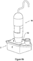
- flask 2 additionally includes a lens 54 that may be molded in the top wall or the bottom walls (not shown) with the focal surface being the first adjacent culture layer.
- the magnification from this lens is 10x to 40x for low level viewing of the cell culture.
- the magnification is 25x to 40x so that visualization of cell growth status and cell detachment during cell recovery is visible with the naked eye.
- a camera system 56 such as the Dino-Lite system (BigC.com Corp., Torrance, Ca) can be secured via a coupling mechanism or mounting system 52 to the top wall 4 or the bottom wall (not shown) to provide image capture.
- this configuration is maintained within the incubator such that monitoring can occur without a researcher having to enter the incubator and disrupt the growth phase of the cells.
- the use of a wireless connection permits the remote monitoring of the cell culture (not shown).
- flask 2 may also include one or more of the following features a) an overmolded seal plastic seal 57 around the perimeter of the flask; b) a non-skid, preferably plastic, button 55 to secure the flask 2 from slipping during the recovery of spent media, cell post cultures or the like when the flask is tipped; c) overmolded plastic ribs or other such feature that provides a user with a non-slip gripping or handling surface.
- the plastic used to make these features comprises a thermoplastic elastomer (TPE) with a hard durometer greater than 49 shore A in order to provide the user an appropriate tactile feel for gripping or otherwise handling the flask.
- TPE thermoplastic elastomer
- flask 2 may also include an easy to open tear-away element 60 or the like in one of the sidewalls 8, wherein the easy to open tear- away element 60 is preferably a component of the overmolded seal 57.
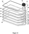
- a multitier cell cultivating multitier flask 100 comprising a cover 94 including a top plate 98, side walls 96 and a resealable port 20; an intermediate tray 92 tor receiving cells and a cell culture media 105, the intermediate tray having a bottom plate 95, side walls 97, and a gap region 89 formed between an interior upwardly angled lip 78 having a swooping curvilinear interior edge 99 located on an interior portion of the bottom plate and an adjacent outwardly angled side wall 87 of the bottom plate; and a base tray 90 for receiving cells and a cell culture media, including a bottom plate 93 and side walls 91 , wherein the tray is positioned between the cover and the base tray, such that the gap region of the bottom plate of the tray is in alignment with the port located on the cover, resulting in the cover, the tray and the base tray in fluid communication with one another which enables a user to directly access each of the cell media located on the tray and the base tray.
- a cell cultivating flask 100 includes a cover 94 having a top plate 98, one or more side walls 96 and a resealable port 20; a plurality of intermediate trays 92 for receiving cells and a cell culture media 105, each intermediate tray 92 having a bottom plate 95, one or more side walls 97, and a gap region 89 formed between an interior upwardly angled lip 78 having a swooping curvilinear interior edge 99 located on an interior portion of the bottom plate and an adjacent outwardly angled side wall 87 of the bottom plate; and a base tray 90 for receiving cells and a cell culture media, having a bottom plate 93 and one or more side walls 91.
- the plurality of intermediate trays 92 are positioned between the cover 94 and the base tray 90, such that the plurality of intermediate trays are stacked on top of one another, and the gap regions of the bottom plates 95 of each intermediate tray are in alignment with each other and with the port located on the cover, resulting in the port, the plurality of intermediate trays and the base tray in fluid communication with one another which enables a user to directly access each of the cell media located on the plurality of intermediate trays and base tray, with a standard pipetting device and the like.
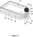
- the side walls 97 on each intermediate tray 92 stacked on top of one another are preferably fused to form a liquid tight seal 135, to the underside of the side walls 97 on next adjoining intermediate tray.
- the side walls on each intermediate tray stacked on top of one another are ultrasonically welded 135 to the underside of the side walls of the next adjoining intermediate tray 92; the side wall of the intermediate tray 92 adjacent the cover 94 is ultrasonically welded 145 to the underside of the side wall of the cover 94, and the side wall of the base tray 90 is ultrasonically welded 155 to the underside of the side wall of the adjoining intermediate tray 92.
- the resealable port 20 can be selectively opened and closed.
- One such means for selectively opening and closing the port 20 is a cap 22, which can be threaded and preferably has a vent 24 that allows for the transfer of gases into and out of the interior 10 without contamination.
- This can be accomplished by using a frit, metal such as stainless steel or plastic such as a POREX® frit or a hydrophobic membrane or filter, all of which have a pore size designed to keep out bacteria, dust and other such contaminants.
- a typical pore size used in such a frit or filter or membrane is less than about 0.65 micron, preferably less than about 0.4 micron and more preferably about 0.22 micron.
- a multitier cell cultivating flask 100, 110, 115 includes a bottom wall 88 of a base tray 90 having a first substantially flat portion 86 and a second substantially flat portion 84 connected to each other by a substantially planar interconnecting portion 81 that is on an angle so as to connect the portions 84 and 86 together.
- base tray 90 includes first portion 86 configured as a substantially horizontal plane that is below the second substantially horizontal plane of the second portion 84 such that media, cells and the like 105 will evenly disperse along the upper surface of base tray 90 because angled portion 81 prevents cells and media 105 from pooling on portion 84.
- first portion 86 of base tray 90 is the lowermost portion of the interior 120 of the device 110.
- each tray equally fills with media 105.
- each tray equally fills with media 105 again.
- a portion of the interior 120 contains one or more cell growing trays 92.
- These trays have a substantially flat bottom portion 76, a substantially planar lip portion 78 that is on an upward angle away from the substantially flat bottom 76 of each tray 92, and sidewalls 97 that run around the periphery of the tray 92.
- the lip portion 78 has an interior edge portion 99.
- the number of sidewalls 97 of the tray(s) 92 is equal in number to the number of sidewalls of the flask 110.
- the front sidewall 87 of the tray(s) is different than the rest of the sidewalls 97 of the tray(s) 92 in that it is angled outward and away from the interior swooping curvilinear edge 99 of the lip 78 of the bottom portion of the trays.
- the front sidewall 87 and the interior curvilinear edge 99 of the lip portion 78 provides open access or a gap region 89 to each tray for cells, liquids and gases 105 when arranged within the flask 110.
Landscapes
- Health & Medical Sciences (AREA)
- Life Sciences & Earth Sciences (AREA)
- Engineering & Computer Science (AREA)
- Wood Science & Technology (AREA)
- Organic Chemistry (AREA)
- Bioinformatics & Cheminformatics (AREA)
- Chemical & Material Sciences (AREA)
- Zoology (AREA)
- Biomedical Technology (AREA)
- Genetics & Genomics (AREA)
- Sustainable Development (AREA)
- Microbiology (AREA)
- Biotechnology (AREA)
- Biochemistry (AREA)
- General Engineering & Computer Science (AREA)
- General Health & Medical Sciences (AREA)
- Clinical Laboratory Science (AREA)
- Molecular Biology (AREA)
- Immunology (AREA)
- Apparatus Associated With Microorganisms And Enzymes (AREA)
Claims (14)
- Ein Zellkultivierungsbehälter (2;100;110;115) mit:einer Abdeckung (94), die eine obere Platte (98), eine Seitenwand (96) und einen wiederverschließbaren Port (20) aufweist,einer oder mehreren Zwischenlade(n) (30;92) zum Aufnehmen von Zellen und Zellenmedien, wobei jede Zwischenlade (30;92) eine untere Platte (95), eine Unterseite, eine Oberseite, eine Seitenwand (97) und einen Zwischenraumbereich (89), der zwischen einer aufwärts gewinkelten Innenlippe (36;78) mit einem Rand (99) befindlich an bzw. auf einem Innenabschnitt der unteren Platte (95) und einem angrenzenden Seitenwandabschnitt (87) der unteren Platte (95) ausgebildet ist, undeiner Basislade (90) zur Aufnahme von Zellen und Zellenmedien, wobei die Basislade (90) eine untere Platte (93), eine Oberseite und eine Seitenwand (91) aufweist, wobei die untere Platte (93) einen ersten im Wesentlichen flachen Abschnitt (24;86), einen zweiten im Wesentlichen flachen Abschnitt (26;84), der sich über der Ebene des ersten flachen Abschnitts (24;86) befindet und mit dem ersten flachen Abschnitt (24;86) durch einen Verbindungsabschnitt (28;81) verbunden ist, welcher sich unter einem Winkel so befindet, dass er die ersten und zweiten flachen Abschnitte (24,26;86,84) miteinander verbindet, aufweist,wobei die Zwischenlade(n) (30;92) zwischen der Abdeckung (94) und der Basislade (90) positioniert ist/sind, und der/die Zwischenraumbereich/Zwischenraumbereiche (89) der Zwischenlade(n) (30;92) und der zweite flache Abschnitt (26;84) der Basislade (90) in Ausrichtung mit dem Port (20) an der Abdeckung (94) sind, was darin resultiert, dass der Port (20), die Zwischenlade(n) (30;92) und die Basislade (90) in Fluidverbindung miteinander sind, und direkten Zugang zu Zellen und Zellenmedien vorsehen, wenn diese sich auf jeder der Zwischen- und Basisladen (30;92,90) befinden.
- Der Behälter (2;110) gemäß Anspruch 1, wobei eine Vielzahl von Zwischenladen (30;92) aufeinander gestapelt sind, und die Zwischenraumbereiche (89) von jeder Zwischenlade (30;92) miteinander und mit dem Port (20) an der Abdeckung (94) ausgerichtet sind bzw. fluchten.
- Der Behälter (110) gemäß Anspruch 2, wobei die Seitenwand (97) von jeder Zwischenlade (92), die aufeinander gestapelt sind, durch eine flüssigkeitsdichte Versiegelung oder Verbindung (135) mit der Unterseite der nächsten angrenzenden Zwischenlade (92) verschmolzen ist.
- Der Behälter (110) gemäß Anspruch 3, wobei die Seitenwand (97) der Zwischenlade (92) angrenzend an die Abdeckung (94) durch eine flüssigkeitsdichte Versiegelung oder eine Verbindung (145) mit der Unterseite der Abdeckung (94) verschmolzen ist, und die Seitenwand (91) der Basislade (90) durch eine flüssigkeitsdichte Versiegelung oder Verbindung (155) mit der Unterseite der angrenzenden Zwischenlade (92) verschmolzen ist.
- Der Behälter (110) gemäß Anspruch 3 oder 4, wobei die flüssigkeitsdichte Versiegelung (135,145,155) durch Ultraschallschweißung gebildet ist.
- Der Behälter (2;100;110;115) gemäß einem der Ansprüche 1 bis 5, wobei der wiederverschließbare Port (20) eine Gewindekappe (22) aufweist.
- Der Behälter (2;100;110;115) gemäß Anspruch 6, wobei die Gewindekappe (22) eine Belüftung (24) aufweist, vorzugsweise in der Form eines luftdurchlässigen Gewebes, die in Verbindung mit einem Innenraum des Behälters (2;100;110;115) ist.
- Der Behälter (2;100;110;115) gemäß Anspruch 7, wobei die Belüftung (24) eine Fritte oder ein Filter aus einer Membran mit einer Porengröße von weniger als etwa 0,65 µm vorzugsweise weniger als etwa 0,4 µm, vorzugsweise weniger als etwa 0,22 µm, vorzugsweise von etwa 0,22 µm ist.
- Der Behälter (2;100;110;115) gemäß einem der Ansprüche 1 bis 8, wobei eine pipettenartige Vorrichtung oder Spritze verwendet werden kann, um Zellen und Zellen-Kultivierungsmedien den Zwischen- oder Basisladen durch den Port (20) hinzuzufügen oder von diesen zu entfernen.
- Der Behälter (2;100;110;115) gemäß einem der Ansprüche 1 bis 9, wobei der Behälter (100;110;115) aus einem Material gemacht ist, das aus der Gruppe bestehend aus einem Polymer, Glas oder einer Kombination davon ausgewählt ist.
- Der Behälter (2;100;110;115) gemäß Anspruch 10, wobei das Material transparent, transluzent, opak, einfarbig, mehrfarbig oder Kombinationen davon ist.
- Der Behälter (2;100;110;115) gemäß einem der Ansprüche 1 bis 11, wobei der Winkel des Verbindungsabschnitts (28;81) gleich oder größer ist als der Winkel der aufwärts gewinkelten Lippe (36;78) der unteren Platte (95) der Zwischenlade(n) (30;92).
- Der Behälter (2;100;110;115) gemäß einem der Ansprüche 1 bis 12, wobei der Winkel des Verbindungsabschnitts (28;81) von etwa 10 Grad bis etwa 60 Grad, vorzugsweise von etwa 10 Grad bis etwa 45 Grad, vorzugsweise von etwa 15 Grad bis etwa 30 Grad, vorzugsweise 22 Grad beträgt.
- Ein Verfahren des Verwendens eines mehrlagigen Zellkulturbehälters mit:a) Vorsehen eines Zellkultivierungsbehälters (2;100;110;115) gemäß einem der Ansprüche 1 bis 13,b) Vorsehen von Zellen und Zellenmedien (105),c) Hinzufügen der Zellen und Zellenmedien (105) zu dem Behälter (100;110;115) durch den Port (20) durch eine pipettenartige Vorrichtung oder eine Spritze,d) Wachsenlassen der Zellen in dem Behälter (100;110;115) für eine bestimmte Zeitspanne und unter gewünschten Bedingungen, unde) Entfernen der Zellen und/oder Medien aus dem Behälter (100;110;115) durch den Port (20) über eine pipettenartige Vorrichtung oder eine Spritze.
Applications Claiming Priority (3)
| Application Number | Priority Date | Filing Date | Title |
|---|---|---|---|
| US13498508P | 2008-07-16 | 2008-07-16 | |
| US20768309P | 2009-02-14 | 2009-02-14 | |
| PCT/US2009/004118 WO2010008566A2 (en) | 2008-07-16 | 2009-07-16 | A single or multitier cell culture system |
Publications (2)
| Publication Number | Publication Date |
|---|---|
| EP2304019A2 EP2304019A2 (de) | 2011-04-06 |
| EP2304019B1 true EP2304019B1 (de) | 2019-04-10 |
Family
ID=41550918
Family Applications (1)
| Application Number | Title | Priority Date | Filing Date |
|---|---|---|---|
| EP09788926.5A Active EP2304019B1 (de) | 2008-07-16 | 2009-07-16 | Schichtiges kolbensystem zur kultivierung von zellen |
Country Status (6)
| Country | Link |
|---|---|
| US (1) | US9783769B2 (de) |
| EP (1) | EP2304019B1 (de) |
| JP (1) | JP5175396B2 (de) |
| CN (1) | CN102099459B (de) |
| ES (1) | ES2733631T3 (de) |
| WO (1) | WO2010008566A2 (de) |
Families Citing this family (52)
| Publication number | Priority date | Publication date | Assignee | Title |
|---|---|---|---|---|
| US8778669B2 (en) | 2009-07-22 | 2014-07-15 | Corning Incorporated | Multilayer tissue culture vessel |
| CN102762713B (zh) | 2010-01-20 | 2016-04-27 | Emd密理博公司 | 细胞图像捕捉和远程监控系统 |
| USD673292S1 (en) | 2010-06-18 | 2012-12-25 | Emd Millipore Corporation | Multilayer cell culture flask |
| USD679829S1 (en) | 2010-06-18 | 2013-04-09 | Emd Millipore Corporation | Multilayer cell culture flask |
| EP2627572A4 (de) | 2010-10-12 | 2017-12-13 | Nalge Nunc International Corporation | Entlüftungsverschluss mit einem port |
| CA2814406A1 (en) * | 2010-10-12 | 2012-04-19 | Nalge Nunc International Corporation | Cell culture device |
| NL2007734C2 (nl) * | 2011-11-07 | 2013-05-08 | Tulip Life Science Products B V | Inrichting voor het kweken van cellen. |
| EP3023785B1 (de) * | 2011-12-20 | 2017-05-10 | Ascensia Diabetes Care Holdings AG | Analytmessgerät mit aufbewahrung von testsensoren in zusammenklappbaren fächern |
| JP2015505472A (ja) * | 2012-02-02 | 2015-02-23 | コーニング インコーポレイテッド | 細胞培養システム |
| CA2872191C (en) | 2012-05-31 | 2018-05-22 | Bayer Healthcare Llc | Replaceable multistrip cartridge and biosensor meter |
| US9204829B2 (en) | 2012-05-31 | 2015-12-08 | Bayer Healthcare Llc | Multistrip cartridge |
| CA2884865A1 (en) * | 2012-09-18 | 2014-03-27 | Bayer Technology Services Gmbh | Disposable bottle reactor tank |
| CN102864076A (zh) * | 2012-09-26 | 2013-01-09 | 无锡耐思生物科技有限公司 | 细胞培养瓶结构 |
| US20140120607A1 (en) * | 2012-10-26 | 2014-05-01 | Corning Incorporated | Multi-Layered Cell Culture Vessel |
| US9005550B2 (en) | 2012-10-29 | 2015-04-14 | Corning Incorporated | Multi-layered cell culture vessel with manifold grips |
| US10533949B2 (en) | 2013-03-12 | 2020-01-14 | Ascensia Diabetes Care Holdings Ag | Test strip meter with a mechanism for pushing the test strip against an optical reader |
| US9790465B2 (en) | 2013-04-30 | 2017-10-17 | Corning Incorporated | Spheroid cell culture well article and methods thereof |
| JP6307802B2 (ja) * | 2013-07-05 | 2018-04-11 | 株式会社Ihi | 培養容器 |
| JP2015050964A (ja) * | 2013-09-06 | 2015-03-19 | 住友ベークライト株式会社 | 多段式培養フラスコおよび細胞培養フラスコの製造方法 |
| JP2016077186A (ja) * | 2014-10-14 | 2016-05-16 | 大日本印刷株式会社 | 培養容器及びその下部容器 |
| EP3212759A1 (de) | 2014-10-29 | 2017-09-06 | Corning Incorporated | Zellkultureinsatz |
| JP2017532971A (ja) | 2014-10-29 | 2017-11-09 | コーニング インコーポレイテッド | 細胞培養集合体を生成するためのマイクロウェル設計および製造 |
| EP3212760A1 (de) | 2014-10-29 | 2017-09-06 | Corning Incorporated | Perfusionsbioreaktorplattform |
| WO2017025584A1 (en) * | 2015-08-12 | 2017-02-16 | Cytovac A/S | A cell cultivation method, a cell cultivation vessel, and uses thereof |
| JP6832586B2 (ja) | 2015-11-06 | 2021-02-24 | 学校法人日本大学 | 培養容器 |
| CN106244457B (zh) * | 2016-08-22 | 2018-08-03 | 日照安维信生物科技有限公司 | 一种试验用培养载体结构 |
| CN106222089B (zh) * | 2016-08-22 | 2018-09-21 | 王铁苗 | 一种试验辅助培养装置 |
| CN106222090B (zh) * | 2016-08-22 | 2018-07-24 | 王铁苗 | 一种试验辅助载体 |
| CN106282017B (zh) * | 2016-08-22 | 2018-09-21 | 王铁苗 | 一种集成式样本培养装置 |
| CN106047703B (zh) * | 2016-08-22 | 2018-08-10 | 青岛爱博生物科技有限公司 | 一种试验样本培养装置 |
| CN106467893B (zh) * | 2016-08-22 | 2018-07-24 | 王铁苗 | 一种试验辅助装置 |
| CN106190843B (zh) * | 2016-08-22 | 2018-06-15 | 刘力伟 | 一种多样本培养装置 |
| CN106222087B (zh) * | 2016-08-22 | 2018-07-24 | 王铁苗 | 一种样本培养载体 |
| US11857970B2 (en) | 2017-07-14 | 2024-01-02 | Corning Incorporated | Cell culture vessel |
| JP7197557B2 (ja) | 2017-07-14 | 2022-12-27 | コーニング インコーポレイテッド | 多孔性支持体を有する細胞培養槽 |
| JP7245222B2 (ja) | 2017-07-14 | 2023-03-23 | コーニング インコーポレイテッド | 手動又は自動で培地を交換するための3d細胞培養容器 |
| PL3652292T3 (pl) | 2017-07-14 | 2025-09-01 | Corning Incorporated | Naczynie do hodowli komórkowej 3d i sposoby hodowli komórkowej 3d |
| WO2019014627A1 (en) * | 2017-07-14 | 2019-01-17 | Corning Incorporated | HANDLING ELEMENTS FOR MICROCAVITY CELL CULTURE CONTAINER |
| WO2019090211A1 (en) * | 2017-11-06 | 2019-05-09 | Corning Incorporated | Cell culture apparatuses with manifolds including column structures |
| WO2020013845A1 (en) | 2018-07-13 | 2020-01-16 | Corning Incorporated | Cell culture vessels with stabilizer devices |
| CN111065725B (zh) | 2018-07-13 | 2024-03-29 | 康宁股份有限公司 | 包括具有互联的壁的微板的流体装置 |
| JP7171695B2 (ja) * | 2018-07-13 | 2022-11-15 | コーニング インコーポレイテッド | 液体培地送達面を含む側壁を有するマイクロキャビティ皿 |
| CN109207363A (zh) * | 2018-09-20 | 2019-01-15 | 南京至泰生物医药科技有限公司 | 层流式活细胞培养设备 |
| USD907244S1 (en) | 2019-06-14 | 2021-01-05 | Emd Millipore Corporation | Cell imager |
| JP2020202784A (ja) * | 2019-06-17 | 2020-12-24 | シンフォニアテクノロジー株式会社 | 多層培養容器 |
| EP3998329A4 (de) | 2019-07-08 | 2023-08-02 | Nipro Corporation | Mehrschichtiges kulturgefäss |
| AU2020322793A1 (en) * | 2019-07-29 | 2022-03-03 | Vitrolabs Inc | Scalable bioreactor systems and methods for tissue engineering |
| KR102411446B1 (ko) * | 2019-10-17 | 2022-06-23 | 주식회사 아모그린텍 | 세포배양장치 |
| WO2022108968A2 (en) * | 2020-11-20 | 2022-05-27 | Corning Incorporated | Open-well microcavity plate |
| WO2024118201A1 (en) * | 2022-11-28 | 2024-06-06 | Corning Incorporated | Cell culture device including at least one notch formed in a sidewall for exchange of fluid media |
| DE202023100040U1 (de) * | 2023-01-05 | 2024-04-08 | Thermo Electron Led Gmbh | Einlegesystem |
| WO2026010861A1 (en) * | 2024-07-03 | 2026-01-08 | Corning Incorporated | Multi-functional cell culture flask and its use in t-cell therapies |
Citations (1)
| Publication number | Priority date | Publication date | Assignee | Title |
|---|---|---|---|---|
| US20070065933A1 (en) * | 2003-02-28 | 2007-03-22 | Peter Esser | Tray stack adapted for active gassing |
Family Cites Families (21)
| Publication number | Priority date | Publication date | Assignee | Title |
|---|---|---|---|---|
| US4228243A (en) * | 1978-07-13 | 1980-10-14 | Toray Industries, Inc. | Cell culture propagation apparatus |
| US5139952A (en) * | 1983-09-16 | 1992-08-18 | Terumo Corporation | Tissue culture flask |
| US4770854A (en) * | 1986-02-03 | 1988-09-13 | Costar Corporation | Laboratory flask |
| US4734373A (en) | 1986-06-24 | 1988-03-29 | Bartal Arie H | Apparatus for enhancing cell growth, preservation and transport |
| EP0500549B1 (de) * | 1990-09-19 | 1996-05-08 | BERRY, Eric, Scott | Kontinuierliche zellkulturanlage von hoher dichtheit |
| JPH04262775A (ja) * | 1990-10-18 | 1992-09-18 | Costar Corp | 連続式細胞培養装置 |
| US5310676A (en) * | 1991-11-15 | 1994-05-10 | A/S Nunc | Cell cultivating device |
| US5695987A (en) * | 1996-08-08 | 1997-12-09 | Becton Dickinson And Company | Reusable vented flask cap cover |
| US6764688B2 (en) * | 1996-09-03 | 2004-07-20 | Kaneka Corporation | Method for inducing immunosuppressive cells and a culture device to be used therefor |
| US5783440A (en) * | 1996-09-30 | 1998-07-21 | Becton Dickinson And Company | Culture vessel |
| US6107085A (en) * | 1997-07-11 | 2000-08-22 | Corning Incorporated | Self contained cell growth system |
| US6569675B2 (en) * | 2000-06-16 | 2003-05-27 | Corning Incorporated | Cell cultivating flask and method for using the cell cultivating flask |
| CN101120083B (zh) * | 2003-10-08 | 2013-03-27 | 威尔森沃尔夫制造公司 | 利用透气性材料进行细胞培养的方法及装置 |
| EP1863897A1 (de) * | 2005-03-14 | 2007-12-12 | Corning Inc. | Zellkultivierungskolben |
| WO2006101056A1 (ja) * | 2005-03-22 | 2006-09-28 | Medinet Co., Ltd. | 細胞培養評価システム、細胞培養評価方法および細胞培養評価プログラム |
| US7745209B2 (en) * | 2005-07-26 | 2010-06-29 | Corning Incorporated | Multilayered cell culture apparatus |
| CA2616622C (en) * | 2005-08-01 | 2016-09-20 | Invitrogen Corporation | Labels, containers, systems and methods for providing reagents |
| US20080118974A1 (en) | 2006-11-20 | 2008-05-22 | Gregory Roger Martin | Large scale cell culture vessel |
| US7897379B2 (en) * | 2007-02-26 | 2011-03-01 | Corning Incorporated | Device and method for reducing bubble formation in cell culture |
| US20090148941A1 (en) * | 2007-07-30 | 2009-06-11 | Peter Florez | Disposable mini-bioreactor device and method |
| EP2330735A3 (de) | 2008-07-18 | 2012-04-04 | Peregrine Semiconductor Corporation | Transkonduktanz-Operationsverstärker |
-
2009
- 2009-07-16 EP EP09788926.5A patent/EP2304019B1/de active Active
- 2009-07-16 WO PCT/US2009/004118 patent/WO2010008566A2/en not_active Ceased
- 2009-07-16 US US12/460,265 patent/US9783769B2/en active Active
- 2009-07-16 ES ES09788926T patent/ES2733631T3/es active Active
- 2009-07-16 JP JP2011518730A patent/JP5175396B2/ja active Active
- 2009-07-16 CN CN2009801280863A patent/CN102099459B/zh active Active
Patent Citations (1)
| Publication number | Priority date | Publication date | Assignee | Title |
|---|---|---|---|---|
| US20070065933A1 (en) * | 2003-02-28 | 2007-03-22 | Peter Esser | Tray stack adapted for active gassing |
Also Published As
| Publication number | Publication date |
|---|---|
| JP2011528226A (ja) | 2011-11-17 |
| CN102099459B (zh) | 2013-05-01 |
| WO2010008566A2 (en) | 2010-01-21 |
| WO2010008566A3 (en) | 2010-05-27 |
| US9783769B2 (en) | 2017-10-10 |
| US20160137961A2 (en) | 2016-05-19 |
| EP2304019A2 (de) | 2011-04-06 |
| JP5175396B2 (ja) | 2013-04-03 |
| ES2733631T3 (es) | 2019-12-02 |
| CN102099459A (zh) | 2011-06-15 |
| US20100129900A1 (en) | 2010-05-27 |
Similar Documents
| Publication | Publication Date | Title |
|---|---|---|
| EP2304019B1 (de) | Schichtiges kolbensystem zur kultivierung von zellen | |
| US7897379B2 (en) | Device and method for reducing bubble formation in cell culture | |
| CA2551940C (en) | Containers and methods for the automated handling of a liquid | |
| JP2573793B2 (ja) | 培養容器 | |
| US5554536A (en) | Biological analysis device having improved contamination prevention | |
| JP5107919B2 (ja) | 多層型細胞培養装置 | |
| EP3148700B1 (de) | Einspaltiges mikroplattensystem und träger zur analyse biologischer proben | |
| EP2085463B1 (de) | Kulturplatte mit Klappe zur seitlichen Belüftung | |
| JP2013172747A (ja) | アクセス制限された多層細胞培養システム | |
| JP2011501689A (ja) | マイクロリアクタ | |
| US8323957B2 (en) | Device and method for the incubation of cells | |
| JPS60102184A (ja) | 培養フラスコ | |
| EP0773286A2 (de) | Träger für Deckgläser | |
| EP2029279A2 (de) | Mikrotiterplatte für langzeitlagerung | |
| JP2005502571A (ja) | 試料を作成する反応容器 | |
| EP3998329A1 (de) | Mehrschichtiges kulturgefäss | |
| US20240368514A1 (en) | Sbs-format single, or dual, deep well stackable cell culture disposable well plate and closure | |
| US20150315536A1 (en) | Cell cultivating flask |
Legal Events
| Date | Code | Title | Description |
|---|---|---|---|
| PUAI | Public reference made under article 153(3) epc to a published international application that has entered the european phase |
Free format text: ORIGINAL CODE: 0009012 |
|
| 17P | Request for examination filed |
Effective date: 20110114 |
|
| AK | Designated contracting states |
Kind code of ref document: A2 Designated state(s): AT BE BG CH CY CZ DE DK EE ES FI FR GB GR HR HU IE IS IT LI LT LU LV MC MK MT NL NO PL PT RO SE SI SK SM TR |
|
| AX | Request for extension of the european patent |
Extension state: AL BA RS |
|
| DAX | Request for extension of the european patent (deleted) | ||
| RAP1 | Party data changed (applicant data changed or rights of an application transferred) |
Owner name: EMD MILLIPORE CORPORATION |
|
| 17Q | First examination report despatched |
Effective date: 20160607 |
|
| GRAP | Despatch of communication of intention to grant a patent |
Free format text: ORIGINAL CODE: EPIDOSNIGR1 |
|
| STAA | Information on the status of an ep patent application or granted ep patent |
Free format text: STATUS: GRANT OF PATENT IS INTENDED |
|
| INTG | Intention to grant announced |
Effective date: 20181018 |
|
| GRAS | Grant fee paid |
Free format text: ORIGINAL CODE: EPIDOSNIGR3 |
|
| GRAA | (expected) grant |
Free format text: ORIGINAL CODE: 0009210 |
|
| STAA | Information on the status of an ep patent application or granted ep patent |
Free format text: STATUS: THE PATENT HAS BEEN GRANTED |
|
| AK | Designated contracting states |
Kind code of ref document: B1 Designated state(s): AT BE BG CH CY CZ DE DK EE ES FI FR GB GR HR HU IE IS IT LI LT LU LV MC MK MT NL NO PL PT RO SE SI SK SM TR |
|
| REG | Reference to a national code |
Ref country code: GB Ref legal event code: FG4D |
|
| REG | Reference to a national code |
Ref country code: CH Ref legal event code: EP Ref country code: AT Ref legal event code: REF Ref document number: 1118644 Country of ref document: AT Kind code of ref document: T Effective date: 20190415 |
|
| REG | Reference to a national code |
Ref country code: CH Ref legal event code: NV Representative=s name: E. BLUM AND CO. AG PATENT- UND MARKENANWAELTE , CH |
|
| REG | Reference to a national code |
Ref country code: IE Ref legal event code: FG4D |
|
| REG | Reference to a national code |
Ref country code: DE Ref legal event code: R096 Ref document number: 602009057853 Country of ref document: DE |
|
| REG | Reference to a national code |
Ref country code: NL Ref legal event code: FP |
|
| REG | Reference to a national code |
Ref country code: LT Ref legal event code: MG4D |
|
| REG | Reference to a national code |
Ref country code: AT Ref legal event code: MK05 Ref document number: 1118644 Country of ref document: AT Kind code of ref document: T Effective date: 20190410 |
|
| PG25 | Lapsed in a contracting state [announced via postgrant information from national office to epo] |
Ref country code: HR Free format text: LAPSE BECAUSE OF FAILURE TO SUBMIT A TRANSLATION OF THE DESCRIPTION OR TO PAY THE FEE WITHIN THE PRESCRIBED TIME-LIMIT Effective date: 20190410 Ref country code: LT Free format text: LAPSE BECAUSE OF FAILURE TO SUBMIT A TRANSLATION OF THE DESCRIPTION OR TO PAY THE FEE WITHIN THE PRESCRIBED TIME-LIMIT Effective date: 20190410 Ref country code: NO Free format text: LAPSE BECAUSE OF FAILURE TO SUBMIT A TRANSLATION OF THE DESCRIPTION OR TO PAY THE FEE WITHIN THE PRESCRIBED TIME-LIMIT Effective date: 20190710 Ref country code: FI Free format text: LAPSE BECAUSE OF FAILURE TO SUBMIT A TRANSLATION OF THE DESCRIPTION OR TO PAY THE FEE WITHIN THE PRESCRIBED TIME-LIMIT Effective date: 20190410 Ref country code: PT Free format text: LAPSE BECAUSE OF FAILURE TO SUBMIT A TRANSLATION OF THE DESCRIPTION OR TO PAY THE FEE WITHIN THE PRESCRIBED TIME-LIMIT Effective date: 20190910 Ref country code: SE Free format text: LAPSE BECAUSE OF FAILURE TO SUBMIT A TRANSLATION OF THE DESCRIPTION OR TO PAY THE FEE WITHIN THE PRESCRIBED TIME-LIMIT Effective date: 20190410 |
|
| PG25 | Lapsed in a contracting state [announced via postgrant information from national office to epo] |
Ref country code: BG Free format text: LAPSE BECAUSE OF FAILURE TO SUBMIT A TRANSLATION OF THE DESCRIPTION OR TO PAY THE FEE WITHIN THE PRESCRIBED TIME-LIMIT Effective date: 20190710 Ref country code: LV Free format text: LAPSE BECAUSE OF FAILURE TO SUBMIT A TRANSLATION OF THE DESCRIPTION OR TO PAY THE FEE WITHIN THE PRESCRIBED TIME-LIMIT Effective date: 20190410 Ref country code: PL Free format text: LAPSE BECAUSE OF FAILURE TO SUBMIT A TRANSLATION OF THE DESCRIPTION OR TO PAY THE FEE WITHIN THE PRESCRIBED TIME-LIMIT Effective date: 20190410 Ref country code: GR Free format text: LAPSE BECAUSE OF FAILURE TO SUBMIT A TRANSLATION OF THE DESCRIPTION OR TO PAY THE FEE WITHIN THE PRESCRIBED TIME-LIMIT Effective date: 20190711 |
|
| REG | Reference to a national code |
Ref country code: ES Ref legal event code: FG2A Ref document number: 2733631 Country of ref document: ES Kind code of ref document: T3 Effective date: 20191202 |
|
| PG25 | Lapsed in a contracting state [announced via postgrant information from national office to epo] |
Ref country code: AT Free format text: LAPSE BECAUSE OF FAILURE TO SUBMIT A TRANSLATION OF THE DESCRIPTION OR TO PAY THE FEE WITHIN THE PRESCRIBED TIME-LIMIT Effective date: 20190410 Ref country code: IS Free format text: LAPSE BECAUSE OF FAILURE TO SUBMIT A TRANSLATION OF THE DESCRIPTION OR TO PAY THE FEE WITHIN THE PRESCRIBED TIME-LIMIT Effective date: 20190810 |
|
| REG | Reference to a national code |
Ref country code: DE Ref legal event code: R097 Ref document number: 602009057853 Country of ref document: DE |
|
| PG25 | Lapsed in a contracting state [announced via postgrant information from national office to epo] |
Ref country code: EE Free format text: LAPSE BECAUSE OF FAILURE TO SUBMIT A TRANSLATION OF THE DESCRIPTION OR TO PAY THE FEE WITHIN THE PRESCRIBED TIME-LIMIT Effective date: 20190410 Ref country code: DK Free format text: LAPSE BECAUSE OF FAILURE TO SUBMIT A TRANSLATION OF THE DESCRIPTION OR TO PAY THE FEE WITHIN THE PRESCRIBED TIME-LIMIT Effective date: 20190410 Ref country code: CZ Free format text: LAPSE BECAUSE OF FAILURE TO SUBMIT A TRANSLATION OF THE DESCRIPTION OR TO PAY THE FEE WITHIN THE PRESCRIBED TIME-LIMIT Effective date: 20190410 Ref country code: RO Free format text: LAPSE BECAUSE OF FAILURE TO SUBMIT A TRANSLATION OF THE DESCRIPTION OR TO PAY THE FEE WITHIN THE PRESCRIBED TIME-LIMIT Effective date: 20190410 Ref country code: SK Free format text: LAPSE BECAUSE OF FAILURE TO SUBMIT A TRANSLATION OF THE DESCRIPTION OR TO PAY THE FEE WITHIN THE PRESCRIBED TIME-LIMIT Effective date: 20190410 |
|
| PLBE | No opposition filed within time limit |
Free format text: ORIGINAL CODE: 0009261 |
|
| STAA | Information on the status of an ep patent application or granted ep patent |
Free format text: STATUS: NO OPPOSITION FILED WITHIN TIME LIMIT |
|
| PG25 | Lapsed in a contracting state [announced via postgrant information from national office to epo] |
Ref country code: SM Free format text: LAPSE BECAUSE OF FAILURE TO SUBMIT A TRANSLATION OF THE DESCRIPTION OR TO PAY THE FEE WITHIN THE PRESCRIBED TIME-LIMIT Effective date: 20190410 Ref country code: MC Free format text: LAPSE BECAUSE OF FAILURE TO SUBMIT A TRANSLATION OF THE DESCRIPTION OR TO PAY THE FEE WITHIN THE PRESCRIBED TIME-LIMIT Effective date: 20190410 |
|
| 26N | No opposition filed |
Effective date: 20200113 |
|
| PG25 | Lapsed in a contracting state [announced via postgrant information from national office to epo] |
Ref country code: TR Free format text: LAPSE BECAUSE OF FAILURE TO SUBMIT A TRANSLATION OF THE DESCRIPTION OR TO PAY THE FEE WITHIN THE PRESCRIBED TIME-LIMIT Effective date: 20190410 |
|
| PG25 | Lapsed in a contracting state [announced via postgrant information from national office to epo] |
Ref country code: LU Free format text: LAPSE BECAUSE OF NON-PAYMENT OF DUE FEES Effective date: 20190716 Ref country code: SI Free format text: LAPSE BECAUSE OF FAILURE TO SUBMIT A TRANSLATION OF THE DESCRIPTION OR TO PAY THE FEE WITHIN THE PRESCRIBED TIME-LIMIT Effective date: 20190410 |
|
| PG25 | Lapsed in a contracting state [announced via postgrant information from national office to epo] |
Ref country code: IE Free format text: LAPSE BECAUSE OF NON-PAYMENT OF DUE FEES Effective date: 20190716 |
|
| PG25 | Lapsed in a contracting state [announced via postgrant information from national office to epo] |
Ref country code: CY Free format text: LAPSE BECAUSE OF FAILURE TO SUBMIT A TRANSLATION OF THE DESCRIPTION OR TO PAY THE FEE WITHIN THE PRESCRIBED TIME-LIMIT Effective date: 20190410 |
|
| PG25 | Lapsed in a contracting state [announced via postgrant information from national office to epo] |
Ref country code: HU Free format text: LAPSE BECAUSE OF FAILURE TO SUBMIT A TRANSLATION OF THE DESCRIPTION OR TO PAY THE FEE WITHIN THE PRESCRIBED TIME-LIMIT; INVALID AB INITIO Effective date: 20090716 Ref country code: MT Free format text: LAPSE BECAUSE OF FAILURE TO SUBMIT A TRANSLATION OF THE DESCRIPTION OR TO PAY THE FEE WITHIN THE PRESCRIBED TIME-LIMIT Effective date: 20190410 |
|
| PG25 | Lapsed in a contracting state [announced via postgrant information from national office to epo] |
Ref country code: MK Free format text: LAPSE BECAUSE OF FAILURE TO SUBMIT A TRANSLATION OF THE DESCRIPTION OR TO PAY THE FEE WITHIN THE PRESCRIBED TIME-LIMIT Effective date: 20190410 |
|
| P01 | Opt-out of the competence of the unified patent court (upc) registered |
Effective date: 20230602 |
|
| PGFP | Annual fee paid to national office [announced via postgrant information from national office to epo] |
Ref country code: GB Payment date: 20250619 Year of fee payment: 17 |
|
| PGFP | Annual fee paid to national office [announced via postgrant information from national office to epo] |
Ref country code: NL Payment date: 20250620 Year of fee payment: 17 Ref country code: BE Payment date: 20250619 Year of fee payment: 17 |
|
| PGFP | Annual fee paid to national office [announced via postgrant information from national office to epo] |
Ref country code: FR Payment date: 20250620 Year of fee payment: 17 |
|
| PGFP | Annual fee paid to national office [announced via postgrant information from national office to epo] |
Ref country code: ES Payment date: 20250801 Year of fee payment: 17 |
|
| PGFP | Annual fee paid to national office [announced via postgrant information from national office to epo] |
Ref country code: DE Payment date: 20250620 Year of fee payment: 17 |
|
| PGFP | Annual fee paid to national office [announced via postgrant information from national office to epo] |
Ref country code: IT Payment date: 20250619 Year of fee payment: 17 |
|
| PGFP | Annual fee paid to national office [announced via postgrant information from national office to epo] |
Ref country code: CH Payment date: 20250801 Year of fee payment: 17 |