EP2304085B1 - Dispositif de guidage de manchon pour un cylindre supérieur d'un train d'étirage - Google Patents
Dispositif de guidage de manchon pour un cylindre supérieur d'un train d'étirage Download PDFInfo
- Publication number
- EP2304085B1 EP2304085B1 EP08802346A EP08802346A EP2304085B1 EP 2304085 B1 EP2304085 B1 EP 2304085B1 EP 08802346 A EP08802346 A EP 08802346A EP 08802346 A EP08802346 A EP 08802346A EP 2304085 B1 EP2304085 B1 EP 2304085B1
- Authority
- EP
- European Patent Office
- Prior art keywords
- apron
- guide
- guide device
- base body
- top roller
- Prior art date
- Legal status (The legal status is an assumption and is not a legal conclusion. Google has not performed a legal analysis and makes no representation as to the accuracy of the status listed.)
- Not-in-force
Links
Images
Classifications
-
- D—TEXTILES; PAPER
- D01—NATURAL OR MAN-MADE THREADS OR FIBRES; SPINNING
- D01H—SPINNING OR TWISTING
- D01H5/00—Drafting machines or arrangements ; Threading of roving into drafting machine
- D01H5/18—Drafting machines or arrangements without fallers or like pinned bars
- D01H5/70—Constructional features of drafting elements
- D01H5/86—Aprons; Apron supports; Apron tensioning arrangements
-
- D—TEXTILES; PAPER
- D01—NATURAL OR MAN-MADE THREADS OR FIBRES; SPINNING
- D01H—SPINNING OR TWISTING
- D01H5/00—Drafting machines or arrangements ; Threading of roving into drafting machine
- D01H5/18—Drafting machines or arrangements without fallers or like pinned bars
- D01H5/26—Drafting machines or arrangements without fallers or like pinned bars in which fibres are controlled by one or more endless aprons
-
- D—TEXTILES; PAPER
- D01—NATURAL OR MAN-MADE THREADS OR FIBRES; SPINNING
- D01H—SPINNING OR TWISTING
- D01H5/00—Drafting machines or arrangements ; Threading of roving into drafting machine
- D01H5/18—Drafting machines or arrangements without fallers or like pinned bars
- D01H5/70—Constructional features of drafting elements
- D01H5/86—Aprons; Apron supports; Apron tensioning arrangements
- D01H5/88—Cradles; Tensors
Definitions
- the invention relates to a Riemchen operations adopted for guiding a drafting a top roller with an elastic cover looping around the belt, the Riemchen Entrys acquired includes a receptacle for the drafting top roller and guide surfaces for the strap.
- a Riemchen entrys worn of this kind is from the DE 103 48 452 A1 known.
- the known Riemchen Operations learned is made in one piece, wherein the straps are subjected substantially only to that tensile stress, which is caused by their endeavor to assume approximately circular shape in the circumferential direction. Due to the one-piece design of the Riemchen operations, issued the Riemchen Operationss issued, in particular in the embodiment as a plastic injection molded part, only consist of a single material. The selection of the material requires compromises, since at different points of the Riemchen Entrys learned different requirements are placed on the material.
- the invention has for its object to improve the Riemchen enclosures worn.
- the Riemchen Installations shark comprises a main body and a base member attached to the guide member, wherein the base body contains the receptacle for the drafting top roller and wherein the guide member includes at least one guide surface for the strap.
- the two-part embodiment of the apron guiding device separates the two most important functions to be achieved by the apron guiding device, namely the guiding of the apron and the fastening of the apron guiding device to the axis of the drafting system upper roller.
- the function of attaching and holding the Riemchen Operationss worn is taken from the body, which contains the receptacle for the axis of the drafting top roller.
- the main body can be made for example of a glass fiber or carbon fiber reinforced plastic. Such a plastic ensures high stability of the body and prevents excessive deformation under the external loading forces.
- the guide surfaces for the strapping are arranged on a guide component separate from the main body.
- the guide component can be fastened to the base body and can be designed such that it is only subjected to very little load by operating forces.
- a particularly slippery plastic which need not contain reinforcement by glass or carbon fibers.
- Gleitfreudiger plastic is particularly suitable a plastic which consists at least in part of polytetrafluoroethylene.
- the wear of the strap can be reduced thereby and the service life of the strap increases.
- the friction losses which require an increased drive torque of the drafting system sub-roller, can be minimized.
- the wear preferably occurs on the guide component, which can optionally be easily and inexpensively replaced.
- the guide member from a wear-resistant material such as ceramic or steel, which is polished on the guide surfaces for the strap.
- Drawframe top rollers in drafting systems for warping staple fiber bundles are often designed as top roller twins.
- An upper roller twin comprises two drafting rollers, each with an elastic reference, which are freely rotatably mounted on a fixed axle. The axle is received in its central region by a load carrier of the drafting system.
- an upper roller twin can also be designed as a so-called fixed roller, in which the two drafting top rollers are rotatably connected to an axle, wherein for supporting the axle, a sleeve is provided which surrounds the axis of the fixed roller and which is then accommodated on the load carrier.
- the upper roller twin is designed as a fixed roller, the receptacle of the main body of the Riemchen extractions liked is of course designed so that the recording on the axis of the drafting top roller surrounding sleeve can be placed.
- the Riemchen Entrys worn for an Oberwalzenzwilling includes two fixed to the main body guide components for the adjacent drafting crown upper rollers.
- the two guide components at different distances from each other on the base body can be fastened, wherein the guide members parallel to the axial direction of the drafting top roller can be displaced and positioning means may be provided for the guide member, which allow attachment of the guide members on the body only at predetermined intervals.
- This embodiment has the advantage that the apron guiding means for different-pitch upper-twin twins, i. Obervvalzenzwillinge with different distances far apart elastic covers of the two drafting crown rolls, is used.
- the Riemchenschreib is only generated by the fact that the straps strives to assume approximately circular shape in the circumferential direction.
- the strap guiding device contains a tensioning element that is spring-loaded.
- the clamping element can be arranged both on the main body and on the guide member and can be formed for example by an additional plastic bottle. It can also be provided that the clamping element are formed by a spring-loaded guide surface of the guide component. For example, the tread alone or the entire guide element can be sprung with tread.
- the Riemchen exchanges worn may include an obliquely arranged to the Riemchenlaufraum scraper edge.
- the wiper edge is used to clean the strap of any adhering fibers.
- the wiper edge can be made to touch the strap slightly or to be non-contact at a minimum distance from the strap.
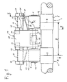
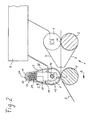
- FIGS. 1 and 2 is a drafting 1 for warping a staple fiber strand 2 shown schematically.
- the drafting 1 consists - as in FIG. 2 recognizable - from a plurality of roller pairs 3, 4 and 5, 6, which transport the staple fiber strand 2 in the transport direction A and distort it to the desired fineness.
- the lower rollers 3 and 5 are driven.
- the upper rollers 4 and 6 are held in a load carrier 7 and are pressed against the lower rollers 3 and 5.
- the pair of rollers 3, 4 are arranged in a conventional manner effetsriemchen 8 and 9 for guiding the staple fiber strand in the drafting zone between the nip line 10 of the pair of rollers 3, 4 and the nip line 11 of the pair of rollers 5, 6.
- the top roller 6 is provided with an elastic cover 12 made of a rubber-like material. To protect the elastic cover 12 against excessive wear by the staple fiber strand 2 of the top roller 6 is associated with a strap 13 which wraps around the elastic cover 12. To guide the strap 13 a Riemchen arrangements worn 14 is provided.
- the Riemchen Operations prepared 14 includes a receptacle 15 for the axis 16 of the drafting top roller 6 and a tread 17 for the strap 13.
- the Riemchen Operations prepared 14 is disposed on the output top roller 6 of the drafting 1, so that the strap 13 forms the nip line 11 at which the Delay of the fiber structure 2 is completed.
- the wear of the upper roller 6 is particularly strong, since there the Urrifangsgeschwirmaschine the rollers 5, 6 is highest.
- drafting units 1 are arranged side by side, as is the case for example with drafting systems ° 1 for ring spinning machines.
- the lower rollers 3 and 5 designed as in the machine longitudinal direction continuous sub-cylinder, as in FIG. 1 to recognize.
- the two drafting top rollers 6 of the adjacent drafting units 1 are arranged freely rotatably on a common axis 16.
- the axle 16 is fixedly received in a holder 18 which is fixed to the Betastungs synonym 17 and through which the drafting top rollers 6 are pressed against the lower roller 5.
- the two top rollers 6 and the axle 16 form a so-called top roller twin.
- the elastic covers 12 of the two upper rollers 6 of the Oberwalzenzwillings 19 are each wrapped by a strap 13.
- the receptacle 15 surrounds the holder 18 fork-shaped and is clipped onto the axis 16.
- the Riemchen Installations worn 14 is designed in two parts and a base body 20 and a guide member 21 for each strap 13 contains.
- the main body contains the receptacle 15 for the axis 16 of the Oberwalzenzwillings 19 and is made of a stable material that can absorb the loading forces occurring during operation.
- the main body 20 is preferably made of a fiber-reinforced plastic.
- the guide member 21 includes the tread 17 and two side guides 22, all of which together are referred to as guide surfaces for the strap 13.
- the guide member consists of a sliding plastic, so that the strap 13 on the guide surfaces 17 and 22 finds little resistance.
- Each guide member 21 is attached via receptacles 23 and 24 on the main body 20.
- the guide component 21 can be pushed onto the base body 20 parallel to the axial direction of the drafting unit upper roller 6.
- positioning means 25 in the form of a pin 26 on the guide member 21 and a plurality of grooves 27 on the base body 20 to ensure positioning of the two guide members 21 at predetermined distances from each other.
- Oberwalzenzwillinge 19 different division B are used.
- the pitch B corresponds to the distance of the distorted in adjacent drafting 1 staple fiber assemblies 2.
- the covers 12 of the Oberwalzenzwillings 19 also have a pitch corresponding to the pitch.
- the side guides 22 of the Riemchen operations worn 14 must be coordinated with the division of Obervvalzenzwillings 19 so that the straps 13 run exactly on the covers 12. Due to the adjustability of the guide members 21 and the positioning means 25, the Riemchen Entrys worn 14 invention Oberwalzenzwillingen 19 different pitch B are used without a large adjustment effort is necessary.
- the number and the position of the grooves 27 in the base body 20 is matched to the divisions used in practice B of Oberwalzenzwillinge 19.
- the replacement of a single strap 13 can be simplified.
- the guide member 21 can be pushed down with the strap 13 in the axial direction of the top rollers 6 from the base body 20.
- the strap does not need to be pulled over the side guide 22. It is thus possible to provide relatively high side guides 22, which still ensure a good guidance of the strap 13, when the elastic cover 12 must be reground and thereby reduces its diameter.
- the increased side guides 22 ensure a safe Riemchen Installation even with reduced diameter of the drafting top roller 6 without an additional clamping element must be present.
- the wiping edge 28 is arranged on the inside of the strap 13 obliquely to Riemchenlaufraum C.
- the wiper edge 28 preferably touches the strap 13 very easily. Due to the inclination of the wiping edge in relation to the Riemchenlaufraum C is possibly stripped on the inside of the strap 13 adhering dirt and conveyed out laterally.
- the strap 13, which wraps around the elastic cover 12 of the drafting top roller 6, can be designed differently.
- the strap 13 may, for example, be designed like a guide strap 8 and have at least on its outer surface a layer of a rubber-like material.
- the strap 13 may also be designed as a so-called Siebriemchen, which consists of an air-permeable fabric. Such Siebriemchen are usually used in the drafting 1 downstream compression equipment for compacting the finished warped staple fiber.
- the scope of the Strap 13 is preferably selected according to the staple length of the fibers present in staple fiber strand 2 and should preferably be greater than the staple length. Such a sized circumference of the strap 13 effectively prevents the formation of unwanted coils on the strap 13, even if the diameter of the drafting top roller 6 is chosen to be relatively small.
- a straight line through the center of the axis 16 and the center of the tread 17 has an angle of about 90 ° to the stretching field plane.
- the drafting system 1 is usually angeorndnet in the ring spinning machine so that the stretching field plane is not horizontal.
- the stretching field plane can, for example, extend at an angle of 45 ° to the floor. It may be advantageous that the angle between the stretching field plane and the straight line defined by the center of the axis 16 and the center of the running surface 17 corresponds approximately to the angle between the stretching field plane and the floor. As a result, the Riemchen extractions worn 14 is approximately horizontal.
- the angle between the stretching field plane and the straight line passing through the center of the axis 16 and the center of the running surface 17 may preferably be about 45 °.
Landscapes
- Engineering & Computer Science (AREA)
- Mechanical Engineering (AREA)
- Textile Engineering (AREA)
- Spinning Or Twisting Of Yarns (AREA)
Abstract
Claims (7)
- Dispositif de guidage de lanière pour le guidage d'une lanière (13) enlaçant un cylindre supérieur (6) de banc d'étirage avec un revêtement élastique (12), sachant que le dispositif de guidage de lanière comporte un logement (15) pour le cylindre supérieur (6) de banc d'étirage et des surfaces de guidage pour la lanière (13), caractérisé en ce que le dispositif de guidage de lanière (14) présente un corps de base (20) et une pièce de guidage (21) fixée audit corps de base (20), sachant que le corps de base (20) comporte le logement (15) pour le cylindre supérieur (6) de banc d'étirage, et sachant que la pièce de guidage (21) présente au moins une surface de guidage (17; 22) pour la lanière (13).
- Dispositif de guidage de lanière selon la revendication 1, caractérisé en ce que le dispositif de guidage de lanière (14) comporte deux pièces de guidage (21) fixées au corps de base (20) pour des cylindres supérieurs (6) de banc d'étirage adjacents d'une paire de cylindres supérieurs (19).
- Dispositif de guidage de lanière selon la revendication 2, caractérisé en ce que les deux pièces de guidage (21) peuvent être fixées au corps de base (20) à des distances différentes l'une de l'autre.
- Dispositif de guidage de lanière selon la revendication 3, caractérisé en ce que le dispositif de guidage de lanière (14) comporte des moyens de positionnement (25) pour les pièces de guidage (21), qui ne permettent un positionnement des pièces de guidage (21) au corps de base (20) qu'à des distances prédéfinies.
- Dispositif de guidage de lanière selon l'une quelconque des revendications 1 à 4, caractérisé en ce qu'une pièce de guidage (21) peut être déplacée parallèlement au sens de l'axe du cylindre supérieur (6) de banc d'étirage.
- Dispositif de guidage de lanière selon l'une quelconque des revendications 1 à 5, caractérisé en ce le dispositif de guidage de lanière (14) comporte un élément de serrage élastique.
- Dispositif de guidage de lanière selon l'une quelconque des revendications 1 à 6, caractérisé en ce que le dispositif de guidage de lanière (14) comporte un bord racleur (28) disposé en diagonale par rapport au sens de coulissement (C) de la lanière.
Applications Claiming Priority (2)
| Application Number | Priority Date | Filing Date | Title |
|---|---|---|---|
| DE102008010364A DE102008010364A1 (de) | 2008-02-18 | 2008-02-18 | Riemchenführungseinrichtung für eine Streckwerksoberwalze |
| PCT/EP2008/007825 WO2009103318A1 (fr) | 2008-02-18 | 2008-09-18 | Dispositif de guidage de manchon pour un cylindre supérieur d'un train d'étirage |
Publications (2)
| Publication Number | Publication Date |
|---|---|
| EP2304085A1 EP2304085A1 (fr) | 2011-04-06 |
| EP2304085B1 true EP2304085B1 (fr) | 2012-05-30 |
Family
ID=40149773
Family Applications (1)
| Application Number | Title | Priority Date | Filing Date |
|---|---|---|---|
| EP08802346A Not-in-force EP2304085B1 (fr) | 2008-02-18 | 2008-09-18 | Dispositif de guidage de manchon pour un cylindre supérieur d'un train d'étirage |
Country Status (6)
| Country | Link |
|---|---|
| EP (1) | EP2304085B1 (fr) |
| CN (1) | CN101952494A (fr) |
| BR (1) | BRPI0822295A2 (fr) |
| DE (1) | DE102008010364A1 (fr) |
| TR (1) | TR201006816T1 (fr) |
| WO (1) | WO2009103318A1 (fr) |
Families Citing this family (1)
| Publication number | Priority date | Publication date | Assignee | Title |
|---|---|---|---|---|
| LU503225B1 (de) * | 2022-12-20 | 2024-06-20 | Saurer Spinning Solutions Gmbh & Co Kg | Vorrichtung zum Positionieren einer Walze oder für das Spannen eines Riemens, Streckvorrichtung, Spinneinheit und Spinnmaschine umfassend eine solche Vorrichtung |
Family Cites Families (4)
| Publication number | Priority date | Publication date | Assignee | Title |
|---|---|---|---|---|
| GB531114A (en) * | 1939-07-12 | 1940-12-30 | John Schofield | Improvements in mechanism for drawing fibres in textile machines |
| SU701181A1 (ru) * | 1977-11-21 | 1981-09-07 | Ташкентское Специальное Конструкторское Бюро Текстильных Машин | Верхн клеточка двухремешкового выт жного прибора текстильной машины |
| DE10348452B4 (de) | 2003-10-17 | 2008-07-03 | Deutsche Institute für Textil- und Faserforschung Stuttgart | Streckwerk mit von Riemchen umschlungenen Zwillings-Ausgangsoberwalzen |
| ES1060770Y (es) * | 2005-08-03 | 2006-02-16 | Pinter Sa | Tensor para bolsas de condensacion. |
-
2008
- 2008-02-18 DE DE102008010364A patent/DE102008010364A1/de not_active Withdrawn
- 2008-09-18 EP EP08802346A patent/EP2304085B1/fr not_active Not-in-force
- 2008-09-18 TR TR2010/06816T patent/TR201006816T1/xx unknown
- 2008-09-18 BR BRPI0822295A patent/BRPI0822295A2/pt not_active IP Right Cessation
- 2008-09-18 WO PCT/EP2008/007825 patent/WO2009103318A1/fr not_active Ceased
- 2008-09-18 CN CN2008801269766A patent/CN101952494A/zh active Pending
Also Published As
| Publication number | Publication date |
|---|---|
| TR201006816T1 (tr) | 2010-12-21 |
| DE102008010364A1 (de) | 2009-08-20 |
| CN101952494A (zh) | 2011-01-19 |
| BRPI0822295A2 (pt) | 2019-09-24 |
| EP2304085A1 (fr) | 2011-04-06 |
| WO2009103318A1 (fr) | 2009-08-27 |
Similar Documents
| Publication | Publication Date | Title |
|---|---|---|
| EP2300647B1 (fr) | Unite de compression pour un banc d'etirage de machine textile | |
| EP1953275A1 (fr) | Dispositif d'étirage avec zone de condensation de fibres | |
| EP3730682B1 (fr) | Dispositif support pour un banc à étirer à courroies | |
| EP2048269B1 (fr) | Dispositif d'étirage pour étirer un ruban de fibres | |
| EP3066241A1 (fr) | Banc d'étirage pourvu d'un élément de pression | |
| EP2304085B1 (fr) | Dispositif de guidage de manchon pour un cylindre supérieur d'un train d'étirage | |
| DE10348452B4 (de) | Streckwerk mit von Riemchen umschlungenen Zwillings-Ausgangsoberwalzen | |
| DE3907396C2 (de) | Vorrichtung an einer Karde mit wanderndem Deckel aus mit Garnitur versehenen Deckelstäben | |
| DE102005049996A1 (de) | Belastungsaggregat für Streckwerks-Oberwalzen | |
| DE102005056534A1 (de) | Streckwerk für Spinnmaschinen | |
| DE102006020419B4 (de) | Belastungsaggregat für einen Belastungsträger eines Streckwerkes | |
| DE10154127A1 (de) | Vorrichtung an einer Spinnmaschine zum Verdichten eines Faserverbandes | |
| EP2886688B1 (fr) | Empiècement et métier à filer | |
| CH707783A2 (de) | Vorrichtung zum Reinigen von Walzenoberflächen an einer Textilmaschine. | |
| EP0726340A1 (fr) | Dispositif d'alimenation de ruban de fibres pour machines de filature de fibres liberées | |
| DE1660210A1 (de) | Vorrichtung zur Fadentrennung fuer Falschdraht-Kraeuselmaschinen | |
| DE102012110899A1 (de) | Pneumatische Verdichtungsvorrichtung mit einem Einsatz sowie Einsatz für eine pneumatische Verdichtungsvorrichtung | |
| CH699522A2 (de) | Im Spritzgiessverfahren hergestelltes Verdichtungsbauteil für eine einem Streckwerk nachgeschaltete Verdichtungszone. | |
| DE102009049898A1 (de) | Verdichtereinheit für ein Streckwerk einer Textilmaschine | |
| DE102011002796A1 (de) | Trägerelement für die Aufnahme in einem Zug- oder Lastträgergurt | |
| DE4123823A1 (de) | Spinnmaschine | |
| WO2008113331A2 (fr) | Dispositif d'étirage pourvu d'au moins une lanière, pour l'étirage de fibres et machine de tricotage équipée dudit dispositif d'étirage | |
| DE4227490A1 (de) | Spinnmaschine mit Riemchenstreckwerken | |
| DE102018126844A1 (de) | Verdichtereinheit | |
| EP3225724A1 (fr) | Courroie à utiliser dans un dispositif de fausse torsion d'un métier à filer |
Legal Events
| Date | Code | Title | Description |
|---|---|---|---|
| PUAI | Public reference made under article 153(3) epc to a published international application that has entered the european phase |
Free format text: ORIGINAL CODE: 0009012 |
|
| 17P | Request for examination filed |
Effective date: 20101210 |
|
| AK | Designated contracting states |
Kind code of ref document: A1 Designated state(s): AT BE BG CH CY CZ DE DK EE ES FI FR GB GR HR HU IE IS IT LI LT LU LV MC MT NL NO PL PT RO SE SI SK TR |
|
| AX | Request for extension of the european patent |
Extension state: AL BA MK RS |
|
| RIN1 | Information on inventor provided before grant (corrected) |
Inventor name: SMITH, MICHAEL Inventor name: LEHNER, WOLFGANG Inventor name: BRUNK, NORBERT |
|
| DAX | Request for extension of the european patent (deleted) | ||
| GRAP | Despatch of communication of intention to grant a patent |
Free format text: ORIGINAL CODE: EPIDOSNIGR1 |
|
| GRAS | Grant fee paid |
Free format text: ORIGINAL CODE: EPIDOSNIGR3 |
|
| GRAA | (expected) grant |
Free format text: ORIGINAL CODE: 0009210 |
|
| AK | Designated contracting states |
Kind code of ref document: B1 Designated state(s): AT BE BG CH CY CZ DE DK EE ES FI FR GB GR HR HU IE IS IT LI LT LU LV MC MT NL NO PL PT RO SE SI SK TR |
|
| REG | Reference to a national code |
Ref country code: GB Ref legal event code: FG4D Free format text: NOT ENGLISH |
|
| REG | Reference to a national code |
Ref country code: CH Ref legal event code: EP |
|
| REG | Reference to a national code |
Ref country code: AT Ref legal event code: REF Ref document number: 560124 Country of ref document: AT Kind code of ref document: T Effective date: 20120615 |
|
| REG | Reference to a national code |
Ref country code: IE Ref legal event code: FG4D Free format text: LANGUAGE OF EP DOCUMENT: GERMAN |
|
| REG | Reference to a national code |
Ref country code: DE Ref legal event code: R096 Ref document number: 502008007335 Country of ref document: DE Effective date: 20120726 |
|
| REG | Reference to a national code |
Ref country code: NL Ref legal event code: VDEP Effective date: 20120530 |
|
| REG | Reference to a national code |
Ref country code: LT Ref legal event code: MG4D Effective date: 20120530 |
|
| PG25 | Lapsed in a contracting state [announced via postgrant information from national office to epo] |
Ref country code: LT Free format text: LAPSE BECAUSE OF FAILURE TO SUBMIT A TRANSLATION OF THE DESCRIPTION OR TO PAY THE FEE WITHIN THE PRESCRIBED TIME-LIMIT Effective date: 20120530 Ref country code: SE Free format text: LAPSE BECAUSE OF FAILURE TO SUBMIT A TRANSLATION OF THE DESCRIPTION OR TO PAY THE FEE WITHIN THE PRESCRIBED TIME-LIMIT Effective date: 20120530 Ref country code: CY Free format text: LAPSE BECAUSE OF FAILURE TO SUBMIT A TRANSLATION OF THE DESCRIPTION OR TO PAY THE FEE WITHIN THE PRESCRIBED TIME-LIMIT Effective date: 20120530 Ref country code: NO Free format text: LAPSE BECAUSE OF FAILURE TO SUBMIT A TRANSLATION OF THE DESCRIPTION OR TO PAY THE FEE WITHIN THE PRESCRIBED TIME-LIMIT Effective date: 20120830 Ref country code: IS Free format text: LAPSE BECAUSE OF FAILURE TO SUBMIT A TRANSLATION OF THE DESCRIPTION OR TO PAY THE FEE WITHIN THE PRESCRIBED TIME-LIMIT Effective date: 20120930 Ref country code: FI Free format text: LAPSE BECAUSE OF FAILURE TO SUBMIT A TRANSLATION OF THE DESCRIPTION OR TO PAY THE FEE WITHIN THE PRESCRIBED TIME-LIMIT Effective date: 20120530 |
|
| PG25 | Lapsed in a contracting state [announced via postgrant information from national office to epo] |
Ref country code: SI Free format text: LAPSE BECAUSE OF FAILURE TO SUBMIT A TRANSLATION OF THE DESCRIPTION OR TO PAY THE FEE WITHIN THE PRESCRIBED TIME-LIMIT Effective date: 20120530 Ref country code: LV Free format text: LAPSE BECAUSE OF FAILURE TO SUBMIT A TRANSLATION OF THE DESCRIPTION OR TO PAY THE FEE WITHIN THE PRESCRIBED TIME-LIMIT Effective date: 20120530 Ref country code: HR Free format text: LAPSE BECAUSE OF FAILURE TO SUBMIT A TRANSLATION OF THE DESCRIPTION OR TO PAY THE FEE WITHIN THE PRESCRIBED TIME-LIMIT Effective date: 20120530 Ref country code: GR Free format text: LAPSE BECAUSE OF FAILURE TO SUBMIT A TRANSLATION OF THE DESCRIPTION OR TO PAY THE FEE WITHIN THE PRESCRIBED TIME-LIMIT Effective date: 20120831 |
|
| PG25 | Lapsed in a contracting state [announced via postgrant information from national office to epo] |
Ref country code: SK Free format text: LAPSE BECAUSE OF FAILURE TO SUBMIT A TRANSLATION OF THE DESCRIPTION OR TO PAY THE FEE WITHIN THE PRESCRIBED TIME-LIMIT Effective date: 20120530 Ref country code: DK Free format text: LAPSE BECAUSE OF FAILURE TO SUBMIT A TRANSLATION OF THE DESCRIPTION OR TO PAY THE FEE WITHIN THE PRESCRIBED TIME-LIMIT Effective date: 20120530 Ref country code: CZ Free format text: LAPSE BECAUSE OF FAILURE TO SUBMIT A TRANSLATION OF THE DESCRIPTION OR TO PAY THE FEE WITHIN THE PRESCRIBED TIME-LIMIT Effective date: 20120530 Ref country code: RO Free format text: LAPSE BECAUSE OF FAILURE TO SUBMIT A TRANSLATION OF THE DESCRIPTION OR TO PAY THE FEE WITHIN THE PRESCRIBED TIME-LIMIT Effective date: 20120530 Ref country code: EE Free format text: LAPSE BECAUSE OF FAILURE TO SUBMIT A TRANSLATION OF THE DESCRIPTION OR TO PAY THE FEE WITHIN THE PRESCRIBED TIME-LIMIT Effective date: 20120530 Ref country code: NL Free format text: LAPSE BECAUSE OF FAILURE TO SUBMIT A TRANSLATION OF THE DESCRIPTION OR TO PAY THE FEE WITHIN THE PRESCRIBED TIME-LIMIT Effective date: 20120530 |
|
| PGFP | Annual fee paid to national office [announced via postgrant information from national office to epo] |
Ref country code: DE Payment date: 20121102 Year of fee payment: 5 |
|
| PG25 | Lapsed in a contracting state [announced via postgrant information from national office to epo] |
Ref country code: PL Free format text: LAPSE BECAUSE OF FAILURE TO SUBMIT A TRANSLATION OF THE DESCRIPTION OR TO PAY THE FEE WITHIN THE PRESCRIBED TIME-LIMIT Effective date: 20120530 Ref country code: IT Free format text: LAPSE BECAUSE OF FAILURE TO SUBMIT A TRANSLATION OF THE DESCRIPTION OR TO PAY THE FEE WITHIN THE PRESCRIBED TIME-LIMIT Effective date: 20120530 Ref country code: PT Free format text: LAPSE BECAUSE OF FAILURE TO SUBMIT A TRANSLATION OF THE DESCRIPTION OR TO PAY THE FEE WITHIN THE PRESCRIBED TIME-LIMIT Effective date: 20121001 |
|
| BERE | Be: lapsed |
Owner name: MASCHINENFABRIK RIETER A.G. Effective date: 20120930 |
|
| PLBE | No opposition filed within time limit |
Free format text: ORIGINAL CODE: 0009261 |
|
| STAA | Information on the status of an ep patent application or granted ep patent |
Free format text: STATUS: NO OPPOSITION FILED WITHIN TIME LIMIT |
|
| PG25 | Lapsed in a contracting state [announced via postgrant information from national office to epo] |
Ref country code: MC Free format text: LAPSE BECAUSE OF NON-PAYMENT OF DUE FEES Effective date: 20120930 Ref country code: ES Free format text: LAPSE BECAUSE OF FAILURE TO SUBMIT A TRANSLATION OF THE DESCRIPTION OR TO PAY THE FEE WITHIN THE PRESCRIBED TIME-LIMIT Effective date: 20120910 |
|
| REG | Reference to a national code |
Ref country code: CH Ref legal event code: PL |
|
| 26N | No opposition filed |
Effective date: 20130301 |
|
| GBPC | Gb: european patent ceased through non-payment of renewal fee |
Effective date: 20120918 |
|
| REG | Reference to a national code |
Ref country code: IE Ref legal event code: MM4A |
|
| REG | Reference to a national code |
Ref country code: FR Ref legal event code: ST Effective date: 20130531 |
|
| REG | Reference to a national code |
Ref country code: DE Ref legal event code: R097 Ref document number: 502008007335 Country of ref document: DE Effective date: 20130301 |
|
| PG25 | Lapsed in a contracting state [announced via postgrant information from national office to epo] |
Ref country code: GB Free format text: LAPSE BECAUSE OF NON-PAYMENT OF DUE FEES Effective date: 20120918 Ref country code: BE Free format text: LAPSE BECAUSE OF NON-PAYMENT OF DUE FEES Effective date: 20120930 Ref country code: BG Free format text: LAPSE BECAUSE OF FAILURE TO SUBMIT A TRANSLATION OF THE DESCRIPTION OR TO PAY THE FEE WITHIN THE PRESCRIBED TIME-LIMIT Effective date: 20120830 Ref country code: LI Free format text: LAPSE BECAUSE OF NON-PAYMENT OF DUE FEES Effective date: 20120930 Ref country code: CH Free format text: LAPSE BECAUSE OF NON-PAYMENT OF DUE FEES Effective date: 20120930 Ref country code: IE Free format text: LAPSE BECAUSE OF NON-PAYMENT OF DUE FEES Effective date: 20120918 |
|
| PG25 | Lapsed in a contracting state [announced via postgrant information from national office to epo] |
Ref country code: FR Free format text: LAPSE BECAUSE OF NON-PAYMENT OF DUE FEES Effective date: 20121001 |
|
| PG25 | Lapsed in a contracting state [announced via postgrant information from national office to epo] |
Ref country code: MT Free format text: LAPSE BECAUSE OF FAILURE TO SUBMIT A TRANSLATION OF THE DESCRIPTION OR TO PAY THE FEE WITHIN THE PRESCRIBED TIME-LIMIT Effective date: 20120530 |
|
| PG25 | Lapsed in a contracting state [announced via postgrant information from national office to epo] |
Ref country code: LU Free format text: LAPSE BECAUSE OF NON-PAYMENT OF DUE FEES Effective date: 20120918 |
|
| PGFP | Annual fee paid to national office [announced via postgrant information from national office to epo] |
Ref country code: TR Payment date: 20120918 Year of fee payment: 5 |
|
| REG | Reference to a national code |
Ref country code: DE Ref legal event code: R119 Ref document number: 502008007335 Country of ref document: DE Effective date: 20140401 |
|
| PG25 | Lapsed in a contracting state [announced via postgrant information from national office to epo] |
Ref country code: HU Free format text: LAPSE BECAUSE OF FAILURE TO SUBMIT A TRANSLATION OF THE DESCRIPTION OR TO PAY THE FEE WITHIN THE PRESCRIBED TIME-LIMIT Effective date: 20080918 |
|
| PG25 | Lapsed in a contracting state [announced via postgrant information from national office to epo] |
Ref country code: DE Free format text: LAPSE BECAUSE OF NON-PAYMENT OF DUE FEES Effective date: 20140401 |
|
| REG | Reference to a national code |
Ref country code: AT Ref legal event code: MM01 Ref document number: 560124 Country of ref document: AT Kind code of ref document: T Effective date: 20130918 |
|
| PG25 | Lapsed in a contracting state [announced via postgrant information from national office to epo] |
Ref country code: AT Free format text: LAPSE BECAUSE OF NON-PAYMENT OF DUE FEES Effective date: 20130918 |
|
| PG25 | Lapsed in a contracting state [announced via postgrant information from national office to epo] |
Ref country code: TR Free format text: LAPSE BECAUSE OF NON-PAYMENT OF DUE FEES Effective date: 20130918 |