EP2304094B1 - Dämpfvorrichtung - Google Patents
Dämpfvorrichtung Download PDFInfo
- Publication number
- EP2304094B1 EP2304094B1 EP08789989A EP08789989A EP2304094B1 EP 2304094 B1 EP2304094 B1 EP 2304094B1 EP 08789989 A EP08789989 A EP 08789989A EP 08789989 A EP08789989 A EP 08789989A EP 2304094 B1 EP2304094 B1 EP 2304094B1
- Authority
- EP
- European Patent Office
- Prior art keywords
- steam
- condensate
- chamber
- work body
- feeding pipe
- Prior art date
- Legal status (The legal status is an assumption and is not a legal conclusion. Google has not performed a legal analysis and makes no representation as to the accuracy of the status listed.)
- Not-in-force
Links
- 239000007788 liquid Substances 0.000 claims abstract description 31
- 238000000926 separation method Methods 0.000 claims abstract description 12
- 239000012530 fluid Substances 0.000 claims description 17
- 238000004891 communication Methods 0.000 claims description 16
- 230000005484 gravity Effects 0.000 claims description 3
- 230000008016 vaporization Effects 0.000 claims description 3
- XLYOFNOQVPJJNP-UHFFFAOYSA-N water Substances O XLYOFNOQVPJJNP-UHFFFAOYSA-N 0.000 description 10
- XEEYBQQBJWHFJM-UHFFFAOYSA-N Iron Chemical compound [Fe] XEEYBQQBJWHFJM-UHFFFAOYSA-N 0.000 description 4
- 238000010409 ironing Methods 0.000 description 4
- 239000011248 coating agent Substances 0.000 description 3
- 238000000576 coating method Methods 0.000 description 3
- 238000013020 steam cleaning Methods 0.000 description 3
- 238000010438 heat treatment Methods 0.000 description 2
- 235000000396 iron Nutrition 0.000 description 2
- 229910052742 iron Inorganic materials 0.000 description 2
- 238000000034 method Methods 0.000 description 2
- 238000005457 optimization Methods 0.000 description 2
- 230000002093 peripheral effect Effects 0.000 description 2
- 239000000443 aerosol Substances 0.000 description 1
- 230000004323 axial length Effects 0.000 description 1
- 230000018109 developmental process Effects 0.000 description 1
- 238000007599 discharging Methods 0.000 description 1
- 230000000694 effects Effects 0.000 description 1
- 239000004744 fabric Substances 0.000 description 1
- 230000001815 facial effect Effects 0.000 description 1
- 230000009931 harmful effect Effects 0.000 description 1
- 230000001788 irregular Effects 0.000 description 1
- 239000000203 mixture Substances 0.000 description 1
- 238000007789 sealing Methods 0.000 description 1
- 238000002791 soaking Methods 0.000 description 1
- 238000009834 vaporization Methods 0.000 description 1
- 238000010792 warming Methods 0.000 description 1
- 238000005406 washing Methods 0.000 description 1
- 238000009736 wetting Methods 0.000 description 1
Images


Classifications
-
- D—TEXTILES; PAPER
- D06—TREATMENT OF TEXTILES OR THE LIKE; LAUNDERING; FLEXIBLE MATERIALS NOT OTHERWISE PROVIDED FOR
- D06F—LAUNDERING, DRYING, IRONING, PRESSING OR FOLDING TEXTILE ARTICLES
- D06F75/00—Hand irons
- D06F75/08—Hand irons internally heated by electricity
- D06F75/10—Hand irons internally heated by electricity with means for supplying steam to the article being ironed
- D06F75/12—Hand irons internally heated by electricity with means for supplying steam to the article being ironed the steam being produced from water supplied to the iron from an external source
-
- D—TEXTILES; PAPER
- D06—TREATMENT OF TEXTILES OR THE LIKE; LAUNDERING; FLEXIBLE MATERIALS NOT OTHERWISE PROVIDED FOR
- D06F—LAUNDERING, DRYING, IRONING, PRESSING OR FOLDING TEXTILE ARTICLES
- D06F75/00—Hand irons
- D06F75/08—Hand irons internally heated by electricity
- D06F75/10—Hand irons internally heated by electricity with means for supplying steam to the article being ironed
- D06F75/20—Arrangements for discharging the steam to the article being ironed
-
- D—TEXTILES; PAPER
- D06—TREATMENT OF TEXTILES OR THE LIKE; LAUNDERING; FLEXIBLE MATERIALS NOT OTHERWISE PROVIDED FOR
- D06F—LAUNDERING, DRYING, IRONING, PRESSING OR FOLDING TEXTILE ARTICLES
- D06F75/00—Hand irons
- D06F75/30—Hand irons of special external shape or form
Definitions
- the present invention relates to a steam utilizing apparatus.
- the invention is applicable to any steam utilizing apparatus which foresees a steam utilizing device connected, at a certain distance, to a steam source, for example through a piping or similar.
- the invention finds an advantageous application in an apparatus of the type including a device which can be handled by an operator and connected to an outer steam source for receiving a steam flow rate and for supplying the steam according to a predicted use process.
- Utilizing apparatuses for the steam supply currently known include a base having a steam generator inside, and a working element manually handleable by an operator and connected to the base through a steam feed piping.
- the working element can be a brush for the steam ironing, the nozzle of a steam cleaning machine, an iron, a tumble dryer with a steam cycle or other more.
- the steam is the fundamental element in the operation of the apparatus and it has to be supplied in a correct and uniform way.
- the steam feed piping is cold, and as soon as the steam passes within the piping, it condenses on the walls of the pipe itself, with the consequence that at the beginning of the functioning and also for a long time the apparatus supplies a water and steam mixture.
- the supply of water at the liquid state (which often occurs in remarkable quantities) is however to be avoided, as the water alters the desired functioning of the steam apparatus, visibly wetting the surfaces to be processed.
- the undesired water supply generates an excessive humidification of the fabric to be ironed, by altering the quality of the ironing process.
- the auxiliary effect of the steam also in the steam cleaning machines or the steam brushes is heavily invalidated by the presence of water at the liquid state.
- Patent documents FR2771110 , US3414993 , US1799281 , US2851050 , EP0972875 , US4627181 , GB588152 , DE2829659 , GB877444 and US3263350 disclose prior art ironing apparatus.
- An aim of the present invention is therefore to propose a steam utilizing apparatus free of the drawbacks above complained.
- an aim of the present invention is to propose a steam utilizing apparatus which has an optimal functioning, both at steady functioning and during the starting transients, exclusively supplying steam and not condensate.
- an aim of the present invention is to propose a steam utilizing apparatus which is light and easy to handle.
- an aim of the present invention is to propose a steam utilizing apparatus which has a high optimization of the consumptions and functioning effectiveness.
- the invention relates to a steam utilizing apparatus, induding a work body (4) which can be connected to a steam source through a steam feeding pipe (A), said work body (4) including at least a steam use portion (5), at least a collection portion (14) and means (16, 17, 19) for separating a liquid condensate of said steam received from said steam source from said steam, said separation means (16, 17, 19) being suitable for conveying said steam in said steam use portion (5) and said condensate in said collection portion (14), wherein the apparatus further includes a discharge device (R, 21) for removing said steam liquid condensate from said work body (4), said discharge device (R, 21) including a return pipe (R) in a fluid communication with said collection portion (14) for carrying away said condensate from said work body (4) characterized in that said discharge device (R, 21) includes an automatic valve (21) including a thermally actuated bistable element (23), the automatic valve being switchable between an opening position
- said work body (4) has in said steam use portion (5), at least a steam supply opening (5).
- said work body (4) internally has a first chamber (13) delimited by a wall (12) and suitable for receiving the steam fed through said steam feeding pipe (A); said work body (4) further including at least a conduit (19) extending between said first chamber (13) and said steam use portion (5) and protruding internally to said first chamber (13) for allowing a steam passage and at least reducing or preventing a passage of the condensate from the first chamber (13) towards the steam use portion 5.
- the invention relates to the apparatus according to the third aspect, characterized in that said work body (4) has, internally and in correspondence with said collection portion (14), a second chamber (14) in a fluid communication with said first chamber (13) for receiving from the first chamber (13) said liquid condensate of the steam.
- the invention relates to the apparatus according to the fourth aspect, characterized in that said second chamber (14) develops around said first chamber (13) and is separated from the first chamber (13) from said wall (12), said wall (12) being perforated for allowing said fluid communication between the first and the second chambers (13, 14).
- the invention relates to the apparatus according to the third or fourth or fifth aspect, characterized in that said work body (4) includes a spongy body (17) suitable for retaining the liquid condensate of the steam and is arranged within the first chamber (13) in a position abutting to said wall (12), for avoiding that a movement of the work body (4) can cause a flow of liquid condensate towards said steam use portion (5) and/or through said conduit (19).
- said work body (4) includes a spongy body (17) suitable for retaining the liquid condensate of the steam and is arranged within the first chamber (13) in a position abutting to said wall (12), for avoiding that a movement of the work body (4) can cause a flow of liquid condensate towards said steam use portion (5) and/or through said conduit (19).
- the invention relates to the apparatus according to the sixth aspect, characterized in that said work body (4) includes a coating net (18), abutted to an internal surface of the spongy body (17) for maintaining in position and containing deformations of said spongy body (17).
- the invention relates to the apparatus according to the fifth and sixth aspect, characterized in that said wall (12) has a Plurality of through-holes (16) for putting into a fluid communication said first and second chambers (13, 14); at least one of said through-holes (16) being arranged in proximity of an inlet opening (15a) of the steam in the first chamber (13) and not being affected by the spongy body (17) for directly conveying the liquid condensate towards the second chamber (14).
- the invention relates to the apparatus according to the sixth or seventh or eighth aspect, characterized in that said wall (12) and said spongy body (17) have a substantially axial-symmetrical conformation.
- the invention relates to the apparatus according to one or more of the aspects from the third to the ninth aspect, characterized in that said work body (4) has a plurality of steam supply openings (5) and includes a plurality of said conduits (19), each interposed between the first chamber (13) and a respective supply opening (5).
- the invention relates to the apparatus according to one or more of the aspects from the third to the tenth aspect, characterized in that said wall (12) has a plurality of through-holes (16) suitable for putting into a fluid communication to each other said first and second chambers (13, 14), said through-holes (16) being arranged on angularly spaced rows along a peripheral length of said wall (12).
- the invention relates to the apparatus according to one or more of the above aspects, characterized in that the opening of said automatic valve (21) is directly controlled by the presence of a predetermined quantity of liquid condensate in correspondence with the automatic valve (21) and the closing is controlled by the presence of a predetermined steam quantity, within the return pipe (R).
- the invention relates to the apparatus according to one or more of the above aspects, characterized in that said thermally actuated bistable element (23) is a bimetallic strip (23).
- the invention relates to the apparatus according to one or more of the above aspects, characterized in that said automatic valve (21) includes a bimetal valve.
- the invention relates to the apparatus according to one or more of the above aspects, characterized in that said automatic valve (21) is associated with a portion of the return pipe (R) opposite to the work body (4).
- the invention relates to the apparatus according to one or more of the above aspects, characterized in that it includes said steam feeding pipe (A) and a base body (2), connected with the work body (4) through said steam feeding pipe (A) and containing said steam source.
- the invention relates to the apparatus according to the sixteenth aspect, characterized in that said automatic valve (21) is arranged on said base body (2) in correspondence of a collection container of the condensate.
- the invention relates to the apparatus according to the seventeenth aspect, characterized in that said collection container of the condensate is operatively connected, directly or indirectly, to said steam source for vaporizing again the collected condensate.
- the invention relates to the apparatus according to one or more of the above aspects, characterized in that said separation means (17, 19) are configured for separating the steam from the condensate by gravity.
- the invention relates to the apparatus according to one or more of the above aspects, characterized in that it includes said steam feeding pipe (A) and in that said return pipe (R) and said steam feeding pipe (A) are coupled within a single piping (3).
- the invention relates to the apparatus according to one or more of the above aspects, characterized in that said work body (4) can be spatially gripped and handled by an operator.
- the invention relates to the apparatus according to the twenty-first aspect, characterized in that said work body (4) is a steam brush.
- the invention relates to the apparatus according to the first aspect, characterized in that it includes said steam feeding pipe (A) and said separation means (17, 19) are arranged internally to the work body (4) and operative between said steam feeding pipe (A) and said steam supply opening (5).
- the invention relates to the apparatus according to one or more of the above aspects, characterized in that the dimension of the openings (5) is calibrated for generating within said collection portion (14) a predetermined steam counter-pressure suitable for pushing the condensate through said return pipe "R".
- the invention relates to the apparatus according to one or more of the above aspects, characterized in that it includes said steam feeding pipe (A) and the steam flow entering the work body (4) from the steam feeding pipe (A) is orientated in a direction different from the direction in which said steam use portion (5) is arranged.
- a steam utilizing apparatus according to the present invention is generally shown.
- a utilizing apparatus for the steam supply and in particular to a steam brush
- the present invention can be also extended to any apparatuses using a steam flow and then by mere and therefore not limiting example.
- the invention is analogously applicable also for a steam iron, a steam cleaning machine, a tumble dryer with steam-cycle, ovens, dish washers, washing machines, saunas, facial saunas, aerosols, etc.
- the apparatus 1 includes a base body 2 within which the components (not shown as of a known type) required for the generation of a steam flow can be housed, such as, by way of example, a water tank, a boiler, a control system, a control unit, etc.
- the apparatus further includes a piping 3 and a work body 4, this latter connected to the base body 2 by means of the piping 3 for defining a work body with a "boiler or external steam source", namely having a steam source not on the same work body but on a separated base body.
- the work body 4 is graspable and manually movable by an operator, for directing a steam flow towards an object or a surface to be treated with the apparatus 1.
- the piping 3 includes, in its interior, a feeding pipe "A" (visible in figure 3 ) which transfers a steam flow rate to the work body 4.
- the work body 4 in turn, has at least a steam supply opening 5, and preferably a plurality of openings 5 aligned to each other, as visible in figure 2 .
- Figure 2 shows the preferred embodiment of the work body 4, which includes a grip 6 from which a support 7 is extending, having a couple of parallel grooves 8 (only one of which is visible in figure 2 ) to support a brush, not shown, in order to render more visible the position of the openings 5 and being of a per se conventional type.
- the brush can be mounted on the work body 4, for example through the action of an end lid 9 fixed on the support 7, or in any other way suitable for the purpose.
- the grip 6 has a push button 10 for controlling the steam supply, connected to a control unit placed on the base body 2 through an electric cable 11 also included in the piping 3.
- Figure 3 shown in detail the internal structure of the work body 4.
- the support 7 is internally hollow and has a substantially cylindrical conformation and presents, internally, a wall 12, which is also substantially cylindrical.
- the wall 12 internally defines a first chamber 13 while between the wall 12 and the support 7 a second chamber 14 is formed, which is therefore developing around the first chamber 13.
- the first chamber 13 and the second chamber 14 have a substantially cylindrical conformation.
- the support 7 is developing around an axis "X", around which the two chambers 13,14 are then developed and, preferably, the wall 12 has an axial-symmetrical conformation around said axis "X".
- the support 7 further has a first attachment flange 15 on which the feeding pipe "A" is applicable, oriented in such a way that the feeding pipe “A” exits inside the first chamber in correspondence with an inlet opening 15a, preferably directing the steam flow along a transverse direction and still more preferably perpendicular to said axis "X", in order to facilitate the separation of the condensate from the steam.
- the steam flow is directed from the inlet opening 15a substantially towards the wall 12 and preferably not towards the openings 5.
- the wall 12 is perforated and, in detail, has a plurality of through-holes 16, which put into a fluid communication the two chambers 13, 14.
- the through-holes 6 are preferably arranged according to angularly spaced rows along a peripheral length of the wall 12 around the axis "X". Said through-holes 16 substantially include a whole axial development of the wall 12, that is from the grip 6 until the opposite end lid 9.
- the support 7 includes at least a conduit 19, preferably a plurality, extending from the inside of the first chamber 13, for example in proximity of the central portion of the chamber 13, until said respective supply openings 5, such that at each supply opening 5 corresponds a conduit 19.
- Each conduit 19 is protruding towards the interior of the first chamber 13, resulting hardly accessible from the condensate which tends to fall by gravity toward the lower zone of the chamber 13 and carrying out a preferential path for the steam which, from the first chamber 13, reaches the supply openings 5.
- the support 7 further includes a spongy body 17 which has an annular conformation and is arranged internally to the first chamber 13, in a position abutted to the internal surface of the wall 12.
- the spongy body 17 is extending for an axial length lower than the wall 12, in other words at least one of the two said through-holes 16 arranged in a position closer to the inlet opening 15a is not affected by the spongy body 17, for allowing a direct fluid communication between the first and the second chambers 13, 14.
- the fluid communication between the two chambers 13, 14 occurs through the spongy body 17 which covers these holes.
- the spongy body is foreseen at least in correspondence with the conduits 19 for preventing that, following to spatial movements of the work body 4, the condensate contained in the lower zone of the first chamber 13 and the second chamber 14 may fall within the conduits 19.
- the steam flow is directed from the inlet opening 15a in a direction different from the inlet of the conduits 19.
- the spongy body is coated with a coating net 18 (which can consist of any other supporting members suitable for the purpose), which has the function of stably maintaining the shape of the spongy body 17 preventing permanent deformations of the same and holding it in position. Therefore, it follows that the spongy body 17 is abutted outside the wall 12, and within said coating net 18.
- a coating net 18 which can consist of any other supporting members suitable for the purpose
- Each conduit 19 is protruding towards the internal of the first chamber 13 and exits from the shape of the spongy body 17.
- the steam utilizing apparatus 1 includes means 16, 17, 19 for separating the steam from a liquid condensate of the steam received by the steam source.
- the separation means 16, 17, 19 are suitable for conveying the steam in a steam use portion 5 of the work body 4, for example consisting, in the embodiment shown, by the supply openings 5, and the condensate in a collection portion 14 of the work body 4, for example constituted, in the embodiment shown, by the second chamber 14.
- the apparatus 1 further includes a discharge device R, 21 for removing the liquid condensate of the steam from the work body 4, and in particular from the collecting portion or second chamber 14.
- the discharge device R, 21 includes at least a return pipe R in a fluid communication with the collecting portion 14 for removing the condensate from said work body 4.
- the support 7 further has a second attachment flange 20, at which an end of the return pipe “R” is stably coupled.
- the return pipe “R” is preferably developed paired with the steam feeding pipe “A” and, together with this latter and the electric cable 11, is contained within said piping 3. Said feeding "A” and return “R” pipes and the electric cable 11 are contained, starting from said attachment flanges 15, 20, within the grip 6, for then exiting coupled to each other and wound by the piping 3.
- Said return pipe "R” is placed in fluid communication with the second chamber 14 and puts this latter into a fluid communication with the base body 2.
- the dimension of the openings 5 is calibrated for generating, within the first chamber 13 and the second chamber 14, a predetermined steam counter-pressure (for example in the order of 0.3-0.5 bars) which pushes the condensate through the return pipe "R".
- a predetermined steam counter-pressure for example in the order of 0.3-0.5 bars
- the apparatus 1 could include a pump or other device suitable for removing the condensate through the return pipe "R".
- the discharge device R, 21 includes an automatic valve 21, which includes a thermally actuated bistable element 23.
- the thermally actuated bistable element 23 is preferably a bimetallic strip 23.
- the automatic valve 21 is advantageously associated with a portion of the return pipe R opposite to the work body 4, and is preferably arranged in the base body 2.
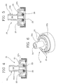
- the automatic valve 21 is therefore a bimetal valve, which has an external body 22 on which the bimetallic strip 23 is placed, housed within a respective annular seat of the external body 22.
- the external body 22 includes a cylindrical portion 22a which can be coupled at an end of the return pipe "R", and an enlarged portion 22b on which the bimetallic strip 23 is applied.
- the cylindrical portion 22a and the enlarged portion 22b are crossed by an inlet channel 24 which exits in correspondence with the bimetallic strip 23.
- the enlarged portion 22b is further crossed by a series of discharge channels 25, which can be placed into a fluid communication with the inlet channel 24, or isolated relative to the inlet channel 24, as a function of a configuration taken by the bimetal valve.
- the bimetallic strip 23 is movable, by deformation, between an opening position ( figure 4 ), in which it allows a fluid communication from the inlet channel 24 to the discharge channels 25, and a closing position ( figure 5 ), in which it obstructs the inlet channel 24 preventing a fluid passage from the inlet channel 24 to the discharge channels 25.
- a sealing 26 is arranged, for improving the seal of the bimetal valve.
- the bimetal valve is arranged within the base body 2.
- the automatic valve could be of a different type, for example the apparatus could include a temperature sensor and/or an electronic thermostat and an electromagnetic valve or pump controlled by the thermostat for opening and closing the passage in correspondence with condensate and steam, respectively.
- the bimetallic strip 23 has the feature of carrying itself in the opening position ( figure 4 ) when into contact with the liquid condensate, then allowing the discharge of the same. On the contrary, the bimetallic strip 23 tends to close itself again ( figure 5 ) when the liquid condensate is discharged and, therefore, when the bimetallic strip 23 directly enters into contact with the steam, avoiding a penalizing undesired exit of the steam, which would further cause a loss of pressure in the apparatus 1.
- the bimetal valve therefore constitutes an automatic valve 21 capable of opening and closing itself as a function, respectively, of the presence of liquid condensate in the return pipe "R" (and in particular close to the bimetal valve itself) and the absence of liquid condensate in the return pipe "R".
- the presence of the spongy body 17 allows to hold the liquid condensate therewith, preventing that, following to the movement of the work body 4, condensate drops, if any, can reach the conduits 19 and be then supplied within the steam from the openings 5.
- this harmful effect is further avoided by the protruding conformation of the conduits 19 within the first chamber 13, which makes the conduits 19 hardly accessible to the liquid condensate existing in the first chamber 13.
- the combined action of the conduits 19 and the spongy body 17 defines an effective separation of the liquid condensate from the steam within the work body 4, with a consequent supply of the sole steam.
- the liquid condensate discharged by the bimetal valve can be advantageously recovered within the base body 2, preferably in correspondence with a container for the condensate collection, which can be operably connected, directly or indirectly through a water tank, to the steam source or boiler for vaporize again the collected condensate.
- the invention is applicable for example to a steam utilizing apparatus, such as a tumble-dryer with a steam cycle.
- the use portion of the steam 5 can consist of a steam utilization chamber within the work body 4 and the collection portion 14 can consist of a steam collection chamber within the work body 4.
- the structure of the separation means can be easier, consisting for example by the only first chamber 13 (whose lower portion can form the collection portion 14) and the conduits 19, without the need of a second chamber 14 and the spongy body 17.
- the present invention attains the proposed aims, overcoming the drawbacks complained in the known art.
- the apparatus according to the invention allows an effective separation of the condensate from the steam directly within the work body, thus allowing that also by shaking in a remarkable way the work body, a liquid exit from the steam supply openings never occurs.
- the apparatus is therefore capable of supplying, under any working conditions, steam free of condensate.
- the work body is very light and easy to handle, being formed by simple and light components.
- the presence of the automatic (bimetal) valve allows a correct removal of the condensate from the work body, without the risk of a steam escape, with a consequent optimization of the effectiveness of the apparatus.
- the invention also results of a simple and economic execution.
Landscapes
- Engineering & Computer Science (AREA)
- Textile Engineering (AREA)
- Health & Medical Sciences (AREA)
- Public Health (AREA)
- Cleaning By Liquid Or Steam (AREA)
- Pipeline Systems (AREA)
- Commercial Cooking Devices (AREA)
Claims (15)
- Dämpfvorrichtung, umfassend einen Arbeitskörper (4), der durch eine Dampfzuleitung (A) mit einer Dampfquelle verbunden werden kann, wobei der Arbeitskörper (4) mindestens einen Abschnitt (5) der Dampfnutzung, mindestens einen Sammelabschnitt (14) sowie Mittel (16, 17, 19) zum Trennen eines flüssigen Kondensats des von der Dampfquelle des Dampfes empfangenen Dampfes umfasst, wobei die Trennmittel (16, 17, 19) zum Befördern des Dampfes in den Abschnitt (5) der Dampfnutzung und des Kondensats in den Sammelabschnitt (14) geeignet sind, wobei die Vorrichtung ferner eine Abflusseinrichtung (R, 21) zum Entfernen des Dampfflüssigkeitskondensats vom Arbeitskörper (4) umfasst, wobei die Abflusseinrichtung (R, 21) eine Rücklaufleitung (R) umfasst, die zum Abführen des Kondensats vom Arbeitskörper (4) mit dem Sammelabschnitt (14) in Fluidverbindung steht,
dadurch gekennzeichnet, dass die Abflusseinrichtung (R, 21) ein selbsttätiges Ventil (21) umfasst, umfassend ein thermisch betätigtes bistabiles Element (23), wobei das selbsttätige Ventil zwischen einer Öffnungsposition, in der es den Abfluss des flüssigen Kondensats zulässt, und einer Schließposition umschaltbar ist. - Vorrichtung nach Anspruch 1, dadurch gekennzeichnet, dass der Arbeitskörper (4) im Abschnitt (5) der Dampfnutzung mindestens eine Dampfzufuhröffnung (5) aufweist.
- Vorrichtung nach den Ansprüchen 1 oder 2, dadurch gekennzeichnet, dass der Arbeitskörper (4) innen eine erste Kammer (13) aufweist, die von einer Wand (12) begrenzt wird und zur Aufnahme des Dampfes geeignet ist, der durch die Dampfzuleitung (A) zugeleitet wird, wobei der Arbeitskörper (4) ferner mindestens ein Rohr (19) umfasst, das sich zwischen der ersten Kammer (13) und dem Abschnitt (5) der Dampfnutzung erstreckt und innen zur ersten Kammer (13) auskragt, um einen Dampfdurchfluss zuzulassen und zumindest einen Durchfluss des Kondensats von der ersten Kammer (13) zum Abschnitt (5) der Dampfnutzung zu reduzieren oder zu verhindern.
- Vorrichtung nach Anspruch 3, dadurch gekennzeichnet, dass der Arbeitskörper (4) innen und in Verbindung mit dem Sammelabschnitt (14) eine zweite Kammer (14) in einer Fluidverbindung mit der ersten Kammer (13) zur Aufnahme des flüssigen Kondensats des Dampfes von der ersten Kammer (13) aufweist,
wobei die zweite Kammer (14) um die erste Kammer (13) herum ausgebildet ist und von der ersten Kammer (13) von der Wand (12) getrennt ist, wobei die Wand (12) perforiert ist, um die Fluidverbindung zwischen der ersten und der zweiten Kammer (13, 14) zuzulassen. - Vorrichtung nach einem oder mehreren der vorangehenden Ansprüche, dadurch gekennzeichnet, dass das Öffnen des selbsttätigen Ventils (21) direkt durch das Vorhandensein einer festgelegten Menge flüssigen Kondensats in Verbindung mit dem selbsttätigen Ventil (21) gesteuert wird und das Schließen durch das Vorhandensein einer festgelegten Dampfmenge innerhalb der Rücklaufleitung (R) gesteuert wird.
- Vorrichtung nach einem der vorangehenden Ansprüche, dadurch gekennzeichnet, dass das thermisch betätigte bistabile Element (23) ein Bimetallstreifen (23) ist.
- Vorrichtung nach einem oder mehreren der vorangehenden Ansprüche, dadurch gekennzeichnet, dass das selbsttätige Ventil (21) an einen Abschnitt der Rücklaufleitung (R) gegenüber dem Arbeitskörper (4) angeschlossen ist.
- Vorrichtung nach einem oder mehreren der vorangehenden Ansprüche, dadurch gekennzeichnet, dass sie die Dampfzuleitung (A) und einen Basiskörper (2) umfasst, der mit dem Arbeitskörper (4) durch die Dampfzuleitung (A) verbunden ist und die Dampfquelle enthält, wobei das selbsttätige Ventil (21) am Basiskörper (2) in Verbindung mit einem Sammelbehälter des Kondensats angeordnet ist.
- Vorrichtung nach Anspruch 8, dadurch gekennzeichnet, dass der Sammelbehälter des Kondensats betriebsbereit direkt oder indirekt mit der Dampfquelle verbunden ist, um das gesammelte Kondensat erneut zu verdampfen.
- Vorrichtung nach einem oder mehreren der vorangehenden Ansprüche, dadurch gekennzeichnet, dass die Trennmittel (17, 19) zum Trennen des Dampfes vom Kondensat durch Gravitation konfiguriert sind.
- Vorrichtung nach einem oder mehreren der vorangehenden Ansprüche, dadurch gekennzeichnet, dass sie die Dampfzuleitung (A) umfasst und dass die Rücklaufleitung (R) und die Dampfzuleitung (A) innerhalb einer einzigen Leitung (3) verkoppelt sind.
- Vorrichtung nach einem oder mehreren der vorangehenden Ansprüche, dadurch gekennzeichnet, dass der Arbeitskörper (4) von einem Bediener an seiner Fläche gegriffen und gehandhabt werden kann, wobei der Arbeitskörper (4) eine Dampfbürste ist.
- Vorrichtung nach Anspruch 1, dadurch gekennzeichnet, dass sie die Dampfzuleitung (A) umfasst und die Trennmittel (17, 19) innerhalb des Arbeitskörpers (4) angeordnet sind und zwischen der Dampfzuleitung (A) und der Dampfzufuhröffnung (5) betriebsbereit sind.
- Vorrichtung nach einem oder mehreren der vorangehenden Ansprüche, dadurch gekennzeichnet, dass die Größe der Öffnungen (5) zur Erzeugung eines festgelegten Dampfgegendrucks innerhalb des Sammelabschnitts (14) kalibriert ist, der zum Drücken des Kondensats durch die Rücklaufleitung "R" geeignet ist.
- Vorrichtung nach einem oder mehreren der vorangehenden Ansprüche, dadurch gekennzeichnet, dass sie die Dampfzuleitung (A) umfasst und der Dampffluss, der von der Dampfzuleitung (A) in den Arbeitskörper (4) eintritt, in eine Richtung ausgerichtet ist, die sich von der Richtung, in die der Abschnitt (5) der Dampfnutzung angeordnet ist, unterscheidet.
Applications Claiming Priority (1)
| Application Number | Priority Date | Filing Date | Title |
|---|---|---|---|
| PCT/IT2008/000400 WO2009153812A1 (en) | 2008-06-17 | 2008-06-17 | Steam utilizing apparatus |
Publications (2)
| Publication Number | Publication Date |
|---|---|
| EP2304094A1 EP2304094A1 (de) | 2011-04-06 |
| EP2304094B1 true EP2304094B1 (de) | 2011-10-12 |
Family
ID=40433637
Family Applications (1)
| Application Number | Title | Priority Date | Filing Date |
|---|---|---|---|
| EP08789989A Not-in-force EP2304094B1 (de) | 2008-06-17 | 2008-06-17 | Dämpfvorrichtung |
Country Status (3)
| Country | Link |
|---|---|
| EP (1) | EP2304094B1 (de) |
| AT (1) | ATE528436T1 (de) |
| WO (1) | WO2009153812A1 (de) |
Families Citing this family (1)
| Publication number | Priority date | Publication date | Assignee | Title |
|---|---|---|---|---|
| CN102995376A (zh) * | 2012-10-18 | 2013-03-27 | 吴江市元通纺织品有限公司 | 一种无渗漏熨烫机 |
Family Cites Families (4)
| Publication number | Priority date | Publication date | Assignee | Title |
|---|---|---|---|---|
| GB588152A (en) * | 1944-11-15 | 1947-05-15 | Asher Joseph Simons | Improvements in and relating to a combination steam ironing unit |
| US3263350A (en) * | 1958-12-18 | 1966-08-02 | Abraham Carlos Salomon | Electric steam iron |
| GB877444A (en) * | 1959-07-04 | 1961-09-13 | Braithwaite I & Son Eng Ltd | Improvements in pressing irons |
| DE2829659A1 (de) * | 1978-07-06 | 1980-01-10 | Wilhelm Heinrichs | Vorrichtung zur verhinderung von kondenswasserbildung in einem elektrisch beheizten dampfbuegeleisen |
-
2008
- 2008-06-17 WO PCT/IT2008/000400 patent/WO2009153812A1/en not_active Ceased
- 2008-06-17 EP EP08789989A patent/EP2304094B1/de not_active Not-in-force
- 2008-06-17 AT AT08789989T patent/ATE528436T1/de not_active IP Right Cessation
Also Published As
| Publication number | Publication date |
|---|---|
| WO2009153812A1 (en) | 2009-12-23 |
| EP2304094A1 (de) | 2011-04-06 |
| ATE528436T1 (de) | 2011-10-15 |
Similar Documents
| Publication | Publication Date | Title |
|---|---|---|
| EP1441059B1 (de) | Verfahren zur Behandlung von Textilien in einem Haushaltswäschetrockner | |
| EP2735635B1 (de) | Waschmaschine und verfahren zum zuführen von waschwasser für eine waschmaschine | |
| EP1861540B1 (de) | Wäschebehandlungsmaschine | |
| AU2013222057B2 (en) | Laundry treatment method and apparatus | |
| EP1863967B1 (de) | Waschmaschine | |
| EP2391763B1 (de) | Kleidertrockner mit schubladenartiger benebelungsvorrichtung | |
| CN107429475B (zh) | 具有水垢收集室的手持式蒸汽挂烫机 | |
| EP1568814B1 (de) | Waschmittel-Einspülvorrichtung für eine Waschmaschine | |
| US9493904B2 (en) | Laundry treatment device having a steam generator and method for treating items to be washed | |
| EP2703542B1 (de) | Dampfsprühvorrichtung und Wäschetrockner damit | |
| EP1914337B1 (de) | Waschvorrichtung mit Biopräventionszyklus | |
| EP2061923B1 (de) | Waschmaschine | |
| EP2467529B1 (de) | Wäschebehandlungsgerät mit einer Dampfeindüsvorrichtung | |
| EP2290149B1 (de) | Düse und Versorgungssystem eines Zusatzmittlels für eine Vorrichtung zum Behandeln von Textilien | |
| EP2873722B1 (de) | Verfahren zur Behandlung von Wäsche und darin verwendetes Reinigungsmittel | |
| EP2295628B1 (de) | Verfahren zur Behandlung von Wäsche in einer Haushaltsmaschine, sowie Haushaltsmaschine, insbesondere Haushaltswäschetrockner | |
| EP1887127B1 (de) | Wäschebehandlungsmaschine | |
| US7191554B2 (en) | Steam iron | |
| EP4025736B1 (de) | Bügelsohle für dampfbügeleisen und verwandte herstellungsverfahren | |
| US20190234001A1 (en) | Dispensing system for a laundry treating appliance | |
| CN106222976B (zh) | 衣物处理装置 | |
| EP2304094A1 (de) | Dämpfvorrichtung | |
| EP2860298B1 (de) | Vorrichtung zur behandlung von kleidungsstücken | |
| KR102141562B1 (ko) | 스팀생성기를 구비한 의류처리장치 | |
| WO2011020708A1 (en) | Steam injection arrangement for a laundry appliance, and laundry appliance |
Legal Events
| Date | Code | Title | Description |
|---|---|---|---|
| PUAI | Public reference made under article 153(3) epc to a published international application that has entered the european phase |
Free format text: ORIGINAL CODE: 0009012 |
|
| 17P | Request for examination filed |
Effective date: 20101129 |
|
| AK | Designated contracting states |
Kind code of ref document: A1 Designated state(s): AT BE BG CH CY CZ DE DK EE ES FI FR GB GR HR HU IE IS IT LI LT LU LV MC MT NL NO PL PT RO SE SI SK TR |
|
| AX | Request for extension of the european patent |
Extension state: AL BA MK RS |
|
| GRAP | Despatch of communication of intention to grant a patent |
Free format text: ORIGINAL CODE: EPIDOSNIGR1 |
|
| GRAS | Grant fee paid |
Free format text: ORIGINAL CODE: EPIDOSNIGR3 |
|
| GRAA | (expected) grant |
Free format text: ORIGINAL CODE: 0009210 |
|
| DAX | Request for extension of the european patent (deleted) | ||
| AK | Designated contracting states |
Kind code of ref document: B1 Designated state(s): AT BE BG CH CY CZ DE DK EE ES FI FR GB GR HR HU IE IS IT LI LT LU LV MC MT NL NO PL PT RO SE SI SK TR |
|
| REG | Reference to a national code |
Ref country code: GB Ref legal event code: FG4D |
|
| REG | Reference to a national code |
Ref country code: CH Ref legal event code: EP |
|
| REG | Reference to a national code |
Ref country code: IE Ref legal event code: FG4D |
|
| REG | Reference to a national code |
Ref country code: CH Ref legal event code: NV Representative=s name: BUGNION S.A. |
|
| REG | Reference to a national code |
Ref country code: DE Ref legal event code: R096 Ref document number: 602008010459 Country of ref document: DE Effective date: 20111208 |
|
| REG | Reference to a national code |
Ref country code: NL Ref legal event code: VDEP Effective date: 20111012 |
|
| LTIE | Lt: invalidation of european patent or patent extension |
Effective date: 20111012 |
|
| REG | Reference to a national code |
Ref country code: AT Ref legal event code: MK05 Ref document number: 528436 Country of ref document: AT Kind code of ref document: T Effective date: 20111012 |
|
| PG25 | Lapsed in a contracting state [announced via postgrant information from national office to epo] |
Ref country code: IS Free format text: LAPSE BECAUSE OF FAILURE TO SUBMIT A TRANSLATION OF THE DESCRIPTION OR TO PAY THE FEE WITHIN THE PRESCRIBED TIME-LIMIT Effective date: 20120212 Ref country code: NO Free format text: LAPSE BECAUSE OF FAILURE TO SUBMIT A TRANSLATION OF THE DESCRIPTION OR TO PAY THE FEE WITHIN THE PRESCRIBED TIME-LIMIT Effective date: 20120112 Ref country code: LT Free format text: LAPSE BECAUSE OF FAILURE TO SUBMIT A TRANSLATION OF THE DESCRIPTION OR TO PAY THE FEE WITHIN THE PRESCRIBED TIME-LIMIT Effective date: 20111012 Ref country code: BE Free format text: LAPSE BECAUSE OF FAILURE TO SUBMIT A TRANSLATION OF THE DESCRIPTION OR TO PAY THE FEE WITHIN THE PRESCRIBED TIME-LIMIT Effective date: 20111012 |
|
| PG25 | Lapsed in a contracting state [announced via postgrant information from national office to epo] |
Ref country code: PT Free format text: LAPSE BECAUSE OF FAILURE TO SUBMIT A TRANSLATION OF THE DESCRIPTION OR TO PAY THE FEE WITHIN THE PRESCRIBED TIME-LIMIT Effective date: 20120213 Ref country code: GR Free format text: LAPSE BECAUSE OF FAILURE TO SUBMIT A TRANSLATION OF THE DESCRIPTION OR TO PAY THE FEE WITHIN THE PRESCRIBED TIME-LIMIT Effective date: 20120113 Ref country code: LV Free format text: LAPSE BECAUSE OF FAILURE TO SUBMIT A TRANSLATION OF THE DESCRIPTION OR TO PAY THE FEE WITHIN THE PRESCRIBED TIME-LIMIT Effective date: 20111012 Ref country code: SE Free format text: LAPSE BECAUSE OF FAILURE TO SUBMIT A TRANSLATION OF THE DESCRIPTION OR TO PAY THE FEE WITHIN THE PRESCRIBED TIME-LIMIT Effective date: 20111012 Ref country code: HR Free format text: LAPSE BECAUSE OF FAILURE TO SUBMIT A TRANSLATION OF THE DESCRIPTION OR TO PAY THE FEE WITHIN THE PRESCRIBED TIME-LIMIT Effective date: 20111012 Ref country code: SI Free format text: LAPSE BECAUSE OF FAILURE TO SUBMIT A TRANSLATION OF THE DESCRIPTION OR TO PAY THE FEE WITHIN THE PRESCRIBED TIME-LIMIT Effective date: 20111012 Ref country code: NL Free format text: LAPSE BECAUSE OF FAILURE TO SUBMIT A TRANSLATION OF THE DESCRIPTION OR TO PAY THE FEE WITHIN THE PRESCRIBED TIME-LIMIT Effective date: 20111012 |
|
| PG25 | Lapsed in a contracting state [announced via postgrant information from national office to epo] |
Ref country code: CY Free format text: LAPSE BECAUSE OF FAILURE TO SUBMIT A TRANSLATION OF THE DESCRIPTION OR TO PAY THE FEE WITHIN THE PRESCRIBED TIME-LIMIT Effective date: 20111012 |
|
| PG25 | Lapsed in a contracting state [announced via postgrant information from national office to epo] |
Ref country code: DK Free format text: LAPSE BECAUSE OF FAILURE TO SUBMIT A TRANSLATION OF THE DESCRIPTION OR TO PAY THE FEE WITHIN THE PRESCRIBED TIME-LIMIT Effective date: 20111012 Ref country code: EE Free format text: LAPSE BECAUSE OF FAILURE TO SUBMIT A TRANSLATION OF THE DESCRIPTION OR TO PAY THE FEE WITHIN THE PRESCRIBED TIME-LIMIT Effective date: 20111012 Ref country code: BG Free format text: LAPSE BECAUSE OF FAILURE TO SUBMIT A TRANSLATION OF THE DESCRIPTION OR TO PAY THE FEE WITHIN THE PRESCRIBED TIME-LIMIT Effective date: 20120112 Ref country code: CZ Free format text: LAPSE BECAUSE OF FAILURE TO SUBMIT A TRANSLATION OF THE DESCRIPTION OR TO PAY THE FEE WITHIN THE PRESCRIBED TIME-LIMIT Effective date: 20111012 Ref country code: SK Free format text: LAPSE BECAUSE OF FAILURE TO SUBMIT A TRANSLATION OF THE DESCRIPTION OR TO PAY THE FEE WITHIN THE PRESCRIBED TIME-LIMIT Effective date: 20111012 |
|
| PLBE | No opposition filed within time limit |
Free format text: ORIGINAL CODE: 0009261 |
|
| STAA | Information on the status of an ep patent application or granted ep patent |
Free format text: STATUS: NO OPPOSITION FILED WITHIN TIME LIMIT |
|
| PG25 | Lapsed in a contracting state [announced via postgrant information from national office to epo] |
Ref country code: PL Free format text: LAPSE BECAUSE OF FAILURE TO SUBMIT A TRANSLATION OF THE DESCRIPTION OR TO PAY THE FEE WITHIN THE PRESCRIBED TIME-LIMIT Effective date: 20111012 Ref country code: RO Free format text: LAPSE BECAUSE OF FAILURE TO SUBMIT A TRANSLATION OF THE DESCRIPTION OR TO PAY THE FEE WITHIN THE PRESCRIBED TIME-LIMIT Effective date: 20111012 |
|
| 26N | No opposition filed |
Effective date: 20120713 |
|
| REG | Reference to a national code |
Ref country code: DE Ref legal event code: R097 Ref document number: 602008010459 Country of ref document: DE Effective date: 20120713 |
|
| PG25 | Lapsed in a contracting state [announced via postgrant information from national office to epo] |
Ref country code: AT Free format text: LAPSE BECAUSE OF FAILURE TO SUBMIT A TRANSLATION OF THE DESCRIPTION OR TO PAY THE FEE WITHIN THE PRESCRIBED TIME-LIMIT Effective date: 20111012 Ref country code: MC Free format text: LAPSE BECAUSE OF NON-PAYMENT OF DUE FEES Effective date: 20120630 |
|
| REG | Reference to a national code |
Ref country code: IE Ref legal event code: MM4A |
|
| PG25 | Lapsed in a contracting state [announced via postgrant information from national office to epo] |
Ref country code: IE Free format text: LAPSE BECAUSE OF NON-PAYMENT OF DUE FEES Effective date: 20120617 Ref country code: ES Free format text: LAPSE BECAUSE OF FAILURE TO SUBMIT A TRANSLATION OF THE DESCRIPTION OR TO PAY THE FEE WITHIN THE PRESCRIBED TIME-LIMIT Effective date: 20120123 |
|
| PG25 | Lapsed in a contracting state [announced via postgrant information from national office to epo] |
Ref country code: FI Free format text: LAPSE BECAUSE OF FAILURE TO SUBMIT A TRANSLATION OF THE DESCRIPTION OR TO PAY THE FEE WITHIN THE PRESCRIBED TIME-LIMIT Effective date: 20111012 |
|
| PG25 | Lapsed in a contracting state [announced via postgrant information from national office to epo] |
Ref country code: MT Free format text: LAPSE BECAUSE OF FAILURE TO SUBMIT A TRANSLATION OF THE DESCRIPTION OR TO PAY THE FEE WITHIN THE PRESCRIBED TIME-LIMIT Effective date: 20111012 |
|
| PG25 | Lapsed in a contracting state [announced via postgrant information from national office to epo] |
Ref country code: TR Free format text: LAPSE BECAUSE OF FAILURE TO SUBMIT A TRANSLATION OF THE DESCRIPTION OR TO PAY THE FEE WITHIN THE PRESCRIBED TIME-LIMIT Effective date: 20111012 |
|
| PG25 | Lapsed in a contracting state [announced via postgrant information from national office to epo] |
Ref country code: LU Free format text: LAPSE BECAUSE OF NON-PAYMENT OF DUE FEES Effective date: 20120617 |
|
| PG25 | Lapsed in a contracting state [announced via postgrant information from national office to epo] |
Ref country code: HU Free format text: LAPSE BECAUSE OF FAILURE TO SUBMIT A TRANSLATION OF THE DESCRIPTION OR TO PAY THE FEE WITHIN THE PRESCRIBED TIME-LIMIT Effective date: 20080617 |
|
| REG | Reference to a national code |
Ref country code: FR Ref legal event code: PLFP Year of fee payment: 9 |
|
| REG | Reference to a national code |
Ref country code: DE Country of ref document: DE Ref legal event code: R082 Ref document number: 602008010459 Representative=s name: BETTEN & RESCH PATENT- UND RECHTSANWAELTE PART, DE Ref country code: DE Ref legal event code: R081 Ref document number: 602008010459 Country of ref document: DE Owner name: CANDY HOOVER GROUP S.R.L., BRUGHERIO, IT Free format text: FORMER OWNER: DIERRE FINANZIARIA S.P.A., CASTENEDOLO, BRESCIA, IT |
|
| REG | Reference to a national code |
Ref country code: DE Ref legal event code: R082 Ref document number: 602008010459 Country of ref document: DE |
|
| REG | Reference to a national code |
Ref country code: GB Ref legal event code: 732E Free format text: REGISTERED BETWEEN 20170216 AND 20170222 |
|
| REG | Reference to a national code |
Ref country code: FR Ref legal event code: PLFP Year of fee payment: 10 |
|
| REG | Reference to a national code |
Ref country code: FR Ref legal event code: TP Owner name: CANDY HOOVER GROUP S.R.L., IT Effective date: 20170808 |
|
| REG | Reference to a national code |
Ref country code: CH Ref legal event code: PUE Owner name: CANDY HOOVER GROUP S.R.L., IT Free format text: FORMER OWNER: DIERRE FINANZIARIA S.P.A., IT |
|
| REG | Reference to a national code |
Ref country code: FR Ref legal event code: PLFP Year of fee payment: 11 |
|
| PGFP | Annual fee paid to national office [announced via postgrant information from national office to epo] |
Ref country code: CH Payment date: 20190619 Year of fee payment: 12 |
|
| PGFP | Annual fee paid to national office [announced via postgrant information from national office to epo] |
Ref country code: FR Payment date: 20200630 Year of fee payment: 13 |
|
| PGFP | Annual fee paid to national office [announced via postgrant information from national office to epo] |
Ref country code: IT Payment date: 20200609 Year of fee payment: 13 Ref country code: GB Payment date: 20200625 Year of fee payment: 13 |
|
| PGFP | Annual fee paid to national office [announced via postgrant information from national office to epo] |
Ref country code: DE Payment date: 20200630 Year of fee payment: 13 |
|
| REG | Reference to a national code |
Ref country code: CH Ref legal event code: PL |
|
| PG25 | Lapsed in a contracting state [announced via postgrant information from national office to epo] |
Ref country code: LI Free format text: LAPSE BECAUSE OF NON-PAYMENT OF DUE FEES Effective date: 20200630 Ref country code: CH Free format text: LAPSE BECAUSE OF NON-PAYMENT OF DUE FEES Effective date: 20200630 |
|
| REG | Reference to a national code |
Ref country code: DE Ref legal event code: R119 Ref document number: 602008010459 Country of ref document: DE |
|
| GBPC | Gb: european patent ceased through non-payment of renewal fee |
Effective date: 20210617 |
|
| PG25 | Lapsed in a contracting state [announced via postgrant information from national office to epo] |
Ref country code: GB Free format text: LAPSE BECAUSE OF NON-PAYMENT OF DUE FEES Effective date: 20210617 Ref country code: DE Free format text: LAPSE BECAUSE OF NON-PAYMENT OF DUE FEES Effective date: 20220101 |
|
| PG25 | Lapsed in a contracting state [announced via postgrant information from national office to epo] |
Ref country code: FR Free format text: LAPSE BECAUSE OF NON-PAYMENT OF DUE FEES Effective date: 20210630 |
|
| PG25 | Lapsed in a contracting state [announced via postgrant information from national office to epo] |
Ref country code: IT Free format text: LAPSE BECAUSE OF NON-PAYMENT OF DUE FEES Effective date: 20210617 |