EP2304123B1 - Système modulaire pour structure de façade - Google Patents
Système modulaire pour structure de façade Download PDFInfo
- Publication number
- EP2304123B1 EP2304123B1 EP09776872.5A EP09776872A EP2304123B1 EP 2304123 B1 EP2304123 B1 EP 2304123B1 EP 09776872 A EP09776872 A EP 09776872A EP 2304123 B1 EP2304123 B1 EP 2304123B1
- Authority
- EP
- European Patent Office
- Prior art keywords
- panels
- panel
- upstanding
- flanges
- intermediate portion
- Prior art date
- Legal status (The legal status is an assumption and is not a legal conclusion. Google has not performed a legal analysis and makes no representation as to the accuracy of the status listed.)
- Active
Links
Images




Classifications
-
- E—FIXED CONSTRUCTIONS
- E04—BUILDING
- E04F—FINISHING WORK ON BUILDINGS, e.g. STAIRS, FLOORS
- E04F13/00—Coverings or linings, e.g. for walls or ceilings
- E04F13/07—Coverings or linings, e.g. for walls or ceilings composed of covering or lining elements; Sub-structures therefor; Fastening means therefor
- E04F13/08—Coverings or linings, e.g. for walls or ceilings composed of covering or lining elements; Sub-structures therefor; Fastening means therefor composed of a plurality of similar covering or lining elements
- E04F13/0801—Separate fastening elements
- E04F13/0803—Separate fastening elements with load-supporting elongated furring elements between wall and covering elements
- E04F13/081—Separate fastening elements with load-supporting elongated furring elements between wall and covering elements with additional fastening elements between furring elements and covering elements
- E04F13/0812—Separate fastening elements with load-supporting elongated furring elements between wall and covering elements with additional fastening elements between furring elements and covering elements fixed by means of spring action
-
- E—FIXED CONSTRUCTIONS
- E04—BUILDING
- E04F—FINISHING WORK ON BUILDINGS, e.g. STAIRS, FLOORS
- E04F13/00—Coverings or linings, e.g. for walls or ceilings
- E04F13/07—Coverings or linings, e.g. for walls or ceilings composed of covering or lining elements; Sub-structures therefor; Fastening means therefor
- E04F13/08—Coverings or linings, e.g. for walls or ceilings composed of covering or lining elements; Sub-structures therefor; Fastening means therefor composed of a plurality of similar covering or lining elements
- E04F13/12—Coverings or linings, e.g. for walls or ceilings composed of covering or lining elements; Sub-structures therefor; Fastening means therefor composed of a plurality of similar covering or lining elements of metal or with an outer layer of metal or enameled metal
Definitions
- the present invention relates to a modular system for a façade structure for a building comprising panels and panel retaining elements for mounting the panels to the building.
- the invention also relates to a façade structure made using said modular system.
- BE900278 discloses an example of such a clamp for mounting panels to a wall or ceiling.
- the interlock is frequently achieved by using the male and female principle.
- WO00/23672 shows examples of covering systems utilising this male and female interlock.
- the construction of such buildings usually starts with erecting a framework comprising building elements to which the metal panels, for instance for the roof or façade, are attached.
- the interlocking system requires starting the attachment of the panels at a lower level and working upwards or the other way around. In all cases the next panel firmly locks the preceding panel in place.
- a disadvantage of the application of said panels is that when an intermediate panel needs to be replaced, for instance when it is damaged, these panels can only be replaced without destroying the panel by removing the other panels which were installed after the damaged panel are removed as well.
- the alternative of cutting the intermediate damaged panel and/or destroying the points of suspension of the damaged panel allows the panel to be removed without the need to remove other panels. Afterwards, the points of suspension need to be repaired. This is a difficult and time-consuming operation.
- a modular system for a façade structure for a building comprising panels and panel retaining elements for mounting the panels to the building
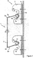
- said panels 1 comprise an intermediate portion 2 extending between two upstanding flanges 3a,3b located on opposite edges 2a,2b of the intermediate portion 2 and wherein the free ends 4a,4b of the upstanding flanges 3a,3b are bent so as to extend towards the back side 2f of the intermediate portion of the panel 1 thereby forming substantially v- or u-shaped flanges and wherein the free ends 4a,4b of the bent upstanding flanged do not touch the back side 2f of the intermediate portion 2, and wherein said panel retaining elements 5 comprise a base portion 6 for securing the retaining element to the building and at least one upstanding flange 7, wherein the upstanding flange 7 is provided with recesses 8a,8b, and which recesses are provided with securing notches 9a,9b so as allow mounting the panels to the
- the mounting of the panels preferably occurs by hanging the upper upstanding flange part of a panel in the recesses 8b, allowing it to hang onto the securing notch 9b, and then clicking the lower upstanding flange into the recess 8a, allowing it to be secured by the securing notch 9a.
- the panels may be mounted by pressing the two upstanding flanges of one panel into the recesses and behind securing notches simultaneously. It is important to note that there is no need to mount two adjoining panels simultaneously by clicking the flanges of the two adjoining panels into the recesses of a mounting bracket simultaneously. The clicking in place of the flange of one panel into the recess of a mounting bracket can be done before the hanging in place of the adjoining panel in the other recess of said mounting bracket.
- the flexing of the intermediate portion and the elastic resistance of the flanges will exert an inwardly directed force which will allow in the bent-away free ends of the upstanding flanges on the panel as one-way beards which are initially pressed in the recesses of the retaining element, and the spring-back of the flanges will ensure that the free edges hook behind the securing notches in the retaining elements.
- the deformation of the upstanding flanges during mounting is preferably an elastic deformation only.
- the intermediate portion of the panel is preferably rectangular in shape, because this way the panels are cheapest and more or less interchangeable.
- the opposite edges 2a,2b of the intermediate portion of adjoining panels abut, so as to achieve a snug fit between two adjoining panels.
- the opposite edges with the upstanding flanges are defined to be in the width direction of the panel, whereas the distance between the two upstanding flanges on one panel is defined as the height direction of the panel.
- the recesses may have a substantially complementary shape to the shape of the substantially v- or u-shaped flanges of the panels.
- the securing notches are elongated so as to create a slot-shaped or slit-shaped recess to receive the free ends of the upstanding flanges.
- the free ends of the upstanding flanges abut the securing notches of the recesses in the retaining elements head-on, i.e. the extremity of the free end touches the securing notch when a pulling force is exerted on the panel.
- the recesses are slot- or slit-shaped as a result of the elongation of the securing notches.
- the panels may comprise a perforated or mesh portion in the intermediate portion.
- the intermediate portion is preferably flat to produce a smooth façade, it is also possible to provide the intermediate portion with beads, stiffening ribs, micro lines or ridges. This may have a technical reason, e.g. to increase stiffness of the panel, or an aesthetical reason.
- the angle between one of the upstanding flanges and the intermediate portion of the panels is smaller than 90°.
- the panels are mounted on a vertical or tilted surface (i.e. non-horizontal), the panels are mounted such that the angle between the bottom flange and the intermediate portion is the acute angle, and the angle between the top flange and the intermediate portion is the obtuse angle.
- the angle between one of the upstanding flanges and the intermediate portion of the panels is larger than 90°.
- the angle between one of the upstanding flanges and the intermediate portion of the panels is smaller than 90° and the angle between the other upstanding flange and the intermediate portion of the panel is larger than 90°.
- one, more or all of the retaining element 5 comprise two upstanding flanges 7a,7b, wherein both upstanding flanges are provided with recesses 8a,8b which are substantially complementary to the shape of the substantially v- or u-shaped flanges of the panel 1, and which recesses 8a,8b are provided with securing notches 9a,9b .
- This embodiment allows an even more secure mounting of the panel into the retaining element by using both upstanding flanges of the retaining element to hold the upstanding flange of one panel, or it allows two neighbouring panels to be mounted, one using the one upstanding flange of the retaining element, and the neighbouring panel in the other upstanding flange.
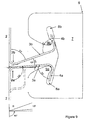
- the upstanding flanges 3a,3b of the panels are not perpendicular to the intermediate portion 2 when the panel is seen in cross section along a line perpendicular to the edges 2a,2b, but wherein the angle formed by the intermediate portion and the first upstanding flange 36 is ⁇ °, and the angle formed by the intermediate portion and the second upstanding flange 3a is (180-(alpha + beta))°.
- the tilted upstanding flanges result in a tilted gap between two adjoining panels, particularly when mounted vertically, which prevents our counteracts water to seep through the gap towards the building or the support structure.
- the angle between the two adjoining flanges, ⁇ is 0 in this case.
- the angle a is sharp, i.e. less than 90° to avoid water permeating through the gap between two adjoining upstanding flanges of two adjoining panels.
- this embodiment will also comprise panels wherein ⁇ is not 0.
- This widening gap effectively counteracts the capillary effect that such a gap may have, and penetration of moisture through the gap is reduced or prevented.
- the preferably downward sloping of the gap as illustrated in figure 3 counteracts penetration of moisture as well as the penetration of wind driven rain. Since the sharp angle between the intermediate portion 2 and 3b of one panel is defined as a, the obtuse angle between intermediate portion 2 and 3a of the adjoining panel is 180-( ⁇ + ⁇ ).
- ⁇ is larger than 5° because it allows quick and precise mounting of the panels. It was found that ⁇ is preferably larger than 5°. It is preferable that the angle is not larger than 25°. In a preferred embodiment the angle is between 10 and 20°, e.g. 15°.
- the panels are made from sheet material of steel, a steel alloy, aluminium or an aluminium alloy, preferably by roll-forming, and wherein the panels are optionally coated with coating layers providing the panels with corrosion protection and/or colour and/or texture.
- a suitable thickness of the panels is between 0.5 and 2.5 mm, e.g. about 1 mm.
- the panels may be produced by simple bending or press-braking, but preferably by roll-forming.
- a dedicated roll-former By using a dedicated roll-former, the panels can be produced on the erection site of a building. Such a dedicated roll-former may be transported to the erection site in a standard transport- or sea-container
- a plurality of panel retaining elements is mounted onto the building and adjoining panels are snapped into the recesses 8a,8b of the retaining elements and wherein the upstanding flange 3a of a first panel and the upstanding flange 3b of a second panel longitudinally adjoin so as to allow mounting the adjoining panels to the building by snapping the adjoining v- or u-shaped flanges of the panels into the corresponding recesses 8a,8b in the upstanding flanges 7 of one or more retaining elements 5.
- Longitudinal adjoining means that the edge 2a of one panel adjoins the edge 2b of the adjoining panel.
- the panel retaining elements may be mounted to the building individually as single brackets, or as a part of a rail comprising a plurality of brackets over the length of the rail.
- the plurality of brackets over the length of the rail may be individually premounted single brackets, or the rail may be provided with recesses to receive and hold the upstanding flanges of the panels (item 5 in Figure 11a ).
- the single brackets or the rail comprising the plurality of brackets are mounted to the building using a further U-shaped bracket (item 13 in Figure 11 ) which allow for some translational tolerance during mounting of the rails or brackets to the building, thereby facilitating alignment of the rails or brackets, preferably wherein the legs of the U-shaped bracket are provided with notches which allow the U-shaped bracket to take up some rotational tolerance during mounting of the rails or brackets to the building.
- the gap between two adjoining panels is identical over the entire length of the two adjoining panels, thereby achieving a nice (i.e. aesthetically pleasing) finish of the façade.
- the recess is identical over the entire length of the two adjoining panel. The presence of such a gap allows for thermal expansion of the panel without the risk of buckling the flat part of the panel. It also allows for ventilation and a degree of pressure equalisation between the front and back sides of the panel when subjected to dynamic wind loads, and thereby reduces wind-suction effects.
- a plurality of panel retaining elements is mounted onto the building and wherein the upstanding flanges 3a,3b of a first panel are snapped into the recesses 8a,8b of one upstanding flange of a retaining element and wherein the upstanding flanges 3a,3b of a neighbouring panel are snapped into the recesses 8a,8b of the other upstanding flange of the retaining element preferably wherein the gap between the two neighbouring panels is minimised by abutting the edge 2c of the intermediate portion of the first panel against the edge 2d of the intermediate portion of the neighbouring panel.
- an intermediate material is provided between the upstanding flanges and the panel retaining element when mounted.
- This intermediate material may prevents the occurrence of rattling as a result of metal-metal contact, for instance in windy circumstances.
- This intermediate material may be in the form of a layer or material, or a loose inlay which e.g. is put in place in the recesses of the clip prior to clicking the panel in place, or an inlay which is clipped into or onto the recesses of the clip prior to clicking the panel in place.
- the material may be a polymer material, such as a plastic or a rubber-like material.
- the intermediate material may also be used to improve an reduced friction of the panels during mounting, or to correct minor size deviations (tolerance).
- some panel retaining elements could be used as fixed points (by using high friction material) whereas other retaining elements could allow some movement to allow the thermal expansion of the panels (by using very low friction material).
- the intermediate material may also be provided with beards or spring elements so as to allow easy insertion of the panel in one direction during mounting the panel and difficult extraction in the opposite direction, thereby adding to the gripping power of the retaining element on the flanges of the panel when a pulling force is exerted on the panel.
- the panels may also be provided with an upstanding flange at one or both of the edges 2c and/or 2d.
- This upstanding flange may serve to create an aesthetic or safety enhancing effect when the panel is mounted as the last panel near the edge of the façade.
- This upstanding flange would preferably be bent in the same direction as the upstanding flanges which are clipped into the panel retaining elements. It is preferable that this upstanding flange is provided to the panel on the building site. This has the advantage that the width of the panel can be fine-tuned on site by cutting the panel to the correct width followed by bending the edge. To enable a nice finish of the panel, the corners of the panel need to be cut out prior to bending the flange to avoid creases in the panel.
- the modular system according to the invention would also be suitable for producing a roof structure.
- the roof would not be impermeable to water at the locations where the panels abut, it is used as an over-cladding, e.g. over a standing seam roof which is waterproof, where the standing seams can be used to fix the panel retaining elements to.
- Additional precautions to make the roof impermeable to water at the location of the where panels adjoining by sealing the gaps between adjoining and/or neighbouring panels e.g. by using a sealant, or waterproof inlays or rubberlike profiles have proven not to provide a long term waterproofing.
- Use of the modular system for producing a ceiling structure i.e. indoors) is also possible.
- the combination of such a ceiling for instance with perforated or mesh intermediate portions in the panels, with sound-proofing material behind the intermediate portion provides an acoustic ceiling. Heating or cooling elements may also be mounted behind the perforated panels.
- a method of assembling a façade structure on a building using a plurality of panels I members and panel retaining elements 5 for mounting the panels to the building wherein said panels 1 comprise an intermediate portion 2 extending between two upstanding flanges 3a,3b located on opposite edges 2a,2b of the intermediate portion 2 and wherein the free ends 4a,4b of the upstanding flanges 3a,3b are bent so as to extend towards the back side 2f of the intermediate portion of the panel 1 thereby forming substantially v- or u-shaped flanges and wherein the free ends 4a,4b of the bent upstanding flanged do not touch the back side 2f of the intermediate portion 2, and wherein said panel retaining elements 5 comprise a base portion 6 for securing the retaining element to the building and at least one upstanding flange 7, wherein the upstanding flange 7 is provided with recesses 8a,8b which have a substantially complementary shape to the shape of the substantially v- or u
- the mounting of the panels preferably occurs by hanging the upper upstanding flange part of a panel in the recesses 8b, allowing it to hang onto the securing notch 9b, and then clicking the lower upstanding flange into the recess 8a, allowing it to be secured by the securing notch 9a.
- the panels may be mounted by pressing the two upstanding flanges into the recesses and behind securing notches simultaneously.
- the mounting may start at the bottom of the façade and move upwards, or start at the top of the façade and move downwards, or the mounting may start at any chosen place of the building and move upwards and downwards. It is even possible to leave out panels during construction, only to fill the gaps later. This may be extremely helpful when during building a scaffolding is used. For safety reasons, such a scaffolding needs to be secured to the building. By securing the scaffolding to the building at the locations where the panels are not yet mounted the securing points can later be covered by a panel when the scaffolding is removed.
- the clicking into place and the self-securing behind the securing notches of the panel retaining elements means that the panels can be very easily and quickly mounted by a simple pressing and snapping into place, even in between panels already mounted.
- the deformation of the upstanding flanges during mounting is preferably an elastic deformation only.
- the fact that the order of mounting the panels is irrelevant is also important when mounting coloured panels. Minimal differences in colour or texture of subsequent batches of material from which the panels are produced, e.g. by roll forming, become visible when consecutively mounting all panels of one coil and then all panels of another batch.
- the method according to the invention allows mounting the panels scattered over the façade and filling the gaps scattered with the panels of any following bath. The scattering eliminates any differences in texture or colour.
- the method involves using one, more or all retaining elements wherein the retaining elements comprise two upstanding flanges 7a,7b, wherein both upstanding flanges are provided with recesses 8a,8b which are substantially complementary to the shape of the substantially v- or u-shaped flanges of the panel 1, and which recesses 8a, 8b are provided with securing notches 9a,9b .
- This embodiment allows an even more secure mounting of the panel into the retaining element by using both upstanding flanges of the retaining element to hold the upstanding flange of one panel, or it allows two neighbouring panels to be mounted, one using the one upstanding flange of the retaining element, and the neighbouring panel in the other upstanding flange.
- the method of assembling a façade involves mounting consecutive panels in such a manner that the gap between the two neighbouring panels is minimised by abutting the edge 2c of the intermediate portion of the first panel against the edge 2d of the intermediate portion of the neighbouring panel. In this embodiment, there is no gap between two neighbouring panels, thereby achieving a smooth finish of the façade.
- the method uses panels with upstanding flanges of the panels which are not perpendicular to the intermediate portion when the panel is seen in cross section along a line perpendicular to the edges, but wherein the angle formed by the intermediate portion and the first upstanding flange is ⁇ °, and the angle formed by the intermediate portion and the second upstanding flange is (180 - (alpha + beta))°.
- the tilted upstanding flanges result in a tilted gap between two adjoining panels, particularly when mounted vertically, which prevents our counteracts water to seep through the gap towards the building or the support structure.
- Another advantage of using the tilted flanges is that the panels can not be inadvertently mounted upside down. Particularly when using coloured or textured panels this avoids apparent colour differences because all panels are mounted in the same direction.
- a method of repairing the façade structure comprising the steps of removing the damaged panel or damaged panels individually, for instance by cutting the member so as to enable removal of the panel without damaging the panel retaining elements holding the damaged panel, followed by replacing the removed panel by snapping a replacement panel in place. Due to the absence of the male-female interlocking, only the damaged panels need to be removed. By removing the damaged panel(s) without damage to the retaining elements, replacement panel of the correct size can be easily and quickly snapped in place. This repair option is very important in locations where damage to the panel can occur for instance by accidents or vandalism such as scratching, graffiti or even shooting using firearms.
Landscapes
- Engineering & Computer Science (AREA)
- Architecture (AREA)
- Civil Engineering (AREA)
- Structural Engineering (AREA)
- Finishing Walls (AREA)
- Joining Of Building Structures In Genera (AREA)
Claims (13)
- Système modulaire pour une structure de façade pour un bâtiment, comprenant des panneaux (1) et des éléments de retenue de panneaux (5) pour monter les panneaux sur le bâtiment, dans lequel les panneaux (1) comprennent une partie intermédiaire (2) s'étendant entre deux brides verticales (3a, 3b) disposées sur des bords (2a, 2b) opposés de la partie intermédiaire (2) et dans lequel les extrémités libres (4a, 4b) des brides verticales (3a, 3b) sont courbées de manière à s'étendre vers le côté arrière (2f) de la partie intermédiaire (2) du panneau (1), formant ainsi des brides essentiellement en v ou en u, et dans lequel les extrémités libres (4a, 4b) des brides verticales courbées ne touchent pas le côté arrière (2f) de la partie intermédiaire (2), et dans lequel les éléments de retenue de panneaux (5) comprennent une partie de base (6) pour fixer l'élément de retenue au bâtiment et au moins une bride verticale (7), dans lequel la bride verticale (7) est dotée d'évidements (8a, 8b) et lesquels évidements sont dotés d'encoches de sécurité (9a, 9b) de façon à permettre le montage des panneaux sur la structure de bâtiment en encliquetant les extrémités libres (4a, 4b) des brides en v ou en u des panneaux dans les évidements (8a, 8b) correspondants dans les brides verticales (7) d'un ou plusieurs éléments de retenue (5), et dans lequel les encoches de sécurité (9a, 9b) fixent les panneaux en place sans utiliser de raccord mâle-femelle entre des panneaux successifs (1), dans lequel l'angle entre une des brides verticales et la partie intermédiaire des panneaux est inférieur à 90° et l'angle entre l'autre bride verticale et la partie intermédiaire du panneau est supérieur à 90° et dans lequel les panneaux sont faits de matériau en feuille d'acier, d'alliage d'acier, d'aluminium ou d'un alliage d'aluminium par laminage.
- Système modulaire selon la revendication 1, dans lequel un, plusieurs ou tous le(s) élément(s) de retenue (5) comprend/comprennent deux brides verticales (7a, 7b), dans lequel les deux brides verticales sont dotées d'évidements (8a, 8b) et lesquels évidements (8a, 8b) sont dotés d'encoches de sécurité (9a, 9b).
- Système modulaire selon la revendication 1 ou 2, dans lequel les brides verticales (3a, 3b) des panneaux ne sont pas perpendiculaires à la partie intermédiaire (2) lorsque le panneau est vu en coupe transversale le long d'une ligne perpendiculaire aux bords (2a, 2b), mais dans lequel l'angle formé par la partie intermédiaire et la première bride verticale (3b) est α°, et l'angle formé par la partie intermédiaire et la seconde bride verticale (3a) est (180 - (α + β))°, dans lequel β est l'angle entre les brides verticales (3a, 3b) et dans lequel β va de 0 à inférieur ou égal à 25°.
- Système modulaire selon l'une quelconque des revendications précédentes, dans lequel les panneaux sont revêtus en option de couches de revêtement fournissant aux panneaux une protection contre la corrosion et/ou une couleur et/ou une texture.
- Système modulaire selon la revendication 3 ou 4, dans lequel l'angle β entre les brides verticales (3a, 3b) est de 0.
- Système modulaire selon l'une quelconque des revendications 3 à 5, dans lequel l'angle β entre les brides verticales (3a, 3b) est d'au moins 5°.
- Système modulaire selon l'une quelconque des revendications précédentes, dans lequel les évidements (8a, 8b) sont en forme de fente ou fendus pour recevoir les extrémités libres (4a, 4b) des brides verticales (3a, 3b) des panneaux (1), ou dans lequel les évidements (8a, 8b) présentent une forme qui est essentiellement complémentaire de la forme des brides (3a, 3b, 4a, 4b) essentiellement en v ou en u.
- Système modulaire selon l'une quelconque des revendications précédentes, dans lequel un matériau intermédiaire est prévu entre les brides verticales et l'élément de retenue de panneau.
- Système modulaire selon la revendication 8, dans lequel le matériau intermédiaire est prévu sous la forme d'une incrustation libre.
- Façade comprenant le système modulaire selon l'une quelconque des revendications précédentes, dans lequel une pluralité d'éléments de retenue de panneaux est montée sur le bâtiment et dans lequel des panneaux contigus sont encliquetés dans les évidements (8a, 8b) des éléments de retenue et dans lequel la bride verticale (3a) d'un premier panneau et la bride verticale (3b) d'un second panneau sont contiguës longitudinalement de façon à permettre le montage des panneaux contigus au bâtiment en encliquetant les brides contiguës des panneaux dans les évidements (8a, 8b) dans les brides verticales (7) d'un ou plusieurs éléments de retenue (5).
- Procédé d'assemblage d'une structure de façade sur un bâtiment, utilisant une pluralité d'éléments de panneaux (1) et d'éléments de retenue de panneaux (5) pour monter les panneaux sur le bâtiment, dans lequel les panneaux (1) comprennent une partie intermédiaire (2) s'étendant entre deux brides verticales (3a, 3b) disposées sur des bords (2a, 2b) opposés de la partie intermédiaire (2) et dans lequel les extrémités libres (4a, 4b) des brides verticales (3a, 3b) sont courbées de manière à s'étendre vers le côté arrière (2f) de la partie intermédiaire (2) du panneau (1), formant ainsi des brides essentiellement en v ou en u, et dans lequel les extrémités libres (4a, 4b) des brides verticales courbées ne touchent pas le côté arrière (2f) de la partie intermédiaire (2), et dans lequel les éléments de retenue de panneaux (5) comprennent une partie de base (6) pour fixer l'élément de retenue au bâtiment et au moins une bride verticale (7), dans lequel la bride verticale (7) est dotée d'évidements (8a, 8b) et lesquels évidements sont dotés d'encoches de sécurité (9a, 9b), le procédé comprenant l'étape de monter des panneaux consécutifs sur la structure de bâtiment en encliquetant les extrémités libres (4a, 4b) des brides en v ou en u des panneaux dans les évidements (8a, 8b) correspondants dans les brides verticales (7) d'un ou plusieurs éléments de retenue (5), et dans lequel les encoches de sécurité (9a, 9b) fixent les panneaux en place sans utiliser de raccord mâle-femelle entre des panneaux successifs (1), dans lequel l'angle entre une des brides verticales et la partie intermédiaire des panneaux est inférieur à 90° et l'angle entre l'autre bride verticale et la partie intermédiaire du panneau est supérieur à 90° et dans lequel les panneaux sont faits de matériau en feuille d'acier, d'alliage d'acier, d'aluminium ou d'un alliage d'aluminium par laminage.
- Procédé d'assemblage d'une structure de façade sur un bâtiment selon la revendication 11, dans lequel les panneaux consécutifs sont montés de telle manière que l'espace entre les deux panneaux voisins est minimisé en mettant le bord (2c) de la partie intermédiaire du premier panneau, adjacent contre le bord (2d) de la partie intermédiaire du panneau voisin, ou dans lequel les panneaux consécutifs sont montés de telle manière que l'espace visible entre les bords des deux panneaux voisins (2c, 2d), à l'emplacement où les panneaux sont contigus, est équidistant.
- Procédé de réparation de la structure de façade produite selon la revendication 11 ou 12 en retirant le panneau endommagé, par exemple en découpant l'élément de façon à permettre le retrait du panneau, sans endommager les éléments de retenue de panneaux retenant le panneau endommagé, suivi du remplacement du panneau enlevé en encliquetant en place un panneau de remplacement.
Priority Applications (2)
| Application Number | Priority Date | Filing Date | Title |
|---|---|---|---|
| PL09776872T PL2304123T3 (pl) | 2008-07-16 | 2009-06-29 | Modułowy system konstrukcji elewacji |
| EP09776872.5A EP2304123B1 (fr) | 2008-07-16 | 2009-06-29 | Système modulaire pour structure de façade |
Applications Claiming Priority (4)
| Application Number | Priority Date | Filing Date | Title |
|---|---|---|---|
| EP08012840 | 2008-07-16 | ||
| US8154008P | 2008-07-17 | 2008-07-17 | |
| EP09776872.5A EP2304123B1 (fr) | 2008-07-16 | 2009-06-29 | Système modulaire pour structure de façade |
| PCT/EP2009/004677 WO2010006691A1 (fr) | 2008-07-16 | 2009-06-29 | Système modulaire pour structure de façade |
Publications (2)
| Publication Number | Publication Date |
|---|---|
| EP2304123A1 EP2304123A1 (fr) | 2011-04-06 |
| EP2304123B1 true EP2304123B1 (fr) | 2013-08-07 |
Family
ID=39951493
Family Applications (1)
| Application Number | Title | Priority Date | Filing Date |
|---|---|---|---|
| EP09776872.5A Active EP2304123B1 (fr) | 2008-07-16 | 2009-06-29 | Système modulaire pour structure de façade |
Country Status (7)
| Country | Link |
|---|---|
| US (1) | US8464487B2 (fr) |
| EP (1) | EP2304123B1 (fr) |
| CA (1) | CA2730833C (fr) |
| ES (1) | ES2431942T3 (fr) |
| PL (1) | PL2304123T3 (fr) |
| RU (1) | RU2495207C2 (fr) |
| WO (1) | WO2010006691A1 (fr) |
Families Citing this family (16)
| Publication number | Priority date | Publication date | Assignee | Title |
|---|---|---|---|---|
| US9151052B2 (en) * | 2011-01-04 | 2015-10-06 | Advanced Architectural Products, Llc | Insulation system for buildings |
| US8833025B2 (en) * | 2011-01-04 | 2014-09-16 | Advanced Architectural Products, Llc | Polymer-based bracket system for exterior cladding |
| US8826620B2 (en) * | 2011-01-04 | 2014-09-09 | Advanced Architectural Products, Llc | Polymer-based bracket system for metal panels |
| US10113317B1 (en) | 2015-04-16 | 2018-10-30 | Gordon Sales, Inc. | Apparatus and method for hanging architectural panels with concealed attachment points |
| WO2017210363A1 (fr) | 2016-05-31 | 2017-12-07 | Advanced Architectural Products, Llc | Structure d'isolation pour bâtiments |
| WO2017214479A1 (fr) | 2016-06-09 | 2017-12-14 | Advanced Architectural Products, Llc | Système d'isolation destiné à des bâtiments |
| KR101937711B1 (ko) * | 2017-12-22 | 2019-01-11 | 주식회사 유토플러스 | 마감재 건식시공 시스템 |
| CN119700703A (zh) | 2019-01-17 | 2025-03-28 | 佐治亚技术研究公司 | 含有氧化的胆固醇的药物递送系统 |
| GB2581176B (en) * | 2019-02-06 | 2022-08-03 | Mydek Ltd | Construction panel system |
| GB2581177B (en) * | 2019-02-06 | 2022-06-08 | Mydek Ltd | Construction panel system |
| CN110905107B (zh) * | 2019-11-19 | 2021-04-09 | 上海宝冶集团有限公司 | 一种曲面幕墙龙骨施工方法 |
| US11566421B2 (en) | 2020-06-25 | 2023-01-31 | Advanced Architectural Products, Llc | Adjustable support system for a building structure and a wall structure having an adjustable support system |
| US11542702B2 (en) | 2020-06-25 | 2023-01-03 | Advanced Architectural Products, Llc | Adjustable support system for a building structure and a wall structure having an adjustable support system |
| EP4219859A1 (fr) * | 2022-01-26 | 2023-08-02 | David Atias | Système de revêtement personnalisable |
| CN114718269B (zh) * | 2022-04-02 | 2023-09-08 | 中能建路桥工程有限公司 | 一种建筑保温板定位安装装置 |
| US12031327B1 (en) | 2022-08-29 | 2024-07-09 | Gordon Sales, Inc. | Suspended ceiling grid hanging system |
Citations (1)
| Publication number | Priority date | Publication date | Assignee | Title |
|---|---|---|---|---|
| EP1914360A1 (fr) * | 2006-10-20 | 2008-04-23 | Corus Bausysteme GmbH | Assemblage de deux éléments de construction, d'un élément de retenue et d'un élément de couverture et son utilisation |
Family Cites Families (11)
| Publication number | Priority date | Publication date | Assignee | Title |
|---|---|---|---|---|
| US2607971A (en) * | 1947-02-05 | 1952-08-26 | United Carr Fastener Corp | Panel fastener device |
| NL6502317A (fr) | 1965-02-24 | 1966-08-25 | ||
| DE1929732U (de) | 1965-10-12 | 1965-12-23 | Manfred Schierling | Fassadenverkleidungssatz. |
| DE1970725U (de) * | 1967-03-08 | 1967-10-19 | Hunter Douglas Rotterdam | Bauelementensatz fuer eine deckenverkleidung, insbesondere eine abgehaengte decke. |
| BE900278R (nl) | 1984-08-01 | 1985-02-01 | Hunter Douglas Ind Bv | Paneelbevestigingsklip voor wand-, plafond-bekleding, en dergelijke. |
| CN1068087C (zh) * | 1992-11-06 | 2001-07-04 | 东陶机器株式会社 | 镶板连接机构 |
| WO2000023672A1 (fr) | 1998-10-16 | 2000-04-27 | Smith, Lachlan, Kerry, Oliver | Systeme de recouvrement sans vis |
| DE10106752A1 (de) * | 2001-02-14 | 2002-08-29 | Km Europa Metal Ag | Fassadenverkleidung |
| RU2241102C1 (ru) * | 2004-01-14 | 2004-11-27 | Морозов Геннадий Яковлевич | Способ безразметочного монтажа вентилируемых фасадов и устройство для его осуществления и способ и кондуктор для сборки и подачи многослойной теплоизоляции на стеновое ограждение |
| KR200348691Y1 (ko) | 2004-02-04 | 2004-05-03 | 주식회사 삼우이엠씨 | 건물용 외장 패널 |
| US8336843B2 (en) * | 2009-07-16 | 2012-12-25 | Usg Interiors, Llc | Secure locking attachment device useful with suspended ceiling systems |
-
2009
- 2009-06-29 PL PL09776872T patent/PL2304123T3/pl unknown
- 2009-06-29 ES ES09776872T patent/ES2431942T3/es active Active
- 2009-06-29 CA CA2730833A patent/CA2730833C/fr active Active
- 2009-06-29 RU RU2011105623/03A patent/RU2495207C2/ru active
- 2009-06-29 WO PCT/EP2009/004677 patent/WO2010006691A1/fr not_active Ceased
- 2009-06-29 EP EP09776872.5A patent/EP2304123B1/fr active Active
- 2009-06-29 US US13/003,876 patent/US8464487B2/en active Active
Patent Citations (1)
| Publication number | Priority date | Publication date | Assignee | Title |
|---|---|---|---|---|
| EP1914360A1 (fr) * | 2006-10-20 | 2008-04-23 | Corus Bausysteme GmbH | Assemblage de deux éléments de construction, d'un élément de retenue et d'un élément de couverture et son utilisation |
Also Published As
| Publication number | Publication date |
|---|---|
| WO2010006691A1 (fr) | 2010-01-21 |
| US8464487B2 (en) | 2013-06-18 |
| RU2495207C2 (ru) | 2013-10-10 |
| HK1156088A1 (en) | 2012-06-01 |
| ES2431942T3 (es) | 2013-11-28 |
| PL2304123T3 (pl) | 2014-01-31 |
| EP2304123A1 (fr) | 2011-04-06 |
| CA2730833C (fr) | 2013-01-08 |
| RU2011105623A (ru) | 2012-08-27 |
| CA2730833A1 (fr) | 2010-01-21 |
| US20110146182A1 (en) | 2011-06-23 |
Similar Documents
| Publication | Publication Date | Title |
|---|---|---|
| EP2304123B1 (fr) | Système modulaire pour structure de façade | |
| US9297166B2 (en) | Fixing system for cladding and a cladded structure | |
| US10316524B2 (en) | Rail system | |
| EP3728759B1 (fr) | Appareil de montage d'unité de façade | |
| CA2773260C (fr) | Bride de montage et ensemble de panneau mural, avec trousse et methode de montage connexes | |
| RU2663519C1 (ru) | Универсальная декоративная подвесная рамочная потолочная система на гибких подвесах | |
| NO20161528A1 (en) | Method for mounting panels of the insulating layer to the building wall and a set of elements for mounting panels of the insulating layer to the building wall | |
| HK1156088B (en) | A modular system for a facade structure | |
| WO2015067276A1 (fr) | Système de montage de façade | |
| WO2005071180A1 (fr) | Ensemble fixation servant a maintenir une feuille de construction | |
| RU222696U1 (ru) | Горизонтальный монтажный профиль для крепления облицовки фасадной системы со скрытым креплением облицовочной плитки | |
| US20200173174A1 (en) | Façade System | |
| EP4506521A1 (fr) | Système pour obtenir une enveloppe de bâtiment sèche ou mécanique ou un revêtement de murs de bâtiment ainsi que bâtiment à mur gainé et procédé associé | |
| WO2019212393A1 (fr) | Système de tension en façade ventilé suspendu et procédé de montage | |
| CN211287328U (zh) | 一种正面内嵌有金属条的门板 | |
| RU2649199C1 (ru) | Система облицовки стен | |
| CN209874328U (zh) | 一种用于保温装饰一体化墙板的扣件 | |
| JP2026060261A (ja) | 横葺き外装構造、及びその施工法 | |
| RU2368743C1 (ru) | Облицовка | |
| WO2011054023A1 (fr) | Panneau de construction | |
| JP3984854B2 (ja) | 横葺き屋根の改修構造及び改修方法 | |
| UA120104C2 (uk) | Спосіб часткового облицювання або покривання будівлі та комплект для його виконання | |
| WO2010030150A1 (fr) | Profilé cannelé destiné à la fixation de panneaux de façade composites | |
| RS59709B1 (sr) | Ivični profilni element za potkonstrukciju plafona |
Legal Events
| Date | Code | Title | Description |
|---|---|---|---|
| PUAI | Public reference made under article 153(3) epc to a published international application that has entered the european phase |
Free format text: ORIGINAL CODE: 0009012 |
|
| 17P | Request for examination filed |
Effective date: 20110216 |
|
| AK | Designated contracting states |
Kind code of ref document: A1 Designated state(s): AT BE BG CH CY CZ DE DK EE ES FI FR GB GR HR HU IE IS IT LI LT LU LV MC MK MT NL NO PL PT RO SE SI SK TR |
|
| AX | Request for extension of the european patent |
Extension state: AL BA RS |
|
| RAX | Requested extension states of the european patent have changed |
Extension state: BA Payment date: 20110216 |
|
| REG | Reference to a national code |
Ref country code: HK Ref legal event code: DE Ref document number: 1156088 Country of ref document: HK |
|
| GRAP | Despatch of communication of intention to grant a patent |
Free format text: ORIGINAL CODE: EPIDOSNIGR1 |
|
| RIC1 | Information provided on ipc code assigned before grant |
Ipc: E04D 3/30 20060101AFI20120612BHEP Ipc: E04D 3/363 20060101ALI20120612BHEP Ipc: E04F 13/12 20060101ALI20120612BHEP Ipc: E04F 13/08 20060101ALI20120612BHEP |
|
| GRAJ | Information related to disapproval of communication of intention to grant by the applicant or resumption of examination proceedings by the epo deleted |
Free format text: ORIGINAL CODE: EPIDOSDIGR1 |
|
| GRAP | Despatch of communication of intention to grant a patent |
Free format text: ORIGINAL CODE: EPIDOSNIGR1 |
|
| INTG | Intention to grant announced |
Effective date: 20130425 |
|
| GRAS | Grant fee paid |
Free format text: ORIGINAL CODE: EPIDOSNIGR3 |
|
| RIN1 | Information on inventor provided before grant (corrected) |
Inventor name: KENDA, MARIO Inventor name: NEUWALD, JUERGEN Inventor name: SCHMITT, HORST |
|
| GRAA | (expected) grant |
Free format text: ORIGINAL CODE: 0009210 |
|
| AK | Designated contracting states |
Kind code of ref document: B1 Designated state(s): AT BE BG CH CY CZ DE DK EE ES FI FR GB GR HR HU IE IS IT LI LT LU LV MC MK MT NL NO PL PT RO SE SI SK TR |
|
| AX | Request for extension of the european patent |
Extension state: BA |
|
| REG | Reference to a national code |
Ref country code: GB Ref legal event code: FG4D |
|
| REG | Reference to a national code |
Ref country code: CH Ref legal event code: EP Ref country code: AT Ref legal event code: REF Ref document number: 625851 Country of ref document: AT Kind code of ref document: T Effective date: 20130815 |
|
| REG | Reference to a national code |
Ref country code: IE Ref legal event code: FG4D |
|
| REG | Reference to a national code |
Ref country code: DE Ref legal event code: R096 Ref document number: 602009017850 Country of ref document: DE Effective date: 20131002 |
|
| REG | Reference to a national code |
Ref country code: NL Ref legal event code: T3 |
|
| REG | Reference to a national code |
Ref country code: HK Ref legal event code: GR Ref document number: 1156088 Country of ref document: HK |
|
| REG | Reference to a national code |
Ref country code: LT Ref legal event code: MG4D |
|
| PG25 | Lapsed in a contracting state [announced via postgrant information from national office to epo] |
Ref country code: PT Free format text: LAPSE BECAUSE OF FAILURE TO SUBMIT A TRANSLATION OF THE DESCRIPTION OR TO PAY THE FEE WITHIN THE PRESCRIBED TIME-LIMIT Effective date: 20131209 Ref country code: IS Free format text: LAPSE BECAUSE OF FAILURE TO SUBMIT A TRANSLATION OF THE DESCRIPTION OR TO PAY THE FEE WITHIN THE PRESCRIBED TIME-LIMIT Effective date: 20131207 Ref country code: SE Free format text: LAPSE BECAUSE OF FAILURE TO SUBMIT A TRANSLATION OF THE DESCRIPTION OR TO PAY THE FEE WITHIN THE PRESCRIBED TIME-LIMIT Effective date: 20130807 Ref country code: LT Free format text: LAPSE BECAUSE OF FAILURE TO SUBMIT A TRANSLATION OF THE DESCRIPTION OR TO PAY THE FEE WITHIN THE PRESCRIBED TIME-LIMIT Effective date: 20130807 Ref country code: NO Free format text: LAPSE BECAUSE OF FAILURE TO SUBMIT A TRANSLATION OF THE DESCRIPTION OR TO PAY THE FEE WITHIN THE PRESCRIBED TIME-LIMIT Effective date: 20131107 Ref country code: HR Free format text: LAPSE BECAUSE OF FAILURE TO SUBMIT A TRANSLATION OF THE DESCRIPTION OR TO PAY THE FEE WITHIN THE PRESCRIBED TIME-LIMIT Effective date: 20130807 Ref country code: CY Free format text: LAPSE BECAUSE OF FAILURE TO SUBMIT A TRANSLATION OF THE DESCRIPTION OR TO PAY THE FEE WITHIN THE PRESCRIBED TIME-LIMIT Effective date: 20130710 |
|
| REG | Reference to a national code |
Ref country code: PL Ref legal event code: T3 |
|
| PG25 | Lapsed in a contracting state [announced via postgrant information from national office to epo] |
Ref country code: FI Free format text: LAPSE BECAUSE OF FAILURE TO SUBMIT A TRANSLATION OF THE DESCRIPTION OR TO PAY THE FEE WITHIN THE PRESCRIBED TIME-LIMIT Effective date: 20130807 Ref country code: LV Free format text: LAPSE BECAUSE OF FAILURE TO SUBMIT A TRANSLATION OF THE DESCRIPTION OR TO PAY THE FEE WITHIN THE PRESCRIBED TIME-LIMIT Effective date: 20130807 Ref country code: GR Free format text: LAPSE BECAUSE OF FAILURE TO SUBMIT A TRANSLATION OF THE DESCRIPTION OR TO PAY THE FEE WITHIN THE PRESCRIBED TIME-LIMIT Effective date: 20131108 Ref country code: SI Free format text: LAPSE BECAUSE OF FAILURE TO SUBMIT A TRANSLATION OF THE DESCRIPTION OR TO PAY THE FEE WITHIN THE PRESCRIBED TIME-LIMIT Effective date: 20130807 |
|
| PG25 | Lapsed in a contracting state [announced via postgrant information from national office to epo] |
Ref country code: CY Free format text: LAPSE BECAUSE OF FAILURE TO SUBMIT A TRANSLATION OF THE DESCRIPTION OR TO PAY THE FEE WITHIN THE PRESCRIBED TIME-LIMIT Effective date: 20130807 |
|
| PG25 | Lapsed in a contracting state [announced via postgrant information from national office to epo] |
Ref country code: EE Free format text: LAPSE BECAUSE OF FAILURE TO SUBMIT A TRANSLATION OF THE DESCRIPTION OR TO PAY THE FEE WITHIN THE PRESCRIBED TIME-LIMIT Effective date: 20130807 Ref country code: CZ Free format text: LAPSE BECAUSE OF FAILURE TO SUBMIT A TRANSLATION OF THE DESCRIPTION OR TO PAY THE FEE WITHIN THE PRESCRIBED TIME-LIMIT Effective date: 20130807 Ref country code: SK Free format text: LAPSE BECAUSE OF FAILURE TO SUBMIT A TRANSLATION OF THE DESCRIPTION OR TO PAY THE FEE WITHIN THE PRESCRIBED TIME-LIMIT Effective date: 20130807 Ref country code: RO Free format text: LAPSE BECAUSE OF FAILURE TO SUBMIT A TRANSLATION OF THE DESCRIPTION OR TO PAY THE FEE WITHIN THE PRESCRIBED TIME-LIMIT Effective date: 20130807 Ref country code: DK Free format text: LAPSE BECAUSE OF FAILURE TO SUBMIT A TRANSLATION OF THE DESCRIPTION OR TO PAY THE FEE WITHIN THE PRESCRIBED TIME-LIMIT Effective date: 20130807 |
|
| PLBE | No opposition filed within time limit |
Free format text: ORIGINAL CODE: 0009261 |
|
| STAA | Information on the status of an ep patent application or granted ep patent |
Free format text: STATUS: NO OPPOSITION FILED WITHIN TIME LIMIT |
|
| 26N | No opposition filed |
Effective date: 20140508 |
|
| REG | Reference to a national code |
Ref country code: DE Ref legal event code: R097 Ref document number: 602009017850 Country of ref document: DE Effective date: 20140508 |
|
| PG25 | Lapsed in a contracting state [announced via postgrant information from national office to epo] |
Ref country code: MC Free format text: LAPSE BECAUSE OF FAILURE TO SUBMIT A TRANSLATION OF THE DESCRIPTION OR TO PAY THE FEE WITHIN THE PRESCRIBED TIME-LIMIT Effective date: 20130807 Ref country code: LU Free format text: LAPSE BECAUSE OF FAILURE TO SUBMIT A TRANSLATION OF THE DESCRIPTION OR TO PAY THE FEE WITHIN THE PRESCRIBED TIME-LIMIT Effective date: 20140629 |
|
| REG | Reference to a national code |
Ref country code: IE Ref legal event code: MM4A |
|
| PG25 | Lapsed in a contracting state [announced via postgrant information from national office to epo] |
Ref country code: IE Free format text: LAPSE BECAUSE OF NON-PAYMENT OF DUE FEES Effective date: 20140629 |
|
| PG25 | Lapsed in a contracting state [announced via postgrant information from national office to epo] |
Ref country code: MT Free format text: LAPSE BECAUSE OF FAILURE TO SUBMIT A TRANSLATION OF THE DESCRIPTION OR TO PAY THE FEE WITHIN THE PRESCRIBED TIME-LIMIT Effective date: 20130807 |
|
| REG | Reference to a national code |
Ref country code: FR Ref legal event code: PLFP Year of fee payment: 8 |
|
| PG25 | Lapsed in a contracting state [announced via postgrant information from national office to epo] |
Ref country code: BG Free format text: LAPSE BECAUSE OF FAILURE TO SUBMIT A TRANSLATION OF THE DESCRIPTION OR TO PAY THE FEE WITHIN THE PRESCRIBED TIME-LIMIT Effective date: 20130807 |
|
| PG25 | Lapsed in a contracting state [announced via postgrant information from national office to epo] |
Ref country code: TR Free format text: LAPSE BECAUSE OF FAILURE TO SUBMIT A TRANSLATION OF THE DESCRIPTION OR TO PAY THE FEE WITHIN THE PRESCRIBED TIME-LIMIT Effective date: 20130807 Ref country code: HU Free format text: LAPSE BECAUSE OF FAILURE TO SUBMIT A TRANSLATION OF THE DESCRIPTION OR TO PAY THE FEE WITHIN THE PRESCRIBED TIME-LIMIT; INVALID AB INITIO Effective date: 20090629 |
|
| REG | Reference to a national code |
Ref country code: FR Ref legal event code: PLFP Year of fee payment: 9 |
|
| REG | Reference to a national code |
Ref country code: FR Ref legal event code: PLFP Year of fee payment: 10 |
|
| PG25 | Lapsed in a contracting state [announced via postgrant information from national office to epo] |
Ref country code: MK Free format text: LAPSE BECAUSE OF FAILURE TO SUBMIT A TRANSLATION OF THE DESCRIPTION OR TO PAY THE FEE WITHIN THE PRESCRIBED TIME-LIMIT Effective date: 20130807 |
|
| REG | Reference to a national code |
Ref country code: CH Ref legal event code: NV Representative=s name: MICHELI AND CIE SA, CH |
|
| P01 | Opt-out of the competence of the unified patent court (upc) registered |
Effective date: 20230525 |
|
| PGFP | Annual fee paid to national office [announced via postgrant information from national office to epo] |
Ref country code: DE Payment date: 20250402 Year of fee payment: 17 Ref country code: PL Payment date: 20250624 Year of fee payment: 17 |
|
| PGFP | Annual fee paid to national office [announced via postgrant information from national office to epo] |
Ref country code: GB Payment date: 20250620 Year of fee payment: 17 |
|
| PGFP | Annual fee paid to national office [announced via postgrant information from national office to epo] |
Ref country code: NL Payment date: 20250618 Year of fee payment: 17 Ref country code: BE Payment date: 20250617 Year of fee payment: 17 |
|
| PGFP | Annual fee paid to national office [announced via postgrant information from national office to epo] |
Ref country code: FR Payment date: 20250624 Year of fee payment: 17 |
|
| PGFP | Annual fee paid to national office [announced via postgrant information from national office to epo] |
Ref country code: AT Payment date: 20250616 Year of fee payment: 17 |
|
| PGFP | Annual fee paid to national office [announced via postgrant information from national office to epo] |
Ref country code: ES Payment date: 20250718 Year of fee payment: 17 |
|
| PGFP | Annual fee paid to national office [announced via postgrant information from national office to epo] |
Ref country code: IT Payment date: 20250630 Year of fee payment: 17 |
|
| PGFP | Annual fee paid to national office [announced via postgrant information from national office to epo] |
Ref country code: CH Payment date: 20250701 Year of fee payment: 17 |