EP2304151B1 - Profilé de cadre, dormant et cadre de porte de garage - Google Patents
Profilé de cadre, dormant et cadre de porte de garage Download PDFInfo
- Publication number
- EP2304151B1 EP2304151B1 EP09761459.8A EP09761459A EP2304151B1 EP 2304151 B1 EP2304151 B1 EP 2304151B1 EP 09761459 A EP09761459 A EP 09761459A EP 2304151 B1 EP2304151 B1 EP 2304151B1
- Authority
- EP
- European Patent Office
- Prior art keywords
- section
- groove
- frame
- garage door
- frame element
- Prior art date
- Legal status (The legal status is an assumption and is not a legal conclusion. Google has not performed a legal analysis and makes no representation as to the accuracy of the status listed.)
- Active
Links
Images




Classifications
-
- E—FIXED CONSTRUCTIONS
- E06—DOORS, WINDOWS, SHUTTERS, OR ROLLER BLINDS IN GENERAL; LADDERS
- E06B—FIXED OR MOVABLE CLOSURES FOR OPENINGS IN BUILDINGS, VEHICLES, FENCES OR LIKE ENCLOSURES IN GENERAL, e.g. DOORS, WINDOWS, BLINDS, GATES
- E06B1/00—Border constructions of openings in walls, floors, or ceilings; Frames to be rigidly mounted in such openings
- E06B1/04—Frames for doors, windows, or the like to be fixed in openings
- E06B1/52—Frames specially adapted for doors
- E06B1/522—Frames specially adapted for doors for overhead garage doors
-
- E—FIXED CONSTRUCTIONS
- E05—LOCKS; KEYS; WINDOW OR DOOR FITTINGS; SAFES
- E05D—HINGES OR SUSPENSION DEVICES FOR DOORS, WINDOWS OR WINGS
- E05D15/00—Suspension arrangements for wings
- E05D15/16—Suspension arrangements for wings for wings sliding vertically more or less in their own plane
- E05D15/165—Details, e.g. sliding or rolling guides
-
- E—FIXED CONSTRUCTIONS
- E05—LOCKS; KEYS; WINDOW OR DOOR FITTINGS; SAFES
- E05D—HINGES OR SUSPENSION DEVICES FOR DOORS, WINDOWS OR WINGS
- E05D15/00—Suspension arrangements for wings
- E05D15/16—Suspension arrangements for wings for wings sliding vertically more or less in their own plane
- E05D15/24—Suspension arrangements for wings for wings sliding vertically more or less in their own plane consisting of parts connected at their edges
-
- E—FIXED CONSTRUCTIONS
- E05—LOCKS; KEYS; WINDOW OR DOOR FITTINGS; SAFES
- E05D—HINGES OR SUSPENSION DEVICES FOR DOORS, WINDOWS OR WINGS
- E05D15/00—Suspension arrangements for wings
- E05D15/16—Suspension arrangements for wings for wings sliding vertically more or less in their own plane
- E05D15/24—Suspension arrangements for wings for wings sliding vertically more or less in their own plane consisting of parts connected at their edges
- E05D15/244—Upper part guiding means
- E05D15/246—Upper part guiding means with additional guide rail for producing an additional movement
-
- E—FIXED CONSTRUCTIONS
- E06—DOORS, WINDOWS, SHUTTERS, OR ROLLER BLINDS IN GENERAL; LADDERS
- E06B—FIXED OR MOVABLE CLOSURES FOR OPENINGS IN BUILDINGS, VEHICLES, FENCES OR LIKE ENCLOSURES IN GENERAL, e.g. DOORS, WINDOWS, BLINDS, GATES
- E06B1/00—Border constructions of openings in walls, floors, or ceilings; Frames to be rigidly mounted in such openings
- E06B1/56—Fastening frames to the border of openings or to similar contiguous frames
- E06B1/60—Fastening frames to the border of openings or to similar contiguous frames by mechanical means, e.g. anchoring means
- E06B1/6007—Fastening frames to the border of openings or to similar contiguous frames by mechanical means, e.g. anchoring means between similar contiguous frames
-
- E—FIXED CONSTRUCTIONS
- E06—DOORS, WINDOWS, SHUTTERS, OR ROLLER BLINDS IN GENERAL; LADDERS
- E06B—FIXED OR MOVABLE CLOSURES FOR OPENINGS IN BUILDINGS, VEHICLES, FENCES OR LIKE ENCLOSURES IN GENERAL, e.g. DOORS, WINDOWS, BLINDS, GATES
- E06B3/00—Window sashes, door leaves, or like elements for closing wall or like openings; Layout of fixed or moving closures, e.g. windows in wall or like openings; Features of rigidly-mounted outer frames relating to the mounting of wing frames
- E06B3/96—Corner joints or edge joints for windows, doors, or the like frames or wings
-
- E—FIXED CONSTRUCTIONS
- E05—LOCKS; KEYS; WINDOW OR DOOR FITTINGS; SAFES
- E05Y—INDEXING SCHEME ASSOCIATED WITH SUBCLASSES E05D AND E05F, RELATING TO CONSTRUCTION ELEMENTS, ELECTRIC CONTROL, POWER SUPPLY, POWER SIGNAL OR TRANSMISSION, USER INTERFACES, MOUNTING OR COUPLING, DETAILS, ACCESSORIES, AUXILIARY OPERATIONS NOT OTHERWISE PROVIDED FOR, APPLICATION THEREOF
- E05Y2201/00—Constructional elements; Accessories therefor
- E05Y2201/60—Suspension or transmission members; Accessories therefor
- E05Y2201/622—Suspension or transmission members elements
- E05Y2201/684—Rails; Tracks
-
- E—FIXED CONSTRUCTIONS
- E05—LOCKS; KEYS; WINDOW OR DOOR FITTINGS; SAFES
- E05Y—INDEXING SCHEME ASSOCIATED WITH SUBCLASSES E05D AND E05F, RELATING TO CONSTRUCTION ELEMENTS, ELECTRIC CONTROL, POWER SUPPLY, POWER SIGNAL OR TRANSMISSION, USER INTERFACES, MOUNTING OR COUPLING, DETAILS, ACCESSORIES, AUXILIARY OPERATIONS NOT OTHERWISE PROVIDED FOR, APPLICATION THEREOF
- E05Y2600/00—Mounting or coupling arrangements for elements provided for in this subclass
- E05Y2600/60—Mounting or coupling members; Accessories therefor
- E05Y2600/626—Plates or brackets
-
- E—FIXED CONSTRUCTIONS
- E05—LOCKS; KEYS; WINDOW OR DOOR FITTINGS; SAFES
- E05Y—INDEXING SCHEME ASSOCIATED WITH SUBCLASSES E05D AND E05F, RELATING TO CONSTRUCTION ELEMENTS, ELECTRIC CONTROL, POWER SUPPLY, POWER SIGNAL OR TRANSMISSION, USER INTERFACES, MOUNTING OR COUPLING, DETAILS, ACCESSORIES, AUXILIARY OPERATIONS NOT OTHERWISE PROVIDED FOR, APPLICATION THEREOF
- E05Y2800/00—Details, accessories and auxiliary operations not otherwise provided for
- E05Y2800/10—Additional functions
- E05Y2800/12—Sealing
-
- E—FIXED CONSTRUCTIONS
- E05—LOCKS; KEYS; WINDOW OR DOOR FITTINGS; SAFES
- E05Y—INDEXING SCHEME ASSOCIATED WITH SUBCLASSES E05D AND E05F, RELATING TO CONSTRUCTION ELEMENTS, ELECTRIC CONTROL, POWER SUPPLY, POWER SIGNAL OR TRANSMISSION, USER INTERFACES, MOUNTING OR COUPLING, DETAILS, ACCESSORIES, AUXILIARY OPERATIONS NOT OTHERWISE PROVIDED FOR, APPLICATION THEREOF
- E05Y2900/00—Application of doors, windows, wings or fittings thereof
- E05Y2900/10—Application of doors, windows, wings or fittings thereof for buildings or parts thereof
- E05Y2900/106—Application of doors, windows, wings or fittings thereof for buildings or parts thereof for garages
-
- E—FIXED CONSTRUCTIONS
- E06—DOORS, WINDOWS, SHUTTERS, OR ROLLER BLINDS IN GENERAL; LADDERS
- E06B—FIXED OR MOVABLE CLOSURES FOR OPENINGS IN BUILDINGS, VEHICLES, FENCES OR LIKE ENCLOSURES IN GENERAL, e.g. DOORS, WINDOWS, BLINDS, GATES
- E06B3/00—Window sashes, door leaves, or like elements for closing wall or like openings; Layout of fixed or moving closures, e.g. windows in wall or like openings; Features of rigidly-mounted outer frames relating to the mounting of wing frames
- E06B3/54—Fixing of glass panes or like plates
- E06B3/58—Fixing of glass panes or like plates by means of borders, cleats, or the like
- E06B3/62—Fixing of glass panes or like plates by means of borders, cleats, or the like of rubber-like elastic cleats
- E06B2003/6217—Fixing of glass panes or like plates by means of borders, cleats, or the like of rubber-like elastic cleats with specific fixing means
- E06B2003/6223—Fixing of glass panes or like plates by means of borders, cleats, or the like of rubber-like elastic cleats with specific fixing means with protruding parts anchored in grooves
Definitions
- the invention relates to a frame profile for garage door frame having a main portion and at least one extending in the longitudinal direction of the frame profile groove for suspending a resilient sealing profile, wherein the main portion is formed rectangular tube and extending from the main portion at right angles mounting portion and extending in extension of the main portion Aperture portion are provided and wherein the frame profile is integrally formed and wherein the attachment portion extends from a position at the transition between the main portion and the diaphragm portion.
- the invention also relates to a garage door frame with at least two frame profiles according to the invention.
- Known frame profiles for garage door frames are constructed as bent sheet metal parts. Usually, a first, in cross-section L-shaped angle profile in the door opening is screwed to the garage wall and this L-shaped angle profile then serves to attach a running rail for the garage door. A protruding into the garage door opening leg is then used to attach a panel and a horizontal frame and a panel.
- known frame profiles for garage doors must be assembled to construct a vertical column and the garage door frame numerous sheet metal bending parts. This is problematic, especially for sectional doors Even very small tolerances between the components and deflections can lead to the fact that the sectional doors no longer run smoothly in their respective rails and jam. The installation of known frame profiles and garage door frame is therefore time-consuming and only by experienced fitters execute.
- a garage door assembly is known, which is provided exclusively for horizontally opening garage doors, so for example revolving doors, sliding side sliding doors and the like.
- the garage door assembly has a profile according to the preamble of claim 1.
- German patent application DE 43 25 698 A1 is a profile for a side door frame known, which is provided with a groove for hanging an elastic sealing profile.
- German Utility Model DE 203 09 285 U1 is a garage door, in particular a sectional known, which has a guide rail with a first, horizontal leg, a bend and a second, vertical leg for the lateral guiding of the sectional door.
- EP 1 201 868 A1 is a profile known for window construction.
- a frame profile for garage doors and a garage door frame are to be provided, which facilitate the installation of garage doors on the construction site.
- a frame profile with the features of claim 1 and a garage door frame with the features of claim 11 is provided for this purpose.
- the one-piece design of the frame profile with main section, mounting portion and aperture portion facilitates the assembly considerably, since main section, aperture and attachment portion no longer need to be aligned.
- a frame profile can be made for example as an aluminum extruded profile in sufficient strength and satisfactory appearance. Specifically, by anodizing such an aluminum extruded profile, a durable and visually attractive surface can be provided.
- the assembly is substantially facilitated by the fact that a front of the panel section and a front of the main section can already be used as a visible surface and the attachment of a separate panel can be omitted.
- the diaphragm section is rectangular-tube-shaped and a front side of the diaphragm section and a front side of the main section are arranged in alignment with one another.
- rectangular tubular design of the diaphragm section and the main section creates a very stable frame profile that does not change its straightness even after attachment to a building wall. This is crucial for running rails for sectional doors also run exactly straight and thus ensure the ease of a garage door.
- a front side of the diaphragm portion and a front of the main portion are arranged in alignment with each other, creates a visually appealing and continuous front surface, which requires no post-processing.
- the attachment portion is plate-shaped.
- a plate-like design of the mounting portion facilitates its attachment to a garage wall and especially a deformation of the mounting portion is not to be feared even when mounting screws are tightened at high moment.
- an extension of the fastening section forms a side wall of the main section.
- the frame profile can be made very stable.
- a stable design of the frame profile is required to ensure its straightness and the straightness of attached to the frame profile rails for a garage door even after mounting on a garage wall.
- a frame profile with a rectangular main section dissolved in which at the main portion preferably two extending in the longitudinal direction of the frame profile and spaced grooves for suspending a matching, provided with two longitudinally extending projections sealing profile are provided.
- a correspondingly adapted sealing profile can be easily mounted and yet securely fastened.
- the sealing profile can also be exactly positioned by insertion into the two grooves.
- two spaced-apart grooves are provided for securing the sealing profile, forces acting on the sealing profile can be initiated operation of the garage door over a large area in the frame profile.
- the sealing profile can not be solved by the frame profile in normally occurring during operation forces.
- a first of the two grooves has a rectangular cross-section and a second of the two grooves has an inwardly curved and merging into a groove bottom side wall, wherein the inwardly curved side wall is disposed adjacent to the first groove.
- the two grooves facilitates the insertion of the sealing profile.
- this can namely be first inserted along the inwardly curved side wall in the second groove and then pressed by means of a kind of rotational movement in the first groove.
- the second groove opposite the inwardly curved side wall has an undercut and the first groove has an undercut in a side wall, wherein the undercut in the first groove by means of a protruding in the direction of the second groove projection and the undercut in the second groove means a projecting in the direction of the first groove projection is formed.
- the sealing profile is characterized between held two mutually facing projections and thereby securely attached to the frame profile. Nevertheless, as already explained, the sealing profile can be used in a simple manner and with little effort in the frame profile. Due to the special design of the two grooves in the frame profile, the sealing profile is then also positioned exactly relative to the frame profile.
- the diaphragm section and / or the fastening section are provided with at least one undercut groove for the arrangement of fastening means.
- the frame profile can be secured in a surprisingly simple manner, namely by inserting a suitably designed fastening angle into the at least one undercut groove.
- This mounting bracket is then displaceable along the undercut groove.
- the undercut groove is open at the diaphragm section and / or at the attachment section to a side opposite the main section.
- the undercut grooves may also be open to a rear side of the frame profile, that is, to a side in which the attachment portion extends from the main portion.
- one or more undercut grooves may be opened laterally and at least one groove towards the rear.
- the problem underlying the invention is also solved by a frame profile for garage doors, wherein the frame profile is formed as a rectangular tubular one-piece frame profile and provided with at least one undercut groove for the arrangement of fasteners.
- a garage door frame with at least two spaced-apart columns and a column connecting the columns together, in which the columns are formed by frame profiles according to claim 1.
- the garage door frame or the frame profiles forming the garage door frame can already be prepared for the construction site and adapted to one another precisely prior to transport.
- On the construction site itself in order to achieve an exactly right-angled alignment of the columns and the frame, then only the ends of the frame must be inserted into the prepared cut-outs on the columns. The positioning of the frame on the columns is thus predetermined and the installation of the garage door frame is thereby considerably facilitated.
- the garage door frame matched on the one hand to the intended for its installation wall opening must become. However, the vote on the wall opening must already be taken into account in the manufacture of the garage door frame.
- Crucial for the smooth running of the then mounted garage door but is the exact adjustment of the garage door frame on the garage door.
- the distance between the right and left running rail must be maintained exactly to each other and also the angular orientation of these rails must be within narrow, predetermined tolerances.
- the columns and the frame of the garage door frame can be simply plugged into the construction site and a predetermined distance between the two columns to each other is already predetermined.
- the cutouts on the columns and the cut-in in the milled ends of the frame can also be designed so that a positive connection is achieved with the insertion, not only the distance between the two columns to each other, but beyond the perpendicularity of the frame and columns and Thus, the parallelism of the two pillars largely ensure.
- a front side of the frame is provided with a cutout in a region inserted into the column, the height of the cutout corresponding to a wall thickness of a front wall of the column.
- a further development of the invention is in a garage door frame with at least two spaced pillars, connecting the column frame and on each column with a roller guide for guide rollers, wherein the roller guide has a bend by about 90 °, provided that the roller guide at least two rectilinear roller guide sections has, which are connected by means of a corner portion at an angle of about 90 ° with each other, wherein the corner part has the bend of the roller guide.
- the corner part is provided with recesses into which the rectilinear roller guide sections can be inserted in order to provide a continuous roller guide.
- the straight roller guide sections can be fixed by simply plugging into the corner part in its correct position, in which a continuous and substantially uninterrupted roller guide path is created.
- plugging in the Corner is achieved at the same time that the rectilinear roller guide portions are aligned at the exact angle to each other and the corner part.
- the linear roller guide portions are inserted by a few centimeters in the corner part until they abut a provided there paragraph, which acts as a stop.
- the rectilinear roller guide sections and / or the corner part are provided on their rear side facing away from the roller guide track with at least one undercut groove for the arrangement of fastening means.
- fasteners such as mounting bracket, move in a very simple manner to reach a suitable location for the garage for their attachment.
- the straight roller guide sections are formed as extruded aluminum profiles.
- the corner part may be formed as a plastic part.
- a roller guide track can be constructed with only small tolerances in a stable and simple manner.
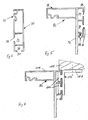
- the frame profile 10 has a main portion 12, with approximately rectangular cross-section, a plate-shaped mounting portion 14 and a rectangular tubular aperture portion 16.
- the attachment portion 14 is arranged at right angles to the main portion 12 and the diaphragm portion 16.
- the main portion 12 and the diaphragm portion 16 are arranged in alignment with each other and have a common side wall 18.
- the main portion 12 is formed approximately rectangular tube-shaped, but has two projecting into the rectangular tube-shaped interior grooves 20, 22.
- the frame profile 10 has a front side 26 which is formed by the front of the main portion 12 and the diaphragm portion 16, which are aligned with each other and thereby form the continuous front side 26.
- a rear wall 28 of the main portion 12 is in the region of its spaced from the side wall 18 end, which in the illustration of Fig. 1 left, provided with the two grooves 20, 22.
- the sealing profile 24 can thus project beyond the frame profile 10 with a sealing lip 30.
- the first groove 20 has a square cross section and forms at its, in the illustration of Fig. 1 left side wall by means of a projection 32 from an undercut.
- the projection 32 protrudes from a free side wall 34 of the main portion 12 in the direction of second groove 22 and the aperture portion 16 from.
- the second groove 22 has an inwardly curved side wall 36, which merges into a groove bottom. At the bottom of the groove is then followed by an opposite, approximately circular cylindrical section-shaped side wall.
- a projection 38 is provided which protrudes in the direction of the first groove 20 and the free side wall 34 of the main portion 12.
- the inwardly curved side wall 36 lies on the side of the groove 22 which is adjacent to the first groove 20.
- the sealing profile 24 is thereby held by means of the two projections 32, 38 on the frame profile 10, which are arranged facing each other.
- this can initially be inserted obliquely with a first, in cross-section wave-like projection 40 in the second groove 22.
- this then only has to be pressed into the first groove 20 with its second cross-sectionally square projection 42.
- the drawing of the sealing profile 24 in the grooves 20, 22 parallel to the longitudinal axis of the frame profile 10 is possible.
- the frame profile 10 is provided for attachment to a garage wall.
- the attachment portion 14 is either placed directly on the garage wall or one in the representation of Fig. 1 right side of the panel portion 16 is applied to the garage wall.
- the attachment portion 14 can then be secured by interposing spacers on the garage wall.
- spacers is usually required anyway, since garage walls are either not one hundred percent rectilinear or, for example, not executed vertically.
- the main section 12 then protrudes from the garage wall into the wall opening, which is to be closed by means of a garage door.
- Running rails for such a garage door are then at the attachment portion 14 attached.
- the rails are already preassembled on the mounting portion 14 and are fastened together with the frame profile 10 on the garage wall.
- the presentation of the Fig. 2 shows a further inventive frame profile, which is used for a horizontal frame that connects a right and a left column of a garage door frame together.
- the frame profile 44 of Fig. 2 is rectangular tube-shaped and has at the in Fig. 2 upper left corner two grooves 46, 48 which are identical to the grooves 20, 22 of the frame profile 10 and are also provided for suspending a sealing profile 24.
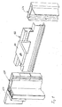
- the presentation of the Fig. 3 shows in exploded view a garage door frame 50, which consists of two vertical columns 52 and a horizontal frame 54.
- the columns 52a, 52b are each formed from a frame profile 10, as shown in FIG Fig. 1 is shown.
- the horizontal frame 54 is formed from a frame profile 44, as shown in FIG Fig. 2 is shown.
- the columns 52a, 52b are provided with a cutout 56 on their respective side walls 34 projecting into a wall opening on the main section 12.
- This cutout 56 has a width A, which corresponds to a distance between the inside of the front wall 26 and the inside of the rear wall 28 of the main portion 12.
- the distance A corresponds, as in Fig. 2 can be seen, even the width of the frame profile 44 minus the wall thickness of a front wall 62nd the frame profile 44.
- the frame 54 is therefore provided at its two ends, which are inserted into the cutouts 56, in the region of its front side with cutouts 64a, 64b.
- the cutouts 64a, 64b only remove the front wall 62 in these areas.
- a width of the frame 54 in the region of its ends but thus corresponds to the dimension A, ie the width of the cutout 56 and thus the clear width of the main portion 12 in the region of the cutout 56.
- the frame 54 can thus in the cutouts 56 in the columns 52 a, 52 b are inserted until the respective end of the cutouts 64 a, 64 b abuts the boundary of the cutouts 56.
- a rear side 66 of the frame 54 is in this state then on the inside of the rear wall 28 of the main portion 12 and on the inside of the webs 58, 60.
- the frame 54 is thus already arranged by simply plugging in at right angles to the columns 52a, 52b, and their front wall 62 is aligned with the respective front wall 26 of the columns 52a, 52b.
- the frame 54 When inserted, the frame 54 can then be connected in a very simple manner with the columns 52a, 52b by screws through the respective rear wall 28 of the columns 52a, 52b in the back 66 of the frame 54 are screwed. Corresponding holes for such screws are in the illustration of Fig. 3 designated by the reference numeral 68.
- the garage door frame 50 can then be attached to the respective garage walls.
- the sealing profile 24 can then be easily inserted into the grooves 46, 48 in the frame 54 as well as into the grooves 22, 20 in the columns 52a, 52b.
- a in Fig. 3 facing away from the viewer front of the garage door frame 50 has a substantially continuous surface. This surface then requires, if the surfaces of the columns 52a, 52b and the frame 54 are anodized, no post-processing. Only a gap between the top of the frame 54 and the lower edge of the garage door opening, which is approximately at the level of the upper end faces of the columns 52a, 52b, must still be filled with a diaphragm or an elastic mass.
- the invention makes it much easier to assemble garage door frames and garage doors.
- the assembly can be done faster, but above all, no great experience in aligning the columns 52, 52b and the frame 54 to each other is required for the assembly.
- the presentation of the Fig. 4 shows a front view of a frame profile 70 according to a second embodiment of the invention.
- a fastening section 72 for a sealing profile is identical to the frame profile 44 of FIG Fig. 2 executed.
- the frame profile 70 differs only by two rectangular chambers 74 and 76 from the frame profile 44 of Fig. 2 , Each of the two rectangular chambers 74, 76 is provided with an opening, so that in each case an undercut groove 78, 80 results.
- the grooves 78, 80 each extend over the entire length of the frame profile 70, so that, for example, a hooked into the groove 78 mounting angle along the entire frame profile 70 can be moved.
- the groove 78 is open to the side to which also the fastening portion 72 is open for the sealing profile.
- the groove 80 is open to the narrow side of the frame profile 70, which usually forms the top of the frame profile 70 in the mounted state.
- Fastening means can thus be suspended either in the undercut groove 78 on the rectangular chamber 74 or in the undercut groove 80 on the rectangular chamber 76. It is of course also possible to mount specially designed fasteners simultaneously in both undercut grooves 78, 80.
- the presentation of the Fig. 5 shows a frame profile 82 according to a second embodiment of the invention.
- the frame profile 82 differentiates itself from the frame profile 10 of the Fig. 1 essentially by providing three undercut grooves 84, 86, 88.
- the undercut groove 84 is formed by a lateral opening of a rectangular chamber 90, which in turn constitutes the diaphragm portion of the frame profile 82.
- the rectangular chamber 90 is adjoined in the direction of extension of the attachment section 92 by a further rectangular chamber 94, which is also opened laterally to form the further undercut groove 86.
- Both the rectangular chamber 90 and the rectangular chamber 94 are open towards a side facing away from the main section 96 of the frame profile 82.
- the rectangular chamber 94 is adjoined by a third rectangular chamber 98, which is open towards a side which lies in the extension direction of the attachment portion 92 from the main portion 96.
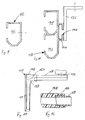
- FIG. 6 shows the frame profile 82 of Fig. 5 in an installed state.
- Schematically darg Congress is a portion 100 of a herefichen garage door opening.
- the mounting bracket 102 By means of a mounting bracket 102 having two hammer-head-like projections 104, which in turn are adapted to the undercut grooves 84, 86, the mounting bracket 102 is inserted into the undercut grooves 84, 86.
- a front side 106 of the mounting bracket 102 is then arranged flush with a front side 108 of the frame profile.
- the mounting bracket 106 can now be attached to the garage door opening 100 by means of bolts.
- the mounting bracket 102 can be attached to a very simple manner on the frame section 82 and beer in particular no holes in the frame section 82 must be drilled.
- the fastening angle 102 can be displaced along the entire length of the frame profile 82 in order to achieve a suitable position on the garage door opening 100. If necessary, the mounting bracket 102 can still be clamped by means of additional clamping screws on the frame section 82.
- the presentation of the Fig. 7 shows the frame profile 70 of Fig. 4 in an installed state.
- a garage door 110 is shown, which thus forms the upper boundary of a garage door opening.
- the mounting bracket 112 has two hammer-head-like projections 114, which are arranged at right angles to each other and adapted to the dimensions of the undercut grooves.
- a mounting surface 116 of the mounting bracket 112 is then flush with a front side 118 of the frame profile 70.
- the mounting bracket 112 can be attached to the frame profile 70 in a very simple manner and only if it is necessary, the mounting bracket can be secured on the frame profile 70, for example, with additional clamping screws.
- the mounting bracket 112 can easily move along the entire length of the frame profile 70 to find a suitable location for the attachment. This is of particular advantage in half-timbered buildings.
- FIG. 8 shows a perspective view of a garage door frame according to the invention, wherein only by way of example on the left side of Fig. 8 an inventive frame profile 120 is shown according to a third embodiment of the invention and the frame of the garage door frame is formed by an inventive frame profile 122 according to a third embodiment.
- right column 52b corresponds to in Fig. 3 shown.
- the frame profile 120 is provided with only two undercut grooves into which a mounting bracket 124 in an analogous manner Fig. 6 is introduced.
- the frame profile 122 is provided with only an undercut groove into which a mounting bracket 126 is inserted.
- column 52b is shown.
- the presentation of the Fig. 9 shows in front view a straight roller guide portion 130 for a roller guide path of a garage door frame.
- the roller guide portion 130 is formed as an aluminum extruded profile and has a first, laterally sectionally open chamber 132, which serves as a roller guide track.
- the roller guide portion 130 is bolted directly to the attachment portion 14, 92 of a frame profile 10, 82, 120.
- the presentation of the Fig. 10 shows a roller guide section 138 according to another embodiment of the invention.
- the roller guide portion 138 is designed as an aluminum extruded profile and laterally provided with a rectangular chamber 144 which is open at the side and forms an undercut groove 146.
- the roller guide section 138 can be fastened to a garage ceiling with the aid of suitable fastening means, for example a mounting bracket 136, without having to attach additional holes to the roller guide section 138.
- both roller guide sections 130, 138 are rectilinear, the two roller guide sections 130, 138 become, as in FIG Fig. 11 shown combined by means of a corner portion 148 to a roller guide track having a right-angled bend.
- This turning portion 150 of the roller guide path is formed in the corner portion 148 and in the illustration of Fig. 11 indicated by dashed lines.
- the corner portion 148 has an S-like extending portion 152 of a roller guide path, which is provided at a sectional door for the uppermost segment of the sectional door, namely to bring the upper edge of the uppermost portion in a vertical position.
- roller guide portions 130, 138 are respectively inserted into the corner portion 148 having suitable recesses therefor to ensure a continuous and substantially uninterrupted roller guideway between corner portion 148 and the roller guide portions 130, 138 and additionally secure retention of the roller guide portions 130, 138 in the corner portion 148 to ensure.
- FIG. 12 The schematic, enlarged sectional view of Fig. 12 shows such a recess 154 in the corner portion 148.
- the recess 154 has a shoulder on which the fully inserted roller guide portion 138 abuts and is thus fixed in its end position.
- a continuous and substantially uninterrupted roller guide surface is provided and at the same time the roller guide portion 138 is securely held on the corner portion 148.
- Both the corner portion 148 and the roller guide portion 130 are bolted to the attachment portion of the frame profile 120 that forms the pillar of a garage door frame.
- the roller guide portion 138 is fixed to a garage ceiling by the fixing bracket 136. Since the mounting bracket 136 can be slid in the groove 146 of the roller guide section 138, an optimal location for fixing can be selected.
- the presentation of the Fig. 13 shows a plan view of the rear, from the garage door recessed portion of a garage door frame according to the invention, on which a pulley 160 is arranged, on which a cable 162 is wound, which in turn is connected to the garage door itself.
- the pulley 160 is disposed on a rotatably mounted shaft 164 which is acted upon by a torsion spring, not shown, and on which a spring break brake 166 indicated only schematically. It is of course also possible to electrically drive the shaft 164.
- the roller guide portion 138 is connected at its rear, the garage door facing away from the end with a mounting profile 168 having a mounting portion 170, a first leg 172, a second leg 174 and a base 176.
- the fixing portion 170, the first leg 172 and the second leg 174 are aligned parallel to each other and parallel to the extending direction of the roller guide portion 138.
- the base 176 extends perpendicular thereto and connects the attachment portion 170 and the first and second legs 172, 174.
- a stiffening strut 178 is disposed at an angle of 45 °.
- the mounting profile 168 is formed as an aluminum extruded profile.
- the mounting profile 168 By means of the mounting profile 168 a considerably simplified arrangement of the cable drive is possible. Because of the provision of the first leg 172 and the second leg 174 and the mounting portion 170, the lateral distances for the assembly of the spring break brake 166 and a bearing 180 for the shaft 164 are specified exactly and above all in relation to the roller guide portion 138. A mechanic does not have to make the tedious lateral alignment of the spring break brake 166 and the arrangement of the pulley 160 itself, as this is predetermined by the mounting profile 180.
- the base 176 is significantly wider than the pulley 160 so that enough space is available for screwing the spring break brake 166 and other adjustments. Especially when the garage door recessed cable drives that require a particularly precise alignment of the pulley 160 relative to the roller guide portion 138, the mounting profile 168 facilitates the assembly considerably.
Landscapes
- Engineering & Computer Science (AREA)
- Mechanical Engineering (AREA)
- Civil Engineering (AREA)
- Structural Engineering (AREA)
- Gates (AREA)
- Door And Window Frames Mounted To Openings (AREA)
Claims (15)
- Profilé de cadre pour un cadre de porte de garage comprenant une partie principale (12) et au moins une rainure (20, 22) s'étendant dans la direction longitudinale du profilé de cadre pour accrocher un profilé d'étanchéité élastique (24), la partie principale (12) étant réalisée sous forme de tube rectangulaire, et une partie de fixation (14) s'étendant suivant un angle droit depuis la partie principale (12) ainsi qu'une partie de bandeau (16) s'étendant dans le prolongement de la partie principale (12) étant prévues, le profilé de cadre (10) étant réalisé d'une seule pièce, la partie de fixation s'étendant à partir d'une position au niveau de la transition entre la partie principale (12) et la partie de bandeau (16) et, vu dans sa direction d'étendue, faisant saillie au-delà de la partie principale (12) et de la partie de bandeau (16), caractérisé en ce que la partie de fixation (14) est réalisée en forme de plaque et en ce que la partie de bandeau (16), vu dans sa direction d'étendue, dépasse librement par rapport à la partie de fixation (14).
- Profilé de cadre selon la revendication 1, caractérisé en ce que la partie de bandeau (16) est réalisée sous forme de tube rectangulaire et un côté avant de la partie de bandeau (16) et un côté avant de la partie principale (12) sont disposés en affleurement l'un à l'autre.
- Profilé de cadre selon la revendication 1, caractérisé en ce qu'un prolongement de la partie de fixation (14) forme une paroi latérale (18) de la partie principale (12).
- Profilé de cadre selon l'une quelconque des revendications précédentes, caractérisé en ce que deux rainures (20, 22 ; 46, 48) s'étendant dans la direction longitudinale du profilé de cadre (10 ; 44) et espacées l'une de l'autre sont prévues au niveau de la partie principale (12) pour accrocher un profilé d'étanchéité ajusté (24) pourvu de deux saillies (40, 42) s'étendant dans la direction longitudinale.
- Profilé de cadre selon la revendication 4, caractérisé en ce qu'une première (20 ; 46) des deux rainures présente une section transversale rectangulaire et une deuxième (22 ; 48) des deux rainures présente une paroi latérale (36) courbée vers l'intérieur et se prolongeant dans une base de rainure, la paroi latérale courbée vers l'intérieur (36) étant disposée à côté de la première rainure (20 ; 46).
- Profilé de cadre selon la revendication 5, caractérisé en ce que la deuxième rainure (22 ; 48) présente une contre-dépouille à l'opposé de la paroi latérale (36) courbée vers l'intérieur.
- Profilé de cadre selon la revendication 6, caractérisé en ce que la première rainure (20 ; 46) présente une contre-dépouille dans une paroi latérale, la contre-dépouille dans la première rainure (20 ; 46) étant formée au moyen d'une saillie (32) faisant saillie dans la direction de la deuxième rainure (22 ; 48) et la contre-dépouille dans la deuxième rainure (22 ; 48) étant formée au moyen d'une saillie (38) faisant saillie dans la direction de la première rainure (20 ; 46).
- Profilé de cadre selon l'une quelconque des revendications précédentes, caractérisé en ce que la partie de bandeau et/ou la partie de fixation sont pourvues d'au moins une rainure en contre-dépouille pour l'agencement de moyens de fixation.
- Profilé de cadre selon la revendication 8, caractérisé en ce que la rainure en contre-dépouille est ouverte au niveau de la partie de bandeau et/ou au niveau de la partie de fixation vers un côté opposé à la partie principale.
- Profilé de cadre selon la revendication 8 ou 9, caractérisé en ce que la rainure en contre-dépouille est ouverte au niveau de la partie de bandeau et/ou au niveau de la partie de fixation vers un côté dans lequel la partie de fixation s'étend à partir de la partie principale.
- Cadre de porte de garage comprenant au moins deux profilés de cadre selon l'une quelconque des revendications précédentes, les profilés de cadre formant deux colonnes espacées l'une de l'autre (52a, 52b) et un dormant (54) reliant les colonnes (52a, 52b) étant prévu, les colonnes (52a, 52b) étant pourvues, au niveau des parois latérales tournées l'une vers l'autre (34), de découpes par fraisage (56) pour enficher le dormant (54).
- Cadre de porte de garage selon la revendication 11, caractérisé en ce qu'une paroi avant (62) du dormant (54) est pourvue, dans une région enfichée dans les colonnes (52a, 52b), d'une découpe par fraisage (64a, 64b), une hauteur de la découpe par fraisage (64a, 64b) correspondant à une épaisseur de paroi d'une paroi avant (26) des colonnes (52a, 52b).
- Cadre de porte de garage selon la revendication 11, caractérisé en ce qu'une hauteur du dormant (54) moins la hauteur de la découpe par fraisage (64a, 64b) correspond à une largeur intérieure (A) de la partie principale en forme de tube rectangulaire (12) des colonnes (52a, 52b) dans la région de la découpe par fraisage (56).
- Cadre de porte de garage selon la revendication 11, 12 ou 13, caractérisé en ce qu'un guide de rouleaux pour des rouleaux de guidage est prévu sur chaque colonne, le guide de rouleaux présentant un coudage d'environ 90°, caractérisé en ce que le guide de rouleaux présente au moins deux parties de guidage de rouleaux rectilignes qui sont connectées l'une à l'autre au moyen d'une partie de coin suivant un angle d'environ 90°, la partie de coin présentant le coudage du guide à rouleaux.
- Cadre de porte de garage selon la revendication 14, caractérisé en ce que la partie de coin est réalisée sous forme de partie en plastique.
Priority Applications (1)
| Application Number | Priority Date | Filing Date | Title |
|---|---|---|---|
| PL09761459T PL2304151T3 (pl) | 2008-06-10 | 2009-06-09 | Profil ramowy, ościeżnica i rama bramy garażowej |
Applications Claiming Priority (3)
| Application Number | Priority Date | Filing Date | Title |
|---|---|---|---|
| DE102008029073A DE102008029073B3 (de) | 2008-06-10 | 2008-06-10 | Rahmenprofil für Garagentore und Garagentorrahmen |
| DE202009005317U DE202009005317U1 (de) | 2008-06-10 | 2009-03-31 | Rahmenprofil und Zarge und Garagentorrahmen |
| PCT/EP2009/004140 WO2009149896A1 (fr) | 2008-06-10 | 2009-06-09 | Profilé de cadre, dormant et cadre de porte de garage |
Publications (2)
| Publication Number | Publication Date |
|---|---|
| EP2304151A1 EP2304151A1 (fr) | 2011-04-06 |
| EP2304151B1 true EP2304151B1 (fr) | 2015-08-12 |
Family
ID=41254358
Family Applications (1)
| Application Number | Title | Priority Date | Filing Date |
|---|---|---|---|
| EP09761459.8A Active EP2304151B1 (fr) | 2008-06-10 | 2009-06-09 | Profilé de cadre, dormant et cadre de porte de garage |
Country Status (6)
| Country | Link |
|---|---|
| EP (1) | EP2304151B1 (fr) |
| DE (2) | DE102008029073B3 (fr) |
| HU (1) | HUE026607T2 (fr) |
| PL (1) | PL2304151T3 (fr) |
| PT (1) | PT2304151E (fr) |
| WO (1) | WO2009149896A1 (fr) |
Family Cites Families (5)
| Publication number | Priority date | Publication date | Assignee | Title |
|---|---|---|---|---|
| DE4325698C2 (de) | 1993-07-30 | 1999-12-02 | Hoermann Kg | Nebentür |
| FR2779760B1 (fr) | 1998-06-12 | 2002-10-25 | Fermetures Le Nouy Sa | Dispositif permettant la fermeture d'une porte de garage hermetiquement |
| IT1319254B1 (it) | 2000-10-30 | 2003-09-26 | Hydro Aluminium Systems Spa | Profilato portante per un telaio di una finestra, elemento difissaggio di un vetro e guarnizione di tenuta, associati a detto |
| DE20208997U1 (de) * | 2002-06-11 | 2002-11-14 | H & K Teckentrup KG, 33415 Verl | Garagenschwingtor |
| DE20309285U1 (de) | 2002-06-13 | 2003-10-16 | Weil, Lothar, 65558 Flacht | Tor, insbesondere Sektionaltor, mit einem Torblatt und Antriebs- und Führungsmitteln für das Torblatt |
-
2008
- 2008-06-10 DE DE102008029073A patent/DE102008029073B3/de not_active Expired - Fee Related
-
2009
- 2009-03-31 DE DE202009005317U patent/DE202009005317U1/de not_active Expired - Lifetime
- 2009-06-09 PT PT97614598T patent/PT2304151E/pt unknown
- 2009-06-09 HU HUE09761459A patent/HUE026607T2/hu unknown
- 2009-06-09 WO PCT/EP2009/004140 patent/WO2009149896A1/fr not_active Ceased
- 2009-06-09 PL PL09761459T patent/PL2304151T3/pl unknown
- 2009-06-09 EP EP09761459.8A patent/EP2304151B1/fr active Active
Also Published As
| Publication number | Publication date |
|---|---|
| WO2009149896A1 (fr) | 2009-12-17 |
| DE202009005317U1 (de) | 2009-10-29 |
| EP2304151A1 (fr) | 2011-04-06 |
| PT2304151E (pt) | 2015-11-25 |
| DE102008029073B3 (de) | 2010-01-21 |
| HUE026607T2 (hu) | 2016-06-28 |
| PL2304151T3 (pl) | 2016-03-31 |
Similar Documents
| Publication | Publication Date | Title |
|---|---|---|
| EP3401495B2 (fr) | Construction de façade/fenêtre et installation de protection solaire correspondante | |
| DE202011102244U1 (de) | Rahmensystem für ein Insekten-und/oder Pollenschutzgitter | |
| DE3435300A1 (de) | Plattenfoermiges bauelement | |
| EP1710388B1 (fr) | Caisson de volet roulant posé sur un cadre | |
| DE2517009A1 (de) | Profilschienensatz fuer fenster- und fenstertuerrahmen | |
| AT516721B1 (de) | Geländer und Verfahren zur Herstellung eines Geländers | |
| EP2304151B1 (fr) | Profilé de cadre, dormant et cadre de porte de garage | |
| EP3957815B1 (fr) | Dispositif d'ombrage au-dessus des ouvertures d'angle de fenêtre ou de porte | |
| DE19744832A1 (de) | Anordnung für den Einbau eines Fensterrahmens | |
| CH702394B1 (de) | Schiebewand mit wenigstens zwei Flügeln. | |
| DE202012002574U1 (de) | Pfostenverbinder | |
| DE102006004493B4 (de) | Führungsschienenbefestigung | |
| CH705792B1 (de) | Modulares Fensterkomplettsystem. | |
| EP3441557B1 (fr) | Dispositif formant portail comportant un dispostif formant porte | |
| EP2072744B1 (fr) | Profilés dormants pour une porte coulissante relevable | |
| DE102012005091A1 (de) | Pfostenverbinder | |
| EP1864000B1 (fr) | Vantail de porte ou de fenetre et procede de fabrication associe | |
| EP3244001B1 (fr) | Porte comprenant une piece de serrage commandee par ressort et son procede de montage | |
| DE102012005295B3 (de) | Pfostenverbinder | |
| DE4027335A1 (de) | Halterungsanordung fuer glasscheiben in toren | |
| EP1980702B1 (fr) | Construction de cadre pour fenêtres et/ou portes | |
| EP2182157B1 (fr) | Ecran pour un espace entre un dormant de porte ou de portail et intrados | |
| DE20203512U1 (de) | Rahmensystemanordnung | |
| DE202004010160U1 (de) | Universalprofil | |
| EP3216968B1 (fr) | Support central pour une ouverture de bâtiment ayant une grande largeur intérieure |
Legal Events
| Date | Code | Title | Description |
|---|---|---|---|
| PUAI | Public reference made under article 153(3) epc to a published international application that has entered the european phase |
Free format text: ORIGINAL CODE: 0009012 |
|
| 17P | Request for examination filed |
Effective date: 20110104 |
|
| AK | Designated contracting states |
Kind code of ref document: A1 Designated state(s): AT BE BG CH CY CZ DE DK EE ES FI FR GB GR HR HU IE IS IT LI LT LU LV MC MK MT NL NO PL PT RO SE SI SK TR |
|
| AX | Request for extension of the european patent |
Extension state: AL BA RS |
|
| RIN1 | Information on inventor provided before grant (corrected) |
Inventor name: CETIN, YUECEL |
|
| DAX | Request for extension of the european patent (deleted) | ||
| 17Q | First examination report despatched |
Effective date: 20120827 |
|
| GRAP | Despatch of communication of intention to grant a patent |
Free format text: ORIGINAL CODE: EPIDOSNIGR1 |
|
| INTG | Intention to grant announced |
Effective date: 20150330 |
|
| GRAS | Grant fee paid |
Free format text: ORIGINAL CODE: EPIDOSNIGR3 |
|
| RAP1 | Party data changed (applicant data changed or rights of an application transferred) |
Owner name: FRANKENTORE E.K. |
|
| GRAA | (expected) grant |
Free format text: ORIGINAL CODE: 0009210 |
|
| AK | Designated contracting states |
Kind code of ref document: B1 Designated state(s): AT BE BG CH CY CZ DE DK EE ES FI FR GB GR HR HU IE IS IT LI LT LU LV MC MK MT NL NO PL PT RO SE SI SK TR |
|
| REG | Reference to a national code |
Ref country code: GB Ref legal event code: FG4D Free format text: NOT ENGLISH |
|
| REG | Reference to a national code |
Ref country code: CH Ref legal event code: EP |
|
| REG | Reference to a national code |
Ref country code: AT Ref legal event code: REF Ref document number: 742335 Country of ref document: AT Kind code of ref document: T Effective date: 20150815 |
|
| REG | Reference to a national code |
Ref country code: IE Ref legal event code: FG4D Free format text: LANGUAGE OF EP DOCUMENT: GERMAN |
|
| REG | Reference to a national code |
Ref country code: DE Ref legal event code: R096 Ref document number: 502009011416 Country of ref document: DE |
|
| REG | Reference to a national code |
Ref country code: RO Ref legal event code: EPE |
|
| REG | Reference to a national code |
Ref country code: PT Ref legal event code: SC4A Free format text: AVAILABILITY OF NATIONAL TRANSLATION Effective date: 20151111 |
|
| REG | Reference to a national code |
Ref country code: CH Ref legal event code: NV Representative=s name: DR. LUSUARDI AG, CH |
|
| REG | Reference to a national code |
Ref country code: NL Ref legal event code: FP |
|
| PG25 | Lapsed in a contracting state [announced via postgrant information from national office to epo] |
Ref country code: FI Free format text: LAPSE BECAUSE OF FAILURE TO SUBMIT A TRANSLATION OF THE DESCRIPTION OR TO PAY THE FEE WITHIN THE PRESCRIBED TIME-LIMIT Effective date: 20150812 Ref country code: NO Free format text: LAPSE BECAUSE OF FAILURE TO SUBMIT A TRANSLATION OF THE DESCRIPTION OR TO PAY THE FEE WITHIN THE PRESCRIBED TIME-LIMIT Effective date: 20151112 Ref country code: LV Free format text: LAPSE BECAUSE OF FAILURE TO SUBMIT A TRANSLATION OF THE DESCRIPTION OR TO PAY THE FEE WITHIN THE PRESCRIBED TIME-LIMIT Effective date: 20150812 Ref country code: GR Free format text: LAPSE BECAUSE OF FAILURE TO SUBMIT A TRANSLATION OF THE DESCRIPTION OR TO PAY THE FEE WITHIN THE PRESCRIBED TIME-LIMIT Effective date: 20151113 |
|
| PG25 | Lapsed in a contracting state [announced via postgrant information from national office to epo] |
Ref country code: IS Free format text: LAPSE BECAUSE OF FAILURE TO SUBMIT A TRANSLATION OF THE DESCRIPTION OR TO PAY THE FEE WITHIN THE PRESCRIBED TIME-LIMIT Effective date: 20151212 Ref country code: ES Free format text: LAPSE BECAUSE OF FAILURE TO SUBMIT A TRANSLATION OF THE DESCRIPTION OR TO PAY THE FEE WITHIN THE PRESCRIBED TIME-LIMIT Effective date: 20150812 Ref country code: HR Free format text: LAPSE BECAUSE OF FAILURE TO SUBMIT A TRANSLATION OF THE DESCRIPTION OR TO PAY THE FEE WITHIN THE PRESCRIBED TIME-LIMIT Effective date: 20150812 Ref country code: SE Free format text: LAPSE BECAUSE OF FAILURE TO SUBMIT A TRANSLATION OF THE DESCRIPTION OR TO PAY THE FEE WITHIN THE PRESCRIBED TIME-LIMIT Effective date: 20150812 |
|
| PG25 | Lapsed in a contracting state [announced via postgrant information from national office to epo] |
Ref country code: EE Free format text: LAPSE BECAUSE OF FAILURE TO SUBMIT A TRANSLATION OF THE DESCRIPTION OR TO PAY THE FEE WITHIN THE PRESCRIBED TIME-LIMIT Effective date: 20150812 Ref country code: DK Free format text: LAPSE BECAUSE OF FAILURE TO SUBMIT A TRANSLATION OF THE DESCRIPTION OR TO PAY THE FEE WITHIN THE PRESCRIBED TIME-LIMIT Effective date: 20150812 |
|
| REG | Reference to a national code |
Ref country code: SK Ref legal event code: T3 Ref document number: E 19871 Country of ref document: SK |
|
| REG | Reference to a national code |
Ref country code: DE Ref legal event code: R097 Ref document number: 502009011416 Country of ref document: DE |
|
| PLBE | No opposition filed within time limit |
Free format text: ORIGINAL CODE: 0009261 |
|
| STAA | Information on the status of an ep patent application or granted ep patent |
Free format text: STATUS: NO OPPOSITION FILED WITHIN TIME LIMIT |
|
| REG | Reference to a national code |
Ref country code: FR Ref legal event code: PLFP Year of fee payment: 8 |
|
| REG | Reference to a national code |
Ref country code: HU Ref legal event code: AG4A Ref document number: E026607 Country of ref document: HU |
|
| 26N | No opposition filed |
Effective date: 20160513 |
|
| PG25 | Lapsed in a contracting state [announced via postgrant information from national office to epo] |
Ref country code: SI Free format text: LAPSE BECAUSE OF FAILURE TO SUBMIT A TRANSLATION OF THE DESCRIPTION OR TO PAY THE FEE WITHIN THE PRESCRIBED TIME-LIMIT Effective date: 20150812 |
|
| PG25 | Lapsed in a contracting state [announced via postgrant information from national office to epo] |
Ref country code: MC Free format text: LAPSE BECAUSE OF FAILURE TO SUBMIT A TRANSLATION OF THE DESCRIPTION OR TO PAY THE FEE WITHIN THE PRESCRIBED TIME-LIMIT Effective date: 20150812 |
|
| REG | Reference to a national code |
Ref country code: IE Ref legal event code: MM4A |
|
| PG25 | Lapsed in a contracting state [announced via postgrant information from national office to epo] |
Ref country code: IE Free format text: LAPSE BECAUSE OF NON-PAYMENT OF DUE FEES Effective date: 20160609 |
|
| REG | Reference to a national code |
Ref country code: FR Ref legal event code: PLFP Year of fee payment: 9 |
|
| PG25 | Lapsed in a contracting state [announced via postgrant information from national office to epo] |
Ref country code: CY Free format text: LAPSE BECAUSE OF FAILURE TO SUBMIT A TRANSLATION OF THE DESCRIPTION OR TO PAY THE FEE WITHIN THE PRESCRIBED TIME-LIMIT Effective date: 20150812 |
|
| REG | Reference to a national code |
Ref country code: FR Ref legal event code: PLFP Year of fee payment: 10 |
|
| PG25 | Lapsed in a contracting state [announced via postgrant information from national office to epo] |
Ref country code: MT Free format text: LAPSE BECAUSE OF FAILURE TO SUBMIT A TRANSLATION OF THE DESCRIPTION OR TO PAY THE FEE WITHIN THE PRESCRIBED TIME-LIMIT Effective date: 20150812 Ref country code: LU Free format text: LAPSE BECAUSE OF NON-PAYMENT OF DUE FEES Effective date: 20160609 Ref country code: MK Free format text: LAPSE BECAUSE OF FAILURE TO SUBMIT A TRANSLATION OF THE DESCRIPTION OR TO PAY THE FEE WITHIN THE PRESCRIBED TIME-LIMIT Effective date: 20150812 |
|
| PG25 | Lapsed in a contracting state [announced via postgrant information from national office to epo] |
Ref country code: BG Free format text: LAPSE BECAUSE OF FAILURE TO SUBMIT A TRANSLATION OF THE DESCRIPTION OR TO PAY THE FEE WITHIN THE PRESCRIBED TIME-LIMIT Effective date: 20150812 |
|
| PGFP | Annual fee paid to national office [announced via postgrant information from national office to epo] |
Ref country code: IT Payment date: 20210630 Year of fee payment: 13 |
|
| PGFP | Annual fee paid to national office [announced via postgrant information from national office to epo] |
Ref country code: GB Payment date: 20210623 Year of fee payment: 13 |
|
| PGFP | Annual fee paid to national office [announced via postgrant information from national office to epo] |
Ref country code: PT Payment date: 20220527 Year of fee payment: 14 Ref country code: LT Payment date: 20220530 Year of fee payment: 14 Ref country code: CZ Payment date: 20220603 Year of fee payment: 14 |
|
| GBPC | Gb: european patent ceased through non-payment of renewal fee |
Effective date: 20220609 |
|
| PG25 | Lapsed in a contracting state [announced via postgrant information from national office to epo] |
Ref country code: GB Free format text: LAPSE BECAUSE OF NON-PAYMENT OF DUE FEES Effective date: 20220609 |
|
| REG | Reference to a national code |
Ref country code: DE Ref legal event code: R081 Ref document number: 502009011416 Country of ref document: DE Owner name: CETIN, OEMER, DE Free format text: FORMER OWNER: FRANKENTORE E.K., 74078 HEILBRONN, DE |
|
| PG25 | Lapsed in a contracting state [announced via postgrant information from national office to epo] |
Ref country code: IT Free format text: LAPSE BECAUSE OF NON-PAYMENT OF DUE FEES Effective date: 20220609 |
|
| PGFP | Annual fee paid to national office [announced via postgrant information from national office to epo] |
Ref country code: RO Payment date: 20230802 Year of fee payment: 15 |
|
| PGFP | Annual fee paid to national office [announced via postgrant information from national office to epo] |
Ref country code: SK Payment date: 20230803 Year of fee payment: 15 Ref country code: HU Payment date: 20230803 Year of fee payment: 15 |
|
| REG | Reference to a national code |
Ref country code: LT Ref legal event code: MM4D Effective date: 20230609 |
|
| PG25 | Lapsed in a contracting state [announced via postgrant information from national office to epo] |
Ref country code: PT Free format text: LAPSE BECAUSE OF NON-PAYMENT OF DUE FEES Effective date: 20231211 Ref country code: CZ Free format text: LAPSE BECAUSE OF NON-PAYMENT OF DUE FEES Effective date: 20230609 |
|
| PG25 | Lapsed in a contracting state [announced via postgrant information from national office to epo] |
Ref country code: LT Free format text: LAPSE BECAUSE OF NON-PAYMENT OF DUE FEES Effective date: 20230609 |
|
| PG25 | Lapsed in a contracting state [announced via postgrant information from national office to epo] |
Ref country code: LT Free format text: LAPSE BECAUSE OF NON-PAYMENT OF DUE FEES Effective date: 20230609 |
|
| PGFP | Annual fee paid to national office [announced via postgrant information from national office to epo] |
Ref country code: AT Payment date: 20240617 Year of fee payment: 16 |
|
| PGFP | Annual fee paid to national office [announced via postgrant information from national office to epo] |
Ref country code: BE Payment date: 20240618 Year of fee payment: 16 |
|
| PGFP | Annual fee paid to national office [announced via postgrant information from national office to epo] |
Ref country code: DE Payment date: 20240723 Year of fee payment: 16 |
|
| PGFP | Annual fee paid to national office [announced via postgrant information from national office to epo] |
Ref country code: CH Payment date: 20240722 Year of fee payment: 16 |
|
| PGFP | Annual fee paid to national office [announced via postgrant information from national office to epo] |
Ref country code: NL Payment date: 20241120 Year of fee payment: 16 |
|
| PGFP | Annual fee paid to national office [announced via postgrant information from national office to epo] |
Ref country code: PL Payment date: 20241104 Year of fee payment: 16 |
|
| PGFP | Annual fee paid to national office [announced via postgrant information from national office to epo] |
Ref country code: FR Payment date: 20241118 Year of fee payment: 16 |
|
| PG25 | Lapsed in a contracting state [announced via postgrant information from national office to epo] |
Ref country code: RO Free format text: LAPSE BECAUSE OF NON-PAYMENT OF DUE FEES Effective date: 20240609 |
|
| REG | Reference to a national code |
Ref country code: SK Ref legal event code: MM4A Ref document number: E 19871 Country of ref document: SK Effective date: 20240609 |
|
| PG25 | Lapsed in a contracting state [announced via postgrant information from national office to epo] |
Ref country code: RO Free format text: LAPSE BECAUSE OF NON-PAYMENT OF DUE FEES Effective date: 20240609 |
|
| PGFP | Annual fee paid to national office [announced via postgrant information from national office to epo] |
Ref country code: TR Payment date: 20241128 Year of fee payment: 16 |
|
| PG25 | Lapsed in a contracting state [announced via postgrant information from national office to epo] |
Ref country code: HU Free format text: LAPSE BECAUSE OF NON-PAYMENT OF DUE FEES Effective date: 20240610 |
|
| PG25 | Lapsed in a contracting state [announced via postgrant information from national office to epo] |
Ref country code: SK Free format text: LAPSE BECAUSE OF NON-PAYMENT OF DUE FEES Effective date: 20240609 |
|
| REG | Reference to a national code |
Ref country code: DE Ref legal event code: R119 Ref document number: 502009011416 Country of ref document: DE |
|
| REG | Reference to a national code |
Ref country code: CH Ref legal event code: H13 Free format text: ST27 STATUS EVENT CODE: U-0-0-H10-H13 (AS PROVIDED BY THE NATIONAL OFFICE) Effective date: 20260127 |
|
| REG | Reference to a national code |
Ref country code: NL Ref legal event code: MM Effective date: 20250701 |
|
| REG | Reference to a national code |
Ref country code: AT Ref legal event code: MM01 Ref document number: 742335 Country of ref document: AT Kind code of ref document: T Effective date: 20250609 |
|
| REG | Reference to a national code |
Ref country code: BE Ref legal event code: MM Effective date: 20250630 |
|
| PG25 | Lapsed in a contracting state [announced via postgrant information from national office to epo] |
Ref country code: NL Free format text: LAPSE BECAUSE OF NON-PAYMENT OF DUE FEES Effective date: 20250701 |
|
| PG25 | Lapsed in a contracting state [announced via postgrant information from national office to epo] |
Ref country code: DE Free format text: LAPSE BECAUSE OF NON-PAYMENT OF DUE FEES Effective date: 20260101 |
|
| PG25 | Lapsed in a contracting state [announced via postgrant information from national office to epo] |
Ref country code: AT Free format text: LAPSE BECAUSE OF NON-PAYMENT OF DUE FEES Effective date: 20250609 |
|
| PG25 | Lapsed in a contracting state [announced via postgrant information from national office to epo] |
Ref country code: BE Free format text: LAPSE BECAUSE OF NON-PAYMENT OF DUE FEES Effective date: 20250630 |
|
| PG25 | Lapsed in a contracting state [announced via postgrant information from national office to epo] |
Ref country code: FR Free format text: LAPSE BECAUSE OF NON-PAYMENT OF DUE FEES Effective date: 20250630 |
|
| PG25 | Lapsed in a contracting state [announced via postgrant information from national office to epo] |
Ref country code: CH Free format text: LAPSE BECAUSE OF NON-PAYMENT OF DUE FEES Effective date: 20250630 |