EP2304301B1 - Ensemble avec une ferrure, un elément de transmission de force et une bague coulissante, ensemble et procédé de fabrication d'une liaison de pièces non détachable - Google Patents
Ensemble avec une ferrure, un elément de transmission de force et une bague coulissante, ensemble et procédé de fabrication d'une liaison de pièces non détachable Download PDFInfo
- Publication number
- EP2304301B1 EP2304301B1 EP20090780255 EP09780255A EP2304301B1 EP 2304301 B1 EP2304301 B1 EP 2304301B1 EP 20090780255 EP20090780255 EP 20090780255 EP 09780255 A EP09780255 A EP 09780255A EP 2304301 B1 EP2304301 B1 EP 2304301B1
- Authority
- EP
- European Patent Office
- Prior art keywords
- sliding sleeve
- peripheral surface
- force
- fitting
- transmission element
- Prior art date
- Legal status (The legal status is an assumption and is not a legal conclusion. Google has not performed a legal analysis and makes no representation as to the accuracy of the status listed.)
- Active
Links
Images

Classifications
-
- F—MECHANICAL ENGINEERING; LIGHTING; HEATING; WEAPONS; BLASTING
- F16—ENGINEERING ELEMENTS AND UNITS; GENERAL MEASURES FOR PRODUCING AND MAINTAINING EFFECTIVE FUNCTIONING OF MACHINES OR INSTALLATIONS; THERMAL INSULATION IN GENERAL
- F16L—PIPES; JOINTS OR FITTINGS FOR PIPES; SUPPORTS FOR PIPES, CABLES OR PROTECTIVE TUBING; MEANS FOR THERMAL INSULATION IN GENERAL
- F16L13/00—Non-disconnectable pipe joints, e.g. soldered, adhesive, or caulked joints
- F16L13/14—Non-disconnectable pipe joints, e.g. soldered, adhesive, or caulked joints made by plastically deforming the material of the pipe, e.g. by flanging, rolling
- F16L13/146—Non-disconnectable pipe joints, e.g. soldered, adhesive, or caulked joints made by plastically deforming the material of the pipe, e.g. by flanging, rolling by an axially moveable sleeve
-
- F—MECHANICAL ENGINEERING; LIGHTING; HEATING; WEAPONS; BLASTING
- F16—ENGINEERING ELEMENTS AND UNITS; GENERAL MEASURES FOR PRODUCING AND MAINTAINING EFFECTIVE FUNCTIONING OF MACHINES OR INSTALLATIONS; THERMAL INSULATION IN GENERAL
- F16L—PIPES; JOINTS OR FITTINGS FOR PIPES; SUPPORTS FOR PIPES, CABLES OR PROTECTIVE TUBING; MEANS FOR THERMAL INSULATION IN GENERAL
- F16L13/00—Non-disconnectable pipe joints, e.g. soldered, adhesive, or caulked joints
- F16L13/14—Non-disconnectable pipe joints, e.g. soldered, adhesive, or caulked joints made by plastically deforming the material of the pipe, e.g. by flanging, rolling
- F16L13/141—Non-disconnectable pipe joints, e.g. soldered, adhesive, or caulked joints made by plastically deforming the material of the pipe, e.g. by flanging, rolling by crimping or rolling from the outside
-
- F—MECHANICAL ENGINEERING; LIGHTING; HEATING; WEAPONS; BLASTING
- F16—ENGINEERING ELEMENTS AND UNITS; GENERAL MEASURES FOR PRODUCING AND MAINTAINING EFFECTIVE FUNCTIONING OF MACHINES OR INSTALLATIONS; THERMAL INSULATION IN GENERAL
- F16L—PIPES; JOINTS OR FITTINGS FOR PIPES; SUPPORTS FOR PIPES, CABLES OR PROTECTIVE TUBING; MEANS FOR THERMAL INSULATION IN GENERAL
- F16L33/00—Arrangements for connecting hoses to rigid members; Rigid hose-connectors, i.e. single members engaging both hoses
- F16L33/22—Arrangements for connecting hoses to rigid members; Rigid hose-connectors, i.e. single members engaging both hoses with means not mentioned in the preceding groups for gripping the hose between inner and outer parts
- F16L33/225—Arrangements for connecting hoses to rigid members; Rigid hose-connectors, i.e. single members engaging both hoses with means not mentioned in the preceding groups for gripping the hose between inner and outer parts a sleeve being movable axially
-
- F—MECHANICAL ENGINEERING; LIGHTING; HEATING; WEAPONS; BLASTING
- F16—ENGINEERING ELEMENTS AND UNITS; GENERAL MEASURES FOR PRODUCING AND MAINTAINING EFFECTIVE FUNCTIONING OF MACHINES OR INSTALLATIONS; THERMAL INSULATION IN GENERAL
- F16L—PIPES; JOINTS OR FITTINGS FOR PIPES; SUPPORTS FOR PIPES, CABLES OR PROTECTIVE TUBING; MEANS FOR THERMAL INSULATION IN GENERAL
- F16L37/00—Couplings of the quick-acting type
- F16L37/08—Couplings of the quick-acting type in which the connection between abutting or axially overlapping ends is maintained by locking members
- F16L37/12—Couplings of the quick-acting type in which the connection between abutting or axially overlapping ends is maintained by locking members using hooks, pawls, or other movable or insertable locking members
- F16L37/138—Couplings of the quick-acting type in which the connection between abutting or axially overlapping ends is maintained by locking members using hooks, pawls, or other movable or insertable locking members using an axially movable sleeve
-
- Y—GENERAL TAGGING OF NEW TECHNOLOGICAL DEVELOPMENTS; GENERAL TAGGING OF CROSS-SECTIONAL TECHNOLOGIES SPANNING OVER SEVERAL SECTIONS OF THE IPC; TECHNICAL SUBJECTS COVERED BY FORMER USPC CROSS-REFERENCE ART COLLECTIONS [XRACs] AND DIGESTS
- Y10—TECHNICAL SUBJECTS COVERED BY FORMER USPC
- Y10S—TECHNICAL SUBJECTS COVERED BY FORMER USPC CROSS-REFERENCE ART COLLECTIONS [XRACs] AND DIGESTS
- Y10S285/00—Pipe joints or couplings
- Y10S285/905—Different coefficients of expansion
-
- Y—GENERAL TAGGING OF NEW TECHNOLOGICAL DEVELOPMENTS; GENERAL TAGGING OF CROSS-SECTIONAL TECHNOLOGIES SPANNING OVER SEVERAL SECTIONS OF THE IPC; TECHNICAL SUBJECTS COVERED BY FORMER USPC CROSS-REFERENCE ART COLLECTIONS [XRACs] AND DIGESTS
- Y10—TECHNICAL SUBJECTS COVERED BY FORMER USPC
- Y10T—TECHNICAL SUBJECTS COVERED BY FORMER US CLASSIFICATION
- Y10T29/00—Metal working
- Y10T29/49—Method of mechanical manufacture
- Y10T29/49826—Assembling or joining
- Y10T29/49908—Joining by deforming
- Y10T29/49925—Inward deformation of aperture or hollow body wall
- Y10T29/49934—Inward deformation of aperture or hollow body wall by axially applying force
-
- Y—GENERAL TAGGING OF NEW TECHNOLOGICAL DEVELOPMENTS; GENERAL TAGGING OF CROSS-SECTIONAL TECHNOLOGIES SPANNING OVER SEVERAL SECTIONS OF THE IPC; TECHNICAL SUBJECTS COVERED BY FORMER USPC CROSS-REFERENCE ART COLLECTIONS [XRACs] AND DIGESTS
- Y10—TECHNICAL SUBJECTS COVERED BY FORMER USPC
- Y10T—TECHNICAL SUBJECTS COVERED BY FORMER US CLASSIFICATION
- Y10T29/00—Metal working
- Y10T29/49—Method of mechanical manufacture
- Y10T29/49826—Assembling or joining
- Y10T29/49947—Assembling or joining by applying separate fastener
- Y10T29/49948—Multipart cooperating fastener [e.g., bolt and nut]
- Y10T29/4995—Nonthreaded
-
- Y—GENERAL TAGGING OF NEW TECHNOLOGICAL DEVELOPMENTS; GENERAL TAGGING OF CROSS-SECTIONAL TECHNOLOGIES SPANNING OVER SEVERAL SECTIONS OF THE IPC; TECHNICAL SUBJECTS COVERED BY FORMER USPC CROSS-REFERENCE ART COLLECTIONS [XRACs] AND DIGESTS
- Y10—TECHNICAL SUBJECTS COVERED BY FORMER USPC
- Y10T—TECHNICAL SUBJECTS COVERED BY FORMER US CLASSIFICATION
- Y10T403/00—Joints and connections
- Y10T403/70—Interfitted members
- Y10T403/7062—Clamped members
- Y10T403/7064—Clamped members by wedge or cam
Definitions
- the invention discloses a power transmission element for permanent work piece connections, comprising a flange portion and a transmission portion, wherein the transmission portion has a substantially cylindrical inner peripheral surface and wherein the wall thickness of the transmission portion tapers at least in sections from the flange proximal end to the flange distal end.
- the invention further discloses a sliding sleeve for permanent workpiece connections, with a first end, which has a certain thickness in cross section, and with a second end, which is tapered in cross section with respect to the first end, wherein the outer diameter over the outer peripheral surface in the axial direction at least in sections is constant.
- the invention relates to an assembly of a fitting, the power transmission element and the sliding sleeve and a method for producing a permanent workpiece connection between a fitting, a pipe, a force transmission element and a sliding sleeve.
- An arrangement with a force transmission element and with a sliding sleeve of the type mentioned are, for example, from DE 20 2004 000 031 U1
- the ferrule points a profiling, which corresponds to the profiling of the support sleeve. If the support sleeve is pushed over the ferrule, the ferrule and the tube located between the support sleeve and ferrule are thereby deformed and pressed with the support sleeve.
- the patent EP 0 159 997 B1 discloses a method of making a non-detachable workpiece connection between a flange-mounted fitting, a pipe, a power transmission element and a press ring, the press ring axially against the force transmission element, which in turn surrounds the pipe and the fitting encompassed by the pipe until it stops against the Flange is pushed, thus causing a molding of the tube in a provided on the outer peripheral surface of the fitting profile.
- the tilt angle of the surfaces with which the force transmission element and the pressure ring interact during the pressing process, with respect to the central axis are small in order to implement as large a proportion of the axial dynamics in a radially inward pressing movement can.
- the low tilt angle however, have a far-reaching axial movement of the press ring result. Accordingly, the pressing tools as well as the workpieces to be pressed, such as the fitting must have far-reaching dimensions.
- the present invention is therefore the technical problem of specifying an arrangement and a method for producing a non-detachable workpiece connection, with which a reliable permanent non-detachable workpiece connection can be achieved despite lower dimensions of the workpieces.
- the technical problem is solved by an arrangement according to claim 1, inter alia, with a force transmission element, wherein the flange portion proximal end of the transmission section on the outer peripheral surface has at least one detent recess.
- the force transmission element is on the outer peripheral surface between the locking recess and the at least one means for temporarily fixing a sliding sleeve arranged distal end of the transfer section.
- the means for temporarily fixing a sliding sleeve can be formed, for example, by frictional engagement, materially bonded, for example as an adhesive, or in a form-fitting manner, for example as a thread or depression. This embodiment is advantageous for forming an outer peripheral surface of the transfer section with respect to the central axis further increased tilt angle.
- a means for temporarily fixing a sliding sleeve and a detent recess on the transmission section along the axial extent of the transmission section at least two defined positions created at which a sliding sleeve, which is used to exercise the forces required for the compression, can be maintained In a corresponding embodiment can - in a method for producing a permanent workpiece connection between a fitting, a pipe, the power transmission element and the sliding sleeve - the sliding sleeve in a first step of the method, before the actual compression takes place, be positioned on the force transmission element, wherein the means for temporarily fixing a sliding sleeve inhibits an axial movement of the sliding sleeve of the power transmission element down.
- the latching depression arranged on the transmission section of the force transmission element can in turn be advantageously used to fix the sliding sleeve to the force transmission element after axial compression by means of a radially inward pressing process, for example by forming sections of the sliding sleeve in the latching recess.
- the flange portion preferably provides a contact surface for an abutting surface of the sliding sleeve before and / or after the pressing operations and therefore limits the axial mobility of the sliding sleeve in at least one direction.
- the transmission section in turn makes it possible to at least partially convert the dynamics of the axially executed movement of the pressing tool into a radially inward movement and thus to apply the forces which are required to mold the tube section encompassed by the force transmission element onto a supporting body of a fitting or into the optionally Forming existing profile of the support body of the fitting, whereby the force if necessary, form-fitting workpiece connection between the workpieces, in particular the pipe and the fitting is created.
- the inner circumferential surface of the transfer section is substantially cylindrical. This is to be understood as meaning that a pipe provided for an unsolvable work piece connection has a transfer section side into the pipe Force transmission element, if necessary, to be frictionally inserted. Since many tubes have an annular outer cross section, therefore, a suitably adapted circular cylindrical configuration of the inner peripheral surface of the transfer section may be appropriate. However, the power transmission element can also be configured suitably for other pipe outer cross sections, for example elliptical or prismatic cross sections. The term cylindrical is therefore very broad. In particular, the substantially cylindrical inner peripheral surface may be modified by constructional features which only insignificantly change the cylindrical character of the surface, for example due to its small dimensions.
- an outer peripheral surface is advantageously created, which allows in the interaction with a suitable, operated for the purpose of pressing sliding sleeve during the axial pressing operation a more uniform application of force.
- a suitable, operated for the purpose of pressing sliding sleeve during the axial pressing operation a more uniform application of force.
- Sectional taper means in particular that on the outer peripheral surface of the transfer section even more shape features can be arranged, for example, further recesses between the means for temporary fixing a sliding sleeve and the distal end of the transfer section, which modify the course of the taper, so the wall thickness reduction, but tend to persist.
- the detent recess may be formed annularly circumferential, or a plurality of detent recesses may be arranged on an annular circulating trajectory, in particular at regular intervals. Due to the structural design of the detent recess as an annular circumferential recess in particular with respect to this feature rotationally symmetrical force transmission element can be provided, which can advantageously interact with other rotationally symmetrical workpieces, such as sliding sleeves. In addition, the durability of a manufactured workpiece connection over the entire circumference of the workpieces is ensured.
- annular circumferential detent recess a plurality of individual locking recesses, for example in the form of spherical segments with corresponding Hohlkalotten vom, provide, which are optionally arranged on an annular circulating around the transfer section line. This can be advantageous in terms of production if little material of the workpiece is to be excluded in the production of the force transmission element.
- At least one holding recess is arranged on the outer peripheral surface between the latching recess and the distal end of the transmission section.
- the retaining recess may be formed annularly circumferential, or a plurality of retaining recesses may be arranged on an annular circulating trajectory, in particular at regular intervals.
- the statements made previously to the locking recesses apply in an analogous manner.
- the force transmission element may be provided on the outer peripheral surface of the transfer section at least one recess for reducing the contact surface.
- Such depressions can be formed, for example, in the form of grooves or as corrugations.
- the outer peripheral surface of the transfer section at least in sections form cone segment-shaped, wherein the inclination angle relative to the central axis in particular 15 ° to 75 °, preferably 25 ° to 65 °, especially 35 ° to 55 °.
- the outer peripheral surface of the transfer section may be designed to promote sliding at least in sections. In this way, the pressing process can be facilitated.
- the outer peripheral surface can be designed to promote sliding, can be done in different ways. It is possible to form the respective sections of the transfer section in two parts, and to manufacture the surfaces of a material such as polytetrafluoroethylene or the like. However, it is also possible to increase the slipperiness by means of a sliding-promoting coating of the surfaces, for example with a bonded coating.
- the flange portion has on its inner peripheral surface a radially inwardly extending contact element. This is particularly favorable when the inner peripheral surface of the flange portion, in particular its shape or its diameter is configured in a suitable manner for a press fit with the main body of a fitting manner. This makes it possible to achieve a frictional fit of the force transmission element on a fitting, which may possibly be able to hold the force transmission element and the fitting in a largely fixed position relative to one another even during forces exerted during the pressing process.
- the arrangement also has, among other things, a sliding sleeve, wherein at least one radially inwardly extending latching projection is arranged on the inner circumferential surface of the tapered end.
- the sliding sleeve By means of the radially inwardly extending latching projection on the inner peripheral surface of the sliding sleeve, the sliding sleeve can be stably positioned on the force transmission element.
- the locking projection engages with the retaining recess when the sliding sleeve is pushed onto the transmission portion of the power transmission member prior to the initiation of pressing operations, thereby inhibiting movement of the sliding sleeve from the power transmission member.
- the sliding sleeve in the region of the latching projection may also be frictionally connected to the force transmission element, materially bonded, for example by an adhesive, or in some other way, for example by a thread on the latching projection and on the force transmission element.
- the sliding sleeve is further made of an elastic material, so that the tapered end of the sliding sleeve in the course of the axial pressing operation can be elastically slightly expanded until a provisional end position of the locking projection against the locking recess of the force transmission element is reached before initiating the radially inward pressing operation.
- the at least partially present constancy of the outer diameter of the outer circumferential surface of the sliding sleeve can be modified, for example, by a slight radially outward angling of the tapered end.
- the sliding sleeve also helps that both the outer dimensions of the workpieces and the axial Verpresswege can be reduced.
- the tapered end is angled radially outwards, in particular slightly, for example at an angle of 5 ° to 10 °, in particular 6 ° to 8 ° to the central axis.
- the angled end preferably protrudes slightly beyond the plane defined by the outer peripheral surface of the flange portion of the power transmission element and thus provides a pressing tool for the radially inward pressing a more favorable starting point for forming the portion of the sliding sleeve in the non-detachable workpiece connection the power transmission element.
- the detent projection may be annular, or a plurality of detent projections may be arranged on an annular circulating trajectory, in particular at regular intervals.
- the inner peripheral surface at least in sections cone segment-shaped, wherein the inclination angle relative to the central axis in particular 15 ° to 75 °, preferably 25 ° to 65 °, especially 35 ° to 55 °.
- the technical problem is thus solved with an arrangement according to the preamble of claim 1, characterized in that the flange portion proximal end of the transmission portion of the force transmission element on the outer peripheral surface has at least one latching recess that on the inner peripheral surface of the tapered end of the Sliding sleeve is arranged at least one radially inwardly extending latching projection and that the force transmission element engages around the support body and at least partially the base body.
- the inventive arrangement a system of workpieces can be created, which is available for a user in the trade.
- the user therefore merely has to make sure that the shape of the outer cross section and / or the outer diameter of the pipes to be pressed by him to the respective dimensions of the fitting, for example, the support body or the force transmission element, for example, the transmission section are suitable.
- the planning effort is thus reduced.
- At least one means for temporarily fixing a sliding sleeve is arranged on the outer circumferential surface between the latching recess and the distal end of the transmission section, the sliding sleeve with the tapered end pushed onto the transmission section so far that the sliding sleeve with the means for temporary Fixing a sliding sleeve is in abutment and the sliding sleeve is temporarily fixed by the means for temporarily fixing a sliding sleeve on the transfer section.
- the temporary fixation of the sliding sleeve on the transmission section causes a movement of the sliding sleeve is prevented by the force transmission element down.
- At least one retaining recess is arranged on the outer peripheral surface between the latching recess and the distal end of the transmission section and the sliding sleeve with the tapered end pushed onto the transmission section so far that the latching projection engages in the retaining recess.
- the inner peripheral surface of the sliding sleeve and the outer peripheral surface of the transfer section are preferably at least partially frictionally engaged. This can be a movement of the sliding sleeve from the occupied before the pressing operations, defined intermediate position and down from the transmission portion of the power transmission element counteracted. Process reliability can thus be improved.
- the flange portion may be fixed to the base body, wherein in particular a contact element of the flange portion bears against a facing in the axial direction abutting surface of the base body.
- a fixation can be used in the manner of a press fit. In this way, a frictional fit of the force transmission element on the fitting can be achieved, which is possibly able to keep the force transmission element and the fitting in a substantially fixed position to each other even when applied during the pressing operation forces.
- the inner circumferential surface of the sliding sleeve and the outer peripheral surface of the transmission portion of the power transmission member are matched with each other. This allows a high degree of compatibility between the sliding sleeves and the power transmission elements can be achieved.
- the technical problem is also solved by a method for producing a non-detachable workpiece connection between a fitting, a pipe, a power transmission element and a sliding sleeve, wherein the force transmission element with the at least partially slid on it sliding sleeve is pressed axially, so that the tube is formed on a support body of the fitting, and in which the axial pressing operation followed by a radially inward pressing operation, through which the sliding sleeve is formed in the force transmission element at least in sections, so that an axial movement of the sliding sleeve relative to the power transmission element is inhibited after the pressing operations.
- a fitting which has a profile body having a support body and a base body, can be used, wherein the tube is formed in the profile of the support body.
- a profile in particular the resistance and stability of a force-optionally also positive work connection of the pipe to the supporting body of the fitting to be promoted.
- the sealing properties can also be favored, for example, by a labyrinth seal caused by the profile.
- a force transmission element which has a flange section and a transmission section, wherein the flange section proximal end of the transmission section has at least one detent recess on the outer circumferential surface and wherein the sliding sleeve is formed at least in sections into the detent recess.
- a sliding sleeve which has a first end with a thickness determined in cross-section and a second, opposite the first end in cross-section tapered end, wherein at least one radially inwardly extending latching projection is arranged.
- a force transmission element which on the outer peripheral surface between the latching recess and the distal end of the transfer section has at least one means for temporarily fixing a sliding sleeve, and a sliding sleeve having a first end with a thickness determined in cross-section and a second, in cross-section tapered with respect to the first end, wherein on the inner peripheral surface of the tapered end at least a radially inwardly extending latching projection is arranged, are used, wherein the sliding sleeve is pushed with its tapered end on the transmission section until it is in contact with the means for temporarily fixing a sliding sleeve and temporarily fixes the sliding sleeve of the means for temporarily fixing a sliding sleeve becomes.
- the force transmission element and the sliding sleeve slid on it can be pressed axially, wherein the Locking projection is brought into a position opposite the latching recess.
- the axial pressing process may be followed by a radially inward pressing process, in which the latching projection is brought into engagement with the latching recess.
- the method may be carried out by first positioning the power transmission element, then the sliding sleeve, and finally the pipe to the fitting.
- the force transmission element on the outer peripheral surface between the latching recess and the distal end of the transmission section at least one holding recess and the sliding sleeve is pushed with its tapered end on the transmission section until the latching projection engages in an intermediate position in the holding device ,
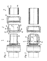
- Fig. 1 shows in a cross-sectional view four workpieces: a fitting 6, a power transmission element 2, a sliding sleeve 4 and a pipe. 8
- the fitting 6 has a profile body having a supporting body 10.
- the support body 10 extends in this example of a base body 12.
- the fitting 6 also has at the transition point from the base body 12 to the support body 10 facing in the axial direction abutment surface 14.
- the profile consists in this particular example of seven annular circumferential grooves, which are delimited by six interposed, annular peripheral dividers.
- the inner peripheral surface of the support body 10 is formed substantially cylindrical, but the support body wall is slightly beveled radially outwardly at the distal end of the base body 12 of the support body 10 in order to make the cross-sectional transition continuous.
- the fitting 6 in Fig. 1 A force transmission element 2 is arranged upstream.
- the force transmission element 2 has a flange section 16 facing the fitting 6 and a transmission section 18.
- a radially inwardly extending contact element 20 On the inner peripheral surface of the flange portion 16 in this embodiment, a radially inwardly extending contact element 20.
- the force transmission element 2 is on the outer peripheral surface of the Flange portion 16 on the front side beyond a chamfer 22 arranged, which can serve as an interaction surface with a pressing tool (not shown).
- the flange portion 16 at its radially inwardly extending region on an axially facing abutment surface 24, on which the end face of a pipe 8 can come into abutment.
- the inner peripheral surface of the flange portion 16 may be formed as a polygon (not shown). In this way, in the interaction with the inner circumferential surface of the flange portion 16 opposite outer peripheral surface of the Fittinggrund stressess 12, on which the force transmission element 2 is to be positioned, an additional safeguard against unwanted rotational movements of the force transmission element 2 relative to the fitting 6 can be achieved.
- the transmission section 18 of the force transmission element 2 has a wall thickness which tapers from the flange section 16 to the wall section which tapers at least in sections, as far as the flange section 16.
- the taper so the wall thickness decrease though by form elements such as in this example at the proximal end of the flange portion 16 of the transfer section 18 locking recess 26 which is annularly circulating, and in this example between the locking recess 26 and the annular end of the retaining portion 28 arranged distal to the flange portion 16 is modified, but tends to remain.
- the taper or wall thickness decrease can thus by an imaginary line (not shown), which by the most radially outwardly portions of the transfer section 18th runs, for example in the manner of an envelope, are represented.
- the wall thickness decrease takes place at least in sections by forming a conical segment surface, which is inclined at an angle of about 15 ° to the central axis 30 of the power transmission element 2.
- three recesses 32 for reducing the contact area are arranged between the holding recess 28 and the distal end.
- the recesses 32 in this example take the form of annular circumferential grooves, but may for example also be formed as a corrugation.
- two openings 34 are arranged in this example, which have a substantially extending in the circumferential direction extent.
- the openings 34 allow an installer to visually inspect the position of the workpieces 2, 4, 6, 8 before and optionally after the pressing operation.
- the openings 34 may of course also have a different shape or be arranged at a different location.
- the number of openings 34 can basically be chosen freely.
- a formation of the inner peripheral surface of the transfer section 18 as a polygon may be provided.
- Fig. 1 a sliding sleeve 4, whose first end has a certain thickness in cross-section, that is, in the cross-sectional view, and whose second end is tapered in cross-section with respect to the first end.
- the outer diameter of the sliding sleeve 4 is at least partially constant over the outer peripheral surface in the axial direction. This means in particular that shape features with a small spatial dimension can be provided, which modify the constancy of the outer diameter. In this particular example, a modification is made in that the tapered end of the sliding sleeve 4 is slightly angled radially outward. But it is also possible to form the sliding sleeve 4 with a constant over the entire axial extent of the sliding sleeve 4 outer diameter.
- a radially inwardly extending latching projection 36 is disposed on the inner peripheral surface of the tapered end, which is annularly circumferential in this example.
- the inner circumferential surface of the sliding sleeve 4 has at least sections of hollow cone segment shape.
- a chamfer 38 is arranged at the non-tapered end, on which a pressing tool (not shown) can begin.
- the installation shown is a composite pipe 8, which comprises three layers 40, 42, 44.
- the inner layer 40 may be made of a cross-linked polyethylene (PEX), the middle layer 42 of a metal such as aluminum, and the outer layer 44 of a particular mechanical stresses resistant or aesthetic Consider sufficient plastic.
- PEX cross-linked polyethylene
- shown composite tube 8 is to be understood only as an example.
- the in Fig. 1 shown installation also comprise a single-layer pipe, for example made of a plastic or a metal or metal material.
- the cross section of the tube 8 is not limited in principle.
- the relevant diameters of the workpieces 2, 4, 6, 8, ie the outer diameter of the support body 10 of the fitting 6 and the inner diameter of the tube 8 or the outer diameter of the tube 8 and the inner diameter of the transfer section 18 of the force transmission element 2 suitable for each other or adapted to each other.
- Fig. 2 shown installation differs from the one in Fig. 1 illustrated in that the force transmission element 2 is fitted onto the fitting 6 and that the fitting 6 engages in the force transmission element 2.
- the flange portion 16 is fixed in this example via a press fit, so a frictional engagement with the fitting body 12 and thereby inhibits an axial movement of the power transmission element 2 and the fitting 6 to each other.
- the facing in the axial direction abutting surface 14 of the fitting 6 is in this example with the arranged on the flange portion 16 contact element 20 in abutment.
- the fitting base body 12 is encompassed essentially by the flange section 16 and the support body 10 essentially by the transmission section 18, with the distal end of the support body 10 protruding from the force transmission element 2 on the transmission section side.
- this embodiment is not mandatory. It is also conceivable that the distal end of the support body 10 and the distal end of the transfer section 18 come to lie approximately in the same perpendicular plane to the central axis 30, or that the distal end of the transfer section 18 even projects beyond the support body 10. So it can be chosen different configurations.
- FIG. 3 The inventive arrangement shown differs from that in Fig. 2 represented in that the sliding sleeve 4 is placed on the transmission section side on the power transmission element 2.
- the arranged on the tapered end of the sliding sleeve 4 locking projection 36 engages in the arranged on the outer peripheral surface of the transfer section 18 holding recess 28 so that in an intermediate position - before the actual pressing operations are initiated - a movement of the sliding sleeve 4 is prevented by the force transmission element 2 down
- the other sections of the inner circumferential surface of the sliding sleeve 4 and the portion of the transfer section 18 located between the holding recess 28 and the distal end are preferably adapted to one another and are at least partially in frictional engagement, with the exception of the depressing depressions 32.
- Fig. 3 thus shows an inventive arrangement for producing a non-detachable workpiece connection, as an installer can purchase commercially, and which only has to be supplemented by a pipe to be compressed 8 in order to make the grouting can.
- Fig. 4 shows those from the Fig. 1 to 3 known installation, in which the tube 8 is inserted into the cavity between the support body 10 of the fitting 6 and the transmission portion 18 of the power transmission element 2. The end face of the tube 8 is pushed up to the stop on the flange portion 16 or arranged on the flange portion 16 contact element 20. By arranged on the transfer section 18 openings 34 (not visible), the installer in the in Fig. 4 shown installation the proper position of the workpieces 2, 4, 6, 8 to each other.
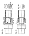
- Fig. 5a The result of the axial pressing process is in Fig. 5a shown.
- the sliding sleeve 4 is moved over the transfer section 18 in the axial direction toward the flange section 16. Due to the inclination of the portion of the inner circumferential surface of the sliding sleeve 4 and the corresponding portions of the outer peripheral surface of the transfer section 18, the dynamics of the pressing movement exerted in the axial direction in this particular embodiment is at least partially deflected into radially inwardly acting pressing forces.
- the transfer section 18 transmits the pressing forces to the tube 8, which is radially inwardly deformed so that the grooves separated by the separating webs on the support body 10 of the Fittings 6 record the displaced material of the tube 8, and thus a positive and positive connection can arise, which ensures the tightness of the permanent workpiece connection.
- a portion of the locking projection 36 may be in contact with a wall of the locking recess 26 so that an axial movement of the sliding sleeve 4 after the axial pressing process is inhibited by the power transmission element 2 down.
- the tapered end of the sliding sleeve 4 protrudes slightly beyond the plane defined by the outer peripheral surface of the flange portion 16 radially outward slightly after the axial pressing operation and thus provides a pressing tool 48 a favorable starting point for a radially inward pressing movement (arrow 50).
- the axial pressing process followed by a radially inward pressing operation whereby a portion of the sliding sleeve 4, in this example, the tapered end of the sliding sleeve 4, is arranged on the inner peripheral surface of the locking projection 36, is formed in the locking recess 26 and thus a stable locking of the Sliding sleeve 4 causes the force transmission element 2.
- This can counteract the fact that the sliding sleeve 4 of the force transmission element 2, for example due to triggered by temperature changes material expansions or contractions again dissolves, which could have leaks result.
- Fig. 6a shows again the four workpieces 2, 4, 6, 8, after both the axial and the radially inward pressing process completed and the permanent workpiece connection are made with it.
- the angled end of the sliding sleeve 4 during the radially inward pressing operation with the outer peripheral surface of the flange portion 16 is formed in a substantially aligned orientation. In this way, the permanent workpiece connection can be made very compact.
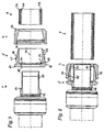
- Fig. 7 shows in a cross-sectional view of four workpieces: a fitting 6, a power transmission element 2 ', a sliding sleeve 4 and a pipe 8. Die das Opera aus Fig. 1 corresponding parts are identified by the same reference numerals.
- the force transmission element 2 ' has a means 28' for temporarily fixing a sliding sleeve.
- the means 28 ' can be designed, for example, as a surface suitable for frictional engagement with the sliding sleeve 4, as an adhesive surface, as a thread or as a depression suitable for form and / or frictional engagement.
- the sliding sleeve in the region of the locking projection 36 may be configured with a corresponding mating thread.
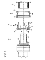
- Fig. 8 shows an inventive arrangement for producing a non-detachable workpiece connection of the in Fig. 7 shown components, such as an installer can purchase commercially, and which only has to be supplemented by a pipe to be compressed 8 in order to make the compression can.
- power transmission element 2 ' may alternatively have no means 28' for temporarily fixing a sliding sleeve.
Landscapes
- Engineering & Computer Science (AREA)
- General Engineering & Computer Science (AREA)
- Mechanical Engineering (AREA)
- Mutual Connection Of Rods And Tubes (AREA)
- Automatic Assembly (AREA)
- Insertion Pins And Rivets (AREA)
Claims (13)
- Ensemble pour la réalisation d'une liaison de pièces non détachable,- avec une ferrure (6), qui est dotée d'un corps de support (10), présentant un profil, et d'un corps de base (12),- avec un élément de transmission de force (2, 2'), qui est doté d'une section de bride (16) et d'une section de transmission (18) présentant une surface périphérique intérieure, sensiblement cylindrique, sachant que l'épaisseur de paroi de la section de transmission (18) s'amincit, au moins par endroits, de l'extrémité la plus proche de la section de bride (16) jusqu'à l'extrémité la plus éloignée de la section de bride (16), et- avec une douille coulissante (4), qui est dotée d'une première extrémité, qui présente une section transversale d'une épaisseur déterminée, et d'une deuxième extrémité de section transversale amincie par rapport à la première extrémité, sachant que, quant à la surface périphérique, extérieure, le diamètre extérieur est constant dans la direction axiale, au moins par sections,
caractérisé en ce que- l'extrémité de la section de transmission (18) de l'élément de transmission de force (2, 2') la plus proche de la section de bride (16) est dotée, sur la surface périphérique extérieure, d'au moins une cavité d'arrêt (26),- sur la surface périphérique intérieure de l'extrémité amincie de la douille coulissante (4), est agencée au moins une saillie d'arrêt (36), qui s'enclenche radialement, vers l'intérieur, et- l'élément de transmission de force (2, 2') enveloppe le corps de support (10) et, au moins partiellement, le corps de base (12). - Ensemble selon la revendication 1, caractérisée en ce que,- sur la surface périphérique externe, entre la cavité d'arrêt (26) et l'extrémité distale de la section de transmission (18), est agencé un organe de fixation (28'), destiné à la fixation temporaire d'une douille coulissante,- la douille coulissante (4) est glissée, avec l'extrémité amincie, sur la section de transmission (18), jusqu'à ce que la douille coulissante (4) se trouve en contact avec l'organe (28') destiné à la fixation temporaire d'une douille coulissante, et- la douille coulissante (4) est fixée temporairement sur la section de transmission par l'organe (28') destiné à la fixation temporaire d'une douille coulissante.
- Ensemble selon l'une des revendications 1 à 2, caractérisé en ce que,- sur la surface périphérique, extérieure, entre la cavité d'arrêt (26) et l'extrémité distale de la section de transmission (18), est agencée au moins une cavité d'arrêt (28, 28') et- la douille coulissante (4) est poussée, avec l'extrémité amincie, si loin, sur la section de transmission (18), que la saillie d'arrêt (36) s'engage dans la cavité d'arrêt (28, 28').
- Ensemble selon l'une des revendications 1 à 3, caractérisé en ce que la section de bride (16) est fixée au corps de base (12), sachant que, tout particulièrement, un élément de contact (20) de la section de bride (16) porte contre une surface d'about (14) du corps de base (12), qui est orientée dans la direction axiale.
- Procédé pour la réalisation d'une liaison de pièces non détachable, entre une ferrure (6), un tube (8), un l'élément de transmission de force (2, 2') et une douille coulissante (4),- dans lequel l'élément de transmission de force (2, 2') est pressé avec la douille coulissante (4) au moins prévue, qui est glissée, au moins partiellement sur lui, de sorte que le tube (8) soit surmoulé sur un corps de support (10) de la ferrure (6),
caractérisé en ce que,- le processus de pression axial est suivi d'un processus de compression radial, au moyen duquel la douille coulissante (4) est repoussée, au moins par sections, dans l'élément de transmission de force (2, 2'), de sorte qu'un déplacement axial de la douille coulissante (4) par rapport à l'élément de transmission de force (2, 2') soit entravé après le processus de compression. - Procédé selon la revendication 5, dans lequel on utilise une ferrure (6), qui est pourvue d'un corps de support (10), doté d'un profil, et d'un corps de base (12), sachant que le tube (8) est repoussé dans le profil du corps de support (10).
- Procédé selon revendication 5 ou 6, dans lequel on utilise un élément de transmission de force (2, 2'), qui est doté d'une section de bride (16) et d'une section de transmission (18), sachant que l'extrémité de la section de transmission (18), la plus proche de la section de bride (16) est dotée d'au moins une cavité d'arrêt (26), et dans lequel la douille coulissante (4) est repoussée, au moins par sections, dans la cavité d'arrêt (26).
- Procédé selon la revendication 7, dans lequel on utilise une douille coulissante (4), qui est dotée d'une première extrémité, qui présente une section transversale d'une épaisseur déterminée, et d'une deuxième extrémité de section transversale amincie par rapport à la première extrémité, sachant que, sur la surface périphérique, intérieure de l'extrémité amincie, est agencée au moins une saillie d'arrêt (36), qui s'enclenche radialement, vers l'intérieur
- Procédé selon l'une des revendications 7 à 8, caractérisé en ce que- l'élément de transmission de force (2, 2') est doté, sur la surface périphérique, extérieure, entre la cavité d'arrêt (26) et l'extrémité distale de la section de transmission (18), d'au moins un organe de fixation (28'), destiné à la fixation temporaire d'une douille coulissante,- la douille coulissante (4) est glissée, avec son extrémité amincie, sur la section de transmission (18) jusqu'à ce que ladite douille coulissante (4) porte contre l'organe (28'), destiné à la fixation temporaire d'une douille coulissante, et- la douille coulissante (4) est fixée par l'organe (28') destiné à la fixation temporaire d'une douille coulissante.
- Procédé selon l'une des revendications 7 à 9, caractérisé en ce que- l'élément de transmission de force (2, 2') est doté, sur la surface périphérique, extérieure, entre la cavité d'arrêt (26) et l'extrémité distale de la section de transmission (18), d'au moins une cavité de retenue (28, 28'), et- la douille coulissante (4) est poussée, avec son extrémité amincie, sur la section de transmission (18), jusqu'à ce que la saillie d'arrêt (36) s'engage dans la cavité de retenue (28, 28'), dans une position intermédiaire.
- Procédé selon l'une des revendications 7 à 10, dans lequel on utilise une douille coulissante (4), dont l'extrémité amincie est coudé vers l'extérieur, dans la direction radiale, et dans lequel, au cours du processus de compression radial, l'extrémité coudée est déformée dans la direction d'un meilleur alignement avec la surface périphérique de la section de transmission (18), extérieure.
- Procédé selon l'une des revendications 7 à 11, dans lequel l'élément de transmission de force (2, 2') et la douille coulissante (4), glissée sur lui, sont pressés dans la direction axiale, sachant que la saillie d'arrêt (36) est amenée dans une position opposée à la cavité d'arrêt (26).
- Procédé selon l'une des revendications 7 à 12, dans lequel le processus de pression axial est suivi d'un processus de compression, dans lequel la saillie d'arrêt (36) est enclenchée dans la cavité d'arrêt (26).
Priority Applications (1)
| Application Number | Priority Date | Filing Date | Title |
|---|---|---|---|
| PL09780255T PL2304301T3 (pl) | 2008-07-07 | 2009-07-07 | Układ ze złączką rurową, elementem do przenoszenia siły i tuleją luźną oraz sposób wytwarzania nierozłącznego połączenia obrabianych elementów |
Applications Claiming Priority (3)
| Application Number | Priority Date | Filing Date | Title |
|---|---|---|---|
| DE102008031554 | 2008-07-07 | ||
| DE102008039446.7A DE102008039446B4 (de) | 2008-07-07 | 2008-08-25 | Anordnung sowie Verfahren zur Herstellung einer unlösbaren Werkstückverbindung |
| PCT/EP2009/058600 WO2010003951A1 (fr) | 2008-07-07 | 2009-07-07 | Elément de transmission de force, coulisseau, ensemble et procédé de fabrication d’une liaison de pièces non détachable |
Publications (2)
| Publication Number | Publication Date |
|---|---|
| EP2304301A1 EP2304301A1 (fr) | 2011-04-06 |
| EP2304301B1 true EP2304301B1 (fr) | 2013-08-28 |
Family
ID=41412847
Family Applications (1)
| Application Number | Title | Priority Date | Filing Date |
|---|---|---|---|
| EP20090780255 Active EP2304301B1 (fr) | 2008-07-07 | 2009-07-07 | Ensemble avec une ferrure, un elément de transmission de force et une bague coulissante, ensemble et procédé de fabrication d'une liaison de pièces non détachable |
Country Status (13)
| Country | Link |
|---|---|
| US (2) | US8745843B2 (fr) |
| EP (1) | EP2304301B1 (fr) |
| CN (1) | CN102084169B (fr) |
| AU (1) | AU2009268092B2 (fr) |
| CA (1) | CA2729290C (fr) |
| DE (2) | DE102008039446B4 (fr) |
| DK (1) | DK2304301T3 (fr) |
| ES (1) | ES2435571T3 (fr) |
| MX (1) | MX2011000157A (fr) |
| PL (1) | PL2304301T3 (fr) |
| PT (2) | PT2304301E (fr) |
| RU (1) | RU2446341C1 (fr) |
| WO (1) | WO2010003951A1 (fr) |
Families Citing this family (24)
| Publication number | Priority date | Publication date | Assignee | Title |
|---|---|---|---|---|
| US8888140B2 (en) | 2009-02-18 | 2014-11-18 | Parker-Hannifin Corporation | Hose fitting |
| EP2643624B1 (fr) * | 2010-11-24 | 2016-10-19 | Raccords et Plastiques Nicoll | Emmanchement à la presse |
| DE202011000061U1 (de) * | 2011-01-12 | 2012-04-17 | Gebrüder Beul GmbH & Co KG | Anschlussverbinder |
| RU2484353C1 (ru) * | 2012-04-17 | 2013-06-10 | Общество С Ограниченной Ответственностью "Группа Полимертепло" | Узел соединения полимерной трубы |
| PT2677224T (pt) * | 2012-06-20 | 2016-07-15 | Fischer Georg Jrg Ag | União de aperto para tubos |
| DE102012110086A1 (de) | 2012-10-23 | 2014-04-24 | Viega Gmbh & Co. Kg | Hülse für unlösbare Verbindung, Verfahren zur Herstellung einer Hülse und System mit einer Hülse |
| JP5799326B2 (ja) * | 2013-08-30 | 2015-10-21 | 株式会社トヨックス | 管継手 |
| JP5849261B2 (ja) * | 2013-08-30 | 2016-01-27 | 株式会社トヨックス | 管継手 |
| FR3027091B1 (fr) * | 2014-10-08 | 2017-04-07 | Air Liquide | Raccord a sertir sur au moins un tuyau, ensemble de tuyaux comprenant un tel raccord et procede d'assemblage de tuyau a un tel raccord |
| DE102015103228B4 (de) * | 2015-03-05 | 2018-03-22 | Viega Technology Gmbh & Co. Kg | Presshülse, Pressfitting und Verwendung des Pressfittings oder der Presshülse |
| US9982813B2 (en) * | 2015-03-27 | 2018-05-29 | Designed Metal Connections, Inc. | Swage fitting |
| CN105508793A (zh) * | 2016-01-26 | 2016-04-20 | 黄龙珠 | 一种用于聚合物管道与金属接头的连接装置 |
| US11541581B2 (en) | 2016-09-02 | 2023-01-03 | Zurn Industries, Llc | Injection molded cold-expansion compression collar |
| US11543065B2 (en) | 2016-09-02 | 2023-01-03 | Zurn Industries, Llc | Extruded cold-expansion compression collar |
| CA2977581A1 (fr) | 2016-09-02 | 2018-03-02 | Zurn Industries, Llc | Collier de compression a dilatation a froid moule par injection |
| DE102016117830A1 (de) | 2016-09-21 | 2018-03-22 | Voss Automotive Gmbh | Steckverbinderanordnung für Medienleitungen sowie Verfahren zum Verbinden von Medienleitungen |
| US11054076B2 (en) | 2016-11-04 | 2021-07-06 | Zurn Industries, Llc | Reinforcing ring with sleeve |
| CN109422228B (zh) * | 2017-08-25 | 2021-01-29 | 系统科技公司 | 化学品自动供给装置以及化学品自动供给装置的控制方法 |
| DE102017009942A1 (de) * | 2017-10-25 | 2019-04-25 | Hydac Fluidtechnik Gmbh | Kupplungseinrichtung |
| WO2019148075A1 (fr) * | 2018-01-29 | 2019-08-01 | Tylok International, Inc. | Raccord serti axial |
| CN108443621A (zh) * | 2018-03-22 | 2018-08-24 | 辐基斯(青岛)复合材料管道有限公司 | 一种柔性复合管用管接头及其装配方法 |
| US11398719B2 (en) | 2019-04-30 | 2022-07-26 | Eaton Intelligent Power Limited | Press fit condulet devices, assemblies systems and methods for electrical raceway fabrication |
| US11333282B2 (en) | 2019-11-05 | 2022-05-17 | Diality Inc. | Locking connector |
| US11996683B2 (en) | 2020-10-19 | 2024-05-28 | Eaton Intelligent Power Limited | Compressible condulet devices, assemblies, systems and methods for electrical raceway fabrication |
Family Cites Families (43)
| Publication number | Priority date | Publication date | Assignee | Title |
|---|---|---|---|---|
| US191716A (en) * | 1877-06-05 | Improvement in engine-frames | ||
| US2733941A (en) * | 1956-02-07 | Flexible hose couplings | ||
| US2733940A (en) * | 1956-02-07 | millar | ||
| US2278239A (en) * | 1939-09-26 | 1942-03-31 | Cincinnati Ball Crank Co | Hose coupling |
| US3003792A (en) * | 1959-04-14 | 1961-10-10 | Robert A Gilmour | Flexible hose coupler with rotational cam |
| GB1062991A (en) * | 1965-01-06 | 1967-03-22 | Superflexit | Improvements in end fittings for flexible conduits |
| US3423109A (en) * | 1966-03-30 | 1969-01-21 | Stratoflex Inc | Hose fitting |
| US3537729A (en) * | 1967-12-28 | 1970-11-03 | Sun Oil Co | Expansion joint for pipe |
| US3533649A (en) | 1969-01-30 | 1970-10-13 | Genova Products | Pipe fitting |
| US3612584A (en) | 1969-10-16 | 1971-10-12 | Taylor Industries | Temperature compensated fluid coupling |
| US4033614A (en) | 1976-03-01 | 1977-07-05 | Ideal Industries, Inc. | Conduit fitting |
| US4482174A (en) | 1980-09-15 | 1984-11-13 | Lokring | Apparatus and method for making a tube connection |
| US4412693A (en) * | 1981-07-31 | 1983-11-01 | Sergio Campanini | Swivel hose coupling with threaded nipple |
| IL72279A (en) | 1983-07-19 | 1988-11-30 | Pfister Juerg | Pipe coupling device |
| US4626001A (en) * | 1984-04-16 | 1986-12-02 | The Deutsch Company Metal Components Division | Fluid fitting with high temperature capabilities |
| CN1014263B (zh) | 1985-06-20 | 1991-10-09 | 多伊奇公司金属部件科 | 具有高温工作能力的流体管接头 |
| US5037142A (en) * | 1989-07-24 | 1991-08-06 | General Motors Corporation | Fluid line support and connector |
| US5326137A (en) * | 1991-09-24 | 1994-07-05 | Perfection Corporation | Gas riser apparatus and method |
| DE9307262U1 (de) * | 1993-05-13 | 1993-07-15 | Hackforth GmbH & Co KG, 4690 Herne | Schiebehülsen-Verbindung für Kunststoffrohre |
| DE4430114C2 (de) * | 1994-07-19 | 1997-12-04 | Friedhelm Ramspott Metall Und | Anschlußstück für einen Kunststoffschlauch einer Badezimmer-Handbrause |
| US5590914A (en) * | 1995-01-05 | 1997-01-07 | Perfection Corporation | Field assembled gas riser |
| DE29503019U1 (de) | 1995-02-23 | 1995-04-06 | Fa. Franz Viegener Ii, 57439 Attendorn | Abdichtende Verbindung eines Kunststoffrohres mit einem aus Metall gefertigten Anschlußstück |
| DE19512986C1 (de) | 1995-04-06 | 1997-01-02 | Gemi Metallwarenfabrik Gmbh & | Schlauchbefestigungssystem sowie Verfahren zu seiner Montage |
| US5558375A (en) * | 1995-07-10 | 1996-09-24 | Deere & Company | Quick attach, reusable hose fittings |
| DE19536598C2 (de) | 1995-09-19 | 2000-01-13 | Mannesmann Ag | Rohrverbindung |
| KR980008820U (ko) | 1996-07-10 | 1998-04-30 | 박강훈 | 합성수지 호오스 연결구 |
| IT242911Y1 (it) | 1997-05-13 | 2002-02-04 | Flextubo Hydro S R L | Dispositivo di attacco per un tubo flessibile ad alta pressione. |
| US6254144B1 (en) * | 1998-12-02 | 2001-07-03 | Kilgore Manufacturing | Hose coupling |
| DE10035791A1 (de) * | 1999-07-26 | 2001-03-01 | Voss Armaturen | Steckarmatur zum schnellen und lösbaren Anschluß von Druckmittel-Leitungen |
| US6450553B1 (en) * | 1999-11-05 | 2002-09-17 | Mechl Llc | Axial swage fitting for large bore pipes and tubes |
| ITPR20000009A1 (it) * | 2000-02-04 | 2001-08-04 | Mac Tubi S P A | Dispositivo di giunzione per tubi flessibili |
| RU2208737C2 (ru) * | 2001-01-12 | 2003-07-20 | Зильберберг Владимир Элюкимович | Неразъемное соединение концевой арматуры с рукавом высокого давления |
| DE10133183C1 (de) * | 2001-07-07 | 2002-11-14 | Manfred Reckzeh | Rohrpresskupplung mit Presshülse sowie Verpressungsverfahren |
| EP1288554A1 (fr) | 2001-08-28 | 2003-03-05 | Polypress Rohrsysteme GmbH | Dispositif de connexion pour un tube |
| US6758386B2 (en) | 2001-09-18 | 2004-07-06 | The Boeing Company | Method of joining ceramic matrix composites and metals |
| US7234732B2 (en) | 2003-09-30 | 2007-06-26 | Wcm Industries, Inc. | Pipe coupling for joining pipes of varying diameters |
| DE202004000031U1 (de) * | 2004-01-02 | 2004-07-01 | Reckzeh, Manfred | Rohrpresskupplung |
| CN2743660Y (zh) | 2004-10-08 | 2005-11-30 | 程伟良 | 内插挤压式管接头 |
| CN2839784Y (zh) | 2005-08-23 | 2006-11-22 | 浙江金德阀门有限公司 | 卡压式铝塑复合管管件 |
| DE202006001908U1 (de) * | 2006-02-07 | 2006-04-13 | Rebersek, Vinko | Rohrverbindung für fluid- und gasführende Installationen |
| CN2888233Y (zh) | 2006-04-10 | 2007-04-11 | 河北省电焊机股份有限公司 | 一种高压塑料管道用快速接头 |
| GB0619884D0 (en) | 2006-10-07 | 2006-11-15 | Aflex Hose Ltd | Hose fitting |
| DE102008010084B4 (de) * | 2008-02-19 | 2016-12-29 | Viega Gmbh & Co. Kg | Übertragungselement für axial zu verpressende Werkstückverbindungen sowie Anordnung zur Herstellung einer unlösbaren Verbindung |
-
2008
- 2008-08-25 DE DE102008039446.7A patent/DE102008039446B4/de active Active
- 2008-09-16 DE DE102008047544.0A patent/DE102008047544B4/de active Active
-
2009
- 2009-07-07 US US13/002,741 patent/US8745843B2/en active Active
- 2009-07-07 CN CN200980126213.6A patent/CN102084169B/zh active Active
- 2009-07-07 EP EP20090780255 patent/EP2304301B1/fr active Active
- 2009-07-07 WO PCT/EP2009/058600 patent/WO2010003951A1/fr not_active Ceased
- 2009-07-07 MX MX2011000157A patent/MX2011000157A/es active IP Right Grant
- 2009-07-07 DK DK09780255T patent/DK2304301T3/da active
- 2009-07-07 CA CA2729290A patent/CA2729290C/fr active Active
- 2009-07-07 AU AU2009268092A patent/AU2009268092B2/en active Active
- 2009-07-07 ES ES09780255T patent/ES2435571T3/es active Active
- 2009-07-07 RU RU2011104071/06A patent/RU2446341C1/ru active
- 2009-07-07 PT PT97802557T patent/PT2304301E/pt unknown
- 2009-07-07 PL PL09780255T patent/PL2304301T3/pl unknown
- 2009-09-15 PT PT09783022T patent/PT2334967E/pt unknown
- 2009-09-15 US US13/063,880 patent/US9004541B2/en not_active Expired - Fee Related
Also Published As
| Publication number | Publication date |
|---|---|
| US9004541B2 (en) | 2015-04-14 |
| DE102008039446A1 (de) | 2010-01-14 |
| US8745843B2 (en) | 2014-06-10 |
| CN102084169B (zh) | 2014-12-17 |
| DK2304301T3 (da) | 2013-11-25 |
| ES2435571T3 (es) | 2013-12-20 |
| DE102008047544B4 (de) | 2018-01-25 |
| CA2729290C (fr) | 2013-12-31 |
| CN102084169A (zh) | 2011-06-01 |
| AU2009268092B2 (en) | 2013-08-22 |
| DE102008039446B4 (de) | 2015-12-17 |
| WO2010003951A1 (fr) | 2010-01-14 |
| RU2446341C1 (ru) | 2012-03-27 |
| EP2304301A1 (fr) | 2011-04-06 |
| PT2334967E (pt) | 2015-02-27 |
| PT2304301E (pt) | 2013-11-21 |
| MX2011000157A (es) | 2011-03-01 |
| US20110169262A1 (en) | 2011-07-14 |
| DE102008047544A1 (de) | 2010-01-14 |
| AU2009268092A1 (en) | 2010-01-14 |
| CA2729290A1 (fr) | 2010-01-14 |
| PL2304301T3 (pl) | 2014-01-31 |
| US20110289761A1 (en) | 2011-12-01 |
Similar Documents
| Publication | Publication Date | Title |
|---|---|---|
| DE102008039446B4 (de) | Anordnung sowie Verfahren zur Herstellung einer unlösbaren Werkstückverbindung | |
| DE2911708C2 (de) | Rohrverbindungsanordnung, insbesondere für Gasrohrleitungsnetze oder dergleichen, und Verfahren und Vorrichtung zur Herstellung von derartigen Rohrverbindungsanordnungen | |
| EP2809463B1 (fr) | Tête d'expansion pour outils d'élargissement, outil d'expansion comprenant ladite tête et utilisation de ladite tête d'expansion et dudit outil d'expansion | |
| DE102008024360B4 (de) | Rohrpresskupplung, insbesondere für Mehrschichtverbundrohre, sowie Verpressungsverfahren | |
| EP0845092A1 (fr) | Systeme de raccordement haute pression | |
| DE19639794C2 (de) | Schlauchfassung und Verfahren zu deren Herstellung | |
| EP0539844B1 (fr) | Raccord de serrage pour tuyaux rigides ou flexibles en matière polymère | |
| EP1151220B1 (fr) | Accouplement de tuyaux destine a des tuyaux plastique | |
| EP3894711A1 (fr) | Cheville à expansion | |
| EP2334967B1 (fr) | Raccord composite en deux pièces | |
| DE4325349C2 (de) | Verbindungsvorrichtung | |
| DE19828141A1 (de) | Rohrverbindung, insbesondere für Kunststoffrohre bzw. Verbundrohre | |
| EP2886923A1 (fr) | Racord de tuyau pour des conduites de tuyaux hydrauliques avec joint périphérique | |
| EP1700059B1 (fr) | Raccord a compression pour tube ou tuyau | |
| WO2003011503A1 (fr) | Element d'ecartement pour une pince de serrage et pince de serrage | |
| EP0985867A1 (fr) | Tuyau ondulé en plastique et combinaison de ce tuyau avec un manchon | |
| DE9412445U1 (de) | Unlösbare Rohrverbindung | |
| DE2725579C3 (de) | Vorrichtung zum Verbinden zweier Rohrenden | |
| EP1921364A1 (fr) | Raccord de serrage pour un tuyau, en particulier tuyau sanitaire et/ou de chauffage | |
| EP2505897A1 (fr) | Raccord de sertissage pour tuyaux en plastique | |
| DE29818534U1 (de) | Verbindung für Rohr- und/oder Schlauchleitungen | |
| DE10331381A1 (de) | Pressverbindung und Stützhülse für eine Pressverbindung | |
| DE2738454C3 (de) | Lösbare Muffensteckverbindung | |
| DE29719536U1 (de) | Preßverbindung | |
| EP1241393B1 (fr) | Raccord de tuyauterie |
Legal Events
| Date | Code | Title | Description |
|---|---|---|---|
| PUAI | Public reference made under article 153(3) epc to a published international application that has entered the european phase |
Free format text: ORIGINAL CODE: 0009012 |
|
| 17P | Request for examination filed |
Effective date: 20101221 |
|
| AK | Designated contracting states |
Kind code of ref document: A1 Designated state(s): AT BE BG CH CY CZ DE DK EE ES FI FR GB GR HR HU IE IS IT LI LT LU LV MC MK MT NL NO PL PT RO SE SI SK SM TR |
|
| AX | Request for extension of the european patent |
Extension state: AL BA RS |
|
| DAX | Request for extension of the european patent (deleted) | ||
| 17Q | First examination report despatched |
Effective date: 20120823 |
|
| RIC1 | Information provided on ipc code assigned before grant |
Ipc: F16L 33/207 20060101ALI20121221BHEP Ipc: F16L 37/138 20060101ALI20121221BHEP Ipc: F16L 13/14 20060101ALI20121221BHEP Ipc: F16L 33/22 20060101AFI20121221BHEP |
|
| GRAP | Despatch of communication of intention to grant a patent |
Free format text: ORIGINAL CODE: EPIDOSNIGR1 |
|
| GRAS | Grant fee paid |
Free format text: ORIGINAL CODE: EPIDOSNIGR3 |
|
| GRAA | (expected) grant |
Free format text: ORIGINAL CODE: 0009210 |
|
| AK | Designated contracting states |
Kind code of ref document: B1 Designated state(s): AT BE BG CH CY CZ DE DK EE ES FI FR GB GR HR HU IE IS IT LI LT LU LV MC MK MT NL NO PL PT RO SE SI SK SM TR |
|
| REG | Reference to a national code |
Ref country code: GB Ref legal event code: FG4D Free format text: NOT ENGLISH |
|
| REG | Reference to a national code |
Ref country code: CH Ref legal event code: EP |
|
| REG | Reference to a national code |
Ref country code: AT Ref legal event code: REF Ref document number: 629558 Country of ref document: AT Kind code of ref document: T Effective date: 20130915 |
|
| REG | Reference to a national code |
Ref country code: IE Ref legal event code: FG4D Free format text: LANGUAGE OF EP DOCUMENT: GERMAN |
|
| REG | Reference to a national code |
Ref country code: DE Ref legal event code: R096 Ref document number: 502009007909 Country of ref document: DE Effective date: 20131024 |
|
| REG | Reference to a national code |
Ref country code: CH Ref legal event code: NV Representative=s name: TROESCH SCHEIDEGGER WERNER AG, CH |
|
| REG | Reference to a national code |
Ref country code: PT Ref legal event code: SC4A Free format text: AVAILABILITY OF NATIONAL TRANSLATION Effective date: 20131114 |
|
| REG | Reference to a national code |
Ref country code: DK Ref legal event code: T3 Effective date: 20131119 |
|
| REG | Reference to a national code |
Ref country code: SE Ref legal event code: TRGR |
|
| REG | Reference to a national code |
Ref country code: NL Ref legal event code: T3 |
|
| REG | Reference to a national code |
Ref country code: ES Ref legal event code: FG2A Ref document number: 2435571 Country of ref document: ES Kind code of ref document: T3 Effective date: 20131220 |
|
| REG | Reference to a national code |
Ref country code: LT Ref legal event code: MG4D |
|
| PG25 | Lapsed in a contracting state [announced via postgrant information from national office to epo] |
Ref country code: LT Free format text: LAPSE BECAUSE OF FAILURE TO SUBMIT A TRANSLATION OF THE DESCRIPTION OR TO PAY THE FEE WITHIN THE PRESCRIBED TIME-LIMIT Effective date: 20130828 Ref country code: HR Free format text: LAPSE BECAUSE OF FAILURE TO SUBMIT A TRANSLATION OF THE DESCRIPTION OR TO PAY THE FEE WITHIN THE PRESCRIBED TIME-LIMIT Effective date: 20130828 Ref country code: CY Free format text: LAPSE BECAUSE OF FAILURE TO SUBMIT A TRANSLATION OF THE DESCRIPTION OR TO PAY THE FEE WITHIN THE PRESCRIBED TIME-LIMIT Effective date: 20130710 Ref country code: NO Free format text: LAPSE BECAUSE OF FAILURE TO SUBMIT A TRANSLATION OF THE DESCRIPTION OR TO PAY THE FEE WITHIN THE PRESCRIBED TIME-LIMIT Effective date: 20131128 Ref country code: IS Free format text: LAPSE BECAUSE OF FAILURE TO SUBMIT A TRANSLATION OF THE DESCRIPTION OR TO PAY THE FEE WITHIN THE PRESCRIBED TIME-LIMIT Effective date: 20131228 |
|
| REG | Reference to a national code |
Ref country code: PL Ref legal event code: T3 |
|
| PG25 | Lapsed in a contracting state [announced via postgrant information from national office to epo] |
Ref country code: SI Free format text: LAPSE BECAUSE OF FAILURE TO SUBMIT A TRANSLATION OF THE DESCRIPTION OR TO PAY THE FEE WITHIN THE PRESCRIBED TIME-LIMIT Effective date: 20130828 Ref country code: LV Free format text: LAPSE BECAUSE OF FAILURE TO SUBMIT A TRANSLATION OF THE DESCRIPTION OR TO PAY THE FEE WITHIN THE PRESCRIBED TIME-LIMIT Effective date: 20130828 Ref country code: GR Free format text: LAPSE BECAUSE OF FAILURE TO SUBMIT A TRANSLATION OF THE DESCRIPTION OR TO PAY THE FEE WITHIN THE PRESCRIBED TIME-LIMIT Effective date: 20131129 |
|
| REG | Reference to a national code |
Ref country code: SK Ref legal event code: T3 Ref document number: E 15385 Country of ref document: SK |
|
| PG25 | Lapsed in a contracting state [announced via postgrant information from national office to epo] |
Ref country code: CY Free format text: LAPSE BECAUSE OF FAILURE TO SUBMIT A TRANSLATION OF THE DESCRIPTION OR TO PAY THE FEE WITHIN THE PRESCRIBED TIME-LIMIT Effective date: 20130828 |
|
| PG25 | Lapsed in a contracting state [announced via postgrant information from national office to epo] |
Ref country code: EE Free format text: LAPSE BECAUSE OF FAILURE TO SUBMIT A TRANSLATION OF THE DESCRIPTION OR TO PAY THE FEE WITHIN THE PRESCRIBED TIME-LIMIT Effective date: 20130828 Ref country code: RO Free format text: LAPSE BECAUSE OF FAILURE TO SUBMIT A TRANSLATION OF THE DESCRIPTION OR TO PAY THE FEE WITHIN THE PRESCRIBED TIME-LIMIT Effective date: 20130828 |
|
| REG | Reference to a national code |
Ref country code: DE Ref legal event code: R097 Ref document number: 502009007909 Country of ref document: DE |
|
| PLBE | No opposition filed within time limit |
Free format text: ORIGINAL CODE: 0009261 |
|
| STAA | Information on the status of an ep patent application or granted ep patent |
Free format text: STATUS: NO OPPOSITION FILED WITHIN TIME LIMIT |
|
| 26N | No opposition filed |
Effective date: 20140530 |
|
| REG | Reference to a national code |
Ref country code: DE Ref legal event code: R097 Ref document number: 502009007909 Country of ref document: DE Effective date: 20140530 |
|
| REG | Reference to a national code |
Ref country code: HU Ref legal event code: AG4A Ref document number: E020242 Country of ref document: HU |
|
| PG25 | Lapsed in a contracting state [announced via postgrant information from national office to epo] |
Ref country code: LU Free format text: LAPSE BECAUSE OF FAILURE TO SUBMIT A TRANSLATION OF THE DESCRIPTION OR TO PAY THE FEE WITHIN THE PRESCRIBED TIME-LIMIT Effective date: 20140707 |
|
| PG25 | Lapsed in a contracting state [announced via postgrant information from national office to epo] |
Ref country code: MC Free format text: LAPSE BECAUSE OF FAILURE TO SUBMIT A TRANSLATION OF THE DESCRIPTION OR TO PAY THE FEE WITHIN THE PRESCRIBED TIME-LIMIT Effective date: 20130828 Ref country code: SM Free format text: LAPSE BECAUSE OF FAILURE TO SUBMIT A TRANSLATION OF THE DESCRIPTION OR TO PAY THE FEE WITHIN THE PRESCRIBED TIME-LIMIT Effective date: 20130828 |
|
| PG25 | Lapsed in a contracting state [announced via postgrant information from national office to epo] |
Ref country code: BG Free format text: LAPSE BECAUSE OF FAILURE TO SUBMIT A TRANSLATION OF THE DESCRIPTION OR TO PAY THE FEE WITHIN THE PRESCRIBED TIME-LIMIT Effective date: 20130828 Ref country code: MT Free format text: LAPSE BECAUSE OF FAILURE TO SUBMIT A TRANSLATION OF THE DESCRIPTION OR TO PAY THE FEE WITHIN THE PRESCRIBED TIME-LIMIT Effective date: 20130828 |
|
| REG | Reference to a national code |
Ref country code: FR Ref legal event code: PLFP Year of fee payment: 8 |
|
| REG | Reference to a national code |
Ref country code: DE Ref legal event code: R082 Ref document number: 502009007909 Country of ref document: DE Representative=s name: COHAUSZ & FLORACK PATENT- UND RECHTSANWAELTE P, DE Ref country code: DE Ref legal event code: R081 Ref document number: 502009007909 Country of ref document: DE Owner name: VIEGA TECHNOLOGY GMBH & CO. KG, DE Free format text: FORMER OWNER: VIEGA GMBH & CO. KG, 57439 ATTENDORN, DE |
|
| REG | Reference to a national code |
Ref country code: AT Ref legal event code: PC Ref document number: 629558 Country of ref document: AT Kind code of ref document: T Owner name: VIEGA TECHNOLOGY GMBH & CO. KG, DE Effective date: 20170512 |
|
| REG | Reference to a national code |
Ref country code: HU Ref legal event code: FH1C Free format text: FORMER REPRESENTATIVE(S): DR. JAKABNE MOLNAR JUDIT, SBGK SZABADALMI UEGYVIVOEI IRODA, HU Representative=s name: SBGK SZABADALMI UEGYVIVOEI IRODA, HU Ref country code: HU Ref legal event code: GB9C Owner name: VIEGA TECHNOLOGY GMBH & CO. KG, DE Free format text: FORMER OWNER(S): VIEGA GMBH & CO. KG, DE |
|
| REG | Reference to a national code |
Ref country code: NL Ref legal event code: PD Owner name: VIEGA TECHNOLOGY GMBH & CO. KG; DE Free format text: DETAILS ASSIGNMENT: CHANGE OF OWNER(S), ASSIGNMENT; FORMER OWNER NAME: VIEGA GMBH & CO. KG Effective date: 20170412 |
|
| REG | Reference to a national code |
Ref country code: FR Ref legal event code: PLFP Year of fee payment: 9 |
|
| REG | Reference to a national code |
Ref country code: GB Ref legal event code: 732E Free format text: REGISTERED BETWEEN 20170706 AND 20170715 Ref country code: SK Ref legal event code: PC4A Ref document number: E 15385 Country of ref document: SK Owner name: VIEGA TECHNOLOGY GMBH & CO. KG, ATTENDORN, DE Free format text: FORMER OWNER: VIEGA GMBH & CO. KG, ATTENDORN, DE Effective date: 20161230 |
|
| REG | Reference to a national code |
Ref country code: ES Ref legal event code: PC2A Owner name: VIEGA TECHNOLOGY GMBH & CO. KG Effective date: 20170925 |
|
| REG | Reference to a national code |
Ref country code: FR Ref legal event code: TP Owner name: VIEGA TECHNOLOGY GMBH & CO. KG, DE Effective date: 20171013 |
|
| REG | Reference to a national code |
Ref country code: CH Ref legal event code: PUE Owner name: VIEGA TECHNOLOGY GMBH AND CO. KG, DE Free format text: FORMER OWNER: VIEGA GMBH AND CO. KG, DE |
|
| PG25 | Lapsed in a contracting state [announced via postgrant information from national office to epo] |
Ref country code: MK Free format text: LAPSE BECAUSE OF FAILURE TO SUBMIT A TRANSLATION OF THE DESCRIPTION OR TO PAY THE FEE WITHIN THE PRESCRIBED TIME-LIMIT Effective date: 20130828 |
|
| REG | Reference to a national code |
Ref country code: FR Ref legal event code: PLFP Year of fee payment: 10 |
|
| PGFP | Annual fee paid to national office [announced via postgrant information from national office to epo] |
Ref country code: PT Payment date: 20230626 Year of fee payment: 15 Ref country code: CZ Payment date: 20230601 Year of fee payment: 15 |
|
| PGFP | Annual fee paid to national office [announced via postgrant information from national office to epo] |
Ref country code: TR Payment date: 20230606 Year of fee payment: 15 Ref country code: SK Payment date: 20230601 Year of fee payment: 15 |
|
| PGFP | Annual fee paid to national office [announced via postgrant information from national office to epo] |
Ref country code: IE Payment date: 20230726 Year of fee payment: 15 Ref country code: ES Payment date: 20230825 Year of fee payment: 15 |
|
| PGFP | Annual fee paid to national office [announced via postgrant information from national office to epo] |
Ref country code: SE Payment date: 20230727 Year of fee payment: 15 Ref country code: HU Payment date: 20230602 Year of fee payment: 15 Ref country code: BE Payment date: 20230725 Year of fee payment: 15 |
|
| PG25 | Lapsed in a contracting state [announced via postgrant information from national office to epo] |
Ref country code: CZ Free format text: LAPSE BECAUSE OF NON-PAYMENT OF DUE FEES Effective date: 20240707 |
|
| PG25 | Lapsed in a contracting state [announced via postgrant information from national office to epo] |
Ref country code: CZ Free format text: LAPSE BECAUSE OF NON-PAYMENT OF DUE FEES Effective date: 20240707 |
|
| REG | Reference to a national code |
Ref country code: SK Ref legal event code: MM4A Ref document number: E 15385 Country of ref document: SK Effective date: 20240707 |
|
| REG | Reference to a national code |
Ref country code: SE Ref legal event code: EUG |
|
| PG25 | Lapsed in a contracting state [announced via postgrant information from national office to epo] |
Ref country code: PT Free format text: LAPSE BECAUSE OF NON-PAYMENT OF DUE FEES Effective date: 20250107 |
|
| PG25 | Lapsed in a contracting state [announced via postgrant information from national office to epo] |
Ref country code: HU Free format text: LAPSE BECAUSE OF NON-PAYMENT OF DUE FEES Effective date: 20240708 |
|
| PG25 | Lapsed in a contracting state [announced via postgrant information from national office to epo] |
Ref country code: BE Free format text: LAPSE BECAUSE OF NON-PAYMENT OF DUE FEES Effective date: 20240731 |
|
| PG25 | Lapsed in a contracting state [announced via postgrant information from national office to epo] |
Ref country code: SK Free format text: LAPSE BECAUSE OF NON-PAYMENT OF DUE FEES Effective date: 20240707 |
|
| REG | Reference to a national code |
Ref country code: BE Ref legal event code: MM Effective date: 20240731 |
|
| PGFP | Annual fee paid to national office [announced via postgrant information from national office to epo] |
Ref country code: PL Payment date: 20250527 Year of fee payment: 17 |
|
| PG25 | Lapsed in a contracting state [announced via postgrant information from national office to epo] |
Ref country code: IE Free format text: LAPSE BECAUSE OF NON-PAYMENT OF DUE FEES Effective date: 20240707 |
|
| PGFP | Annual fee paid to national office [announced via postgrant information from national office to epo] |
Ref country code: NL Payment date: 20250722 Year of fee payment: 17 |
|
| REG | Reference to a national code |
Ref country code: ES Ref legal event code: FD2A Effective date: 20250827 |
|
| PG25 | Lapsed in a contracting state [announced via postgrant information from national office to epo] |
Ref country code: ES Free format text: LAPSE BECAUSE OF NON-PAYMENT OF DUE FEES Effective date: 20240708 |
|
| PGFP | Annual fee paid to national office [announced via postgrant information from national office to epo] |
Ref country code: FI Payment date: 20250722 Year of fee payment: 17 |
|
| PGFP | Annual fee paid to national office [announced via postgrant information from national office to epo] |
Ref country code: DK Payment date: 20250725 Year of fee payment: 17 Ref country code: DE Payment date: 20250722 Year of fee payment: 17 |
|
| PG25 | Lapsed in a contracting state [announced via postgrant information from national office to epo] |
Ref country code: SE Free format text: LAPSE BECAUSE OF NON-PAYMENT OF DUE FEES Effective date: 20240708 |
|
| PGFP | Annual fee paid to national office [announced via postgrant information from national office to epo] |
Ref country code: IT Payment date: 20250723 Year of fee payment: 17 |
|
| PGFP | Annual fee paid to national office [announced via postgrant information from national office to epo] |
Ref country code: GB Payment date: 20250722 Year of fee payment: 17 |
|
| PGFP | Annual fee paid to national office [announced via postgrant information from national office to epo] |
Ref country code: FR Payment date: 20250722 Year of fee payment: 17 Ref country code: AT Payment date: 20250723 Year of fee payment: 17 |
|
| PGFP | Annual fee paid to national office [announced via postgrant information from national office to epo] |
Ref country code: CH Payment date: 20250801 Year of fee payment: 17 |