EP2304478B1 - Diffuseur de soleil optique - Google Patents
Diffuseur de soleil optique Download PDFInfo
- Publication number
- EP2304478B1 EP2304478B1 EP09769197.6A EP09769197A EP2304478B1 EP 2304478 B1 EP2304478 B1 EP 2304478B1 EP 09769197 A EP09769197 A EP 09769197A EP 2304478 B1 EP2304478 B1 EP 2304478B1
- Authority
- EP
- European Patent Office
- Prior art keywords
- diffuser
- optical
- light
- transmittance
- along
- Prior art date
- Legal status (The legal status is an assumption and is not a legal conclusion. Google has not performed a legal analysis and makes no representation as to the accuracy of the status listed.)
- Active
Links
Images



Classifications
-
- F—MECHANICAL ENGINEERING; LIGHTING; HEATING; WEAPONS; BLASTING
- F21—LIGHTING
- F21V—FUNCTIONAL FEATURES OR DETAILS OF LIGHTING DEVICES OR SYSTEMS THEREOF; STRUCTURAL COMBINATIONS OF LIGHTING DEVICES WITH OTHER ARTICLES, NOT OTHERWISE PROVIDED FOR
- F21V9/00—Elements for modifying spectral properties, polarisation or intensity of the light emitted, e.g. filters
- F21V9/02—Elements for modifying spectral properties, polarisation or intensity of the light emitted, e.g. filters for simulating daylight
-
- F—MECHANICAL ENGINEERING; LIGHTING; HEATING; WEAPONS; BLASTING
- F21—LIGHTING
- F21V—FUNCTIONAL FEATURES OR DETAILS OF LIGHTING DEVICES OR SYSTEMS THEREOF; STRUCTURAL COMBINATIONS OF LIGHTING DEVICES WITH OTHER ARTICLES, NOT OTHERWISE PROVIDED FOR
- F21V3/00—Globes; Bowls; Cover glasses
-
- F—MECHANICAL ENGINEERING; LIGHTING; HEATING; WEAPONS; BLASTING
- F21—LIGHTING
- F21V—FUNCTIONAL FEATURES OR DETAILS OF LIGHTING DEVICES OR SYSTEMS THEREOF; STRUCTURAL COMBINATIONS OF LIGHTING DEVICES WITH OTHER ARTICLES, NOT OTHERWISE PROVIDED FOR
- F21V9/00—Elements for modifying spectral properties, polarisation or intensity of the light emitted, e.g. filters
- F21V9/08—Elements for modifying spectral properties, polarisation or intensity of the light emitted, e.g. filters for producing coloured light, e.g. monochromatic; for reducing intensity of light
-
- F—MECHANICAL ENGINEERING; LIGHTING; HEATING; WEAPONS; BLASTING
- F21—LIGHTING
- F21V—FUNCTIONAL FEATURES OR DETAILS OF LIGHTING DEVICES OR SYSTEMS THEREOF; STRUCTURAL COMBINATIONS OF LIGHTING DEVICES WITH OTHER ARTICLES, NOT OTHERWISE PROVIDED FOR
- F21V9/00—Elements for modifying spectral properties, polarisation or intensity of the light emitted, e.g. filters
- F21V9/30—Elements containing photoluminescent material distinct from or spaced from the light source
-
- F—MECHANICAL ENGINEERING; LIGHTING; HEATING; WEAPONS; BLASTING
- F21—LIGHTING
- F21V—FUNCTIONAL FEATURES OR DETAILS OF LIGHTING DEVICES OR SYSTEMS THEREOF; STRUCTURAL COMBINATIONS OF LIGHTING DEVICES WITH OTHER ARTICLES, NOT OTHERWISE PROVIDED FOR
- F21V9/00—Elements for modifying spectral properties, polarisation or intensity of the light emitted, e.g. filters
- F21V9/40—Elements for modifying spectral properties, polarisation or intensity of the light emitted, e.g. filters with provision for controlling spectral properties, e.g. colour, or intensity
-
- G—PHYSICS
- G02—OPTICS
- G02B—OPTICAL ELEMENTS, SYSTEMS OR APPARATUS
- G02B19/00—Condensers, e.g. light collectors or similar non-imaging optics
- G02B19/0033—Condensers, e.g. light collectors or similar non-imaging optics characterised by the use
- G02B19/0047—Condensers, e.g. light collectors or similar non-imaging optics characterised by the use for use with a light source
-
- G—PHYSICS
- G02—OPTICS
- G02B—OPTICAL ELEMENTS, SYSTEMS OR APPARATUS
- G02B19/00—Condensers, e.g. light collectors or similar non-imaging optics
- G02B19/0033—Condensers, e.g. light collectors or similar non-imaging optics characterised by the use
- G02B19/0047—Condensers, e.g. light collectors or similar non-imaging optics characterised by the use for use with a light source
- G02B19/0071—Condensers, e.g. light collectors or similar non-imaging optics characterised by the use for use with a light source adapted to illuminate a complete hemisphere or a plane extending 360 degrees around the source
-
- G—PHYSICS
- G02—OPTICS
- G02B—OPTICAL ELEMENTS, SYSTEMS OR APPARATUS
- G02B27/00—Optical systems or apparatus not provided for by any of the groups G02B1/00 - G02B26/00, G02B30/00
- G02B27/30—Collimators
-
- G—PHYSICS
- G02—OPTICS
- G02B—OPTICAL ELEMENTS, SYSTEMS OR APPARATUS
- G02B5/00—Optical elements other than lenses
- G02B5/02—Diffusing elements; Afocal elements
- G02B5/0205—Diffusing elements; Afocal elements characterised by the diffusing properties
- G02B5/0236—Diffusing elements; Afocal elements characterised by the diffusing properties the diffusion taking place within the volume of the element
- G02B5/0242—Diffusing elements; Afocal elements characterised by the diffusing properties the diffusion taking place within the volume of the element by means of dispersed particles
-
- G—PHYSICS
- G02—OPTICS
- G02B—OPTICAL ELEMENTS, SYSTEMS OR APPARATUS
- G02B6/00—Light guides; Structural details of arrangements comprising light guides and other optical elements, e.g. couplings
- G02B6/0001—Light guides; Structural details of arrangements comprising light guides and other optical elements, e.g. couplings specially adapted for lighting devices or systems
- G02B6/0005—Light guides; Structural details of arrangements comprising light guides and other optical elements, e.g. couplings specially adapted for lighting devices or systems the light guides being of the fibre type
- G02B6/001—Light guides; Structural details of arrangements comprising light guides and other optical elements, e.g. couplings specially adapted for lighting devices or systems the light guides being of the fibre type the light being emitted along at least a portion of the lateral surface of the fibre
-
- G—PHYSICS
- G02—OPTICS
- G02B—OPTICAL ELEMENTS, SYSTEMS OR APPARATUS
- G02B6/00—Light guides; Structural details of arrangements comprising light guides and other optical elements, e.g. couplings
- G02B6/0001—Light guides; Structural details of arrangements comprising light guides and other optical elements, e.g. couplings specially adapted for lighting devices or systems
- G02B6/0011—Light guides; Structural details of arrangements comprising light guides and other optical elements, e.g. couplings specially adapted for lighting devices or systems the light guides being planar or of plate-like form
- G02B6/0033—Means for improving the coupling-out of light from the light guide
- G02B6/0035—Means for improving the coupling-out of light from the light guide provided on the surface of the light guide or in the bulk of it
- G02B6/004—Scattering dots or dot-like elements, e.g. microbeads, scattering particles, nanoparticles
- G02B6/0041—Scattering dots or dot-like elements, e.g. microbeads, scattering particles, nanoparticles provided in the bulk of the light guide
-
- G—PHYSICS
- G02—OPTICS
- G02B—OPTICAL ELEMENTS, SYSTEMS OR APPARATUS
- G02B6/00—Light guides; Structural details of arrangements comprising light guides and other optical elements, e.g. couplings
- G02B6/0001—Light guides; Structural details of arrangements comprising light guides and other optical elements, e.g. couplings specially adapted for lighting devices or systems
- G02B6/0096—Light guides; Structural details of arrangements comprising light guides and other optical elements, e.g. couplings specially adapted for lighting devices or systems the lights guides being of the hollow type
-
- F—MECHANICAL ENGINEERING; LIGHTING; HEATING; WEAPONS; BLASTING
- F21—LIGHTING
- F21K—NON-ELECTRIC LIGHT SOURCES USING LUMINESCENCE; LIGHT SOURCES USING ELECTROCHEMILUMINESCENCE; LIGHT SOURCES USING CHARGES OF COMBUSTIBLE MATERIAL; LIGHT SOURCES USING SEMICONDUCTOR DEVICES AS LIGHT-GENERATING ELEMENTS; LIGHT SOURCES NOT OTHERWISE PROVIDED FOR
- F21K9/00—Light sources using semiconductor devices as light-generating elements, e.g. using light-emitting diodes [LED] or lasers
-
- F—MECHANICAL ENGINEERING; LIGHTING; HEATING; WEAPONS; BLASTING
- F21—LIGHTING
- F21K—NON-ELECTRIC LIGHT SOURCES USING LUMINESCENCE; LIGHT SOURCES USING ELECTROCHEMILUMINESCENCE; LIGHT SOURCES USING CHARGES OF COMBUSTIBLE MATERIAL; LIGHT SOURCES USING SEMICONDUCTOR DEVICES AS LIGHT-GENERATING ELEMENTS; LIGHT SOURCES NOT OTHERWISE PROVIDED FOR
- F21K9/00—Light sources using semiconductor devices as light-generating elements, e.g. using light-emitting diodes [LED] or lasers
- F21K9/60—Optical arrangements integrated in the light source, e.g. for improving the colour rendering index or the light extraction
- F21K9/61—Optical arrangements integrated in the light source, e.g. for improving the colour rendering index or the light extraction using light guides
-
- F—MECHANICAL ENGINEERING; LIGHTING; HEATING; WEAPONS; BLASTING
- F21—LIGHTING
- F21S—NON-PORTABLE LIGHTING DEVICES; SYSTEMS THEREOF; VEHICLE LIGHTING DEVICES SPECIALLY ADAPTED FOR VEHICLE EXTERIORS
- F21S8/00—Lighting devices intended for fixed installation
- F21S8/03—Lighting devices intended for fixed installation of surface-mounted type
- F21S8/033—Lighting devices intended for fixed installation of surface-mounted type the surface being a wall or like vertical structure, e.g. building facade
-
- F—MECHANICAL ENGINEERING; LIGHTING; HEATING; WEAPONS; BLASTING
- F21—LIGHTING
- F21W—INDEXING SCHEME ASSOCIATED WITH SUBCLASSES F21K, F21L, F21S and F21V, RELATING TO USES OR APPLICATIONS OF LIGHTING DEVICES OR SYSTEMS
- F21W2121/00—Use or application of lighting devices or systems for decorative purposes, not provided for in codes F21W2102/00 – F21W2107/00
-
- F—MECHANICAL ENGINEERING; LIGHTING; HEATING; WEAPONS; BLASTING
- F21—LIGHTING
- F21W—INDEXING SCHEME ASSOCIATED WITH SUBCLASSES F21K, F21L, F21S and F21V, RELATING TO USES OR APPLICATIONS OF LIGHTING DEVICES OR SYSTEMS
- F21W2131/00—Use or application of lighting devices or systems not provided for in codes F21W2102/00-F21W2121/00
- F21W2131/10—Outdoor lighting
- F21W2131/103—Outdoor lighting of streets or roads
-
- F—MECHANICAL ENGINEERING; LIGHTING; HEATING; WEAPONS; BLASTING
- F21—LIGHTING
- F21Y—INDEXING SCHEME ASSOCIATED WITH SUBCLASSES F21K, F21L, F21S and F21V, RELATING TO THE FORM OR THE KIND OF THE LIGHT SOURCES OR OF THE COLOUR OF THE LIGHT EMITTED
- F21Y2115/00—Light-generating elements of semiconductor light sources
- F21Y2115/10—Light-emitting diodes [LED]
-
- F—MECHANICAL ENGINEERING; LIGHTING; HEATING; WEAPONS; BLASTING
- F21—LIGHTING
- F21Y—INDEXING SCHEME ASSOCIATED WITH SUBCLASSES F21K, F21L, F21S and F21V, RELATING TO THE FORM OR THE KIND OF THE LIGHT SOURCES OR OF THE COLOUR OF THE LIGHT EMITTED
- F21Y2115/00—Light-generating elements of semiconductor light sources
- F21Y2115/30—Semiconductor lasers
-
- H—ELECTRICITY
- H10—SEMICONDUCTOR DEVICES; ELECTRIC SOLID-STATE DEVICES NOT OTHERWISE PROVIDED FOR
- H10H—INORGANIC LIGHT-EMITTING SEMICONDUCTOR DEVICES HAVING POTENTIAL BARRIERS
- H10H20/00—Individual inorganic light-emitting semiconductor devices having potential barriers, e.g. light-emitting diodes [LED]
- H10H20/80—Constructional details
- H10H20/85—Packages
- H10H20/851—Wavelength conversion means
-
- H—ELECTRICITY
- H10—SEMICONDUCTOR DEVICES; ELECTRIC SOLID-STATE DEVICES NOT OTHERWISE PROVIDED FOR
- H10H—INORGANIC LIGHT-EMITTING SEMICONDUCTOR DEVICES HAVING POTENTIAL BARRIERS
- H10H20/00—Individual inorganic light-emitting semiconductor devices having potential barriers, e.g. light-emitting diodes [LED]
- H10H20/80—Constructional details
- H10H20/882—Scattering means
Definitions
- the present invention relates to an optical sky-sun nanodiffuser.
- sky-sun nanodiffuser designates an optical diffuser that simulates the diffusion of the sun light operated by the sky in nature.
- the invention relates to an optical nanodiffuser of the type comprising a transparent solid matrix in which a plurality of solid transparent nanoparticles are dispersed.
- nanodiffuser designates a solid optical element which comprises a transparent solid matrix embedding, a dispersion of transparent nanoparticles, whose average size d is in the range 10nm ⁇ d ⁇ 240nm.
- the term “nanodiffuser” or “diffuser” may be used interchangeably. In any case they designate a nanodiffuser as defined above.
- Optical diffusers comprising solid nanoparticles dispersed in a transparent solid matrix are known in the art.
- US 6791259 B1 describes a white light illumination system comprising an LED or laser diode, a light scatterer material and a phosphor or luminescent dye material.
- the scatterer material preferably comprises particles dispersed in a substrate.
- the particles that scatter light have a size between 50 and 500 nm, preferably a size between ⁇ /3 and ⁇ /2, where ⁇ is the wavelength of the emission peak of the radiation source.
- the nanoscatterer is integrated at the level of the active element of the source, that is, it is positioned either before the phosphor or in the phosphor, in order to scatter preferably the blue component produced by the LED or laser diode, otherwise with low divergence, and to uniform it with the yellow component scattered by the phosphor, instead produced with a wide angle of divergence.
- the fact that the two yellow and blue components are scattered from practically coincident scatterer centers is a necessary condition to remove the "halo" phenomenon, characterized by the presence of a dominant blue color in the direction of maximum emission, and of a dominant yellow color in the peripheral area of the light cone produced by the source, that is, to uniform color distribution of the radiation at different angles.
- WO 02/089175 describes light sources based on UV-LED emitters with reduced dispersion of UV radiation.
- the light sources are LEDs which emit in the UV and which are combined with UV reflectors constituted by particles dispersed in a solid material transparent to visible light.
- a phosphorescent material is applied to the UV source to convert UV radiation into visible light.
- the phosphorescent material is applied to the surface of the UV LED and a layer of scatterer material is applied to the phosphorescent layer.
- the aim of this illumination device structure is to reduce the amount of UV radiation not converted into visible light and does not tackle the problem of reproducing a light similar to natural light produced by the sun and the sky.
- US 2008/0262117 A1 describes a diffused light transmitter comprising a substantially transparent resin in which nanometric size amorphous silica particles are dispersed.
- a material having a Haze of 71-85% and a Light Transmittance of 35-40% is reported.
- an object of the present invention is to disclose a new type of optical diffuser capable of "separating" different chromatic components of a source with broad spectral bandwidth according to the same mechanism that gives rise to chromatic separation in nature, creating the correct spectral distribution characteristic of skylight and sunlight.
- an object of the present invention is to disclose a new type of optical diffuser capable of reproducing - when illuminated by visible white light - the simultaneous presence of two different chromatic components: a diffused skylight, in which blue (“cold”) is dominant, and a transmitted sunlight, with a low blue component ("warm”).
- the average particle size is defined in the following of the present description and the Monochromatic Normalized Collinear Transmittance, in the following simply called “Transmittance”, is defined by means of the measurement method illustrated in the present description.
- a transparent optical element comprising transparent matrix and transparent nano-particles having different refraction index with respect to the matrix, and having average size significantly smaller than visible wavelength, will preferentially scatter the blue part of the spectrum, and transmit the red part.
- the outlined chromatic separation improves for smaller sizes, the wavelength-dependence of the scattering efficiency per single particle approaching with good accuracy the ⁇ -4 Rayleigh limit law when the average particle size is d ⁇ ⁇ /10.
- resonances and diffraction effects start to play a role, and become relevant typically for d ⁇ ⁇ /2.
- This condition requires medium-large thicknesses of the diffuser to be used, in order to prevent high volume-filling-fraction effects to take place, these filling-fraction effects being those described in the present description.
- the request of not exceeding filling fractions of 0.1% sets to about 1mm the minimum thickness of the diffuser for 50nm TiO 2 nanoparticles in PMMA, the figure increasing substantially if smaller particles are used.
- small size particles for example in the Rayleigh range d ⁇ ⁇ /10, are recommended.
- particle size d > ⁇ /10 should be preferentially used.
- the usage of small particles is also convenient for the purpose of minimizing the risk that aggregates composed of few particles spoil the quality of the scattering process.
- the scattering in fact, is very sensitive even to a small fraction of these aggregates, due to the d -6 dependence of scattering efficiency on particle size.
- 10nm ⁇ d ⁇ 240nm preferably 20nm ⁇ d ⁇ 100nm, most preferably 20nm ⁇ d ⁇ 50nm, for those applications for which thick diffusers can be used.
- 10nm ⁇ d ⁇ 240nm preferably 50nm ⁇ d ⁇ 180nm, most preferably 70nm ⁇ d ⁇ 120nm, for those applications for which compact devices are preferred.
- d refers to the average size of the particles embedded in the diffuser. This requirement does not forbid that in the diffuser are present also few particles with dimensions outside this range, but these particles should be in such a small quantity as to have negligible effects on the optical properties of the diffuser.
- a first optical property of the nanodiffuser of the invention is designated here as "sun-like" Transmittance. This is one of the optical properties that the nanodiffuser must have in order to correctly simulate the diffusion of the sun light operated by the sky in nature, and specifically it refers to the capability of the diffuser to create a. transmitted light having the colors characteristic of the light of the sun in the different hours of the day.
- the diffuser of the invention modifies the spectrum of a white-light source that is transmitted through it in a given direction as the sky does with the light of the sun.
- the sky therefore satisfies with good accuracy the Rayleigh limit, which states that the ratio between the sky optical densities at two wavelengths scales with the fourth power of the inverse of the ratio of the wavelengths, Log [ T sky ( ⁇ 1 )]/ Log [ T sky ( ⁇ 2 )] ⁇ ( ⁇ 1 / ⁇ 2 ) -4 , where the relation does not depend on path length.
- a second optical property of the nanodiffuser of the invention is designated here as "noon skylike diffusion ".
- the condition ⁇ ⁇ 2.5 determines the quality of the transmitted light but not of the scattered one.
- the third optical property of the nanodiffuser of the invention is designated here as "sunset skylike diffusion".
- the distinguishing feature of the process is that the colors change from the blue to the red depending from which particular position in the sky the light is diffused.
- a first option is that of imitating the nature by producing a diffuser having suitable curvature.
- This option presents several technical difficulties. Among the other, one should not forget that while in nature sunbeams easily enter the sky at low incidence angle, here the problem of extremely high reflections appears due to the fact that the diffuser embedding matrix has a refraction index different from that of air.
- a further scheme is disclosed here, in two different geometries, which surprisingly allows to operate a diffuser homogeneously filled with nanoparticles in strong multiple scattering regime, while preserving the purity of the color distribution of the sky at sunrise/sunset.
- This is achieved by a diffuser which has low Transmittance in the propagation direction, and particularly T ( ⁇ ) ⁇ 1 for ⁇ ⁇ 570 nm , i . e . for all wavelength components except for orange and red, but large Transmittance in one or both the orthogonal directions, and more precisely T ⁇ (450 nm ) ⁇ 0.4, preferably T ⁇ (450 nm ) ⁇ 0.5, most preferably T ⁇ (450 nm ) ⁇ 0.6.
- the nanodiffuser of the invention is shaped as a long and narrow cylinder, with a length L much larger than the diameter, ⁇ , and which is illuminated along its axis. More precisely, the cylinder must have L > 10 ⁇ , preferentially L >20 ⁇ , more preferentially L >30 ⁇ .
- the diffuser can be made to have high Transmittance in both the orthogonal directions, and low Transmittance in the propagation direction. Setting. T ( ⁇ ) ⁇ 0.5, preferably T ( ⁇ ) ⁇ 0.3, most preferably T ( ⁇ ) ⁇ 0.1 for ⁇ ⁇ 570 nm in the propagation direction, strong multiple scattering will take place, and only orange-red photons will reach the end of the diffuser.
- the diffuser is thick also in the orthogonal directions, showing for example T ⁇ (450 nm ) ⁇ 0.4, a blue photon scattered, for example, close to the entrance of the diffuser can be redirected along the cylinder axis by a second scattering event, an finally be scattered out at the very end of the cylinder, eventually overlapping with a red photon which is scattered for the first time, thus creating a white diffused light, which is not desired for a nanodiffuser according to the invention.
- the diffuser is shaped as a flat panel, whose length (L), height (H) width (W) fulfill L ⁇ H>>W.
- the panel is illuminated from one side, so that the light beam propagates along the L direction.
- the propagating beam can be guided inside the panel due to total internal reflection, as it is also possible for the cylinder, with the exception of the component which is scattered out of the diffuser due to the presence of nanoparticles.
- the diffuser is optically thin only in one of the two orthogonal directions. As a consequence, a photon which is scattered in the plane of the diffuser can be scattered again in the same plane several times.
- the diffuser is illuminated along this high-Transmittance direction it means that it is operated as a noon skylike diffuser. In contrast, if it is illuminated along an orthogonal direction, over which the Transmittance is lower, then it means that the diffuser is operated as sunset skylike diffuser.
- the fourth optical property which characterizes the sky-sun diffuser of the invention is that of being able to scatter the impinging light beam with a scattering efficiency comparable to that of the sky, so that when an object or a scene is illuminated by both the transmitted (sun-like) and diffused (sky-like) light components, the balance between the two components corresponds to what occurs in nature.
- the present inventors have evaluated that in a typical spring day, in the early afternoon, with clear skies and at a subalpine latitude in Italy, the sky contributes for at least 20% of the outdoor luminosity, the rest being due to the transmitted light of the sun, the figure increasing to 40-50% in late afternoon.
- the condition to be fulfilled by a nanodiffuser according to the invention is that it exists at least one propagation direction inside the nanodiffuser for which:
- the first application is based on the combination of a sunset-mode panel according to the present invention and an obscurant which covers completely one of the two large faces of the panel.
- the presence of the obscurant is beneficial in order to let an observer to see the light scattered by the diffuser against a dark background, and also in order to maximize color fidelity.
- the sky is always seen against a dark background, which is the empty space among the stars.
- the use of an obscurant surface can be beneficial also when a diffuser is meant to be used in skylike noon mode. In this case, the observer does not have the possibility to observe the light of the source transmitted by the diffuser. However, the observer may position himself/herself on the same side as the light source, and observe the diffuser in back-scattering mode.
- the presence of the obscurant is mandatory to appreciate the effect, unless the diffuser panel is seen by the observer against a naturally dark background. This is the case, for example, when the diffuser is used as a domestic window over a dark night scene. In this case an observer inside an illuminated apartment will perceive the backscattered light from the panel, which will appear as the light from the sky. It should be remarked that if the obscurant is applied onto the diffuser, it is impossible to measure the Transmittance in at least one propagation direction. Therefore the obscurant should be removed in order to verify if the diffuser fulfills the conditions of the present invention by means of the measurement technique proposed in the present description.
- a second application concerns the use of the nanodiffuser for modifying the spectrum of the transmitted light, i . e . as a sun-color filter capable of transforming the light of a conventional source, for example a theater light, making it to assume the color of the light of the sun transmitted through the atmosphere.
- the scattered light is entirely absorbed, the scattering mechanism remaining however essential for the sun-like colors to appear.
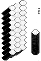
- the first solution for the sun-color filter comprises the usage of a multi-channel diffuser, which means an assembly of a plurality of parallel, individual diffusing elements, each one individually fulfilling the condition of the present invention, which are joined together, for example, in a honeycomb-like configuration, as shown in Fig. 2 , and where each individual element is separated from the others by means of an obscurant surface, whose details are shown at the bottom of Fig.2 .
- the filter Since the characteristic of the present invention refer to each of the constituting elements of the multichannel sun-color filter, the filter has to be disassembled if the condition of the present invention has to be tested by means of the measurement technique proposed in present description. Notably, all the tinges of the natural sunlight which vary in the different hours of the day can be obtained simply by adding in series a plurality of multi-channel sun-color filters here disclosed.
- each elementary disk must be a diffuser according to the present invention, and precisely a diffuser operated as a noon skylike diffuser, which means showing T (450 nm ) ⁇ T Max in the propagation direction.
- the absorbing elements comprise a plurality of thin parallel empty channels, which perfectly transmit light in the propagation direction but which absorb all components propagating off axis.
- the device operates using an alternate sequence of thin diffusing disks and obscurant grids in between.
- T ( ⁇ ) exp[- Nc scat ( ⁇ )], where c scat ( ⁇ ) is the single particle scattering cross section.
- the single-particle scattering cross section depends only on wavelength, index mismatch, and effective diameter, c scat ( ⁇ , m , D ).
- T ( ⁇ ) exp[- Nc scat ( ⁇ )], which gives the spectral profile of the transmitted light for the case of an impinging light with constant spectral intensity for all wavelengths, has been computed for a number of m , D pairs inside and outside the selected area.
- the resulting spectral distribution has been transformed in RGB amplitudes according to [ A.STOCKMAN AND L.T.SHARPE Vision Research vol. 40, 1711-1737 (2000 )] for providing eye-like visualization of the spectrum.
- Figure 5 shows the calculated, angularly resolved, scattering color maps, for four m , D pairs. The result are presented only for positive angles, 0° ⁇ ⁇ ⁇ 90°, i.e. for forward scattering, because in the Rayleigh limit forward and backward scattering are identical, while on moving away from this limit the scattering tends to become almost only in the forward direction.
- N ⁇ N Max and N ⁇ N min fulfilling T ⁇ T min and T ⁇ T Max , respectively are discussed in the following.
- the final effect here considered is that related to the presence of high volume-filling-fraction, f .
- f volume-filling-fraction
- the nanodiffuser according to the invention is a solid optical element which comprises a transparent solid matrix embedding a dispersion of transparent nanoparticles, whose average size d is in the range 10nm ⁇ d ⁇ 240nm.
- the optical element can have any shape, and volume. As list of possible examples, it is mentioned that it can be shaped as a parallelepiped, with any ratio among the length of different axis, thus including the case of panels and films, but it can be shaped as well having curved surfaces, i.e. as a cylinder, which can be completely filled or empty inside. It can be shaped as a tube, which can be straight or bent, or as a fiber. It can be also shaped as a lens.
- the dispersion of nanoparticles in the embedding matrix can be homogenous, or it can present, for example, gradients in filling fractions.
- the limits on the highest filling fraction discussed in the Optical section above are intended to be referred to the highest filling fraction present in the diffuser.
- all other quantities defined in the Optical section of above are average quantities, which therefore refer to the nanodiffuser as a whole, and are correctly defined also in the presence of a relevant non homogeneity of the considered diffuser.
- the matrix can be either organic or inorganic.
- Organic matrices suited for the purpose of the present invention are those that include, but are not limited to, the following:
- Inorganic matrices suited for the purpose of the present invention are those that include, but are not limited to: soda-lime-silica glass, borosilicate glass, fused silica etc.
- Transparency is fundamental when choosing an appropriate matrix for the sky-sun diffuser of the present invention.
- the transparency of the matrix should be preferentially very high with respect to both the total amount of power lost in transmission and with respect to distortion in the transmitted spectral profile (the matrix should not preferentially absorb any wavelength, and it is preferred that the material appears colorless for the thicknesses used for the nano-diffuser under consideration).
- a relevant example is polymethylmethacrylate (PMMA), which shows an absorption in the visible field of ⁇ 0,05% for 3 mm of thickness, and polycarbonate (PC), for which an absorption of 2% for 1mm thickness has been measured (these data refer to products on the market and the light transmittance has been measured with the test method DIN5036).
- the actual request on matrix transparency can be more or less strict.
- materials having the highest transparency might show limitations in other characteristics, for example related to mechanical properties, fire retarding characteristic, etc.
- the absorption eventually occurring in the matrix, for a given propagation direction is small in comparison to the scattering produced on the same beam in the same propagation direction because of the presence of the nano-particle dispersion, where by small it is meant that the absorption of light by the matrix should be less than 50%, preferably less than 20%, more preferably less than 5% of the scattering produced by the nanoparticle dispersion.
- the effect of the absorption caused by the matrix does not affect the value of nanocomposite Transmittance as defined by the measurement technique proposed in the present description since the contribution due to absorption is present both in the sample and in the reference channel.
- the same reasoning applies to the contribution of the reflection of the light at the entrance and exit surfaces of the sample.
- the mechanical properties of the organic matrices of the nanodiffuser of the invention should preferentially fall within the following range: TEST METHODS RANGES UNITS Tensile Strength ASTM D638 ISO 527 1-4 35-80 MPa at 23°C Compressive Strength ASTM D695 ISO 604 100-130 Mpa Flexural modulus ASTM D790 ISO 178 1500-3500 MPa Flexural Stress at break ASTM D790 ISO 527 60-130 MPa Charpy impact (notched) ASTM D6110 ISO 179 1-15 KJ/m 2 Notched Izod impact ASTM D256 ISO 180/1 A 1-20 KJ/m 2 Rockwell hardness ASTM D785 ISO 2039-2 105-130 R Scale, MPa
- the nanoparticles must have a real refractive index n p sufficiently different from that of the matrix, in order to allow light scattering to take place. Moreover, the nanoparticles should not absorb visible light, at least in an amount which will appreciably reduce the power and/or change the spectrum ( i.e. the color) of the total light exiting the diffuser ( i . e . the transmitted + the scattered + the reflected), with respect to the impinging one.
- the nanoparticles can be either organic and inorganic, the choice depending on the type of matrix. In the case of an organic matrix the most suited nanoparticles are inorganic particles. Organic particles, suited for the application, have an index of refraction too similar to that of the organic matrix, thus leading to a small difference between the indexes of refraction of the two media and to a low scattering efficiency.
- Organic particles on the other hand can be used with an inorganic matrix and can be made from any of the above-mentioned polymers.
- the shape of the nanoparticle can be any, even if spherical particles are preferred. In fact optimization of the optical properties of the diffuser often requires a careful choice of the particle size. When particles with large aspect ratio are used, the dispersion will behave in many respects as polydispersed.
- the best-suited materials to make the diffuser of the present invention are the ones made from organic matrices, in particular PMMA and PC.
- PMMA and PC are both plastics that are very easily produced using different methods.
- PC can be transformed by extrusion, thermoforming and injection moulding, while for PMMA all common processes may be used including injection moulding, compression moulding and extrusion, although the highest quality PMMA sheets are produced by the so called cell casting process.
- processes There are also many other processes that can be used for the production of the sky-sun diffuser, the choice of the process depending mainly on the type of matrix which is being used. The following is a brief list of processes by means of which our sky-sun diffuser can be prepared:
- Sky-sun diffusers according to the present invention having an inorganic matrix can be produced, for example, by means of the sol-gel method.
- sol-gel method There are two different possible approaches:
- Cell Casting polymerization is used, for example, for the production of PMMA.
- Two different approaches are followed to produce the sky-sun diffuser, here described as method A and B.
- the steps needed in order to obtain a well monodisperse suspension of nanoparticles in MMA comprise:
- MMA produced by Sigma Aldrich which contains 0-100 ppm monomethyl ether hydroquinone as inhibitor (in order to give the product a longer shelf life) is used.
- the inhibitor is removed, since it can disturb the polymerisation process. In order to do so the monomer is distilled at reduced pressure before use.
- the distilled monomer then undergoes at least one cycle of freeze and thaw. If kept covered from light and at low temperature (i.e in a fridge) the distilled monomer can last up to one week.
- MMA monomethyl ether hydroquinone
- Inorganic particles need to be surface treated in order to increase the compatibility between the two phases (organic/inorganic) and to reduce the surface energy, which due to the high ratio between the surface area of the nanofillers and that of the matrix, plays an important role in the stability of the system.
- various surface modification techniques are discussed. Common organic capping agents are thiols with long alkyl chains, which cover the nanoparticle surface and are highly compatible with the monomers. Other possibilities of surface modifications are by chemical reaction of the functionalities present on the surface (i.e silanization with silane molecules), for oxides nanoparticles they are typically hydroxyls, with proper reactive molecules, or by covering the particle with surfactant molecules that can be physically adsorbed on the surface.
- a complementary approach to increase the compatibility between inorganic nanoparticles and organic polymers is to cover the nanoparticle surface with a polymer coating.
- This coating can be made by using difunctional acrylic momomers such as: 2-Hydroxyethyl Acrylate (HEA), 2-Hydroxypropyl Acrylate (HPA), Butanediol Monoacrylate (BDMA),Glycidyl Methacrylate (GMA), diglycidyl ether of bisphenol A (DGEBA), Dimethylaminoethyl Methacrylate, DMAEMA Hydroxyethyl acrylate (HEA), Dimethylaminoethyl Acrylate (DMAEA).
- amino, glycidyl or hydroxy groups can strongly interact with the surface of the inorganic nanoparticles and the polymerization of the acrylic groups can create a rigid network around the particle.
- Inorganic particles can be bought already having a modified surface.
- examples of such particles are: Degussa TEGO® SUN Z800 (ZnO), Degussa VP AdNano® Z805 (ZnO), Degussa AEROXIDE® TiO 2 T805.
- the nanoparticles are added to the distilled monomer in order to form a suspension with a concentration of nanoparticlies of 1% in weight or more.
- the suspension is subject both to sonication and subsequently to centrifugation.
- the highly concentrated suspension is first sonicated using a 20kHz sonicator for 15 min. Big clusters of particles are thus broken up and a whitish suspension is obtained. Since it is not possible to break up all aggregates by means of sonication, centrifugation is needed in order to remove from the suspension large particles and aggregates having average particle sizes that do not fall within the range of average sizes according to the present invention.
- the initiator is needed to activate the polymerization process.
- the reaction that takes place is called chain growth polymerisation.
- unsaturated monomer molecules add on to a growing polymer chain one at a time.
- the process can be divided in three main steps:
- the radical initiator used in the present invention is Benzoyl peroxide (BPO, C 14 H 10 O 4 ). This choice is convenient since at 54°C (this is the temperature at which our reaction takes place) BPO has a half life of 156h and a decomposition rate of 1,23*10 -6 , thus it is possible to conduct the polymerization reaction of the nanocomposite having a PMMA matrix at a temperature far away from the boiling temperature of MMA and in reasonable amounts of time (about 1 day).
- BPO Benzoyl peroxide
- the suspension is poured into a glass mould and the reaction is carried out in a reactor, preheated at a temperature of 54°C, under continuous flux of nitrogen.
- the nanodiffuser is subject to a process of curing that can last up to 3 days at a temperature of 94°C in order to remove any residual monomer present inside the nanocomposite and to decompose any remaining BPO.
- the surfaces of the nanodiffuser are treated with appropriate lapping tools and abrasive chemicals in order to remove any superficial impurities that could compromise the optical properties of the diffuser.
- This method enables to control much better the auto acceleration effect and the problem of shrinkage, thus giving a final product having a much higher quality.
- This procedure consists of two steps: a pre-polymerization step and a polymerization step.
- a pre-polymerization step For a detailed description of the industrial process refer to Martin Rivera-Toledo et al.” Dynamic Modeling and Experimental Validation of the MMA Cell-Cast Process for Plastic Sheet Production" Ind. Eng. Chem. Res. 2006, 45, 8539-8553 .
- experimental conditions are set as modest monomer conversion values (15-20%) are obtained, the so obtained product is a very viscous liquid called a syrup.
- the syrup is obtained adding a small quantity of initiator to the monomer and by heating the system to a temperature below 100°C and above 50°C which depends on the half-life of the initiator. The system is kept at this temperature until the desired degree of conversion is reached. After this step the nanoparticles are added to the system.
- a radical initiator is responsible for starting the polymerization.
- a quantity of about 0.2% of a second radical initiator is dissolved in approximately 10% (calculated on the weight of syrup that is available) of pure distilled monomer. This mixture is added to the syrup containing nanoparticles and the system is kept stirring for about 1hour in order to gain a perfect mixture of the two phases.
- the dispersion is poured into a mould and polymerization reaction takes place in a water bath at a temperature of approximately 60°C.
- a two step process has been considered.
- PMMA pellets and small quantities of nanoparticles are mixed together using a double screw extruder to produce new pellets containing the nanoparticles, the so-called masterbatch.
- the master batch is usually at a very high concentration of nanoparticles, much higher than the 0.01% that is required.
- suitable quantities of masterbatch are mixed with PMMA in order to produce pellets having the desired concentration. These nanocomposite pellets will then be shaped in the desired way through the moulding process.
- Another method that can be used for the production of diffusers according to the present invention makes use of both cell casting and extrusion techniques.
- a thick sample containing a large number of particles is prepared.
- large number it is meant that the sample operates in large multiple scattering regime, if used as it is.
- the particle concentration should not exceed the value above which, for the given particle size, the resulting particle position distribution looses its randomness (see section on the optical properties).
- the sample should not contain a significant number of particle aggregates, or clusters where the local concentration is larger than the limit imposed by the set maximum filling fraction, since this circumstance will deteriorate the final optical quality of the composite.
- This nanocomposite is then broken up into small pieces and is fed into the extruder together with a suitable quantity of PMMA pellets in order to lead to the development of a final diffuser whose total number of particles seen by the testing light beam has the desired value (for example, it is below the limit for multiple scattering, if this process has to be hindered in respect to the illuminating direction considered).
- This method leads to a final diffuser, which appears homogenous at the macroscopic (mm-m) scale, but which is inhomogeneous not only at the nm level, but also at the intermediate, ⁇ m-mm scale.
- the diffuser scattering properties are determined by the average particle distribution, being the total number of particle in the beam path what determines the scattering, no matter if these particles are evenly or unevenly distributed in the diffuser.
- the average particle distribution being the total number of particle in the beam path what determines the scattering, no matter if these particles are evenly or unevenly distributed in the diffuser.
- the use of beads of nanocomposite material can be implemented also for industrial cell-casting production of the nanodiffuser, where large volume nano-composite diffusers are developed.
- T ( ⁇ ) the "Monochromatic Normalized Collinear Transmittance, T ( ⁇ )" of the diffuser at the selected wavelength and propagation direction.
- the quantity is the ratio between the transmittance of the diffuser in the propagation direction, which does not account for the contribution of the scattered light, and the transmittance of a reference sample identical to the diffuser except for the fact that it does not contain the transparent nanoparticles.
- the proposed measurement procedure provides the ratio between: (i) the Monochromatic Collinear Transmittance of the diffuser add: (ii) Monochromatic Collinear Transmittance of a reference sample identical to the diffuser except for the fact that it does not contain the transparent nanoparticles, said ratio being the quantity here defined as: "Monochromatic Normalized Collinear Transmittance of the diffuser
- the experimental apparatus illustrated in Figure 9 and Figure 10 , comprises:
- the beam is then split in two equal arms, which are sent to the samples. In the following it is called channel 1 (top in the figure) the one used for the reference, and channel 2 (bottom) the one used for the nanodiffuser.
- the transmitted components are focused by achromatic lenses (12, 17) on two pin holes (13, 18), whose size is set to select only the radiation transmitted by the samples within a 5mrad divergence angle.
- the choice of such small solid angle ensures that the light scattered by the sample at any angle does not contribute to the signal which is detected after the pin hole.
- Neutral density filters (11, 16) are used to optimally match the detector dynamic range. If it happens that the sample has a high reflectivity coating on one face, so that the light is not transmitted through the sample, the technique to be used is shown in Fig. 10 .
- the apparatus is identical to the previous one, with the only difference that the beam is transmitted, reflected and then transmitted again through the sample before being sent to the spatial filter and detection.
- the main problem in ascertaining the contribution to attenuation caused by the scattering is that of isolating it from the other two contributions caused by the reflection at the entrance and exit air-diffuser interfaces, and by the possible absorption caused by the matrix or other spurious components in the sample.
- This problem is solved by the method here proposed because the diffuser is tested against a reference sample which is virtually identical to the diffuser with the only exception that it does not contain the nanoparticles
- the procedure is repeated identical, changing only the light source.
- Each measurement procedure is performed in two steps.
- This step is aimed at removing any possible contribution due to the asymmetry existing between the two channels.
- two identical reference samples are positioned in place 10 and 15, where suitable holders exist to ensure maximum reproducibility in sample positioning. If P 0 is the power of the used laser, T A is transmittance that the reference sample would have in the presence of the sole absorption effect and T R transmittance that the reference sample would have in the presence of the sole reflection, the two detectors will now measure the two signals:
- the reference sample in channel 2 is replaced by the nano-diffuser which should be characterized.
- P ' 0 which might be the same or different from P 0
- the procedure implies to take the minimum measured Transmittance if the goal is to determine T min' and the maximum measured Transmittance if the goal is to determine T Max .
- a sky-sun diffuser was produced by means of an in situ bulk polymerization technique.
- Methylmethacrilate was used for the matrix and Degussa AEROXIDE TiO 2 T805 for the nanoparticles, which have a nominal dimension of 21 nm (as given by the producer).
- the particles, as received from the producer, are in the form of macro agglomerates with dimensions up to 1 ⁇ m. In order to use them the agglomerates were separated into the primary particles.
- a first step to reach this goal consisted in the sonication of a high concentrated (about 1% in weight) suspension of TiO 2 nanoparticles in MMA. The duration of this process depends on the power of the employed instrument and on the volume of the dispersion.
- the suspension of TiO 2 nanoparticles in MMA was sonicated for 15 minutes. This process alone was not enough to separate all the agglomerates and to obtain a distribution of particles having a mean size of less than 80nm.
- a further step needed to be taken. In this second step only those particles having the desired dimension ( ⁇ 80nm) were selected and those having bigger sizes were discarded. This was carried out by using a centrifuge that reaches an acceleration of about 3421g for 14 minutes in order to obtain a suspension containing only TiO 2 nanoparticles with sizes of 69,5nm.
- the average particle size was measured using Dynamic Light Scattering (DLS) Technique.
- DLS Dynamic Light Scattering
- the suspension containing the nanoparticles having the selected sizes was diluted in order to obtain 30ml of suspension with a concentration ranging from 100 to 400ppm in weight of TiO 2 nanoparticles.
- the suspension was subjected to three cycles of freeze and thaw. Since thermal cycles cause the aggregation of particles, it was necessary to sonicate the suspension once more (5 min) before the next step.
- the reaction lasted 36 hours at the temperature of 54°C.
- the bulk diffusers were subjected to a curing process at a temperature of 94°C for 3 days in order to increase the degree of polymerization and to decompose any residual BPO.
- the bulk diffuser was then treated in order to remove impurities from the surface, which could degrade the optical quality of the diffuser.
- the sky-sun nanodiffusers produced using this method had a thickness of 1cm.
- ⁇ and T(450nm) were shown. Concentration was varied in order to show the impact of an increase in the number of particles on the transmission properties of the sky-sun diffuser.
- the scattering behaves very close to the Rayleigh limit for all concentrations, thus confirming that no particle aggregations occurred PARTICLE EFFECTIVE SIZE, D [nm] m CONCENTRATION (PPM) ⁇ T 450 98 1,9 30 3,87 0,82 98 1.9 100 3,87 0,52 98 1,9 300 3,86 0,14
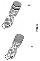
- Fig. 11 (top) outlines the effect of Rayleigh back scattering when three sky-sun nanodiffuser disks were front illuminated by a commercial InGaN white LED, and seen against a dark background. The result shows that the color of the back-scattered light is Azure, similar to that of the noon sky.
- Fig 11 (bottom) shows a collage (increasing exposure time from right to left) of snapshots obtained when the same disks were illuminated by the same LED from right side, so that light was guided inside the disks due to total internal reflection at the disk surface. Rayleigh scattering now diffuses out of the disks first the Azure, than the Yellow, and finally the Orange and the Red colors.
Landscapes
- Physics & Mathematics (AREA)
- Spectroscopy & Molecular Physics (AREA)
- General Physics & Mathematics (AREA)
- Optics & Photonics (AREA)
- Engineering & Computer Science (AREA)
- General Engineering & Computer Science (AREA)
- Chemical & Material Sciences (AREA)
- Dispersion Chemistry (AREA)
- Non-Portable Lighting Devices Or Systems Thereof (AREA)
- Optical Elements Other Than Lenses (AREA)
- Addition Polymer Or Copolymer, Post-Treatments, Or Chemical Modifications (AREA)
- Optical Filters (AREA)
- Planar Illumination Modules (AREA)
Claims (19)
- Diffuseur optique solide de type ciel-soleil capable de reproduire - lorsqu'il est éclairé par une lumière blanche visible - la présence simultanée de deux composantes chromatiques différentes: une lumière du ciel diffusée, dans laquelle le bleu est dominant, et une lumière du soleil transmise, avec une composante bleue limitée ; ledit diffuseur optique comprenant une matrice solide transparente contenant une dispersion de nanoparticules transparentes ayant une taille moyenne d dans la gamme 10 nm ≤ d ≤ 240 nm ;
dans lequel:- le rapport entre les densités optiques de diffusion bleue et rouge γ Log[T(450 nm)]/Log[T(630 nm)] dudit diffuseur optique se situe dans la gamme 5 ≥ γ 2,5, où T(λ) est un facteur de transmission colinéaire monochromatique normalisé du diffuseur optique, défini comme le rapport entre le facteur de transmission du diffuseur optique dans la direction de propagation, sans la contribution de la lumière diffusée, et le facteur de transmission d'un échantillon de référence identique au diffuseur optique excepté qu'il ne contient pas les nanoparticules transparentes; le facteur de transmission colinéaire monochromatique normalisé du diffuseur à une longueur d'onde de mesure et le long d'une direction de mesure étant mesure:a) en faisant traverser le diffuseur par un faisceau de lumière quasi-monochromatique non polarisée ayant une longueur d'onde centrale égale à la longueur d'onde de mesure, une largeur de bande spectrale inférieure à 10 nm et une divergence angulaire inférieure à 5 mrad ;b) en mesurant une première puissance rayonnée du faisceau de lumière incident sur le diffuseur ;c) en mesurant une deuxième puissance rayonnée du faisceau de lumière se propageant au-delà du diffuseur, le long de la direction de mesure et à l'intérieur de ladite divergence angulaire;d) en déterminant un premier rapport entre ladite deuxième et ladite première puissance rayonnée ;e) en répétant les étapes a) à d) sur l'échantillon de référence, de manière à déterminer un deuxième rapport, relatif à l'échantillon de référence ; etf) en déterminant un troisième rapport entre le premier et le deuxième rapport, le facteur de transmission colinéaire monochromatique normalisé étant égal au troisième rapport ;- le long d'au moins une première direction de propagation, le facteur de transmission colinéaire monochromatique normalisé du diffuseur optique est T(450 nm) ≥ 0,4 ;- le long d'au moins une deuxième direction de propagation, le facteur de transmission colinéaire monochromatique normalisé du diffuseur optique est T(450 nm) ≤ 0,9, ladite deuxième direction de propagation étant identique à, ou différente de, la première direction de propagation. - Diffuseur selon la revendication 1, dans lequel le long de ladite deuxième direction, le facteur de transmission colinéaire monochromatique normalisé du diffuseur optique est T(450 nm) ≤ 0,8.
- Diffuseur selon la revendication 1, dans lequel le long de ladite deuxième direction, le facteur de transmission colinéaire monochromatique normalisé du diffuseur optique est T(450 nm) ≤ 0,7.
- Diffuseur selon l'une quelconque des revendications 1 à 3, dans lequel ladite deuxième direction est identique à la première direction.
- Diffuseur selon l'une quelconque des revendications 1 à 3, dans lequel ladite deuxième direction est orthogonale à ladite première direction, et dans lequel le long de ladite deuxième direction le facteur de transmission colinéaire monochromatique du diffuseur optique est T(λ) ≤ 0,5 pour λ ≤ 570 nm.
- Diffuseur selon la revendication 5, dans lequel le long de ladite deuxième direction, le facteur de transmission colinéaire monochromatique du diffuseur optique est T(λ) ≤ 0, 3 pour λ ≤ 570 nm.
- Diffuseur selon la revendication 5, dans lequel le long de ladite deuxième direction, le facteur de transmission colinéaire monochromatique du diffuseur optique est T(λ) ≤ 0,1 pour λ ≤ 570 nm.
- Diffuseur selon l'une quelconque des revendications 1 à 7, dans lequel l'indice de réfraction relatif

- Diffuseur selon la revendication 8, dans lequel, le long d'au moins la première direction, le nombre de nanoparticules par unité de surface est N ≤ Nmax =
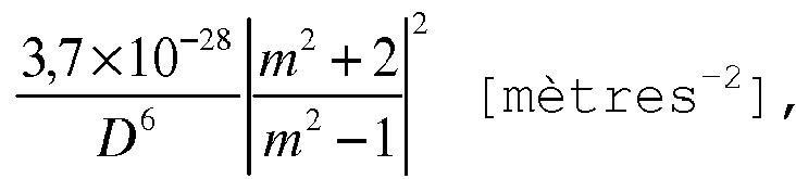
- Diffuseur selon la revendication 8, dans lequel, le long d'au moins la deuxième direction, le nombre de nanoparticules par surface unitaire est N ≥ Nmin =

- Diffuseur selon l'une quelconque des revendications 1 à 7, caractérisé en ce que:i. si
 ii. si D = dnh, on vérifie que
D[nm] ≤ 132m + 115 pour 0,7 ≤ m ≤ 0,95
D[nm] ≤ 240 pour 1,05 ≤ m < 1,35, et
D[nm] ≤ -135m + 507 pour 1,35 ≤ m ≤ 2,1 ;iii. si N [mètres-2] est le nombre de particules par unité de surface et D est donné en mètres, le long d'au moins la première direction, on vérifie que N ≤ Nmax = iv. si N [mètres-2] est le nombre de particules par unité de surface et D est donné en mètres, le long d'au moins la deuxième direction, on vérifie que N ≥ Nmin =
- Diffuseur selon l'une quelconque des revendications 1 à 7, dans lequel la fraction de remplissage maximale est f ≤ 10-2.
- Diffuseur selon la revendication 11, dans lequel la fraction de remplissage maximale est f ≤ 10-3.
- Diffuseur selon l'une quelconque des revendications 5 à 7, étant en outre conformé comme un panneau parallélépipédique où le rapport entre la plus grande dimension L et la plus petite dimension W est L/W ≥ 20.
- Diffuseur selon l'une quelconque des revendications 5 à 7, étant en outre conformé comme un cylindre ayant une longueur supérieure à dix fois le diamètre.
- Diffuseur selon l'une quelconque des revendications 1 à 7, étant en outre conformé comme un élément optique réfractif.
- Système optique comprenant un diffuseur selon la revendication 1 ou 14 et une source de lumière couplée à un côté du diffuseur de telle sorte que la lumière générée par la source est partiellement guidée à l'intérieur du diffuseur par réflexion totale interne et partiellement diffusée hors du diffuseur en raison de l'action des nanoparticules dispersées.
- Système optique comprenant un diffuseur selon l'une quelconque des revendications 1 à 16 et une surface miroir, le diffuseur étant appliqué à la surface miroir.
- Système optique comprenant un diffuseur selon l'une quelconque des revendications 1 à 16 et un revêtement à haute réflectivité, ledit diffuseur ayant deux plus grandes faces, ledit revêtement étant déposé sur l'une des deux plus grandes faces.
Priority Applications (1)
| Application Number | Priority Date | Filing Date | Title |
|---|---|---|---|
| EP16162706.2A EP3078905A1 (fr) | 2008-06-24 | 2009-06-19 | Diffuseur de soleil optique |
Applications Claiming Priority (2)
| Application Number | Priority Date | Filing Date | Title |
|---|---|---|---|
| IT001135A ITMI20081135A1 (it) | 2008-06-24 | 2008-06-24 | Dispositivo di illuminazione |
| PCT/EP2009/057674 WO2009156348A1 (fr) | 2008-06-24 | 2009-06-19 | Diffuseur de soleil optique |
Related Child Applications (1)
| Application Number | Title | Priority Date | Filing Date |
|---|---|---|---|
| EP16162706.2A Division EP3078905A1 (fr) | 2008-06-24 | 2009-06-19 | Diffuseur de soleil optique |
Publications (2)
| Publication Number | Publication Date |
|---|---|
| EP2304478A1 EP2304478A1 (fr) | 2011-04-06 |
| EP2304478B1 true EP2304478B1 (fr) | 2016-03-30 |
Family
ID=40301842
Family Applications (5)
| Application Number | Title | Priority Date | Filing Date |
|---|---|---|---|
| EP09769197.6A Active EP2304478B1 (fr) | 2008-06-24 | 2009-06-19 | Diffuseur de soleil optique |
| EP15164751.8A Active EP2918903B1 (fr) | 2008-06-24 | 2009-06-19 | Dispositif d'éclairage |
| EP09769196.8A Active EP2304480B1 (fr) | 2008-06-24 | 2009-06-19 | Dispositif d éclairage |
| EP16206852.2A Revoked EP3181999B1 (fr) | 2008-06-24 | 2009-06-19 | Dispositif d'éclairage |
| EP16162706.2A Withdrawn EP3078905A1 (fr) | 2008-06-24 | 2009-06-19 | Diffuseur de soleil optique |
Family Applications After (4)
| Application Number | Title | Priority Date | Filing Date |
|---|---|---|---|
| EP15164751.8A Active EP2918903B1 (fr) | 2008-06-24 | 2009-06-19 | Dispositif d'éclairage |
| EP09769196.8A Active EP2304480B1 (fr) | 2008-06-24 | 2009-06-19 | Dispositif d éclairage |
| EP16206852.2A Revoked EP3181999B1 (fr) | 2008-06-24 | 2009-06-19 | Dispositif d'éclairage |
| EP16162706.2A Withdrawn EP3078905A1 (fr) | 2008-06-24 | 2009-06-19 | Diffuseur de soleil optique |
Country Status (8)
| Country | Link |
|---|---|
| US (8) | US8622560B2 (fr) |
| EP (5) | EP2304478B1 (fr) |
| DK (2) | DK2304480T3 (fr) |
| ES (2) | ES2582103T3 (fr) |
| HU (1) | HUE029104T2 (fr) |
| IT (1) | ITMI20081135A1 (fr) |
| PL (2) | PL2304478T3 (fr) |
| WO (2) | WO2009156348A1 (fr) |
Families Citing this family (97)
| Publication number | Priority date | Publication date | Assignee | Title |
|---|---|---|---|---|
| US20140362563A1 (en) * | 2013-06-05 | 2014-12-11 | Scott M. Zimmerman | Fixtures for large area directional and isotropic solid state lighting panels |
| ITMI20081135A1 (it) | 2008-06-24 | 2009-12-25 | Trapani Paolo Di | Dispositivo di illuminazione |
| CN102734742B (zh) | 2011-04-13 | 2016-08-03 | 皇家飞利浦电子股份有限公司 | 用于获得日光外观的光学元件、光照系统和灯具 |
| EP2546319A1 (fr) * | 2011-07-13 | 2013-01-16 | Koninklijke Philips Electronics N.V. | Composants de conversion lumineuse plastique haute efficacité par l'incorporation de phosphore dans un polymère par l'ajout de monomères avant la polymérisation |
| ES2556581T3 (es) * | 2011-07-20 | 2016-01-19 | Koninklijke Philips N.V. | Un sistema de iluminación para proporcionar una apariencia de luz diurna y una luminaria |
| JP6087918B2 (ja) * | 2011-07-20 | 2017-03-01 | フィリップス ライティング ホールディング ビー ヴィ | 天窓の体裁を提供する照明エレメント、照明システム、および、ルミナリエ |
| US9147282B1 (en) | 2011-11-02 | 2015-09-29 | Bentley Systems, Incorporated | Two-dimensionally controlled intuitive tool for point cloud exploration and modeling |
| US8963921B1 (en) * | 2011-11-02 | 2015-02-24 | Bentley Systems, Incorporated | Technique for enhanced perception of 3-D structure in point clouds |
| JP2013125693A (ja) * | 2011-12-15 | 2013-06-24 | Koito Mfg Co Ltd | 車両用灯具 |
| EP2880474A4 (fr) * | 2012-08-01 | 2016-03-23 | Ferro Corp | Nanocouche influençant la lumière |
| DE102012016771A1 (de) * | 2012-08-24 | 2014-02-27 | GM Global Technology Operations LLC (n. d. Ges. d. Staates Delaware) | Instrument mit Ziffernblatt für ein Kraftfahrzeug und Verfahren zur Herstellung desselben |
| JP6173456B2 (ja) * | 2012-08-24 | 2017-08-02 | フィリップス ライティング ホールディング ビー ヴィ | 照明デバイス |
| JP2015534701A (ja) | 2012-08-28 | 2015-12-03 | デロス リビング エルエルシーDelos Living Llc | 居住環境に関連するウェルネスを増進するためのシステム、方法、及び物品 |
| US9711748B2 (en) | 2012-08-29 | 2017-07-18 | Boe Technology Group Co., Ltd. | OLED devices with internal outcoupling |
| KR101675963B1 (ko) * | 2012-09-06 | 2016-11-15 | 한국전자통신연구원 | 무선통신 시스템에서의 변조방식 분류 장치 및 방법 |
| US9293948B2 (en) * | 2012-09-19 | 2016-03-22 | Sundial Energy, Inc. | Renewable uninterrupted power supply for critical node infrastructure support |
| US10162471B1 (en) | 2012-09-28 | 2018-12-25 | Bentley Systems, Incorporated | Technique to dynamically enhance the visualization of 3-D point clouds |
| EP2920505B1 (fr) | 2012-11-14 | 2020-05-13 | CoeLux S.r.l. | Dispositif d'éclairage synthétisant la lumière provenant d'un objet à une distance virtuellement infinie |
| DK2920511T3 (da) | 2012-11-14 | 2020-07-27 | Coelux Srl | Kunstig belysningsindretning til at generere naturligt lys |
| ITTO20120988A1 (it) * | 2012-11-14 | 2014-05-15 | Light In Light S R L | Sistema di illuminazione artificiale per simulare un'illuminazione naturale |
| US9732941B2 (en) | 2013-03-11 | 2017-08-15 | Lighthouse Tech Pte. Ltd. | Diffuse light source and visual dazzler system made therefrom |
| JP6511059B2 (ja) * | 2013-09-16 | 2019-05-08 | コエルクス・エッセ・エッレ・エッレCoeLux S.r.l. | ポリマーマトリクスとナノ粒子を含む複合材料、その製造方法及び使用 |
| EP3111137B1 (fr) | 2014-02-28 | 2019-08-28 | Signify Holding B.V. | Système d'éclairage |
| EP3754588B1 (fr) | 2014-02-28 | 2023-08-16 | Delos Living LLC | Systèmes, procédés et articles pour améliorer le bien-être associé à des environnements habitables |
| BR112016020450A2 (pt) * | 2014-03-10 | 2017-10-24 | Coelux Srl | sistema de iluminação |
| EP2918901B1 (fr) | 2014-03-10 | 2018-07-18 | CoeLux S.r.l. | Système d'éclairage |
| CN109296996B (zh) * | 2014-05-13 | 2021-01-05 | 科勒克斯有限责任公司 | 色镜、色板及其应用 |
| ES2671553T3 (es) | 2014-05-13 | 2018-06-07 | Coelux S.R.L. | Fuente de luz y sistema de iluminación que imita la luz solar |
| WO2015173770A2 (fr) | 2014-05-14 | 2015-11-19 | Coelux S.R.L. | Dispositif d'éclairage simulant l'éclairage naturel et comprenant une source de lumière infrarouge |
| US10072820B2 (en) * | 2014-05-26 | 2018-09-11 | Philips Lighting Holding B.V. | Tunable daylight experience using micro faceted foils |
| US9797141B2 (en) | 2014-06-04 | 2017-10-24 | Abl Ip Holding Llc | Light fixture with photosensor-activated adjustable louver assembly |
| US9897289B2 (en) | 2014-06-04 | 2018-02-20 | Abl Ip Holdings Llc | Light fixture with photosensor-activated adjustable louver assembly and color temperature control |
| CN104110614A (zh) * | 2014-07-08 | 2014-10-22 | 北京京东方视讯科技有限公司 | 一种白光led光源、背光模组及显示装置 |
| WO2016067609A1 (fr) * | 2014-10-28 | 2016-05-06 | 株式会社 東芝 | Source de lumière blanche et système de source de lumière blanche |
| WO2016085364A1 (fr) * | 2014-11-28 | 2016-06-02 | Алексей Николаевич МИРОНОВ | Source lumineuse linéaire à base de diodes électroluminescentes (et variantes) |
| EP3243026A4 (fr) * | 2015-01-06 | 2018-08-29 | GE Lighting Solutions, LLC | Matériaux et guides lumineux pour filtrage de couleur dans des unités d'éclairage |
| WO2016134732A1 (fr) | 2015-02-23 | 2016-09-01 | Coelux S.R.L. | Système d'éclairage de siège |
| EP3262338B1 (fr) | 2015-02-23 | 2019-01-02 | CoeLux S.r.l. | Système d'éclairage pour perception optiquement élargie |
| KR20170129821A (ko) | 2015-03-18 | 2017-11-27 | 코에룩스 에스알엘 | 매트릭스 및 산란 요소를 포함하는 복합 시스템, 그 제조방법 및 그 용도 |
| EP3130842B1 (fr) | 2015-07-15 | 2019-09-25 | CoeLux S.r.l. | Système d'éclairage de voûte |
| EP3322931B1 (fr) * | 2015-07-15 | 2020-04-22 | CoeLux S.r.l. | Unité réfléchissante chromatique |
| EP3323006A1 (fr) | 2015-07-15 | 2018-05-23 | CoeLux S.r.l. | Système d'éclairage réfléchissant permettant une perception optiquement élargie |
| KR102255641B1 (ko) * | 2015-08-28 | 2021-05-26 | 코에룩스 에스알엘 | 대면적 광원 및 대면적 조명기구 |
| US10508793B2 (en) | 2015-09-16 | 2019-12-17 | Innerscene, Inc. | Artificial skylight and methods |
| DE102015116718A1 (de) * | 2015-10-01 | 2017-04-06 | Osram Opto Semiconductors Gmbh | Optoelektronisches Bauelement mit einem Diffusorelement |
| DE102015116710A1 (de) * | 2015-10-01 | 2017-04-06 | Osram Opto Semiconductors Gmbh | Optoelektronisches Bauelement |
| ITUB20155577A1 (it) * | 2015-11-13 | 2017-05-13 | Coelux Srl | Sistema di illuminazione che simula l'illuminazione naturale e include una sorgente di luce infrarossa |
| CN109153232B (zh) * | 2015-11-19 | 2021-06-08 | 科勒克斯有限责任公司 | 用于太阳天空模拟照明系统的分层面板结构 |
| EP3377813B1 (fr) | 2015-11-19 | 2019-08-28 | CoeLux S.r.l. | Système d'éclairage modulaire imitant le soleil-ciel |
| US9894729B2 (en) | 2015-12-15 | 2018-02-13 | Arborlight, Inc. | Artificial light configured for daylight emulation |
| US10120119B2 (en) * | 2015-12-24 | 2018-11-06 | Minebea Mitsumi Inc. | Planar illumination apparatus with scattering unit by rayleigh scattering |
| EP3405721B1 (fr) | 2016-01-19 | 2019-11-20 | Signify Holding B.V. | Dispositif d'éclairage |
| US10670228B2 (en) | 2016-03-07 | 2020-06-02 | Coelux S.R.L. | Sun-sky imitating lighting system with enlarged perceived window area |
| CN105891936B (zh) * | 2016-05-20 | 2019-11-01 | 京东方科技集团股份有限公司 | 导光元件及其制作方法以及背光模组 |
| WO2018091060A1 (fr) | 2016-11-19 | 2018-05-24 | Coelux S.R.L. | Système d'éclairage comprenant un système optique affectant l'apparence |
| CN110088649B (zh) * | 2016-11-19 | 2022-08-09 | 科勒克斯有限责任公司 | 阳光模拟照明系统中的调整装置 |
| MX383389B (es) * | 2016-11-24 | 2025-03-13 | Optical Saver Tech S A P I De C V | Dispositivo optico para incrementar la emision de luz util en fuentes electro-luminiscentes, mediante la retroreflexion selectiva de las longitudes de onda de alta energia de dicha luz emitida. |
| EP3336412B1 (fr) | 2016-12-13 | 2020-04-08 | CoeLux S.r.l. | Système de simulation de l'apparance de la lune |
| US10830405B2 (en) | 2017-02-28 | 2020-11-10 | Coelux S.R.L. | Sunlight-based large area light source and large area luminaire |
| CN110382948B (zh) | 2017-02-28 | 2021-09-21 | 科勒克斯有限责任公司 | 基于阳光的太阳模拟照明 |
| US10648640B2 (en) * | 2017-03-21 | 2020-05-12 | Valeo North America, Inc. | Light emitting diode (LED) pad mount system |
| JP6837220B2 (ja) * | 2017-03-29 | 2021-03-03 | パナソニックIpマネジメント株式会社 | 照明装置 |
| JP6401330B2 (ja) * | 2017-04-12 | 2018-10-10 | コエルクス・エッセ・エッレ・エッレCoeLux S.r.l. | 人工照明装置 |
| WO2019046580A1 (fr) | 2017-08-30 | 2019-03-07 | Delos Living Llc | Systèmes, procédés et articles pour évaluer et/ou améliorer la santé et le bien-être |
| JPWO2019043872A1 (ja) * | 2017-08-31 | 2020-10-01 | 興和株式会社 | 照明装置 |
| WO2019064257A1 (fr) | 2017-09-28 | 2019-04-04 | Coelux S.R.L. | Dispositif optique destiné à un système amélioré d'éclairage pour simuler un éclairage naturel dans deux demi-espaces |
| JP6756067B2 (ja) | 2018-05-18 | 2020-09-16 | 三菱電機株式会社 | 照明ユニットおよび照明器具 |
| IT201800005634A1 (it) | 2018-05-23 | 2019-11-23 | Struttura a film multistrato cromaticamente diffondente per sistemi di illuminazione simulanti cielo-sole | |
| IT201800005680A1 (it) | 2018-05-24 | 2019-11-24 | Illuminazione a luce bianca regolabile | |
| JP7066304B2 (ja) * | 2018-08-07 | 2022-05-13 | 三菱電機株式会社 | 照明装置及び照明ユニット |
| JP6592154B2 (ja) * | 2018-09-05 | 2019-10-16 | コエルクス・エッセ・エッレ・エッレCoeLux S.r.l. | 人工照明装置 |
| JP2019023736A (ja) * | 2018-09-05 | 2019-02-14 | コエルクス・エッセ・エッレ・エッレCoeLux S.r.l. | 有色パネル、照明システム、及び部屋 |
| EP3850458A4 (fr) | 2018-09-14 | 2022-06-08 | Delos Living, LLC | Systèmes et procédés d'assainissement d'air |
| DE102018123789A1 (de) | 2018-09-26 | 2020-03-26 | Carl Zeiss Jena Gmbh | Leuchteinrichtung für ein Fahrzeug |
| WO2020176503A1 (fr) | 2019-02-26 | 2020-09-03 | Delos Living Llc | Procédé et appareil d'éclairage dans un environnement de bureau |
| EP3933257A4 (fr) * | 2019-02-27 | 2022-04-06 | Mitsubishi Electric Corporation | Dispositif d'éclairage, fenêtre à fonction d'éclairage et matériau de construction de fenêtre |
| US10874006B1 (en) | 2019-03-08 | 2020-12-22 | Abl Ip Holding Llc | Lighting fixture controller for controlling color temperature and intensity |
| US11898898B2 (en) | 2019-03-25 | 2024-02-13 | Delos Living Llc | Systems and methods for acoustic monitoring |
| WO2020196594A1 (fr) | 2019-03-28 | 2020-10-01 | 三菱電機株式会社 | Diffuseur, unité d'éclairage, et dispositif d'éclairage |
| IT201900004783A1 (it) | 2019-03-29 | 2020-09-29 | Coelux Srl | Generatore di luce diretta per sistemi di illuminazione a imitazione cielo - sole |
| IT201900004775A1 (it) | 2019-03-29 | 2020-09-29 | Coelux Srl | Sistema di illuminazione a imitazione cielo - sole |
| CN110778927A (zh) * | 2019-10-29 | 2020-02-11 | 中国计量大学 | 一种产生天蓝色天空光的人工照明装置 |
| JP7051023B2 (ja) * | 2019-11-19 | 2022-04-08 | 三菱電機株式会社 | 光拡散体、照明器具および光拡散体の製造方法 |
| WO2021224161A1 (fr) * | 2020-05-05 | 2021-11-11 | Signify Holding B.V. | Émulation d'éclairage extérieur immersif |
| CN111649271B (zh) * | 2020-07-08 | 2023-06-20 | 喜洋阳(南京)科技发展有限公司 | 一种瑞利散射阳光灯 |
| WO2022007095A1 (fr) * | 2020-07-08 | 2022-01-13 | 千奥星科南京生物科技有限公司 | Lampe à lumière solaire à diffusion de rayleigh |
| KR102197383B1 (ko) * | 2020-07-27 | 2020-12-31 | 써니파이브 주식회사 | 자연광과 유사한 광을 제공하는 조명 장치 |
| EP4189286B1 (fr) | 2020-07-29 | 2024-07-03 | CoeLux S.r.l. | Dispositif d'éclairage pour simuler la lumière naturelle |
| IT202100000077A1 (it) | 2021-01-04 | 2022-07-04 | Coelux Srl | Filtro ottico, dispositivo di illuminazione che simula la luce naturale del cielo e del sole impiegante lo stesso e processo di produzione di un filtro ottico |
| IT202100000074A1 (it) | 2021-01-04 | 2022-07-04 | Coelux Srl | Filtro ottico, dispositivo di illuminazione che simula la luce naturale del cielo e del sole impiegante lo stesso e processo di produzione di un filtro ottico |
| GB2607859B (en) * | 2021-04-13 | 2023-09-20 | Innerscene Ltd | Optical display device |
| WO2022249433A1 (fr) | 2021-05-28 | 2022-12-01 | 三菱電機株式会社 | Corps de diffusion et dispositif d'éclairage |
| US20230197749A1 (en) * | 2021-12-22 | 2023-06-22 | Visera Technologies Company Ltd. | Light diffuser, image sensor package having the same, and manufacturing method thereof |
| GB2619978A (en) | 2022-06-24 | 2023-12-27 | Innerscene Ltd | Optical display device |
| CN119546899A (zh) * | 2022-07-12 | 2025-02-28 | 昕诺飞控股有限公司 | 用于人造天窗和窗户的云 |
| IT202300011538A1 (it) | 2023-06-06 | 2024-12-06 | Coelux Srl | Dispositivo di illuminazione a risparmio energetico per simulare l’illuminazione naturale |
| CN120781576B (zh) * | 2025-09-09 | 2025-12-05 | 自然资源部第二海洋研究所 | 一种水色遥感通用瑞利散射确定方法及系统 |
Family Cites Families (37)
| Publication number | Priority date | Publication date | Assignee | Title |
|---|---|---|---|---|
| US2831966A (en) * | 1954-04-19 | 1958-04-22 | Analite Corp | Lighting fixtures |
| US3302016A (en) | 1964-08-21 | 1967-01-31 | Textron Electronics Inc | Optical collimating system |
| US3907581A (en) | 1972-03-23 | 1975-09-23 | Du Pont | Opalescent TiO{HD 2{B -containing compositions |
| IL50125A (en) * | 1976-07-26 | 1980-11-30 | Yeda Res & Dev | Holographic focusing screens |
| DE3916997C2 (de) * | 1988-06-16 | 1994-04-14 | Tetsuhiro Kano | Beleuchtungsvorrichtung |
| US5083252A (en) | 1990-04-19 | 1992-01-21 | Tailored Lighting Company, Inc. | Apparatus for producing light distributions |
| US5251392A (en) * | 1991-02-08 | 1993-10-12 | Vemco Corporation | Artificial window |
| GB9314604D0 (en) * | 1993-07-14 | 1993-08-25 | Dow Deutschland Inc | Light diffuser composition |
| US6429583B1 (en) | 1998-11-30 | 2002-08-06 | General Electric Company | Light emitting device with ba2mgsi2o7:eu2+, ba2sio4:eu2+, or (srxcay ba1-x-y)(a1zga1-z)2sr:eu2+phosphors |
| JP2001053341A (ja) * | 1999-08-09 | 2001-02-23 | Kazuo Kobayashi | 面発光表示器 |
| US6577073B2 (en) * | 2000-05-31 | 2003-06-10 | Matsushita Electric Industrial Co., Ltd. | Led lamp |
| WO2002000891A2 (fr) | 2000-06-26 | 2002-01-03 | Bayer Aktiengesellschaft | Regulation de la protease aspartyle humaine de type napsin |
| WO2002008799A2 (fr) * | 2000-07-14 | 2002-01-31 | Ledalite Architectural Products Inc. | Dispositifs de commande de lumiere et procedes mis en oeuvre par avec des diffuseurs-kinoformes ayant des caracteristiques de diffusion controlables |
| US6686676B2 (en) | 2001-04-30 | 2004-02-03 | General Electric Company | UV reflectors and UV-based light sources having reduced UV radiation leakage incorporating the same |
| US6734465B1 (en) | 2001-11-19 | 2004-05-11 | Nanocrystals Technology Lp | Nanocrystalline based phosphors and photonic structures for solid state lighting |
| US6898012B2 (en) * | 2002-05-16 | 2005-05-24 | Eastman Kodak Company | Light reflector with variable diffuse light reflection |
| US6900941B2 (en) * | 2002-05-16 | 2005-05-31 | Eastman Kodak Company | Light diffuser with colored variable diffusion |
| TW588197B (en) * | 2003-04-22 | 2004-05-21 | Au Optronics Corp | Light source of backlight |
| US7046439B2 (en) | 2003-05-22 | 2006-05-16 | Eastman Kodak Company | Optical element with nanoparticles |
| JP2005158370A (ja) * | 2003-11-21 | 2005-06-16 | Toyota Industries Corp | 面状光源装置及び液晶表示装置 |
| JP4468110B2 (ja) | 2004-08-20 | 2010-05-26 | 有限会社クリオテック | 発光用エレメント、これを備えた発光装置および表示装置 |
| JP2006135002A (ja) | 2004-11-04 | 2006-05-25 | Koito Mfg Co Ltd | 発光デバイス及び車両用灯具 |
| GB0512256D0 (en) * | 2005-06-16 | 2005-07-27 | Fowler James A | Lighting device |
| DE102005022054C5 (de) | 2005-05-09 | 2013-01-17 | Erco Gmbh | Leuchte |
| JPWO2007018039A1 (ja) | 2005-08-05 | 2009-02-19 | パナソニック株式会社 | 半導体発光装置 |
| JP4432861B2 (ja) | 2005-08-22 | 2010-03-17 | トヨタ自動車株式会社 | 車両の駆動力制御装置 |
| JP2009510180A (ja) | 2005-10-03 | 2009-03-12 | 株式会社カネカ | ナノ粒子を含む透明ポリマーナノコンポジットおよびその製造方法 |
| US8829064B2 (en) | 2005-12-29 | 2014-09-09 | Polyone Corporation | Diffused light transmitter |
| WO2007105739A1 (fr) | 2006-03-14 | 2007-09-20 | Display Tech 21, Corporation | Dispositif de retro-eclairage et dispositif d'affichage a cristaux liquides |
| EP1843400A1 (fr) | 2006-03-16 | 2007-10-10 | Centro Ricerche Plast-Optica S.r.l. | Dispositif émetteur de lumière et sa méthode de fabrication |
| TW200736748A (en) | 2006-03-30 | 2007-10-01 | Daxon Technology Inc | Brightness enhancing film, method of making same and liquid crystal display module |
| US20070236939A1 (en) | 2006-03-31 | 2007-10-11 | 3M Innovative Properties Company | Structured Composite Optical Films |
| FR2899954B1 (fr) * | 2006-04-13 | 2008-06-06 | Saint Gobain | Panneau lumineux |
| US7470974B2 (en) | 2006-07-14 | 2008-12-30 | Cabot Corporation | Substantially transparent material for use with light-emitting device |
| GB0711695D0 (en) | 2007-06-16 | 2007-07-25 | Flynn Sean | An infinity display with autostereoscopic capability |
| ITMI20081135A1 (it) * | 2008-06-24 | 2009-12-25 | Trapani Paolo Di | Dispositivo di illuminazione |
| US8068285B1 (en) | 2009-05-19 | 2011-11-29 | Sean Thomas Flynn | Infinity display with autostereoscopic capability |
-
2008
- 2008-06-24 IT IT001135A patent/ITMI20081135A1/it unknown
-
2009
- 2009-06-19 WO PCT/EP2009/057674 patent/WO2009156348A1/fr not_active Ceased
- 2009-06-19 HU HUE09769197A patent/HUE029104T2/en unknown
- 2009-06-19 DK DK09769196.8T patent/DK2304480T3/en active
- 2009-06-19 US US13/001,050 patent/US8622560B2/en active Active
- 2009-06-19 EP EP09769197.6A patent/EP2304478B1/fr active Active
- 2009-06-19 DK DK09769197.6T patent/DK2304478T3/en active
- 2009-06-19 EP EP15164751.8A patent/EP2918903B1/fr active Active
- 2009-06-19 EP EP09769196.8A patent/EP2304480B1/fr active Active
- 2009-06-19 ES ES09769197.6T patent/ES2582103T3/es active Active
- 2009-06-19 PL PL09769197.6T patent/PL2304478T3/pl unknown
- 2009-06-19 PL PL09769196T patent/PL2304480T3/pl unknown
- 2009-06-19 EP EP16206852.2A patent/EP3181999B1/fr not_active Revoked
- 2009-06-19 EP EP16162706.2A patent/EP3078905A1/fr not_active Withdrawn
- 2009-06-19 ES ES09769196.8T patent/ES2545785T3/es active Active
- 2009-06-19 WO PCT/EP2009/057672 patent/WO2009156347A1/fr not_active Ceased
-
2010
- 2010-12-23 US US12/977,070 patent/US8469550B2/en not_active Ceased
-
2014
- 2014-01-06 US US14/148,457 patent/US9416940B2/en active Active
-
2015
- 2015-06-23 US US14/747,158 patent/USRE46418E1/en active Active
-
2016
- 2016-07-18 US US15/212,675 patent/US10371354B2/en active Active
-
2017
- 2017-04-19 US US15/491,632 patent/USRE47363E1/en not_active Expired - Fee Related
-
2019
- 2019-02-25 US US16/284,661 patent/USRE48601E1/en active Active
- 2019-05-17 US US16/415,285 patent/US11067251B2/en active Active
Also Published As
| Publication number | Publication date |
|---|---|
| USRE47363E1 (en) | 2019-04-23 |
| US11067251B2 (en) | 2021-07-20 |
| EP3181999A8 (fr) | 2017-08-30 |
| EP3181999B1 (fr) | 2020-08-26 |
| DK2304478T3 (en) | 2016-07-25 |
| EP2918903A1 (fr) | 2015-09-16 |
| US20130070463A2 (en) | 2013-03-21 |
| USRE46418E1 (en) | 2017-05-30 |
| EP3181999A1 (fr) | 2017-06-21 |
| ES2545785T3 (es) | 2015-09-15 |
| ES2582103T3 (es) | 2016-09-09 |
| EP3078905A1 (fr) | 2016-10-12 |
| USRE48601E1 (en) | 2021-06-22 |
| US9416940B2 (en) | 2016-08-16 |
| US10371354B2 (en) | 2019-08-06 |
| US8469550B2 (en) | 2013-06-25 |
| US20110194270A1 (en) | 2011-08-11 |
| US20140192509A1 (en) | 2014-07-10 |
| ITMI20081135A1 (it) | 2009-12-25 |
| EP2304480A1 (fr) | 2011-04-06 |
| DK2304480T3 (en) | 2015-08-31 |
| WO2009156348A1 (fr) | 2009-12-30 |
| HUE029104T2 (en) | 2017-02-28 |
| EP2918903B1 (fr) | 2017-01-04 |
| US20170016591A1 (en) | 2017-01-19 |
| US8622560B2 (en) | 2014-01-07 |
| EP2304478A1 (fr) | 2011-04-06 |
| PL2304478T3 (pl) | 2016-12-30 |
| US20110216542A1 (en) | 2011-09-08 |
| US20190331318A1 (en) | 2019-10-31 |
| EP2304480B1 (fr) | 2015-05-27 |
| WO2009156347A1 (fr) | 2009-12-30 |
| PL2304480T3 (pl) | 2015-12-31 |
Similar Documents
| Publication | Publication Date | Title |
|---|---|---|
| USRE48601E1 (en) | Optical sky-sun diffuser | |
| US5542017A (en) | Light scattering light guide and applied optical apparatuses | |
| KR101347143B1 (ko) | 백색 반사 필름 | |
| JP6487605B2 (ja) | 太陽−空模倣照明システムのための層状パネル構造 | |
| JP5313898B2 (ja) | ディスプレイデバイスに好適なバックライト | |
| Colombo et al. | Nanoparticle-doped large area PMMA plates with controlled optical diffusion | |
| CN102576119A (zh) | 光源和采用所述光源的显示系统 | |
| EP3812428B1 (fr) | Structure colloïdale, structure multi-colloïdale, et procédé de production de structure colloïdale | |
| HUP0600086A2 (en) | Light diffusing structure with uv absorbing properties | |
| TWI416171B (zh) | 高效率光擴散聚合性薄膜及其製造方法 | |
| CN112824742B (zh) | 光源以及照明装置 |
Legal Events
| Date | Code | Title | Description |
|---|---|---|---|
| PUAI | Public reference made under article 153(3) epc to a published international application that has entered the european phase |
Free format text: ORIGINAL CODE: 0009012 |
|
| 17P | Request for examination filed |
Effective date: 20110124 |
|
| AK | Designated contracting states |
Kind code of ref document: A1 Designated state(s): AT BE BG CH CY CZ DE DK EE ES FI FR GB GR HR HU IE IS IT LI LT LU LV MC MK MT NL NO PL PT RO SE SI SK TR |
|
| AX | Request for extension of the european patent |
Extension state: AL BA RS |
|
| DAX | Request for extension of the european patent (deleted) | ||
| 17Q | First examination report despatched |
Effective date: 20140131 |
|
| GRAP | Despatch of communication of intention to grant a patent |
Free format text: ORIGINAL CODE: EPIDOSNIGR1 |
|
| INTG | Intention to grant announced |
Effective date: 20150326 |
|
| RAP1 | Party data changed (applicant data changed or rights of an application transferred) |
Owner name: COELUX S.R.L. |
|
| REG | Reference to a national code |
Ref country code: DE Ref legal event code: R079 Ref document number: 602009037293 Country of ref document: DE Free format text: PREVIOUS MAIN CLASS: G02B0005020000 Ipc: F21V0009020000 |
|
| GRAP | Despatch of communication of intention to grant a patent |
Free format text: ORIGINAL CODE: EPIDOSNIGR1 |
|
| INTG | Intention to grant announced |
Effective date: 20150930 |
|
| RIC1 | Information provided on ipc code assigned before grant |
Ipc: F21V 8/00 20060101ALI20150921BHEP Ipc: F21V 9/16 20060101ALI20150921BHEP Ipc: F21V 9/02 20060101AFI20150921BHEP |
|
| GRAS | Grant fee paid |
Free format text: ORIGINAL CODE: EPIDOSNIGR3 |
|
| GRAA | (expected) grant |
Free format text: ORIGINAL CODE: 0009210 |
|
| AK | Designated contracting states |
Kind code of ref document: B1 Designated state(s): AT BE BG CH CY CZ DE DK EE ES FI FR GB GR HR HU IE IS IT LI LT LU LV MC MK MT NL NO PL PT RO SE SI SK TR |
|
| REG | Reference to a national code |
Ref country code: GB Ref legal event code: FG4D |
|
| REG | Reference to a national code |
Ref country code: CH Ref legal event code: EP |
|
| REG | Reference to a national code |
Ref country code: AT Ref legal event code: REF Ref document number: 785799 Country of ref document: AT Kind code of ref document: T Effective date: 20160415 |
|
| REG | Reference to a national code |
Ref country code: IE Ref legal event code: FG4D |
|
| REG | Reference to a national code |
Ref country code: DE Ref legal event code: R096 Ref document number: 602009037293 Country of ref document: DE |
|
| REG | Reference to a national code |
Ref country code: RO Ref legal event code: EPE |
|
| REG | Reference to a national code |
Ref country code: FR Ref legal event code: PLFP Year of fee payment: 8 |
|
| REG | Reference to a national code |
Ref country code: CH Ref legal event code: PCOW Free format text: NEW ADDRESS: VIA CAVOUR 2 POLO TECNOLOGICO COMONEXT, LOMAZZO (CO) (IT) Ref country code: CH Ref legal event code: NV Representative=s name: HEPP WENGER RYFFEL AG, CH |
|
| REG | Reference to a national code |
Ref country code: NL Ref legal event code: FP |
|
| REG | Reference to a national code |
Ref country code: DK Ref legal event code: T3 Effective date: 20160714 |
|
| PG25 | Lapsed in a contracting state [announced via postgrant information from national office to epo] |
Ref country code: HR Free format text: LAPSE BECAUSE OF FAILURE TO SUBMIT A TRANSLATION OF THE DESCRIPTION OR TO PAY THE FEE WITHIN THE PRESCRIBED TIME-LIMIT Effective date: 20160330 Ref country code: GR Free format text: LAPSE BECAUSE OF FAILURE TO SUBMIT A TRANSLATION OF THE DESCRIPTION OR TO PAY THE FEE WITHIN THE PRESCRIBED TIME-LIMIT Effective date: 20160701 |
|
| REG | Reference to a national code |
Ref country code: SE Ref legal event code: TRGR |
|
| RAP2 | Party data changed (patent owner data changed or rights of a patent transferred) |
Owner name: COELUX S.R.L. |
|
| REG | Reference to a national code |
Ref country code: NO Ref legal event code: T2 Effective date: 20160330 |
|
| PG25 | Lapsed in a contracting state [announced via postgrant information from national office to epo] |
Ref country code: LV Free format text: LAPSE BECAUSE OF FAILURE TO SUBMIT A TRANSLATION OF THE DESCRIPTION OR TO PAY THE FEE WITHIN THE PRESCRIBED TIME-LIMIT Effective date: 20160330 |
|
| REG | Reference to a national code |
Ref country code: ES Ref legal event code: FG2A Ref document number: 2582103 Country of ref document: ES Kind code of ref document: T3 Effective date: 20160909 |
|
| PG25 | Lapsed in a contracting state [announced via postgrant information from national office to epo] |
Ref country code: EE Free format text: LAPSE BECAUSE OF FAILURE TO SUBMIT A TRANSLATION OF THE DESCRIPTION OR TO PAY THE FEE WITHIN THE PRESCRIBED TIME-LIMIT Effective date: 20160330 Ref country code: IS Free format text: LAPSE BECAUSE OF FAILURE TO SUBMIT A TRANSLATION OF THE DESCRIPTION OR TO PAY THE FEE WITHIN THE PRESCRIBED TIME-LIMIT Effective date: 20160730 |
|
| PG25 | Lapsed in a contracting state [announced via postgrant information from national office to epo] |
Ref country code: SK Free format text: LAPSE BECAUSE OF FAILURE TO SUBMIT A TRANSLATION OF THE DESCRIPTION OR TO PAY THE FEE WITHIN THE PRESCRIBED TIME-LIMIT Effective date: 20160330 Ref country code: PT Free format text: LAPSE BECAUSE OF FAILURE TO SUBMIT A TRANSLATION OF THE DESCRIPTION OR TO PAY THE FEE WITHIN THE PRESCRIBED TIME-LIMIT Effective date: 20160801 |
|
| REG | Reference to a national code |
Ref country code: DE Ref legal event code: R097 Ref document number: 602009037293 Country of ref document: DE |
|
| PG25 | Lapsed in a contracting state [announced via postgrant information from national office to epo] |
Ref country code: MC Free format text: LAPSE BECAUSE OF FAILURE TO SUBMIT A TRANSLATION OF THE DESCRIPTION OR TO PAY THE FEE WITHIN THE PRESCRIBED TIME-LIMIT Effective date: 20160330 |
|
| PLBE | No opposition filed within time limit |
Free format text: ORIGINAL CODE: 0009261 |
|
| STAA | Information on the status of an ep patent application or granted ep patent |
Free format text: STATUS: NO OPPOSITION FILED WITHIN TIME LIMIT |
|
| REG | Reference to a national code |
Ref country code: HU Ref legal event code: AG4A Ref document number: E029104 Country of ref document: HU |
|
| 26N | No opposition filed |
Effective date: 20170103 |
|
| REG | Reference to a national code |
Ref country code: IE Ref legal event code: MM4A |
|
| PG25 | Lapsed in a contracting state [announced via postgrant information from national office to epo] |
Ref country code: SI Free format text: LAPSE BECAUSE OF FAILURE TO SUBMIT A TRANSLATION OF THE DESCRIPTION OR TO PAY THE FEE WITHIN THE PRESCRIBED TIME-LIMIT Effective date: 20160330 Ref country code: IE Free format text: LAPSE BECAUSE OF NON-PAYMENT OF DUE FEES Effective date: 20160619 |
|
| REG | Reference to a national code |
Ref country code: FR Ref legal event code: PLFP Year of fee payment: 9 |
|
| REG | Reference to a national code |
Ref country code: AT Ref legal event code: UEP Ref document number: 785799 Country of ref document: AT Kind code of ref document: T Effective date: 20160330 |
|
| PG25 | Lapsed in a contracting state [announced via postgrant information from national office to epo] |
Ref country code: CY Free format text: LAPSE BECAUSE OF FAILURE TO SUBMIT A TRANSLATION OF THE DESCRIPTION OR TO PAY THE FEE WITHIN THE PRESCRIBED TIME-LIMIT Effective date: 20160330 |
|
| REG | Reference to a national code |
Ref country code: FR Ref legal event code: PLFP Year of fee payment: 10 |
|
| PG25 | Lapsed in a contracting state [announced via postgrant information from national office to epo] |
Ref country code: MK Free format text: LAPSE BECAUSE OF FAILURE TO SUBMIT A TRANSLATION OF THE DESCRIPTION OR TO PAY THE FEE WITHIN THE PRESCRIBED TIME-LIMIT Effective date: 20160330 Ref country code: MT Free format text: LAPSE BECAUSE OF NON-PAYMENT OF DUE FEES Effective date: 20160630 |
|
| PG25 | Lapsed in a contracting state [announced via postgrant information from national office to epo] |
Ref country code: BG Free format text: LAPSE BECAUSE OF FAILURE TO SUBMIT A TRANSLATION OF THE DESCRIPTION OR TO PAY THE FEE WITHIN THE PRESCRIBED TIME-LIMIT Effective date: 20160330 |
|
| PGFP | Annual fee paid to national office [announced via postgrant information from national office to epo] |
Ref country code: LU Payment date: 20190626 Year of fee payment: 11 Ref country code: NO Payment date: 20190627 Year of fee payment: 11 Ref country code: CZ Payment date: 20190529 Year of fee payment: 11 |
|
| PGFP | Annual fee paid to national office [announced via postgrant information from national office to epo] |
Ref country code: BE Payment date: 20190626 Year of fee payment: 11 |
|
| PGFP | Annual fee paid to national office [announced via postgrant information from national office to epo] |
Ref country code: RO Payment date: 20200616 Year of fee payment: 12 Ref country code: TR Payment date: 20200618 Year of fee payment: 12 Ref country code: LT Payment date: 20200608 Year of fee payment: 12 |
|
| PGFP | Annual fee paid to national office [announced via postgrant information from national office to epo] |
Ref country code: PL Payment date: 20200608 Year of fee payment: 12 Ref country code: HU Payment date: 20200624 Year of fee payment: 12 Ref country code: SE Payment date: 20200624 Year of fee payment: 12 |
|
| REG | Reference to a national code |
Ref country code: FI Ref legal event code: MAE |
|
| REG | Reference to a national code |
Ref country code: DK Ref legal event code: EBP Effective date: 20200630 Ref country code: NO Ref legal event code: MMEP |
|
| PG25 | Lapsed in a contracting state [announced via postgrant information from national office to epo] |
Ref country code: FI Free format text: LAPSE BECAUSE OF NON-PAYMENT OF DUE FEES Effective date: 20200619 Ref country code: CZ Free format text: LAPSE BECAUSE OF NON-PAYMENT OF DUE FEES Effective date: 20200619 |
|
| PG25 | Lapsed in a contracting state [announced via postgrant information from national office to epo] |
Ref country code: LU Free format text: LAPSE BECAUSE OF NON-PAYMENT OF DUE FEES Effective date: 20200619 |
|
| REG | Reference to a national code |
Ref country code: BE Ref legal event code: MM Effective date: 20200630 |
|
| PG25 | Lapsed in a contracting state [announced via postgrant information from national office to epo] |
Ref country code: NO Free format text: LAPSE BECAUSE OF NON-PAYMENT OF DUE FEES Effective date: 20200630 |
|
| PG25 | Lapsed in a contracting state [announced via postgrant information from national office to epo] |
Ref country code: BE Free format text: LAPSE BECAUSE OF NON-PAYMENT OF DUE FEES Effective date: 20200630 |
|
| PG25 | Lapsed in a contracting state [announced via postgrant information from national office to epo] |
Ref country code: DK Free format text: LAPSE BECAUSE OF NON-PAYMENT OF DUE FEES Effective date: 20200630 |
|
| REG | Reference to a national code |
Ref country code: LT Ref legal event code: MM4D |
|
| REG | Reference to a national code |
Ref country code: SE Ref legal event code: EUG |
|
| PG25 | Lapsed in a contracting state [announced via postgrant information from national office to epo] |
Ref country code: RO Free format text: LAPSE BECAUSE OF NON-PAYMENT OF DUE FEES Effective date: 20210619 |
|
| PG25 | Lapsed in a contracting state [announced via postgrant information from national office to epo] |
Ref country code: LT Free format text: LAPSE BECAUSE OF NON-PAYMENT OF DUE FEES Effective date: 20210619 Ref country code: HU Free format text: LAPSE BECAUSE OF NON-PAYMENT OF DUE FEES Effective date: 20210620 |
|
| PG25 | Lapsed in a contracting state [announced via postgrant information from national office to epo] |
Ref country code: SE Free format text: LAPSE BECAUSE OF NON-PAYMENT OF DUE FEES Effective date: 20210620 |
|
| PG25 | Lapsed in a contracting state [announced via postgrant information from national office to epo] |
Ref country code: TR Free format text: LAPSE BECAUSE OF NON-PAYMENT OF DUE FEES Effective date: 20210619 |
|
| PG25 | Lapsed in a contracting state [announced via postgrant information from national office to epo] |
Ref country code: PL Free format text: LAPSE BECAUSE OF NON-PAYMENT OF DUE FEES Effective date: 20210619 |
|
| P01 | Opt-out of the competence of the unified patent court (upc) registered |
Effective date: 20230404 |
|
| PGFP | Annual fee paid to national office [announced via postgrant information from national office to epo] |
Ref country code: GB Payment date: 20250621 Year of fee payment: 17 |
|
| PGFP | Annual fee paid to national office [announced via postgrant information from national office to epo] |
Ref country code: NL Payment date: 20250621 Year of fee payment: 17 |
|
| PGFP | Annual fee paid to national office [announced via postgrant information from national office to epo] |
Ref country code: FR Payment date: 20250617 Year of fee payment: 17 |
|
| PGFP | Annual fee paid to national office [announced via postgrant information from national office to epo] |
Ref country code: AT Payment date: 20250618 Year of fee payment: 17 |
|
| PGFP | Annual fee paid to national office [announced via postgrant information from national office to epo] |
Ref country code: ES Payment date: 20250701 Year of fee payment: 17 |
|
| PGFP | Annual fee paid to national office [announced via postgrant information from national office to epo] |
Ref country code: DE Payment date: 20250630 Year of fee payment: 17 |
|
| PGFP | Annual fee paid to national office [announced via postgrant information from national office to epo] |
Ref country code: IT Payment date: 20250627 Year of fee payment: 17 |
|
| PGFP | Annual fee paid to national office [announced via postgrant information from national office to epo] |
Ref country code: CH Payment date: 20250701 Year of fee payment: 17 |