EP2304711B1 - Système d'affichage électroluminescent formé par plusieurs afficheurs - Google Patents
Système d'affichage électroluminescent formé par plusieurs afficheurs Download PDFInfo
- Publication number
- EP2304711B1 EP2304711B1 EP09763811.8A EP09763811A EP2304711B1 EP 2304711 B1 EP2304711 B1 EP 2304711B1 EP 09763811 A EP09763811 A EP 09763811A EP 2304711 B1 EP2304711 B1 EP 2304711B1
- Authority
- EP
- European Patent Office
- Prior art keywords
- tile
- dowel
- display
- receptacle
- angle adjustment
- Prior art date
- Legal status (The legal status is an assumption and is not a legal conclusion. Google has not performed a legal analysis and makes no representation as to the accuracy of the status listed.)
- Not-in-force
Links
Images







Classifications
-
- G—PHYSICS
- G06—COMPUTING OR CALCULATING; COUNTING
- G06F—ELECTRIC DIGITAL DATA PROCESSING
- G06F3/00—Input arrangements for transferring data to be processed into a form capable of being handled by the computer; Output arrangements for transferring data from processing unit to output unit, e.g. interface arrangements
- G06F3/14—Digital output to display device ; Cooperation and interconnection of the display device with other functional units
- G06F3/1423—Digital output to display device ; Cooperation and interconnection of the display device with other functional units controlling a plurality of local displays, e.g. CRT and flat panel display
- G06F3/1446—Digital output to display device ; Cooperation and interconnection of the display device with other functional units controlling a plurality of local displays, e.g. CRT and flat panel display display composed of modules, e.g. video walls
-
- F—MECHANICAL ENGINEERING; LIGHTING; HEATING; WEAPONS; BLASTING
- F21—LIGHTING
- F21S—NON-PORTABLE LIGHTING DEVICES; SYSTEMS THEREOF; VEHICLE LIGHTING DEVICES SPECIALLY ADAPTED FOR VEHICLE EXTERIORS
- F21S2/00—Systems of lighting devices, not provided for in main groups F21S4/00 - F21S10/00 or F21S19/00, e.g. of modular construction
- F21S2/005—Systems of lighting devices, not provided for in main groups F21S4/00 - F21S10/00 or F21S19/00, e.g. of modular construction of modular construction
-
- F—MECHANICAL ENGINEERING; LIGHTING; HEATING; WEAPONS; BLASTING
- F21—LIGHTING
- F21V—FUNCTIONAL FEATURES OR DETAILS OF LIGHTING DEVICES OR SYSTEMS THEREOF; STRUCTURAL COMBINATIONS OF LIGHTING DEVICES WITH OTHER ARTICLES, NOT OTHERWISE PROVIDED FOR
- F21V21/00—Supporting, suspending, or attaching arrangements for lighting devices; Hand grips
- F21V21/08—Devices for easy attachment to any desired place, e.g. clip, clamp, magnet
- F21V21/088—Clips; Clamps
-
- G—PHYSICS
- G01—MEASURING; TESTING
- G01J—MEASUREMENT OF INTENSITY, VELOCITY, SPECTRAL CONTENT, POLARISATION, PHASE OR PULSE CHARACTERISTICS OF INFRARED, VISIBLE OR ULTRAVIOLET LIGHT; COLORIMETRY; RADIATION PYROMETRY
- G01J3/00—Spectrometry; Spectrophotometry; Monochromators; Measuring colours
- G01J3/28—Investigating the spectrum
-
- G—PHYSICS
- G06—COMPUTING OR CALCULATING; COUNTING
- G06F—ELECTRIC DIGITAL DATA PROCESSING
- G06F1/00—Details not covered by groups G06F3/00 - G06F13/00 and G06F21/00
-
- G—PHYSICS
- G06—COMPUTING OR CALCULATING; COUNTING
- G06F—ELECTRIC DIGITAL DATA PROCESSING
- G06F3/00—Input arrangements for transferring data to be processed into a form capable of being handled by the computer; Output arrangements for transferring data from processing unit to output unit, e.g. interface arrangements
- G06F3/01—Input arrangements or combined input and output arrangements for interaction between user and computer
- G06F3/017—Gesture based interaction, e.g. based on a set of recognized hand gestures
-
- G—PHYSICS
- G06—COMPUTING OR CALCULATING; COUNTING
- G06F—ELECTRIC DIGITAL DATA PROCESSING
- G06F3/00—Input arrangements for transferring data to be processed into a form capable of being handled by the computer; Output arrangements for transferring data from processing unit to output unit, e.g. interface arrangements
- G06F3/01—Input arrangements or combined input and output arrangements for interaction between user and computer
- G06F3/03—Arrangements for converting the position or the displacement of a member into a coded form
- G06F3/0304—Detection arrangements using opto-electronic means
-
- G—PHYSICS
- G09—EDUCATION; CRYPTOGRAPHY; DISPLAY; ADVERTISING; SEALS
- G09F—DISPLAYING; ADVERTISING; SIGNS; LABELS OR NAME-PLATES; SEALS
- G09F9/00—Indicating arrangements for variable information in which the information is built-up on a support by selection or combination of individual elements
- G09F9/30—Indicating arrangements for variable information in which the information is built-up on a support by selection or combination of individual elements in which the desired character or characters are formed by combining individual elements
- G09F9/302—Indicating arrangements for variable information in which the information is built-up on a support by selection or combination of individual elements in which the desired character or characters are formed by combining individual elements characterised by the form or geometrical disposition of the individual elements
- G09F9/3026—Video wall, i.e. stackable semiconductor matrix display modules
-
- G—PHYSICS
- G09—EDUCATION; CRYPTOGRAPHY; DISPLAY; ADVERTISING; SEALS
- G09F—DISPLAYING; ADVERTISING; SIGNS; LABELS OR NAME-PLATES; SEALS
- G09F9/00—Indicating arrangements for variable information in which the information is built-up on a support by selection or combination of individual elements
- G09F9/30—Indicating arrangements for variable information in which the information is built-up on a support by selection or combination of individual elements in which the desired character or characters are formed by combining individual elements
- G09F9/33—Indicating arrangements for variable information in which the information is built-up on a support by selection or combination of individual elements in which the desired character or characters are formed by combining individual elements being semiconductor devices, e.g. diodes
-
- Y—GENERAL TAGGING OF NEW TECHNOLOGICAL DEVELOPMENTS; GENERAL TAGGING OF CROSS-SECTIONAL TECHNOLOGIES SPANNING OVER SEVERAL SECTIONS OF THE IPC; TECHNICAL SUBJECTS COVERED BY FORMER USPC CROSS-REFERENCE ART COLLECTIONS [XRACs] AND DIGESTS
- Y10—TECHNICAL SUBJECTS COVERED BY FORMER USPC
- Y10T—TECHNICAL SUBJECTS COVERED BY FORMER US CLASSIFICATION
- Y10T29/00—Metal working
- Y10T29/49—Method of mechanical manufacture
- Y10T29/49826—Assembling or joining
Definitions
- This disclosure generally relates to display units and particularly to a display unit comprising groups of light-emitting elements mounted to a support structure such that the display may be easily and safely installed and reconfigured while retaining both strength and positional accuracy.
- the invention discloses improvements in the structure and manufacture of such systems.
- Display units for entertainment, architectural, and advertising purposes have commonly been constructed of numbers of light-emitting elements such as LEDs or incandescent lamps mounted onto flat tiles.
- the light-emitting elements can be selectively turned on and off to create patterns, graphics and video displays for both informational and aesthetic purposes.
- These displays may be constructed as tiles or large panels which are assembled in position for a specific entertainment show or event or as an architectural or advertising display.
- Some systems use a tile based structure where a tile, typically around 61 centimeters x 61 centimeters (i.e., 2 feet x 2 feet), can be lifted by hand and positioned. Accurate positioning of the tiles may be a time consuming and complex process involving skilled personnel.
- Displays of these types may be constructed at different resolutions where the spacing between the light-emitting elements can be varied. It may also be a requirement to change this spacing at different points on the display. It would be advantageous to have a support and installation structure for such a display that was simple to install and that facilitated use in differing resolutions and on different planes through a single easily adjustable structure.
- EP 1 365 376 discloses a unit connecting mechanism and box-like unit having an engaging unit and a connecting pin which are mounted to the box-like unit to allow a plurality of box-like units to be coupled to one another in a vertical direction.
- US 2005/178034 discloses a modular display panel formed of a segmented symmetrical graphics panel having display pixels.
- the disclosed invention solves these problems and discloses improvements in the structure and manufacture of such display units so as to provide a single comprehensive display system and support structure capable of providing both strength and rigidity in both planar and nonplanar arrangements while also presenting a high level of accuracy for tile and pixel placement. Additionally the disclosed invention provides improved means for removing and replacing a tile in a display.
- a light-emitting display system has interlocking tiles.
- each tile has a portion of a clamp that joins with another portion of the clamp on another tile.
- a tile is removed from the display by unlocking the clamp portions. The tile is removed without affecting the position of the other tiles in the display.
- a light-emitting display system comprising: a first light-emitting tile having a plurality of light-emitting elements disposed thereon and a first connecting member attached adjacent to an edge thereof; and a second light-emitting tile having a plurality of light-emitting elements disposed thereon and a second connecting member attached adjacent to an edge thereof.
- the first connecting member is configured to connect with the second connecting member such that a side of the first light-emitting tile abuts a side of the second light-emitting tile.
- the first connecting member is configured to removably connect with the second connecting member.
- the first connection member comprises a clip and the second connecting member comprises a receptacle, and the clip comprises a hook and a lever and the receptacle comprises a dowel.
- the lever is configured to engage the hook
- the hook is configured to engage the dowel
- the dowel is retractable, wherein the hook, the lever, and the dowel are each configured to be movable between an engaged position and a non engaged position.
- the receptacle further includes a biasing mechanism disposed adjacent to the dowel and connecting the dowel to the body of the receptacle, wherein, in the engaged position, the lever engages the hook such that the hook applies a force to the dowel and the dowel then engages an alignment hole formed within the receptacle, and wherein, in the engaged position, the biasing mechanism biases the dowel towards the non engaged position away from the alignment hole in the receptacle.
- An adjustment plate may be placed adjacent to one of the clip and the receptacle.
- the force of the hook opposes the biasing force of the biasing mechanism.
- the safety latch is adjacent the receptacle and is configured to engage a receptor at an end of the lever.
- the safety latch is adjacent the clip.
- a detent formed within the safety latch is configured to engage a tab at abase of the lever.
- a method of manufacturing a display tile wherein the method is not claimed and includes the steps of providing the display tile having a viewing surface and a back surface, disposing multiple light-emitting elements on the viewing surface of the display tile, and attaching one of a clip and a receptacle to an edge of the back surface.
- the one of the clip and the receptacle is configured to connect with the other of the clip and the receptacle.
- the clip includes a lever and a hook.
- the receptacle includes a dowel, where the hook of the clip is configured to engage the dowel of the receptacle.
- the method may further include disposing a safety latch adjacent to the one of the clip and the receptacle.
- the method may further include attaching an adjustment plate adjacent to the one of the clip and the receptacle.
- Figure 1 shows four pixels in a video display.
- Each pixel 101a, 101b, 101c, and 101d may be constructed from 3 LEDs: red (R), green (G), and blue (B).
- the distance 103 and 102 between the center of a pixel 101 and its adjacent pixels is referred to as the pixel pitch.
- the x-axis pixel pitch 103 may be the same as the y-axis pixel pitch 102.
- the pixel pitch is controlled within tight tolerances. Errors in the pixel pitch across the display may be apparent to the viewer and adversely affect the image quality.
- Figure 2 illustrates a portion of a modular video display 110 where display modules 112, 114, 116, and 118 are mounted adjacent to each other to form a single display. Controlling pixel alignment and pitch within a single module may be accomplished through such means as accurate component placement on a printed circuit board within the module housing.
- the modules may be constructed from plastic, and be sufficiently small that the tolerances within the modules can be tightly controlled.
- the pitch 119 between the pixels on adjacent modules is controlled by the accurate mechanical alignment and spacing of the individual modules. If this alignment and spacing is not accurately maintained, gaps may appear in the display which appear darker when the screen is set to black. Additionally, banding can appear due to perceived luminance errors. For example, if the pixel pitch between modules is greater than the pixel pitch within the module, then the effective area subtended to the viewer by the pixels at the boundary is larger than those within the module. This increased effective area causes the perceived luminance of the pixels at the boundaries of the modules to be lower than the pixels within the module, thereby causing an apparent band or stripe in the image.
- a number of display modules are mounted onto a larger tile and these tiles are connected together to form the entire screen.
- the tiles are typically constructed from folded sheet metal, and are large compared to the modules. These tiles and their interconnection provide both the alignment of the display modules and the structural support and strength to form the mechanical infrastructure of the screen. If a screen is intended for an outdoor application then it must further be able to withstand wind loadings producing significant sideways forces.
- Figure 3 shows the tolerance and alignment variables in a modular video display.
- a plurality of display modules 124 are assembled onto a support structure 126 to form tile 120 and a second plurality of display modules 122 are assembled onto support structure 128 to form a second tile 122.
- Support structures 126 and 128 are interconnected to support and align the two tiles.
- the alignment of the display modules 124 on tile 120 with display modules 122 on tile 122 are affected by multiple and cumulative tolerances; tolerance 2 between tile 120 and support structure 126, tolerance 4 between support structure 126 and support structure 128 and tolerance 6 between support structure 128 and tile 122.
- the prior art uses the support structure 126, 128 to provide both:
- Alignment accuracy is desirable for display quality but the large structural parts needed to simultaneously achieve the strength goals may hinder that accuracy. Achieving the tight tolerances needed with large structural components can be difficult and expensive, and the machining of large parts is very expensive and increases complexity.
- This invention improves on the prior art and discloses means for assembling a modular display which provides enhanced alignment accuracy while allowing individual tiles to be easily and safely replaced.
- Figure 4 shows an embodiment of the present disclosure showing the separate structural and alignment members (i.e., alignment mechanism) of a video display 150.
- Multiple display modules 124 are assembled into a plurality of tiles 120.
- tiles 120 connect to or interlock with adjacent tiles through attachment mechanism as defined in claim 1.
- Other attachement mechanisms such as latches, clips, clamps, mounts, rotary-lock mounts (e.g., NCC rotary-lock mount), or any other types of fastener which provide accurate and improved alignment are not claimed.
- latches include spring latches, slam latches, cam locks, Norfolk latches, Suffolk latches, cross bars, cabin hooks, bolt lock latches, compression latches, draw latches, over center draw latches, pull draw latches, rotary action latches, concealed draw latches, fixed grip cam latches, adjustable grip cam latches, vise action compression latches, lift and turn compression latches, lever latches, and self-adjusting latches.
- the tiles may be manufactured using injection molding or other any other techniques which have inherently high levels of accuracy compared to the sheet metal and machining techniques used in the prior art. Thus the video display will be accurately aligned and cohesive in its appearance.
- a secondary structural support 152 may be provided though a secondary structural support 152.
- the secondary structural support is connected to the display tiles through attachment mechanisms 154 such that the alignment of the display tiles remains uncompromised.
- the secondary structural support may provide the extra strength required to resist other applied forces such as wind loading.
- the interconnecting members 154 are constructed so as to take up or nullify any tolerance difference between the accurately aligned display tiles 120 and the structural support 152. Alignment accuracies up to an order (or orders) of magnitude better than the prior art system can be provided by the separation of the functions of alignment and support.
- Figure 5 shows an embodiment of the present disclosure showing an isometric view of a single tile 160 of a video display.
- a plurality of pixels 161 are mounted to a display tile 160.
- Display tile 160 is accurately constructed to very tight tolerances and may use injection molding or other inherently accurate manufacturing technique.
- the strength requirement for tile 160 is significantly reduced because in a specific implementation it supports itself and adjacent tiles without having to provide the additional and significantly greater strength needed to endure the stresses put on the system by wind loading when used outdoors.
- Alignment between adjacent tiles 160 is provided through male connecting members, such as clips 162, and female connecting members, such as receptacles 164.
- the connecting members are located on a back side of the tile, but may instead or additionally be located on a front side of the tile.
- Clips 162 and receptacles 164 provide highly accurate alignment of adjacent tiles with a lessened requirement to transmit support or strength between those tiles. This allows the use of accurate construction to very tight tolerances which may use injection molding or other inherently accurate manufacturing technique.
- the attachment mechanisms are not load-bearing or do not require design computations for bearing specific loads such as wind loads, the dead load (e.g., weight) of the tile or adjacent tiles, seismic loads, live loads, and so forth.
- the attachment mechanisms do not carry the weight of the tile and do not resist or transfer significant forces.
- the attachment mechanisms are designed to support the weight of the tile, but do not need to support other forces (e.g., wind).
- a lighter-weighing tile can be produced as compared to tiles with attachment mechanisms that are designed to bear significant structural loads.
- a lighter-weighing tile offers several benefits. For example, the tile is easier to transport, assemble, disassemble, configure, reconfigure, and replace.
- the attachment mechanisms provide at least some structural support.
- the attachment mechanisms may provide at least some support for bearing wind loads, the dead load of the tile, or both wind loads and dead loads.
- the attachment mechanisms carry a portion of the load (e.g., wind load, dead load, or both).
- the remaining portion of the load may be carried by secondary structural support 152.
- the portion of the load carried by the attachment mechanisms will be less than the portion of the load carried by the secondary structural support.
- the attachment mechanisms may carry about 1, 2, 3, 4, 5, 10, 15, 20, 25, 30, 35, 40, or 45 percent of the total load.
- the portion of the load carried by the attachment mechanisms is the same as the load carried by the secondary structural support.
- the portion of the load carried by the attachment mechanisms is greater than the load carried by the secondary structural support.
- a single attachment mechanism for a tile may be able to support at least the weight of the tile divided by the number of attachment mechanisms attached to the tile.
- a tile has two attachment mechanisms per side for a total of eight attachment mechanisms and weighs about 5 kilograms.
- tile 160 has two connecting members on each of its four sides.
- a side has connecting members of a first type (e.g., male connecting members) and an opposite side has connecting members of a second type (e.g., female connecting members), different from the first type.
- a side has connecting members of a first type and an adjacent side has connectors of a first type or connectors of a second type.
- a top side includes a first set of two male connecting members.
- a bottom side includes a second set of two female connecting members.
- a right-hand side includes a third set of two female connecting members.
- a left-hand side includes a fourth set of two male connecting members.
- a side has connecting members of a first type and an opposite side has connecting members of the first type. It should also be appreciated that a side can have any number of connectors including no connectors, 1, 3, 4, 5, 6, 7 connectors, or more than 7 connectors. A number of connectors on one side may be equal to or different from a number of connectors on another side (e.g., opposite side or adjacent side).
- the connectors on a side may or may not be equally spaced.
- the connectors may be equally distributed along a length of the side.
- the connectors may be equally spaced from a midpoint of the side.
- the tile has four sides and has the shape of a square.
- a length of a side of the square is about 400 millimeters.
- the length can range from about 50 millimeters to about 5000 millimeters including, for example, 100, 200, 300, 500, 600, 700, 800, 900, 1000, 2000, 4000, or more than 5000 millimeters. In some implementations, the length is less than 50 millimeters.
- the tile can have any number of sides and can be in any shape. Some examples of other shapes include rectangles, triangles, circles, and ovals.
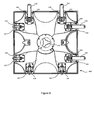
- FIG. 6 is a further illustration of an embodiment of the present disclosure showing the rear view of a single tile of a video display.
- Clips 162 on the edge of a tile connects to receptacles 164 on the adjacent tile.
- angle adjustment plate 167 will be pulled into contact with clamp plate 168 on the adjacent tile.
- Clip 162 is designed such that it can accommodate a wide range of angles in angle adjustment plate 167 and still maintain accurate and secure connection between the tiles.
- clips 162 on a further edge of a tile connect to receptacles 164 on the adjacent tile and angle adjustment plates 167 will be pulled into contact with clamp plate 168.
- Strength and support for tile 160 is provided through center attachment point 166 which connects to the interconnecting member back to the structural support.
- FIGS 7 and 8A-C show an embodiment of the present disclosure showing the rear view of a tile and the clamping assembly which ensures accurate alignment between adjacent tiles.
- Each clamp assembly includes a clip 162 and a receptacle 164.
- Each tile may have two sides with clips and two sides with receptacles.
- the clips 162 further include a hook 201 and an operating lever 163 connected to the body of the clip 205.
- the body of the clip 205 is securely attached to a tile 160.
- the receptacles include a retractable dowel 202 and a spring 203 (i.e., a biasing mechanism). Spring 203 connect the retractable dowel 202 to the body of the receptacle 204.
- the body of the receptacle 204 is securely attached to a tile 160.
- a tile 160 may be constructed with any number of clips on any number of sides without departing from the invention as defined in claim 1.
- a small tile may use only one clip on a side of the tile while larger tiles may include three or more clips.
- Figure 8A shows the first stage in the joining and alignment of two adjacent tiles A and B.
- Receptacle 204 in tile A is separated from and misaligned with clip 205 in the adjacent tile B.
- Retractable dowel 202 is pushed back by spring 203 into its resting position clear of the alignment hole 206 in receptacle 204.
- the spring is a compression spring which pushes or urges the retractable dowel away from alignment hole 206.
- Hook 201 from tile B is placed over the retractable dowel 202 in tile A.
- FIG 8B shows receptacle 204 and clip 205 aligned but still separated.
- Retractable dowel 202 is a precise tolerance fit into the two alignment holes 206 and 207, thus receptacle 204 and clip 205 are brought into accurate alignment in two planes defined by the retractable dowel 202 and alignment holes 206 and 207.
- hook 201 is free to move in at least two planes-both parallel and perpendicular to the axis of the retractable dowel and alignment holes.
- retractable dowel 202 may be constrained to move only in a single plane along its axis and thus can be a very high tolerance fit within alignment holes 206 and 207.
- This separation of the retractable dowel 202 from the pressure applying hook 201 further separates the high positional accuracy alignment components 202, 206, and 207 from the lower positional accuracy strength providing component 201. This ensures easy and simple assembly of the joint while still ensuring a high degree of accuracy of alignment as the hook 201 is unconstrained in its movement and may be brought into approximate position easily thus removing any necessity for retractable dowel 202 to have any freedom of movement off its main axis.
- Figure 8C shows the final locked and clamped position where hook 201 has fully engaged retractable dowel 202 and receptacle 204 and clip 205, and thus tiles A and B, aligned and abutting. Releasing the clamp follows the reverse process, as pressure on hook 201 is removed spring 203 will push retractable dowel 202 back out of alignment holes 206 and 207 thus disconnecting receptacle 204 from clip 205.
- the retractable dowel 202 further facilitates safely and simply removing or changing a tile in a display either during initial construction or when replacing a tile for maintenance.
- the procedure to install a tile may be as follows; firstly two adjacent tiles, A and B are roughly positioned with hooks 201 from Tile B positioned over retractable dowels 202 from Tile A. At this point tile B's weight is safely supported by hooks 201 with pressure being applied to the retractable dowels 202. The operator may now safely release the weight of the tile and is free to adjust its position such that apertures 206 and 207 are brought into alignment. As apertures 206 and 207 are aligned the retractable dowel 202 will be pushed through both apertures by the weight of the tile and will thus be in the correct position such that clamps may be closed securing the hook 201 and dowels 202.
- Removal is the reverse process, where the operating levers 163 are unlocked and released so that the spring 203 will push retractable dowels 202 out of the alignment holes 206 and 207.
- the full retraction of the dowels under spring pressure allows the tile to be removed from the display even if it is a central tile in situ with tiles surrounding it on all four sides. Thus any tile can be removed and replaced in a fully constructed display with no need to dismantle the display.
- Figure 7 also illustrates one embodiment of safety latches that ensure that operating lever 163 remains latched after assembly.
- safety latch 210 on receptacle 204 engages with a receptor 211 at the end of the operating lever 163.
- the engagement of the safety latch 210 is automatic as the operating lever is closed and prevents the accidental opening of the operating lever.
- an operator wishes to release the operating lever to separate the clamp he must first depress the safety latch 210 before lifting the operating lever 163.
- Figures 9 and 10 show a further embodiment of a safety latch that ensures that operating lever 163 remains latched after assembly.
- Figure 9 illustrates the system in its open and unlatched position.
- Safety latch 172 is pushed against the rear of operating lever 163 by spring 174 but a tab 171 and detent 173 are separated and do not engage.
- Figure 10 illustrates the closed and locked position. As operating lever 163 is rotated and closed tab 171 passes detent 173, this allows spring 174 to push safety latch 172 forwards. As safety latch 172 moves forwards detent 173 engages behind tab 171. In this position operating lever 163 is prevented from rotating by the engagement of tab 171 in detent 173 and is thus locked and unable to be opened accidentally.
- Figure 11 shows a back side of a display that is made up of one or more tiles such as shown in figure 5 .
- the tiles are identical.
- a tile, such as a first tile 1105 includes handles 1110, a first set of clips including hooks 1115a and 1115b, a second set of clips including hooks 1120a and 1120b, a first set of clip receptacles including retractable dowels 1125a and 1125b, and a second set of clip receptacles including retractable dowels 1130a and 1130b.
- the first tile interlocks with adjacent tiles via a clip on the first tile and a corresponding clip receptacle on an adjacent tile.
- the first tile is adjacent to a second tile 1150 which is above the first tile.
- Hooks 1115a and 1115b of the first tile hook onto retractable dowels 1152a and 1152b of the second tile.
- a portion of retractable dowels 1152a and 1152b of the second tile are forced (e.g., pushed or pulled towards) into dowel receptacles (or alignment holes) in the first set of clips of the first tile.
- the first and second tiles are then interlocked. That is, the dowel projects past an edge or side surface of the second tile, past an edge or side surface of the first tile, and into the dowel receptacle of the first tile.
- hooks of a third tile 1170 hook onto retractable dowels 1130a and 1130b of the first tile.
- the third tile is adjacent to (i.e., on a right-hand side of) the first tile.
- Hooks of a fourth tile 1180 hook onto dowels 1125a and 1125b of the first tile.
- the fourth tile is below the first tile.
- Hooks 1120a and 1120b of the first tile hook onto retractable dowels of a fifth tile 1190.
- the fifth tile is adjacent to (i.e., on a left-hand side of) the first tile.
- the first tile has a first, second, third, and fourth side.
- the second side is opposite the first side.
- the third side is opposite the fourth side.
- the first side is adjacent to the third and fourth sides.
- the second side is adjacent to the third and fourth sides.
- the first side includes the first set of clips (e.g., hooks 1115a and 1115b).
- the second side includes the first set of clip receptacles (e.g., retractable dowels 1125a and 1125b).
- the third side includes the second set of clip receptacles (e.g., retractable dowels 1130a and 1130b).
- the fourth side includes the second set of clips (e.g., hooks 1120a and 1120b).
- a side of a tile when a side of a tile has clips another side on the tile opposite the side has clip receptacles. When a side of a tile has clips another side adjacent to the side has clips. When a side of a tile has clip receptacles another side adjacent to the side has clip receptacles. In another implementation, when a side of a tile has clips another side on the tile opposite the side has clips. When a side of a tile has clip receptacles another side on the tile opposite the side has clip receptacles.
- a tile can have any number of handles such as no handles, one, three, four, or more than four handles.
- a user can grasp or hold the tile using their two hands.
- a left hand of the user can grasp one handle and a right hand of the user can grasp another handle.
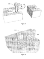
- Figure 12 shows the back side of the display where the first tile has been unclipped (e.g., unlocked, or disengaged) from the adjacent tiles.
- the first tile can be replaced (e.g., swapped or substituted) with a different tile without affecting the position of the other tiles in the display.
- the first tile is unclipped by unhooking the hooks around the first tile. This disengages the retractable dowels.
- the retractable dowels have been unfilled in figure 12 to indicate their disengaged state or position.
- the first tile is disengaged from the second tile by unhooking hooks 1115a and 1115b of the first tile from the clip receptacles (or retractable dowels) of the second tile.
- Retractable dowels 1152a and 1152b of the second tile are spring-loaded. The spring acts to urge the retractable dowels back into the tile as shown in the figure by the direction of the arrows next to each of the retractable dowels.
- the retractable dowels retract back into the first tile.
- no portion of retractable dowels 1152a and 1152b of the second tile extend into the first tile.
- a portion of the retractable dowels of the second tile may extend into the first tile after the hooks have been unhooked.
- hooks of third tile1170 are unhooked from retractable dowels 1130a and 1130b of the first tile and retractable dowels 1130a and 1130b retract into the first tile.
- Hooks of fourth tile 1180 are unhooked from retractable dowels 1125a and 1125b of the first tile and retractable dowels 1125a and 1125b retract into the first tile.
- Hooks 1120a and 1120b of the first tile are unhooked from the retractable dowels of fifth tile 1190 and the retractable dowels retract into the fifth tile.
- the user may then grasp the handles of the first tile to remove the first tile from the display.
- Figure 13 shows the back side of the display where the first tile has been removed from the display. This leaves an opening 1305 in the display. The tiles that were adjacent to the first tile remain in position in the display. Second tile 1150 does not drop into opening 1305 because the second tile is interlocked with at least one other tile adjacent to the second tile. For example, hooks on a top side of the second tile are engaged with the retractable dowels of a tile 1310.
- Figure 14A shows a perspective view of a specific implementation of a retractable dowel 1405 of a first tile in an engaged position.
- the retractable dowel is mounted on a sliding carrier 1410 within a clip receptacle 1415.
- the sliding carrier slides along a set of rails 1420 within the clip receptacle.
- a hook of a second tile pulls the carrier towards the second tile so that the dowel of the retractable dowel can be received by a dowel receptacle of the second tile.
- a surface 1422 of the retractable dowel is not coplanar with a side edge (or surface) 1430 of the tile. That is, surface 1422 extends past surface 1430.
- the sliding carrier may be spring loaded to urge the carrier and thus the retractable dowel away from the second tile and back into the clamp receptacle.
- the sliding carrier may include a locking mechanism to secure the retractable dowel to the carrier.
- the locking mechanism can have a lock and unlock position so that the retractable dowel can be replaced (i.e., replaced with an angle adjustment dowel).
- the movement of the retractable dowel is constrained to move in a single plane along its axis due to the rails.
- the movement of the retractable dowel may be along a first axis 1425 where the first axis parallel to a face of the tile or perpendicular to a side edge (or surface) 1430 of the tile.
- the retractable dowel moves along a single axis this allows the first and second tiles to be aligned properly as discussed above. That is, the first tile will not be offset from the second tile (e.g., offset down or offset up). This helps to present a cohesive image to the viewer.
- the carrier, retractable dowel, or both can move along another axis in addition to the first axis.
- Figure 14B shows another perspective view of retractable dowel 1405 mounted on sliding carrier 1410.
- the sliding carrier includes a back plate 1450. The hook of the second tile contacts the back plate to pull the sliding carrier from the clip receptacle towards the second tile.
- Figure 15A shows a perspective view of retractable dowel 1405 of the first tile in a disengaged position.
- the hook of the second tile (not shown) has been unlocked from the retractable dowel.
- the spring of the carrier is then free to urge the carrier and thus the retractable dowel back into the clip receptacle.
- surface 1422 of the retractable dowel when the retractable dowel is in the disengaged position, surface 1422 of the retractable dowel is not coplanar with surface 1430 of the tile. That is, surface 1422 is behind surface 1430.
- the dowel of the retractable dowel is similarly behind surface 1430.
- a portion of the retractable dowel extends past surface 1430.
- Figure 15B shows another perspective view of retractable dowel 1405 in a disengaged position.
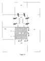
- Figure 16A shows a side view of a specific implementation of a clamp clip 1605 of a first tile 1607.
- the clamp clip includes an operating lever 1610 and a hook 1615 which interlocks with a clamp receptacle of a second tile 1620.
- a first shaft 1622 passes through the operating lever.
- a second shaft 1624 passes through the operating lever and the hook.
- the first and second shafts are in an offset arrangement.
- a first vertical axis passes through the first shaft.
- a second vertical axis passes through the second shaft.
- the first vertical axis is parallel with the second vertical axis.
- the first and second vertical axes are not coincident.
- the hook may move both parallel and perpendicular to the axis of the retractable dowel.
- the offset arrangement of the first and second shafts allow the hook to move in directions 1630 which are parallel to the movement of or the axis of the retractable dowel.
- Figure 16B shows a front view of clamp clip 1605.
- This view shows a front view of hook 1615 and second shaft 1624.
- a joint such as a ball and socket joint may be used to allow the hook to move in second directions 1652.
- a bushing e.g., compressible bushing between the hook and sides 1652 may be used to allow the hook to move in second directions 1652.
- a user assembles a video display using one or more tiles such as shown in figure 5 .
- the user can also easily reconfigure the video display by replacing a tile of the display (i.e., remove a tile from the display and insert another tile in the display).
- the tile to remove can be located anywhere or at any position in the display.
- the tile to be removed may be at a corner of the display. That is, the tile to be removed may have other tiles along its two adjacent sides.
- the tile to be removed may be on a side of the display. That is, the tile to be removed may have other tiles along its two adjacent sides and another tile opposite one of the adjacent sides.
- the tile to be removed may be surrounded by other tiles. That is, the tile to be removed may have other tiles on each side.
- a representative flow for replacing a tile of the video display is outlined in steps 1 to 4 below.
- the first tile of the display is unlocked from a position behind the display.
- the first tile may be unlocked or unclipped from one or more tiles that may be positioned adjacent to the first tile.
- the first tile is removed from the display.
- the first tile can be removed from behind the display.
- the removal includes grasping one or more handles on a back side of the first tile and pushing the tile away from the display. This leaves an opening in the display that was previously occupied by the first tile.
- the first tile is then tilted downwards or about a first axis passing through a center or reference point of the first tile.
- the first tile is then turned, twisted, or rotated about 45 degrees about a second axis, passing through the center of the first tile and orthogonal to the first axis.
- a bottom side or edge of the first tile is now aligned with a diagonal of the opening.
- the first tile can then be pulled through the opening because a length of the bottom side of the first tile is less than a length of the diagonal of the opening.
- step 3 the second tile is inserted in the opening.
- the second tile can be inserted from behind the display.
- the insertion is the reverse of step 2. That is, the second tile is tilted and rotated so that a top side of the second tile is aligned with the diagonal of the opening. The second tile can then be pushed through the opening because a length of the top side of the second tile is less than the length of the diagonal of the opening. The second tile can then be rotated about the first and second axes so that a back side of the second tile faces the opening. The second tile is then pulled towards the opening in the display.
- the second tile is locked.
- the second tile can be locked from behind the display.
- the second tile may be locked to one or more tiles adjacent to the second tile.
- the steps above are listed in a specific order, the steps may take place in any order, as desired and depending upon the specific application. There may be additional or other steps, which may replace one or more of the above steps. Certain steps may be repeated.
- the tile to be replaced is accessed from a front side of the display.
- the tile to be replaced does not have to pass through any openings of the display.
- the tile to be removed is pulled from the display-creating an opening in the display-without having to be pushed from the display, reoriented, and then pulled through the opening.
- the replacement tile does not have to be oriented to be pushed through the opening, reoriented, and then pulled towards the opening. Rather, in this specific implementation, the replacement tile is pushed onto the opening or positioned over or covering the opening and then locked into place.
- a video display includes a plurality of tiles.
- the video display has a first side (e.g., face, viewing side, display side, light-emitting side, or front side) and a second side (e.g., rear or back side), opposite the first side.
- a method to replace one or more tiles of the video display includes, from the second side, unlocking a first tile. From the second side, removing the first tile. And, from the second side, inserting or placing a second tile into an opening or over an opening created in the display by the removed first tile.
- the first tile can have along any of its borders a tile. These tiles can remain in place while the first tile is being replaced with the second tile.
- a video display includes a plurality of tiles, each tile occupying a position on a layout of the video display.
- a first tile to be replaced is in a first position of the layout.
- a second tile is adjacent to the first tile and is in a second position of the layout.
- the first tile can be replaced by a third tile while the second tile remains in the second position.
- the layout or arrangement of the tiles can be described as an array of rows and columns of tiles.
- the first position may be a second row, third column of the array.
- the method may include removing the first tile from the first position of the layout and inserting the third tile into the first position of the layout. During the removing the first tile, the second tile remains in the second position of the layout. During the inserting the third tile, the second tile remains in the second position of the layout.
- the first tile may also be adjacent to a fourth tile in a third position of the layout, a fifth tile in a fourth position of the layout, a sixth tile in a fifth position of the layout, or combinations of these.
- the fourth tile can remain in the third position
- the fifth tile can remain in the fourth position
- the sixth tile can remain in the fifth position.
- techniques of the invention can also apply to reorienting a tile instead of replacing the tile. For example, after the display is assembled a user may discover that a tile is upside down and needs to be reoriented. The tile to be reoriented can have along any of its borders another tile. These other tiles can remain in place while the tile is reoriented 180 degrees.
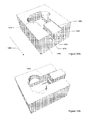
- Figure 17 shows a perspective view of a specific implementation of an angle adjustment dowel 1705 being inserted (as shown by arrow 1706) into a channel (e.g., cavity or groove) 1707 of a clamp receptacle 1710.
- the retractable dowel may be an angle adjustment dowel.
- the clamp receptacle is attached to a rear side of a tile (not shown).
- the figure also shows a dowel receptacle 1715 of a clamp clip 1720 which is partially shown in the figure.
- the clamp clip is attached to a rear side of an adjacent tile (not shown).
- the dowel receptacle receives a dowel 1725 of the angle adjustment dowel when the tile and the adjacent tile are connected (i.e., when the clamp receptacle of the tile is joined with the clamp clip of the adjacent tile as indicated by arrows 1726).
- a surface 1730 of the angle adjustment dowel from which the dowel projects has an angle 1735.
- the angle is shown measured in a counterclockwise direction from an x-axis 1740a where the x-axis indicates zero degrees and a y-axis 1740b indicates 90 degrees.
- the x-axis is parallel to a display side of the tile.
- the y-axis passes through the display side of the tile and is orthogonal to the display side. As shown in this example, the angle is greater than 90 degrees and less than 180 degrees.
- angle 1735 of surface 1730 may be about 100 degrees (as measured from the x-axis) and surface 1745 may be at a 90 degree angle.
- the desired angle is formed between the display sides of the tile and adjacent tile.
- the desired angle is about 190 degrees and a convex display is formed.
- Channel 1707 may be referred to as an angle adjustment dowel receptacle.
- These receptacles are formed on a rear side of the tile and extend through one or more side edges of the tile. As seen in the figure, when the angle adjustment dowel receptacle receives the angle adjustment dowel, the dowel points towards the side edge. The angle adjustment dowel can be replaced from a back side of the tile.
- Dowel 1725 may be referred to as an extension, stud, projection, peg, rod, or pin.
- the dowel can have any cross-sectional shape such as a circle, rectangle, square, star, triangle, pentagon, and so forth.
- Figure 18 shows another perspective view of angle adjustment dowel 1705 and surface 1730 from which dowel 1725 projects.
- the angle adjustment dowel (or block) includes a bottom edge 1850 and a side edge 1852.
- the bottom edge touches a bottom surface 1854 of the receptacle.
- the bottom edge is visible through an opening 1856 of a first side edge (or first side surface) of the tile.
- the first side of the tile includes the first side surface joining a front surface and a back surface of the tile.
- surface 1730 is not coplanar with the first side surface of the tile.
- Angle adjustment dowel 1705 may be replaced with angle adjustment dowel 2105 ( figures 21-22 ).
- angle adjustment dowel 2105 also has a bottom edge that touches the bottom surface of the receptacle.
- a side edge 2205 of angle adjustment dowel 2105 extends to the bottom edge. The side edge is adjacent to the bottom edge.
- side edge 2205 is visible through the opening at the first side edge and a surface from which the dowel of angle adjustment dowel 2105 projects from is planar with the first side surface of the tile.
- the tile may further include a second side edge, opposite of the first edge.
- the second side edge may have a second opening.
- the second opening may have a cross-sectional shape that is the same as (or different from) a cross-sectional shape of the dowel.
- the dowel projects orthogonally from surface 1730 or is normal to surface 1730.
- the dowel may project at a different angle from surface 1730.
- the angle adjustment dowel includes four fingers (e.g. guides, tabs, projections) 1810.
- the fingers are received by finger receptacles 1815 of clamp receptacle 1710. These fingers help ensure that the angle adjustment dowel is properly inserted into the clamp receptacle and help ensure that the angle adjustment dowel does not accidentally move or shift.
- the fingers are instead or additionally formed on the clamp receptacle and the finger receptacles are instead or additionally formed on the angle adjustment dowel.
- the angle adjustment dowel may be further secured to the clamp receptacle using a retaining mechanism incorporated into the clamp receptacle.
- the retaining mechanism may include components such as a spring, tab, notch, and lever. The user can push the lever against the force of the spring which moves a tab and allows the angle adjustment dowel to slide into the clamp receptacle. When the lever is released the spring may urge the tab into a notch in the angle adjustment dowel. The angle adjustment dowel is then locked into place so that it can not accidentally fall out. The user can remove the angle adjustment dowel by again pushing the lever to urge the tab out of the notch. The angle adjustment dowel is now unlocked and can be pulled from the clamp receptacle. For example, the user can insert their finger into a portion of the channel, pinch the angle adjustment dowel, and pull the angle adjustment dowel out. A new angle adjustment dowel can then be inserted by following a reverse procedure.
- the dowel and dowel receptacle can be used to help guide and align the interlocking of the tile and the adjacent tile.
- the dowel and dowel receptacle have circular cross sections. However, it should be appreciated that they can have any cross-sectional shape (e.g., square, rectangle, triangle, and so forth).
- the dowel can be located anywhere on surface 1730.
- the dowel receptacle can be located anywhere on surface 1745.
- the dowel and dowel receptacle are one example in accordance with the invention as defined in claim 1 of a structural interface between the clamp receptacle and clamp clip which interlock a tile and an adjacent tile.
- the structural interface may instead or additionally include a tongue and groove interface, a dovetail mating (i.e., a flaring tenon and a mortise into which it fits forming an interlocking joint), a ball and socket interface, and so forth.
- the angle adjustment dowel is accessible from a back side of the tile via the adjustment receptacle.
- the receptacle is visible on the back side and extends along a portion of the back side to a side surface of the tile (i.e., through an opening on the side surface).
- the angle adjustment dowel is instead accessible from the side surface of the tile.
- the angle adjustment dowel is not accessible from the back side. Rather, in this specific implementation, the angle adjustment dowel is inserted through the opening in the side surface of the tile.
- the receptacle may or may not be visible from the back side of the tile.
- Angle 1735 of the angle adjustment dowel can have any measurement so that any angle can be formed between the tile and an adjacent tile.
- Figure 19 shows a perspective view an angle adjustment dowel 1905 being inserted into clamp receptacle 1710.
- This angle adjustment dowel is similar to the angle adjustment dowel shown in figures 17-18 , but this angle adjustment dowel has a different angle.
- This angle adjustment dowel has an angle 1935 which as shown in the figure is less than 90 degrees as measured from x-axis 1740a.
- Figure 20 shows another perspective view of angle adjustment dowel 1905.
- Figure 21 shows a perspective view of an angle adjustment dowel 2105.
- This angle adjustment dowel is similar to the angle adjustment dowels shown in figures 17-18 and 19-20, but this angle adjustment dowel has a different angle.
- This angle adjustment dowel has an angle 2035 which as shown in the figure is about 90 degrees as measured from x-axis 1740a.
- Figure 22 shows another perspective view of angle adjustment dowel 2105.
- the angle adjustment dowels shown in figures 17-22 can have any angle. Depending on what type of display a user desires to create the user can select one or more angle adjustment dowels having a specific angle. The user can create planar, convex, or concave displays using the same tiles, but different angle adjustment dowels for each display type. Furthermore, combinations of different display types can be created. Using the tiles and angle adjustment dowels, displays resembling, for example, a bowl, pan, ball, sphere, ripples, or waves can be created. For example, a first portion of a display may have a concave arrangement of tiles. A second portion of the display may have a convex arrangement of tiles.
- a user assembles a video display using one or more tiles such as shown in figure 5 .
- the user can create any desired angle or curvature between two tiles by selecting the appropriate angle adjustment dowel and replacing (i.e., swapping or substituting) an old angle adjustment dowel.
- a representative flow for changing the angle between two tiles is outlined in steps 1 to 4 below.
- the tile is unlocked and removed from the display.
- the tile may be unlocked by unclamping a first clamp portion of the tile from a second clamp portion of an adjacent tile. The tile can then be removed or pulled from the display.
- a first angle adjustment dowel is removed from the tile.
- the first angle adjustment dowel may be removed by pulling the first angle adjustment dowel from a cavity (e.g., hole, slot, opening, space, hollow, aperture, notch, or groove) in the first clamp portion.
- Figure 23 shows a perspective view of removing first angle adjustment dowel 2305 from a rear (or back or nondisplay) side 2310 of a tile 2315.
- a face or surface 2320 of the first angle adjustment dowel may be perpendicular to a front or display side 2325 of the tile or may be at some other angle.
- the display side lies on a first plane.
- Surface 2320 lies on a second plane. The first and second planes intersect at a 90-degree angle.
- a first angle 2330 of the first angle adjustment dowel may be measured from the display side to surface 2320.
- step 3 a second angle adjustment dowel is inserted into the tile, i.e., inserted into the now empty cavity of the first clamp portion.
- Figure 24 shows a perspective view of inserting the second angle adjustment dowel into the tile.
- a second angle 2430 of the second angle adjustment dowel is measured from the display side to a surface 2440 of the second angle adjustment dowel. As seen in figures 23-24 , the second angle is different from the first angle.
- the inserts, cavity, or both may have a keying feature to help ensure that the insert is inserted properly into the cavity.
- the keying feature prevents the incorrectly oriented insert from being placed into the cavity.
- the insert, cavity, or both may have a locking feature so that the insert does not accidentally fall out when the tile is removed.
- the locking feature may be a magnet, a snap-fit mechanism between the insert and cavity, friction between the surfaces of the cavity and insert, and the like.
- step 4 the tile is placed back into the display.
- the tile may have two or more clamps that each need to be unlocked. Some of the two or more clamps may each have an angle adjustment dowel to be replaced. Some of the two or more clamps may have the same angle adjustment dowel (i.e., having same angles). Some of the two or more clamps may have different angle adjustment dowels (i.e., having different angles).
- a third angle 2350 is measured from the display side to a side (or side edge) 2355 of the tile.
- a tile in a specific implementation, includes a display side and a side. The side is at a third angle with respect to the display side.
- the tile further includes a first angle adjustment dowel.
- the first angle adjustment dowel is at a first angle with respect to the display side.
- the first angle is the same as the third angle. In another implementation, the first angle is different from the third angle.
- a method includes replacing the first angle adjustment dowel with a second angle adjustment dowel.
- the second angle adjustment dowel is at a second angle with respect to the display side.
- the second angle is different from the first angle.
- the second angle is different from the third angle.
- the angle adjustment dowel in the tile is pushed or pulled towards the adjacent tile when the tile and adjacent tile are joined.
- the angle adjustment dowel is pulled by the force of the clamp clip or hook on the adjacent tile.
- the angle adjustment dowel in the tile slides (e.g., slides on a track) towards the adjacent tile so that the angle adjustment dowel can butt up against the adjacent tile; and so that the dowel receptacle in the adjacent tile can receive the dowel.
- the angled surface of the angle adjustment dowel (or a portion of the surface) will protrude past the side of the tile in order to meet a side of the adjacent tile.
- the dowel (or a portion of the dowel) will protrude past the side of the tile in order to pass into the dowel receptacle in the adjacent tile.
- the clamp is then locked.
- the angle adjustment dowel is under the force of a spring.
- the spring urges the angle adjustment dowel away from the adjacent tile.
- the spring causes the angle adjustment dowel to retract into the tile (i.e., away from the adjacent tile).
- the angle adjustment dowel may retract at such a distance into the channel of the tile that the dowel, the surface from which the dowel projects, or both do not project past the side of the tile. This can help prevent the angled adjustment dowel from snagging (e.g., prevent the dowel from snagging on a wire).
- the angle adjustment dowel of a tile does not project past a side of the tile.
- a portion of the angle adjustment dowel projects past the side of the tile.
- the portion may project or be received by a receptacle (i.e., dowel receptacle) in an adjacent tile.
- a distance D1 indicates a length of the tile.
- a distance D2 indicates a width of the angle adjustment dowel or channel in the clamp portion that receives the angle adjustment dowel.
- a distance D3 indicates a position of the angle adjustment dowel (or channel) along the length of the tile. As shown in the figure, distance D3 is measured from an edge (e.g., top edge) of the tile to the angle adjustment dowel.
- a ratio of D2 to D1 is about 1:22.6.
- Other examples of the ratio include 1:15, 1:16, 1:17, 1:18, 1:19, 1:20, 1:21.5, 1:21.6, 1:21.7, 1:21.8, 1:21.9, 1:22, 1:22.1, 1:22.2, 1:22.3, 1:22.4, 1:22.5, 1:22.7, 1:22.8, 1:22.9, 1:23, 1:23.1, 1:23.2, 1:23.3, 1:23.4, 1:23.5, 1:24, 1:25, 1:26, 1:27, 1:28, 1:29, and 1:30.
- a wider D2 offers more support and a greater area of surface contact between the angle adjustment dowel of a tile and the surface of an adjacent tile as compared to a narrower D2. A greater area of surface contact between the tiles can create a stiffer display.
- a wider D2 may require additional material as compared to a narrower D2.
- a narrower D2 i.e., a narrower angle adjustment dowel
- the angle adjustment dowel is positioned about one fifth down from the edge of the tile. That is, D3 is about 20 percent of D1, but can range from about 10 percent of D1 to about 50 percent of D1 (i.e., halfway down the tile). For example, D3 may be about 15, 25, 30, 35, 40, 45 percent, or more than 50 percent of D1. In other implementations D3 is less than 10 percent of D1.
- the angle adjustment dowel may be positioned anywhere along the side of the tile. For example, the angle adjustment dowel may be positioned one-fourth, one-third, or one-half (i.e., in the middle) down the side of the tile.
- a video display includes a plurality of tiles.
- a first angle is between a first tile and a second tile.
- a method to change the first angle includes removing the first tile from the display. Removing a first angled insert having a second angle from the first tile. Inserting a second angled insert having a third angle, different from the second angle, into the first tile. Placing the first tile back into the display.
- a fourth angle, different from the first angle, is now between the first and second tiles.
- a tile can have any number of angled inserts on any side of the tile and have any angle. This allows, for example, the creation of a video display that curves in multiple directions or dimensions such as a sphere (or a portion of a sphere) or a bowl (or a portion of a bowl).
- a user can change one or more angled inserts of a tile to vary the curvature or degree of curvature of the video display.
- a display can have a varying degree of curvature. For example, a degree of curvature for a portion of the display may be different from a degree of curvature for another portion of the display. In other words, the display can have increasing radii, decreasing radii, or both.
- angled inserts of a tile may not be replaced while other angled inserts of the tile are replaced.
- An angled insert of a tile may be switched from one side of the tile to another side (e.g., opposite side or adjacent side) of the tile.
- method for changing a curvature of a video display having a plurality of tiles includes removing a tile from the display.
- the tile includes a first plurality of angled inserts.
- a first insert having a first angle is located on a first side (e.g., right-hand side) of the tile.
- a second insert having a second angle is located on the first side.
- the first and second angles may be the same or different.
- the method includes replacing the first insert with a third insert having a third angle and replacing the second insert with a fourth insert having a fourth angle.
- the third and fourth angles may be the same or different.
- the first angle may be the same or different from the third angle.
- the second angle may be the same or different from the fourth angle.
- the second insert may instead be located on a second side (e.g., left-hand side) of the tile.
- the second side of the tile may be opposite the first side or adjacent to the first side (e.g., bottom side or top side).
- angled inserts of two or more tiles of a display are changed to change the curvature of the display.
- the method includes removing a first tile from the display. Replacing a first angled insert having a first angle in the first tile with a second angled insert having a second angle, different from the first angle. Removing a second tile from the display. Replace a third angled insert having a third angle in the second tile with a fourth angled insert having a fourth angle, different from the third angle. Inserting the first and second tiles back into the display.
- a tile has two angle adjustment dowels on one side and two angle adjustment dowels on an adjacent side.
- a tile can have any number of angle adjustment dowels.
- a tile can have angle adjustment dowels having a first angle on a first side of the tile.
- the tile can have angle adjustment dowels having a second angle on a second side of the tile.
- the first and second angles may be the same or different.
- the first side may be opposite the second side.
- the first side may be a top side and the second side may be a bottom side.
- the first side may be a left-hand side and the second side may be a right-hand side.
- the first and second sides may be adjacent.
- the first side may be a top side and the second side may be a right-hand side or a left-hand side.
- angle adjustment dowels are received by both the clamp receptacle and the clamp clip.
- the angle adjustment dowel received by the clamp receptacle may have an angle that is different or the same as the angle of the angle adjustment dowel received by the clamp clip.
- An angle adjustment dowel may be received by the clamp clip, but not the clamp receptacle.
- the angle adjustment dowels are included with the tiles when the tiles are purchased.
- the angle adjustment dowels are not included with the tiles and must be purchased separately.
- the angle adjustment dowels are included in a kit of angle adjustment dowels. The kit may be purchased separately from the tiles.
- first and second angle adjustment dowels are fitted to first and second halves (e.g., sides, parts, or portions) of a clamp, respectively, have supplementary angles or angles such that when the first and second halves of the clamp are pulled together, a planar display is formed as shown, for example, in figure 8 .
- the first and second angle adjustment dowels can have any angle so long as the first and second tiles, when brought together, form a 180 degree angle with respect to the viewing or display side.
- first and second angle adjustment dowels have angles such that when the first and second halves of the clamp are pulled together, an angle between the first and second tile is greater than 180 degrees as shown, for example, in figures 10 and 14 to produce a convex nonplanar display.
- first and second angle adjustment dowels have angles such that when the first and second halves of the clamp are pulled together, an angle between the first and second tiles is less than 180 degrees as shown, for example, in figures 12 and 16 to produce a concave nonplanar display.
- the first and second angle adjustment dowels can have any angle (e.g., 0, 5, 10, 15, 20, 25, 35, 45, 60, 90, or 135 degrees, and so forth).
- the angles may be supplementary as discussed or complementary (i.e., sum of their measures is 90 degrees).
- An angle can be acute (i.e., less than 90 degrees) or obtuse (i.e., between 90 degrees and 180 degrees).
Landscapes
- Engineering & Computer Science (AREA)
- Theoretical Computer Science (AREA)
- Physics & Mathematics (AREA)
- General Physics & Mathematics (AREA)
- General Engineering & Computer Science (AREA)
- Multimedia (AREA)
- Human Computer Interaction (AREA)
- Spectroscopy & Molecular Physics (AREA)
- Devices For Indicating Variable Information By Combining Individual Elements (AREA)
- Control Of Indicators Other Than Cathode Ray Tubes (AREA)
- Illuminated Signs And Luminous Advertising (AREA)
- Non-Portable Lighting Devices Or Systems Thereof (AREA)
- Fastening Of Light Sources Or Lamp Holders (AREA)
Claims (8)
- Système d'affichage électroluminescent (112, 114, 116, 118) qui comprend :un premier pavé électroluminescent qui possède une pluralité d'éléments électroluminescents (101a, 101b, 101c, 101d) disposés dessus, et un premier élément de liaison (163, 201, 1115a) relié de manière adjacente à un bord de celui-ci ; etun second pavé électroluminescent qui possède une pluralité d'éléments électroluminescents (101a, 101b, 101c, 101d) disposés dessus, et un second élément de liaison (204, 210, 1152a) relié de manière adjacente à un bord de celui-ci, le premier élément de liaison (163, 201, 1115a) étant configuré pour être relié au second élément de liaison (204, 210, 1152a) de sorte qu'un côté du premier pavé électroluminescent bute contre un côté du second pavé électroluminescent,le premier élément de liaison (163, 201, 1115a) étant configuré pour être relié de manière amovible au second élément de liaison, le premier élément de liaison comprenant une fixation (163, 201, 1115a), et le second élément de liaison comprenant un réceptacle (204, 210, 1152a), et la fixation comprenant un crochet (201) et un levier (163), et le réceptacle comprenant un goujon (202), le levier étant configuré pour engager le crochet, le crochet étant configuré pour engager le goujon, et le goujon étant rétractable,dans lequel le crochet (201), le levier (163) et le goujon (202) sont chacun configurés pour être mobiles entre une position engagée et une position non engagée,dans lequel le réceptacle comprend en outre un mécanisme d'inclinaison (203) disposé de manière adjacente au goujon (202) et reliant le goujon au corps du réceptacle (204),dans lequel, en position engagée, le levier (163) engage le crochet (201) de sorte que le crochet (201) exerce une force sur le goujon (202), et que le goujon engage ensuite un trou d'alignement (206) formé dans le réceptacle (204), etdans lequel, en position engagée, le mécanisme d'inclinaison (203) incline le goujon vers la position non engagée, à l'écart du trou d'alignement (206) dans le réceptacle (204).
- Système d'affichage selon la revendication 1, dans lequel une plaque de réglage (167) est disposée de manière adjacente à l'un de la fixation (163, 201, 1115a) et du réceptacle (204, 210, 1152a).
- Système d'affichage selon la revendication 1, dans lequel la fixation (163, 201, 1115a) est reliée de manière adjacente à un bord du premier pavé électroluminescent, le réceptacle (204, 210, 1152a) étant relié de manière adjacente à un bord du second pavé électroluminescent.
- Système d'affichage selon la revendication 1, dans lequel la force du crochet (201) s'oppose à la force d'inclinaison du mécanisme d'inclinaison (203).
- Système d'affichage selon la revendication 1, qui comprend en outre un verrou de sécurité (210).
- Système d'affichage selon la revendication 1, dans lequel le goujon rétractable est libre de coulisser dans le réceptacle du second pavé électroluminescent.
- Système d'affichage selon la revendication 1, dans lequel le goujon rétractable est contraint de se déplacer uniquement sur un seul plan le long de son axe par rapport au premier pavé électroluminescent.
- Système d'affichage selon la revendication 1, dans lequel le goujon rétractable est poussé vers l'arrière dans le réceptacle.
Applications Claiming Priority (8)
| Application Number | Priority Date | Filing Date | Title |
|---|---|---|---|
| US6136908P | 2008-06-13 | 2008-06-13 | |
| US6133808P | 2008-06-13 | 2008-06-13 | |
| US6136508P | 2008-06-13 | 2008-06-13 | |
| US6135308P | 2008-06-13 | 2008-06-13 | |
| US6134708P | 2008-06-13 | 2008-06-13 | |
| US6135808P | 2008-06-13 | 2008-06-13 | |
| US12/484,205 US8197088B2 (en) | 2008-06-13 | 2009-06-13 | Vertical handling apparatus for a display |
| PCT/US2009/047418 WO2009152524A2 (fr) | 2008-06-13 | 2009-06-15 | Appareil de manutention verticale pour un afficheur |
Publications (3)
| Publication Number | Publication Date |
|---|---|
| EP2304711A2 EP2304711A2 (fr) | 2011-04-06 |
| EP2304711A4 EP2304711A4 (fr) | 2012-01-25 |
| EP2304711B1 true EP2304711B1 (fr) | 2016-01-06 |
Family
ID=41414276
Family Applications (2)
| Application Number | Title | Priority Date | Filing Date |
|---|---|---|---|
| EP09763811.8A Not-in-force EP2304711B1 (fr) | 2008-06-13 | 2009-06-15 | Système d'affichage électroluminescent formé par plusieurs afficheurs |
| EP09763813A Ceased EP2301008A4 (fr) | 2008-06-13 | 2009-06-15 | Système d'étalonnage de couleur pour un dispositif d'affichage vidéo |
Family Applications After (1)
| Application Number | Title | Priority Date | Filing Date |
|---|---|---|---|
| EP09763813A Ceased EP2301008A4 (fr) | 2008-06-13 | 2009-06-15 | Système d'étalonnage de couleur pour un dispositif d'affichage vidéo |
Country Status (3)
| Country | Link |
|---|---|
| US (12) | US9400212B2 (fr) |
| EP (2) | EP2304711B1 (fr) |
| WO (4) | WO2009152526A2 (fr) |
Families Citing this family (123)
| Publication number | Priority date | Publication date | Assignee | Title |
|---|---|---|---|---|
| US7995098B2 (en) * | 2005-09-09 | 2011-08-09 | Radiant Imaging, Inc. | Systems and methods for measuring spatial and angular performance of a visual display |
| US12086498B2 (en) | 2008-01-04 | 2024-09-10 | Nanolumens Acquisition, Inc. | Display system and methods |
| US9071809B2 (en) | 2008-01-04 | 2015-06-30 | Nanolumens Acquisition, Inc. | Mobile, personsize display system and method of use |
| US9400212B2 (en) | 2008-06-13 | 2016-07-26 | Barco Inc. | Smart pixel addressing |
| US20100214282A1 (en) | 2009-02-24 | 2010-08-26 | Dolby Laboratories Licensing Corporation | Apparatus for providing light source modulation in dual modulator displays |
| US10146369B2 (en) * | 2010-08-19 | 2018-12-04 | Novatek Microelectronics Corp. | Electronic apparatus with touch panel and method for updating touch panel |
| TWI401593B (zh) * | 2010-08-19 | 2013-07-11 | Novatek Microelectronics Corp | 具有觸控面板的電子裝置及觸控面板更新方法 |
| IT1401694B1 (it) * | 2010-09-10 | 2013-08-02 | Clay Paky Spa | Schermo a led |
| WO2014004788A1 (fr) * | 2012-06-28 | 2014-01-03 | Hemiller Ryan | Montage de module d'affichage |
| AU2013280215B2 (en) | 2012-06-28 | 2017-03-30 | Daktronics, Inc. | Display module mounting |
| US8974077B2 (en) | 2012-07-30 | 2015-03-10 | Ultravision Technologies, Llc | Heat sink for LED light source |
| KR102118309B1 (ko) | 2012-09-19 | 2020-06-03 | 돌비 레버러토리즈 라이쎈싱 코오포레이션 | 양자점/리모트 인광 디스플레이 시스템 개선 |
| CN202939922U (zh) * | 2012-10-16 | 2013-05-15 | 深圳市奥拓电子股份有限公司 | 一种显示屏快速拼接装置 |
| CZ25154U1 (cs) * | 2012-11-14 | 2013-04-02 | Esofia S.R.O. | Segmentová digitální zobrazovací plocha provedená jako digitální tapeta |
| US9476575B2 (en) * | 2013-03-04 | 2016-10-25 | Revolution Display, Llc | Video display module support assembly |
| EP2965308B1 (fr) | 2013-03-08 | 2020-09-09 | Dolby Laboratories Licensing Corporation | Techniques pour l'affichage de modulation double à conversion de lumière |
| PL2815695T3 (pl) | 2013-06-20 | 2019-10-31 | Erbe Elektromedizin | Instrument chirurgiczny z rozpoznawaniem tkanki |
| CN103438061B (zh) * | 2013-09-06 | 2016-04-06 | 利亚德光电股份有限公司 | 连接装置及具有其的led显示单元 |
| US9601061B2 (en) * | 2013-11-01 | 2017-03-21 | Sergio Lara Pereira Monteiro | Method and means to prevent dark lines within the image space of lighted billboards and other public display devices |
| US9195281B2 (en) | 2013-12-31 | 2015-11-24 | Ultravision Technologies, Llc | System and method for a modular multi-panel display |
| CN111243533B (zh) * | 2014-03-26 | 2022-11-25 | 杜比实验室特许公司 | 各种显示器中的全局光补偿 |
| JP2015200710A (ja) * | 2014-04-04 | 2015-11-12 | パナソニック株式会社 | 表示装置取付金具および表示装置取付治具 |
| US10030853B2 (en) * | 2014-06-13 | 2018-07-24 | Martin Professional Aps. | LED screen comprising spring retainers for LED modules |
| US9144140B1 (en) | 2014-08-12 | 2015-09-22 | Electronic Theatre Controls, Inc. | System and method for controlling a plurality of light fixture outputs |
| US9713222B2 (en) | 2014-08-12 | 2017-07-18 | Electronic Theatre Controls, Inc. | System and method for controlling a plurality of light fixture outputs |
| CN108873477B (zh) | 2014-08-21 | 2021-08-17 | 杜比实验室特许公司 | 用于驱动局部调光显示器的方法、设备和存储介质 |
| US9880799B1 (en) * | 2014-08-26 | 2018-01-30 | Sprint Communications Company L.P. | Extendable display screens of electronic devices |
| WO2016061223A1 (fr) * | 2014-10-14 | 2016-04-21 | Corey Barkhurst | Systèmes modulaires d'éclairage de travées et procédés de fourniture d'éclairage |
| CN104407464A (zh) * | 2014-12-09 | 2015-03-11 | 京东方科技集团股份有限公司 | 一种拼接显示器及显示系统 |
| WO2016109439A1 (fr) * | 2014-12-29 | 2016-07-07 | Planar Systems, Inc. | Support avec positionnement caché à actionnement magnétique |
| KR102272059B1 (ko) | 2015-02-09 | 2021-07-05 | 삼성전자주식회사 | 디스플레이 모듈 및 이를 포함하는 디스플레이 장치 |
| EP3054273B8 (fr) * | 2015-02-09 | 2019-09-11 | Instrument Systems Optische Messtechnik GmbH | Système de colorimétrie pour test d'affichage |
| EP3062142B1 (fr) | 2015-02-26 | 2018-10-03 | Nokia Technologies OY | Appareil pour un dispositif d'affichage proche |
| CN104749112B (zh) * | 2015-04-06 | 2017-02-22 | 河北工业大学 | 一种发光光谱虚拟led效果的方法 |
| CA2990955A1 (fr) * | 2015-07-01 | 2017-01-05 | ACASS Systems LLC | Systeme d'affichage a verrouillage mutuel modulaire |
| CN105025277A (zh) * | 2015-07-24 | 2015-11-04 | 大连集思特科技有限公司 | Led显示屏光纤传输系统 |
| KR102423350B1 (ko) | 2015-08-04 | 2022-07-22 | 삼성전자 주식회사 | 복수의 모듈을 포함하는 디스플레이장치 및 그 제어방법 |
| US9864561B2 (en) | 2015-09-25 | 2018-01-09 | Revolution Display, Llc | Devices for creating mosaicked display systems, and display mosaic systems comprising same |
| US9477438B1 (en) | 2015-09-25 | 2016-10-25 | Revolution Display, Llc | Devices for creating mosaicked display systems, and display mosaic systems comprising same |
| KR101705508B1 (ko) * | 2015-10-08 | 2017-02-13 | 주식회사 에이블테크 | 디스플레이 장치 |
| HK1218227A2 (zh) * | 2015-11-20 | 2017-02-03 | PanelOled Ltd. | 一种照明面板以及一种照明系统 |
| US10672306B1 (en) * | 2016-03-18 | 2020-06-02 | Totally Mod Events, Llc | Modular display assembly and related components and methods of use |
| US9877406B2 (en) | 2016-06-13 | 2018-01-23 | Revolution Display, Llc | Architectural panel system composed of a combination of sensory output tile modules and non-sensory-output tile modules, and components therefor |
| USD771844S1 (en) | 2016-06-22 | 2016-11-15 | Revolution Display, Llc | LED module |
| KR102519930B1 (ko) * | 2016-07-07 | 2023-04-11 | 삼성전자주식회사 | 디스플레이 장치 |
| US11022494B2 (en) * | 2016-07-14 | 2021-06-01 | Commonwealth Scientific and Indsutrial Research Organisation | Apparatus for measuring spectra |
| US10531581B2 (en) * | 2016-10-28 | 2020-01-07 | Lg Electronics Inc. | Display apparatus |
| RU170852U1 (ru) * | 2016-11-30 | 2017-05-11 | Общество с ограниченной ответственностью "СТЭП ЛОДЖИК" (ООО "СТЭП ЛОДЖИК") | Устройство крепления сегментов видеостены мобильного комплекса системы наглядного отображения информации быстрого развертывания (мк снои) |
| GB201620544D0 (en) * | 2016-12-02 | 2017-01-18 | Barco Nv | Front maintenance apparatus for flexible tiled LED display |
| US10650552B2 (en) | 2016-12-29 | 2020-05-12 | Magic Leap, Inc. | Systems and methods for augmented reality |
| EP3343267B1 (fr) | 2016-12-30 | 2024-01-24 | Magic Leap, Inc. | Appareil de découplage de lumière polychromatique, affichages proches de l' il le comprenant et procédé de découplage de lumière polychromatique |
| US10578870B2 (en) | 2017-07-26 | 2020-03-03 | Magic Leap, Inc. | Exit pupil expander |
| US11074028B2 (en) | 2017-07-26 | 2021-07-27 | Barco N.V. | Calibration method and system for tiled displays |
| WO2019034786A1 (fr) | 2017-08-18 | 2019-02-21 | Barco N.V. | Structure de support réglable pour pavé d'affichage |
| CN207367529U (zh) * | 2017-11-10 | 2018-05-15 | 深圳市洲明科技股份有限公司 | Led显示装置的拼接结构 |
| JP7282090B2 (ja) | 2017-12-10 | 2023-05-26 | マジック リープ, インコーポレイテッド | 光学導波管上の反射防止性コーティング |
| CN111712751B (zh) | 2017-12-20 | 2022-11-01 | 奇跃公司 | 用于增强现实观看设备的插入件 |
| KR102481264B1 (ko) * | 2018-01-04 | 2022-12-26 | 삼성전자주식회사 | 디스플레이 장치 및 디스플레이 모듈의 힌지 조립체 |
| CN207883225U (zh) * | 2018-02-13 | 2018-09-18 | 南京洛普科技有限公司 | 一种双曲面弧形显示屏 |
| EP4415355A3 (fr) | 2018-03-15 | 2024-09-04 | Magic Leap, Inc. | Correction d'image due à la déformation de composants d'un dispositif de visualisation |
| DE102018108551B3 (de) * | 2018-04-11 | 2019-09-05 | HARTING Electronics GmbH | LED-Panel |
| US10896630B2 (en) * | 2018-04-27 | 2021-01-19 | Ronnie R. Boswell | Rapidly-deployable configurable, modular light emitting diode (LED) sign system |
| JP7650662B2 (ja) | 2018-05-30 | 2025-03-25 | マジック リープ, インコーポレイテッド | 小型の可変焦点構成 |
| CN112601975B (zh) | 2018-05-31 | 2024-09-06 | 奇跃公司 | 雷达头部姿势定位 |
| US10825424B2 (en) | 2018-06-05 | 2020-11-03 | Magic Leap, Inc. | Homography transformation matrices based temperature calibration of a viewing system |
| JP7421505B2 (ja) | 2018-06-08 | 2024-01-24 | マジック リープ, インコーポレイテッド | 自動化された表面選択設置およびコンテンツ配向設置を用いた拡張現実ビューア |
| WO2020010097A1 (fr) | 2018-07-02 | 2020-01-09 | Magic Leap, Inc. | Modulation d'intensité de pixel en utilisant la modification de valeurs de gain |
| US11510027B2 (en) | 2018-07-03 | 2022-11-22 | Magic Leap, Inc. | Systems and methods for virtual and augmented reality |
| US11856479B2 (en) | 2018-07-03 | 2023-12-26 | Magic Leap, Inc. | Systems and methods for virtual and augmented reality along a route with markers |
| JP7374981B2 (ja) | 2018-07-10 | 2023-11-07 | マジック リープ, インコーポレイテッド | クロス命令セットアーキテクチャプロシージャ呼出のためのスレッドウィービング |
| US11598651B2 (en) | 2018-07-24 | 2023-03-07 | Magic Leap, Inc. | Temperature dependent calibration of movement detection devices |
| WO2020023543A1 (fr) | 2018-07-24 | 2020-01-30 | Magic Leap, Inc. | Dispositif de visualisation à intégrant un joint anti-poussière |
| EP4650919A3 (fr) | 2018-08-02 | 2026-01-21 | Magic Leap, Inc. | Système de visualisation avec compensation de distance interpupillaire sur la base du mouvement de la tête |
| EP3830631A4 (fr) | 2018-08-03 | 2021-10-27 | Magic Leap, Inc. | Correction de dérive basée sur une pose non fusionnée d'une pose fusionnée d'un totem dans un système d'interaction d'utilisateur |
| CN112534225B (zh) * | 2018-08-03 | 2024-05-14 | 奇跃公司 | 光学显示器的led热特性表征和校准 |
| AT521532B1 (de) * | 2018-08-14 | 2020-04-15 | Reintechnik Gmbh | Haltevorrichtung für Video-Wände |
| JP7487176B2 (ja) | 2018-08-22 | 2024-05-20 | マジック リープ, インコーポレイテッド | 患者視認システム |
| KR102550294B1 (ko) * | 2018-09-28 | 2023-07-04 | 엘지디스플레이 주식회사 | 멀티디스플레이의 갭 조절장치 및 이를 갖는 멀티디스플레이 |
| CN113196138B (zh) | 2018-11-16 | 2023-08-25 | 奇跃公司 | 用于保持图像清晰度的图像尺寸触发的澄清 |
| CN111243445B (zh) * | 2018-11-29 | 2023-09-05 | 巴科股份有限公司 | 针对拼接式显示器的拼接块的对齐 |
| CN109448562B (zh) * | 2018-12-11 | 2024-02-23 | 深圳市齐普光电子股份有限公司 | 一种联动模块化led显示模组 |
| JP7543274B2 (ja) | 2018-12-21 | 2024-09-02 | マジック リープ, インコーポレイテッド | 導波管内の全内部反射を助長するための空気ポケット構造 |
| KR102599722B1 (ko) * | 2018-12-28 | 2023-11-09 | 삼성디스플레이 주식회사 | 표시 패널 및 이를 포함하는 타일드 표시 장치 |
| JP7515489B2 (ja) | 2019-02-06 | 2024-07-12 | マジック リープ, インコーポレイテッド | 複数のプロセッサによって発生される総熱を限定するための標的意図ベースのクロック速度の決定および調節 |
| GB201901729D0 (en) * | 2019-02-07 | 2019-03-27 | Barco Nv | System and method for mounting of polygonal display wall |
| EP3705989A1 (fr) | 2019-03-07 | 2020-09-09 | Stereyo BVBA | Affichage transparent et déformable en temps réel |
| EP3939030B1 (fr) | 2019-03-12 | 2025-10-29 | Magic Leap, Inc. | Enregistrement d'un contenu local entre des premier et second visualiseurs de réalité augmentée |
| CN120812326A (zh) | 2019-05-01 | 2025-10-17 | 奇跃公司 | 内容提供系统和方法 |
| EP4679407A3 (fr) | 2019-06-07 | 2026-04-29 | Stereyo BV | Procédé d'optimisation de la plage dynamique d'un écran à del |
| WO2021021670A1 (fr) | 2019-07-26 | 2021-02-04 | Magic Leap, Inc. | Systèmes et procédés de réalité augmentée |
| US11929602B2 (en) * | 2019-10-23 | 2024-03-12 | Cable Management Solutions Inc. | Cable conveyance systems incorporating electronic visual displays |
| US11244843B2 (en) * | 2019-10-25 | 2022-02-08 | Tcl China Star Optoelectronics Technology Co., Ltd | Fixing device and method of manufacturing display panel |
| US12033081B2 (en) | 2019-11-14 | 2024-07-09 | Magic Leap, Inc. | Systems and methods for virtual and augmented reality |
| EP4058979A4 (fr) | 2019-11-15 | 2023-01-11 | Magic Leap, Inc. | Système de visualisation à utiliser dans un environnement chirurgical |
| WO2021118556A1 (fr) | 2019-12-11 | 2021-06-17 | Google Llc | Étalonnage de couleur de modules d'affichage à l'aide d'un nombre réduit de mesures de caractéristiques d'affichage |
| US11011084B1 (en) * | 2020-02-04 | 2021-05-18 | Christie Digital Systems Usa, Inc. | Modular mounting system |
| CN111261051B (zh) * | 2020-03-11 | 2021-09-07 | 山东锦霖智能科技集团有限公司 | 一种拼接显示屏 |
| KR102902104B1 (ko) * | 2020-07-21 | 2025-12-19 | 엘지전자 주식회사 | 디스플레이 장치 |
| TWI746083B (zh) * | 2020-07-24 | 2021-11-11 | 聯陽半導體股份有限公司 | 訊號中繼系統 |
| TWI740617B (zh) * | 2020-08-19 | 2021-09-21 | 智崴資訊科技股份有限公司 | 曲面顯示模組 |
| KR102404360B1 (ko) * | 2020-10-23 | 2022-06-02 | 엘지전자 주식회사 | 디스플레이 제어 모듈 및 이를 포함하는 디스플레이 장치 |
| KR102951387B1 (ko) * | 2020-12-30 | 2026-04-09 | 엘지디스플레이 주식회사 | 표시 장치 |
| US20220289095A1 (en) * | 2021-03-10 | 2022-09-15 | Craig Schreiber | Frontloading Enclosure utilizing Both a Primary Magnetic Connection System and a Secondary Constant-tension Resistance System. |
| CN113576209B (zh) * | 2021-08-02 | 2022-05-27 | 重庆商务职业学院 | 一种电商网络直播用商品展示平台的调节装置 |
| US11842678B2 (en) | 2021-10-12 | 2023-12-12 | Google Llc | High-brightness mode on an OLED display |
| US20230282153A1 (en) * | 2022-03-07 | 2023-09-07 | Stereyo Bv | Methods and systems for non-linear compensation in display applications |
| CN118696365A (zh) | 2022-05-02 | 2024-09-24 | 谷歌有限责任公司 | 补偿弯曲边缘显示器中的不均匀亮度 |
| EP4317766A3 (fr) * | 2022-07-12 | 2024-04-10 | ROXX GmbH | Ensemble de composants d'éclairage avec système de connexion et dispositif d'éclairage pour le kit |
| US12425538B2 (en) | 2022-07-15 | 2025-09-23 | Stereyo Bv | Focused sound and infotainment system and method |
| US12455056B2 (en) | 2022-08-08 | 2025-10-28 | Stereyo Bv | Photovoltaic sunshade and display system |
| US12185585B2 (en) | 2022-12-19 | 2024-12-31 | Stereyo Bv | Active matrix display, system, and method having an additional transistor that discharges a storage capacitor within pixel circuits, at least one pixel circuit driven by a drive circuit resides physical within another drive circuit, and/or off-to-on time of scan signals are set in relation to an operation of a camera recording the display |
| US12199079B2 (en) | 2022-12-19 | 2025-01-14 | Stereyo Bv | Configurations, methods, and devices for improved visual performance of a light-emitting element display and/or a camera recording an image from the display |
| US12119330B2 (en) | 2022-12-19 | 2024-10-15 | Stereyo Bv | Configurations, methods, and devices for improved visual performance of a light-emitting element display and/or a camera recording an image from the display |
| US12506923B2 (en) | 2022-12-19 | 2025-12-23 | Stereyo Bv | Video processing in modular display system and method |
| US12443384B2 (en) | 2022-12-19 | 2025-10-14 | Stereyo Bv | Display system and method for mapping of images |
| US12100363B2 (en) | 2022-12-19 | 2024-09-24 | Stereyo Bv | Configurations, methods, and devices for improved visual performance of a light-emitting element display and/or a camera recording an image from the display |
| EP4390658A1 (fr) * | 2022-12-19 | 2024-06-26 | Stereyo BV | Systèmes et procédés d'affichage avec de multiples couleurs primaires et/ou adaptatifs |
| US12112695B2 (en) | 2022-12-19 | 2024-10-08 | Stereyo Bv | Display systems and methods with multiple and/or adaptive primary colors |
| US12499820B2 (en) | 2022-12-19 | 2025-12-16 | Stereyo Bv | Systems and methods for altering light output and white point of a light source or light source display |
| US12080224B2 (en) | 2022-12-19 | 2024-09-03 | Stereyo Bv | Configurations, methods, and devices for improved visual performance of a light-emitting element display and/or a camera recording an image from the display |
| CN116580649B (zh) * | 2023-06-21 | 2025-08-22 | 深圳视爵光旭电子有限公司 | Led显示屏 |
| US20260045201A1 (en) | 2023-07-03 | 2026-02-12 | DeepSky Corporation Limited | Method and system for determining color coordinates of light emitters of a matrix display |
| US12523358B2 (en) * | 2023-10-03 | 2026-01-13 | Nantstudios, Llc | Modular LED wall apparatus, systems and methods |
Family Cites Families (74)
| Publication number | Priority date | Publication date | Assignee | Title |
|---|---|---|---|---|
| US4209934A (en) * | 1978-07-10 | 1980-07-01 | Takara Co., Ltd. | Modular toy building units |
| US5128662A (en) * | 1989-10-20 | 1992-07-07 | Failla Stephen J | Collapsibly segmented display screens for computers or the like |
| US5410328A (en) * | 1994-03-28 | 1995-04-25 | Trans-Lux Corporation | Replaceable intelligent pixel module for large-scale LED displays |
| US5686942A (en) * | 1994-12-01 | 1997-11-11 | National Semiconductor Corporation | Remote computer input system which detects point source on operator |
| US6029831A (en) * | 1995-03-06 | 2000-02-29 | Miller; Melvin M. | Non-racking panel display device |
| JPH08314014A (ja) * | 1995-05-15 | 1996-11-29 | Toshiba Corp | マルチスクリーンディスプレイ装置 |
| US6388648B1 (en) | 1996-11-05 | 2002-05-14 | Clarity Visual Systems, Inc. | Color gamut and luminance matching techniques for image display systems |
| JP4076028B2 (ja) | 1997-02-18 | 2008-04-16 | 大日本印刷株式会社 | 偏光分離フィルム、バックライト及び液晶表示装置 |
| US6459919B1 (en) * | 1997-08-26 | 2002-10-01 | Color Kinetics, Incorporated | Precision illumination methods and systems |
| US6252564B1 (en) * | 1997-08-28 | 2001-06-26 | E Ink Corporation | Tiled displays |
| JP4013293B2 (ja) | 1997-09-01 | 2007-11-28 | セイコーエプソン株式会社 | 表示装置兼用型イメージセンサ装置及びアクティブマトリクス型表示装置 |
| US5946875A (en) * | 1997-09-09 | 1999-09-07 | Hepa Corporation | Bracket and fastener assembly for easily installed clean room ceiling with self-supporting filter units |
| KR100598137B1 (ko) * | 1998-09-16 | 2006-07-07 | 소니 가부시끼 가이샤 | 디스플레이 장치 |
| US6065854A (en) * | 1999-01-07 | 2000-05-23 | Integrated Systems Engineering Inc. | LED modular display system |
| US6314669B1 (en) | 1999-02-09 | 2001-11-13 | Daktronics, Inc. | Sectional display system |
| US6498592B1 (en) * | 1999-02-16 | 2002-12-24 | Sarnoff Corp. | Display tile structure using organic light emitting materials |
| US6274978B1 (en) | 1999-02-23 | 2001-08-14 | Sarnoff Corporation | Fiber-based flat panel display |
| FR2797341B1 (fr) | 1999-08-04 | 2002-08-23 | Rangheard | Module d'affichage pour panneau modulaire a message variable ou autre affichage, et panneaux ainsi obtenus |
| US6304703B1 (en) * | 2000-01-13 | 2001-10-16 | Transvision, Inc. | Tiled fiber optic display apparatus |
| JP3368890B2 (ja) * | 2000-02-03 | 2003-01-20 | 日亜化学工業株式会社 | 画像表示装置およびその制御方法 |
| ATE266223T1 (de) * | 2000-07-10 | 2004-05-15 | Honeywell Int Inc | Aus blöcken zusammengesetzte flüssigkristallanzeige |
| WO2002041276A2 (fr) * | 2000-11-15 | 2002-05-23 | Snowy Village, Inc. | Avertisseur lumineux a base de diodes electroluminescentes et systeme de communication |
| US6892011B2 (en) * | 2000-12-14 | 2005-05-10 | James K. Walker | Method and apparatus for fabrication of plastic fiber optic block materials and large flat panel displays |
| US6853411B2 (en) * | 2001-02-20 | 2005-02-08 | Eastman Kodak Company | Light-producing high aperture ratio display having aligned tiles |
| US6507159B2 (en) * | 2001-03-29 | 2003-01-14 | Koninklijke Philips Electronics N.V. | Controlling method and system for RGB based LED luminary |
| US20030016227A1 (en) * | 2001-07-19 | 2003-01-23 | Matthies Dennis L. | Adaptable large area display |
| US20030117382A1 (en) * | 2001-12-07 | 2003-06-26 | Pawlowski Stephen S. | Configurable panel controller and flexible display interface |
| US6704989B1 (en) * | 2001-12-19 | 2004-03-16 | Daktronics, Inc. | Process for assembling and transporting an electronic sign display system |
| US7348946B2 (en) * | 2001-12-31 | 2008-03-25 | Intel Corporation | Energy sensing light emitting diode display |
| US6600562B1 (en) * | 2002-01-11 | 2003-07-29 | Koninklijke Philips Electronics N.V. | Method of extended color sense and estimation for RGB LED illuminants |
| US6813853B1 (en) | 2002-02-25 | 2004-11-09 | Daktronics, Inc. | Sectional display system |
| KR100468846B1 (ko) * | 2002-03-11 | 2005-01-29 | 삼성전자주식회사 | 화상 입출력장치 |
| US6926375B2 (en) | 2002-05-24 | 2005-08-09 | Toshiba Transport Engineering Inc. | Unit connecting mechanism and image display device |
| TWI313835B (en) * | 2002-06-04 | 2009-08-21 | Koninkl Philips Electronics Nv | Method of measuring the movement of an object relative to a user's input device and related input device,mobile phone apparatus, cordless phone apparatus, laptor computer, mouse and remote control |
| US7063449B2 (en) * | 2002-11-21 | 2006-06-20 | Element Labs, Inc. | Light emitting diode (LED) picture element |
| MXPA05011291A (es) * | 2003-04-25 | 2006-05-25 | Visioneered Image Systems Inc | Visualizador/fuente de iluminacion de led con capacidad de monitoreo de brillo de led individual y metodo de calibracion. |
| US7907154B2 (en) * | 2003-06-04 | 2011-03-15 | Radiant Imaging, Inc. | Method and apparatus for on-site calibration of visual displays |
| US7656371B2 (en) | 2003-07-28 | 2010-02-02 | Nichia Corporation | Light emitting apparatus, LED lighting, LED light emitting apparatus, and control method of light emitting apparatus |
| WO2005012996A1 (fr) * | 2003-08-01 | 2005-02-10 | Nippon Telegraph And Telephone Corporation | Source de lumiere laser |
| EP1513059A1 (fr) | 2003-09-08 | 2005-03-09 | Barco N.V. | Module de pixel pour dispositif d'affichage de grande dimension |
| EP1515297B1 (fr) | 2003-09-08 | 2013-03-06 | Barco, naamloze vennootschap. | Module des pixels d'affichage pour emploi dans un dispositif d'affichage grand écran configurable et affichage avec tels modules |
| KR100542862B1 (ko) * | 2003-09-25 | 2006-01-20 | (주)팀코리아 | 반도체 제조장비의 열교환용 냉각장치 |
| US7055271B2 (en) | 2003-10-17 | 2006-06-06 | Daktronics, Inc. | Electronic display module having a four-point latching system for incorporation into an electronic sign and process |
| AU2003300905A1 (en) * | 2003-10-20 | 2004-06-06 | Semtech Corporation | Led driver apparatus and method |
| US7986282B2 (en) * | 2003-12-31 | 2011-07-26 | Zerphy Byron L | Dynamic message sign display panel error detection, correction, and notification |
| US7355562B2 (en) * | 2004-02-17 | 2008-04-08 | Thomas Schubert | Electronic interlocking graphics panel formed of modular interconnecting parts |
| WO2005090686A2 (fr) * | 2004-03-15 | 2005-09-29 | Onscreen Technologies, Inc. | Panneaux de signalisation d'urgence a deploiement rapide |
| US7021771B2 (en) * | 2004-04-12 | 2006-04-04 | Hewlett-Packard Development Company, L.P. | Display device for projecting an image alternatively onto a remote surface and a rear projection screen |
| WO2006012737A1 (fr) * | 2004-08-06 | 2006-02-09 | Tir Systems Ltd. | Systeme d'eclairage comprenant une emission et une detection photonique utilisant des elements electroluminescents |
| US20060044215A1 (en) * | 2004-08-24 | 2006-03-02 | Brody Thomas P | Scalable tiled display assembly for forming a large-area flat-panel display by using modular display tiles |
| US20070000849A1 (en) * | 2005-01-25 | 2007-01-04 | Daktronics, Inc. | Modular display system |
| US20090021523A1 (en) * | 2005-03-23 | 2009-01-22 | Ryosuke Namiki | Display Apparatus |
| KR20060108162A (ko) | 2005-04-12 | 2006-10-17 | (주)네오텔레매틱스 | 광센서를 이용하여 내비게이션 기능을 수행하는 이동통신단말기 |
| KR100684843B1 (ko) * | 2005-06-08 | 2007-02-20 | 삼성에스디아이 주식회사 | 멀티 플라즈마 디스플레이 패널 |
| KR101133572B1 (ko) * | 2005-06-21 | 2012-04-05 | 삼성전자주식회사 | 다수의 색재현 범위를 갖는 색재현 장치 및 그 색신호처리방법 |
| GB0515157D0 (en) * | 2005-07-23 | 2005-08-31 | Univ Belfast | Light measurement method and apparatus |
| US20070035536A1 (en) * | 2005-08-11 | 2007-02-15 | Eastman Kodak Company | Display calibration method for optimum angular performance |
| WO2007056541A2 (fr) * | 2005-11-08 | 2007-05-18 | Young Garrett J | Dispositif, procedes et systemes pour affichage ou projection multi-primaire |
| US8514210B2 (en) * | 2005-11-18 | 2013-08-20 | Cree, Inc. | Systems and methods for calibrating solid state lighting panels using combined light output measurements |
| US8278846B2 (en) * | 2005-11-18 | 2012-10-02 | Cree, Inc. | Systems and methods for calibrating solid state lighting panels |
| US20070176854A1 (en) * | 2006-01-25 | 2007-08-02 | Element Labs, Inc. | Irregular screen format for led and oled systems |
| DE112007000731B4 (de) * | 2006-03-27 | 2024-02-08 | Southco, Inc. | Anzeige-Befestigungsvorrichtung |
| US7777166B2 (en) * | 2006-04-21 | 2010-08-17 | Cree, Inc. | Solid state luminaires for general illumination including closed loop feedback control |
| US20080037284A1 (en) * | 2006-04-21 | 2008-02-14 | Rudisill Charles A | Lightguide tile modules and modular lighting system |
| US7766508B2 (en) * | 2006-09-12 | 2010-08-03 | Cree, Inc. | LED lighting fixture |
| US7710769B2 (en) * | 2007-05-09 | 2010-05-04 | Ingenia Holdings Uk Limited | Data storage device and method |
| US7607793B2 (en) * | 2007-07-31 | 2009-10-27 | Osram Sylvania Inc. | Decorative light tile |
| EP2048642A1 (fr) * | 2007-10-10 | 2009-04-15 | Barco NV | Réduction de la visibilité des erreurs d'affichage |
| US8537302B2 (en) * | 2008-06-11 | 2013-09-17 | Manufacturing Resources International, Inc. | Liquid crystal display assembly comprising an LED backlight assembly and a movable element placed behind the LED backlight assembly having a hinge to allow access to a rear portion of the LED backlight assembly |
| KR20080040648A (ko) | 2008-03-25 | 2008-05-08 | 김경남 | 조명 제어 시스템 및 그 동작 방법 |
| US8007121B2 (en) * | 2008-04-15 | 2011-08-30 | Barco, Inc. | Support structure for an LED display system |
| US8308408B2 (en) * | 2008-06-11 | 2012-11-13 | Gaudette Jeffrey D | Apparatus, systems and methods for securing parts |
| US9400212B2 (en) * | 2008-06-13 | 2016-07-26 | Barco Inc. | Smart pixel addressing |
| US8994517B2 (en) * | 2009-06-23 | 2015-03-31 | Koninklijkle Philips N.V. | Detection using transmission notification |
-
2009
- 2009-06-13 US US12/484,202 patent/US9400212B2/en not_active Expired - Fee Related
- 2009-06-13 US US12/484,206 patent/US20090309819A1/en not_active Abandoned
- 2009-06-13 US US12/484,205 patent/US8197088B2/en not_active Expired - Fee Related
- 2009-06-13 US US12/484,201 patent/US8246408B2/en not_active Expired - Fee Related
- 2009-06-15 WO PCT/US2009/047420 patent/WO2009152526A2/fr not_active Ceased
- 2009-06-15 WO PCT/US2009/047419 patent/WO2009152525A2/fr not_active Ceased
- 2009-06-15 WO PCT/US2009/047418 patent/WO2009152524A2/fr not_active Ceased
- 2009-06-15 EP EP09763811.8A patent/EP2304711B1/fr not_active Not-in-force
- 2009-06-15 WO PCT/US2009/047421 patent/WO2009152527A2/fr not_active Ceased
- 2009-06-15 EP EP09763813A patent/EP2301008A4/fr not_active Ceased
-
2012
- 2012-06-12 US US13/494,858 patent/US8485689B2/en not_active Expired - Fee Related
- 2012-08-17 US US13/588,788 patent/US8465335B2/en not_active Expired - Fee Related
-
2013
- 2013-06-18 US US13/921,055 patent/US8917391B2/en not_active Expired - Fee Related
- 2013-07-15 US US13/942,373 patent/US9080912B2/en not_active Expired - Fee Related
-
2015
- 2015-07-13 US US14/798,404 patent/US9483227B2/en not_active Expired - Fee Related
-
2016
- 2016-07-26 US US15/220,346 patent/US10255018B2/en not_active Expired - Fee Related
- 2016-11-01 US US15/340,870 patent/US9733885B2/en not_active Expired - Fee Related
-
2017
- 2017-08-15 US US15/678,042 patent/US10152293B2/en active Active
Also Published As
Similar Documents
| Publication | Publication Date | Title |
|---|---|---|
| EP2304711B1 (fr) | Système d'affichage électroluminescent formé par plusieurs afficheurs | |
| US10012368B2 (en) | Angle and alignment adjusting method for a display | |
| EP2116986B1 (fr) | Structure de support pour système d'affichage à DEL | |
| US9157614B1 (en) | Isolating alignment and structural strength in LED display systems | |
| US11629506B1 (en) | Method and apparatus for a wall panel system | |
| EP2955626A2 (fr) | Écran à diodes électroluminescentes comprenant des dispositifs de retenue de ressort pour modules à del | |
| US20120062540A1 (en) | Led screen | |
| WO2000023674A9 (fr) | Plancher demontable | |
| CN109036161B (zh) | 一种led显示屏 | |
| WO2008089092A1 (fr) | Connecteur ensemble tige destiné au montage d'appareils d'affichage électroluminescent | |
| US7204377B2 (en) | Latch system | |
| EP4046152B1 (fr) | Élément de tuile modulaire | |
| CN220453360U (zh) | 一种显示屏的吊装结构及显示屏组件 | |
| JP2004354570A (ja) | 映像表示装置 |
Legal Events
| Date | Code | Title | Description |
|---|---|---|---|
| PUAI | Public reference made under article 153(3) epc to a published international application that has entered the european phase |
Free format text: ORIGINAL CODE: 0009012 |
|
| 17P | Request for examination filed |
Effective date: 20110111 |
|
| AK | Designated contracting states |
Kind code of ref document: A2 Designated state(s): AT BE BG CH CY CZ DE DK EE ES FI FR GB GR HR HU IE IS IT LI LT LU LV MC MK MT NL NO PL PT RO SE SI SK TR |
|
| AX | Request for extension of the european patent |
Extension state: AL BA RS |
|
| DAX | Request for extension of the european patent (deleted) | ||
| A4 | Supplementary search report drawn up and despatched |
Effective date: 20111228 |
|
| RIC1 | Information provided on ipc code assigned before grant |
Ipc: G09F 7/00 20060101ALI20111221BHEP Ipc: G09F 9/33 20060101AFI20111221BHEP |
|
| 17Q | First examination report despatched |
Effective date: 20120814 |
|
| RAP1 | Party data changed (applicant data changed or rights of an application transferred) |
Owner name: BARCO, INC. |
|
| GRAP | Despatch of communication of intention to grant a patent |
Free format text: ORIGINAL CODE: EPIDOSNIGR1 |
|
| INTG | Intention to grant announced |
Effective date: 20150715 |
|
| GRAS | Grant fee paid |
Free format text: ORIGINAL CODE: EPIDOSNIGR3 |
|
| GRAA | (expected) grant |
Free format text: ORIGINAL CODE: 0009210 |
|
| AK | Designated contracting states |
Kind code of ref document: B1 Designated state(s): AT BE BG CH CY CZ DE DK EE ES FI FR GB GR HR HU IE IS IT LI LT LU LV MC MK MT NL NO PL PT RO SE SI SK TR |
|
| REG | Reference to a national code |
Ref country code: GB Ref legal event code: FG4D |
|
| REG | Reference to a national code |
Ref country code: CH Ref legal event code: EP |
|
| REG | Reference to a national code |
Ref country code: IE Ref legal event code: FG4D |
|
| REG | Reference to a national code |
Ref country code: AT Ref legal event code: REF Ref document number: 769440 Country of ref document: AT Kind code of ref document: T Effective date: 20160215 |
|
| REG | Reference to a national code |
Ref country code: DE Ref legal event code: R096 Ref document number: 602009035643 Country of ref document: DE |
|
| REG | Reference to a national code |
Ref country code: LT Ref legal event code: MG4D |
|
| REG | Reference to a national code |
Ref country code: NL Ref legal event code: MP Effective date: 20160106 |
|
| REG | Reference to a national code |
Ref country code: AT Ref legal event code: MK05 Ref document number: 769440 Country of ref document: AT Kind code of ref document: T Effective date: 20160106 |
|
| REG | Reference to a national code |
Ref country code: FR Ref legal event code: PLFP Year of fee payment: 8 |
|
| PG25 | Lapsed in a contracting state [announced via postgrant information from national office to epo] |
Ref country code: NL Free format text: LAPSE BECAUSE OF FAILURE TO SUBMIT A TRANSLATION OF THE DESCRIPTION OR TO PAY THE FEE WITHIN THE PRESCRIBED TIME-LIMIT Effective date: 20160106 |
|
| PG25 | Lapsed in a contracting state [announced via postgrant information from national office to epo] |
Ref country code: FI Free format text: LAPSE BECAUSE OF FAILURE TO SUBMIT A TRANSLATION OF THE DESCRIPTION OR TO PAY THE FEE WITHIN THE PRESCRIBED TIME-LIMIT Effective date: 20160106 Ref country code: GR Free format text: LAPSE BECAUSE OF FAILURE TO SUBMIT A TRANSLATION OF THE DESCRIPTION OR TO PAY THE FEE WITHIN THE PRESCRIBED TIME-LIMIT Effective date: 20160407 Ref country code: ES Free format text: LAPSE BECAUSE OF FAILURE TO SUBMIT A TRANSLATION OF THE DESCRIPTION OR TO PAY THE FEE WITHIN THE PRESCRIBED TIME-LIMIT Effective date: 20160106 Ref country code: NO Free format text: LAPSE BECAUSE OF FAILURE TO SUBMIT A TRANSLATION OF THE DESCRIPTION OR TO PAY THE FEE WITHIN THE PRESCRIBED TIME-LIMIT Effective date: 20160406 Ref country code: HR Free format text: LAPSE BECAUSE OF FAILURE TO SUBMIT A TRANSLATION OF THE DESCRIPTION OR TO PAY THE FEE WITHIN THE PRESCRIBED TIME-LIMIT Effective date: 20160106 Ref country code: IT Free format text: LAPSE BECAUSE OF FAILURE TO SUBMIT A TRANSLATION OF THE DESCRIPTION OR TO PAY THE FEE WITHIN THE PRESCRIBED TIME-LIMIT Effective date: 20160106 |
|
| PG25 | Lapsed in a contracting state [announced via postgrant information from national office to epo] |
Ref country code: PT Free format text: LAPSE BECAUSE OF FAILURE TO SUBMIT A TRANSLATION OF THE DESCRIPTION OR TO PAY THE FEE WITHIN THE PRESCRIBED TIME-LIMIT Effective date: 20160506 Ref country code: LV Free format text: LAPSE BECAUSE OF FAILURE TO SUBMIT A TRANSLATION OF THE DESCRIPTION OR TO PAY THE FEE WITHIN THE PRESCRIBED TIME-LIMIT Effective date: 20160106 Ref country code: SE Free format text: LAPSE BECAUSE OF FAILURE TO SUBMIT A TRANSLATION OF THE DESCRIPTION OR TO PAY THE FEE WITHIN THE PRESCRIBED TIME-LIMIT Effective date: 20160106 Ref country code: PL Free format text: LAPSE BECAUSE OF FAILURE TO SUBMIT A TRANSLATION OF THE DESCRIPTION OR TO PAY THE FEE WITHIN THE PRESCRIBED TIME-LIMIT Effective date: 20160106 Ref country code: IS Free format text: LAPSE BECAUSE OF FAILURE TO SUBMIT A TRANSLATION OF THE DESCRIPTION OR TO PAY THE FEE WITHIN THE PRESCRIBED TIME-LIMIT Effective date: 20160506 Ref country code: LT Free format text: LAPSE BECAUSE OF FAILURE TO SUBMIT A TRANSLATION OF THE DESCRIPTION OR TO PAY THE FEE WITHIN THE PRESCRIBED TIME-LIMIT Effective date: 20160106 Ref country code: AT Free format text: LAPSE BECAUSE OF FAILURE TO SUBMIT A TRANSLATION OF THE DESCRIPTION OR TO PAY THE FEE WITHIN THE PRESCRIBED TIME-LIMIT Effective date: 20160106 |
|
| REG | Reference to a national code |
Ref country code: DE Ref legal event code: R097 Ref document number: 602009035643 Country of ref document: DE |
|
| PG25 | Lapsed in a contracting state [announced via postgrant information from national office to epo] |
Ref country code: DK Free format text: LAPSE BECAUSE OF FAILURE TO SUBMIT A TRANSLATION OF THE DESCRIPTION OR TO PAY THE FEE WITHIN THE PRESCRIBED TIME-LIMIT Effective date: 20160106 Ref country code: EE Free format text: LAPSE BECAUSE OF FAILURE TO SUBMIT A TRANSLATION OF THE DESCRIPTION OR TO PAY THE FEE WITHIN THE PRESCRIBED TIME-LIMIT Effective date: 20160106 |
|
| PLBE | No opposition filed within time limit |
Free format text: ORIGINAL CODE: 0009261 |
|
| STAA | Information on the status of an ep patent application or granted ep patent |
Free format text: STATUS: NO OPPOSITION FILED WITHIN TIME LIMIT |
|
| PG25 | Lapsed in a contracting state [announced via postgrant information from national office to epo] |
Ref country code: CZ Free format text: LAPSE BECAUSE OF FAILURE TO SUBMIT A TRANSLATION OF THE DESCRIPTION OR TO PAY THE FEE WITHIN THE PRESCRIBED TIME-LIMIT Effective date: 20160106 Ref country code: SK Free format text: LAPSE BECAUSE OF FAILURE TO SUBMIT A TRANSLATION OF THE DESCRIPTION OR TO PAY THE FEE WITHIN THE PRESCRIBED TIME-LIMIT Effective date: 20160106 Ref country code: RO Free format text: LAPSE BECAUSE OF FAILURE TO SUBMIT A TRANSLATION OF THE DESCRIPTION OR TO PAY THE FEE WITHIN THE PRESCRIBED TIME-LIMIT Effective date: 20160106 |
|
| 26N | No opposition filed |
Effective date: 20161007 |
|
| PG25 | Lapsed in a contracting state [announced via postgrant information from national office to epo] |
Ref country code: MC Free format text: LAPSE BECAUSE OF FAILURE TO SUBMIT A TRANSLATION OF THE DESCRIPTION OR TO PAY THE FEE WITHIN THE PRESCRIBED TIME-LIMIT Effective date: 20160106 |
|
| REG | Reference to a national code |
Ref country code: CH Ref legal event code: PL |
|
| PG25 | Lapsed in a contracting state [announced via postgrant information from national office to epo] |
Ref country code: BG Free format text: LAPSE BECAUSE OF FAILURE TO SUBMIT A TRANSLATION OF THE DESCRIPTION OR TO PAY THE FEE WITHIN THE PRESCRIBED TIME-LIMIT Effective date: 20160406 Ref country code: SI Free format text: LAPSE BECAUSE OF FAILURE TO SUBMIT A TRANSLATION OF THE DESCRIPTION OR TO PAY THE FEE WITHIN THE PRESCRIBED TIME-LIMIT Effective date: 20160106 |
|
| REG | Reference to a national code |
Ref country code: IE Ref legal event code: MM4A |
|
| PG25 | Lapsed in a contracting state [announced via postgrant information from national office to epo] |
Ref country code: CH Free format text: LAPSE BECAUSE OF NON-PAYMENT OF DUE FEES Effective date: 20160630 Ref country code: LI Free format text: LAPSE BECAUSE OF NON-PAYMENT OF DUE FEES Effective date: 20160630 |
|
| PG25 | Lapsed in a contracting state [announced via postgrant information from national office to epo] |
Ref country code: IE Free format text: LAPSE BECAUSE OF NON-PAYMENT OF DUE FEES Effective date: 20160615 |
|
| REG | Reference to a national code |
Ref country code: FR Ref legal event code: PLFP Year of fee payment: 9 |
|
| PG25 | Lapsed in a contracting state [announced via postgrant information from national office to epo] |
Ref country code: CY Free format text: LAPSE BECAUSE OF FAILURE TO SUBMIT A TRANSLATION OF THE DESCRIPTION OR TO PAY THE FEE WITHIN THE PRESCRIBED TIME-LIMIT Effective date: 20160106 Ref country code: HU Free format text: LAPSE BECAUSE OF FAILURE TO SUBMIT A TRANSLATION OF THE DESCRIPTION OR TO PAY THE FEE WITHIN THE PRESCRIBED TIME-LIMIT; INVALID AB INITIO Effective date: 20090615 |
|
| REG | Reference to a national code |
Ref country code: FR Ref legal event code: PLFP Year of fee payment: 10 |
|
| PG25 | Lapsed in a contracting state [announced via postgrant information from national office to epo] |
Ref country code: LU Free format text: LAPSE BECAUSE OF NON-PAYMENT OF DUE FEES Effective date: 20160615 Ref country code: TR Free format text: LAPSE BECAUSE OF FAILURE TO SUBMIT A TRANSLATION OF THE DESCRIPTION OR TO PAY THE FEE WITHIN THE PRESCRIBED TIME-LIMIT Effective date: 20160106 Ref country code: MT Free format text: LAPSE BECAUSE OF NON-PAYMENT OF DUE FEES Effective date: 20160630 Ref country code: MK Free format text: LAPSE BECAUSE OF FAILURE TO SUBMIT A TRANSLATION OF THE DESCRIPTION OR TO PAY THE FEE WITHIN THE PRESCRIBED TIME-LIMIT Effective date: 20160106 |
|
| REG | Reference to a national code |
Ref country code: DE Ref legal event code: R082 Ref document number: 602009035643 Country of ref document: DE Representative=s name: HL KEMPNER PATENTANWALT, RECHTSANWALT, SOLICIT, DE |
|
| PGFP | Annual fee paid to national office [announced via postgrant information from national office to epo] |
Ref country code: DE Payment date: 20210629 Year of fee payment: 13 Ref country code: FR Payment date: 20210625 Year of fee payment: 13 |
|
| PGFP | Annual fee paid to national office [announced via postgrant information from national office to epo] |
Ref country code: GB Payment date: 20210628 Year of fee payment: 13 Ref country code: BE Payment date: 20210630 Year of fee payment: 13 |
|
| REG | Reference to a national code |
Ref country code: DE Ref legal event code: R119 Ref document number: 602009035643 Country of ref document: DE |
|
| REG | Reference to a national code |
Ref country code: BE Ref legal event code: MM Effective date: 20220630 |
|
| GBPC | Gb: european patent ceased through non-payment of renewal fee |
Effective date: 20220615 |
|
| PG25 | Lapsed in a contracting state [announced via postgrant information from national office to epo] |
Ref country code: FR Free format text: LAPSE BECAUSE OF NON-PAYMENT OF DUE FEES Effective date: 20220630 |
|
| PG25 | Lapsed in a contracting state [announced via postgrant information from national office to epo] |
Ref country code: GB Free format text: LAPSE BECAUSE OF NON-PAYMENT OF DUE FEES Effective date: 20220615 Ref country code: DE Free format text: LAPSE BECAUSE OF NON-PAYMENT OF DUE FEES Effective date: 20230103 Ref country code: BE Free format text: LAPSE BECAUSE OF NON-PAYMENT OF DUE FEES Effective date: 20220630 |