EP2305121A1 - Dispositif d'imagerie ultrasonore à contraste amélioré - Google Patents
Dispositif d'imagerie ultrasonore à contraste amélioré Download PDFInfo
- Publication number
- EP2305121A1 EP2305121A1 EP10008191A EP10008191A EP2305121A1 EP 2305121 A1 EP2305121 A1 EP 2305121A1 EP 10008191 A EP10008191 A EP 10008191A EP 10008191 A EP10008191 A EP 10008191A EP 2305121 A1 EP2305121 A1 EP 2305121A1
- Authority
- EP
- European Patent Office
- Prior art keywords
- ultrasonic
- contrast medium
- frequency
- response signal
- waveform
- Prior art date
- Legal status (The legal status is an assumption and is not a legal conclusion. Google has not performed a legal analysis and makes no representation as to the accuracy of the status listed.)
- Granted
Links
- 230000004044 response Effects 0.000 claims abstract description 230
- 239000002872 contrast media Substances 0.000 claims description 224
- 239000000523 sample Substances 0.000 claims description 33
- 230000005540 biological transmission Effects 0.000 claims description 31
- 230000002238 attenuated effect Effects 0.000 claims description 19
- 238000012545 processing Methods 0.000 claims description 19
- 238000002347 injection Methods 0.000 claims description 9
- 239000007924 injection Substances 0.000 claims description 9
- 238000000034 method Methods 0.000 claims description 9
- 230000008859 change Effects 0.000 claims description 6
- 230000001678 irradiating effect Effects 0.000 claims description 5
- 238000001228 spectrum Methods 0.000 description 46
- 230000000694 effects Effects 0.000 description 12
- 238000003384 imaging method Methods 0.000 description 12
- 239000002245 particle Substances 0.000 description 12
- 238000004088 simulation Methods 0.000 description 10
- 238000010276 construction Methods 0.000 description 8
- 230000006378 damage Effects 0.000 description 8
- 238000001514 detection method Methods 0.000 description 7
- 230000017531 blood circulation Effects 0.000 description 6
- 230000006870 function Effects 0.000 description 4
- 230000010349 pulsation Effects 0.000 description 4
- 210000003462 vein Anatomy 0.000 description 4
- 210000004204 blood vessel Anatomy 0.000 description 3
- 238000006243 chemical reaction Methods 0.000 description 3
- 230000006835 compression Effects 0.000 description 3
- 238000007906 compression Methods 0.000 description 3
- 229940039231 contrast media Drugs 0.000 description 3
- 230000003247 decreasing effect Effects 0.000 description 3
- 230000006872 improvement Effects 0.000 description 3
- 230000000630 rising effect Effects 0.000 description 3
- 238000000605 extraction Methods 0.000 description 2
- 210000004185 liver Anatomy 0.000 description 2
- 230000002441 reversible effect Effects 0.000 description 2
- 230000001052 transient effect Effects 0.000 description 2
- 238000002604 ultrasonography Methods 0.000 description 2
- 230000003321 amplification Effects 0.000 description 1
- 230000003466 anti-cipated effect Effects 0.000 description 1
- 238000007630 basic procedure Methods 0.000 description 1
- 230000008033 biological extinction Effects 0.000 description 1
- 238000004364 calculation method Methods 0.000 description 1
- 238000007796 conventional method Methods 0.000 description 1
- 238000013016 damping Methods 0.000 description 1
- 238000003745 diagnosis Methods 0.000 description 1
- 229940079593 drug Drugs 0.000 description 1
- 239000003814 drug Substances 0.000 description 1
- 239000011261 inert gas Substances 0.000 description 1
- 230000000670 limiting effect Effects 0.000 description 1
- 239000007788 liquid Substances 0.000 description 1
- 230000009022 nonlinear effect Effects 0.000 description 1
- 238000003199 nucleic acid amplification method Methods 0.000 description 1
- 230000035515 penetration Effects 0.000 description 1
- 230000008569 process Effects 0.000 description 1
- 230000001902 propagating effect Effects 0.000 description 1
- 102000004169 proteins and genes Human genes 0.000 description 1
- 108090000623 proteins and genes Proteins 0.000 description 1
- 230000002829 reductive effect Effects 0.000 description 1
- 239000012266 salt solution Substances 0.000 description 1
- 238000005070 sampling Methods 0.000 description 1
- 230000009291 secondary effect Effects 0.000 description 1
- 230000008054 signal transmission Effects 0.000 description 1
- 238000012795 verification Methods 0.000 description 1
- XLYOFNOQVPJJNP-UHFFFAOYSA-N water Substances O XLYOFNOQVPJJNP-UHFFFAOYSA-N 0.000 description 1
Images



Classifications
-
- A—HUMAN NECESSITIES
- A61—MEDICAL OR VETERINARY SCIENCE; HYGIENE
- A61B—DIAGNOSIS; SURGERY; IDENTIFICATION
- A61B8/00—Diagnosis using ultrasonic, sonic or infrasonic waves
- A61B8/48—Diagnostic techniques
- A61B8/481—Diagnostic techniques involving the use of contrast agents, e.g. microbubbles introduced into the bloodstream
-
- A—HUMAN NECESSITIES
- A61—MEDICAL OR VETERINARY SCIENCE; HYGIENE
- A61B—DIAGNOSIS; SURGERY; IDENTIFICATION
- A61B8/00—Diagnosis using ultrasonic, sonic or infrasonic waves
- A61B8/46—Ultrasonic, sonic or infrasonic diagnostic devices with special arrangements for interfacing with the operator or the patient
- A61B8/461—Displaying means of special interest
- A61B8/463—Displaying means of special interest characterised by displaying multiple images or images and diagnostic data on one display
-
- G—PHYSICS
- G01—MEASURING; TESTING
- G01S—RADIO DIRECTION-FINDING; RADIO NAVIGATION; DETERMINING DISTANCE OR VELOCITY BY USE OF RADIO WAVES; LOCATING OR PRESENCE-DETECTING BY USE OF THE REFLECTION OR RERADIATION OF RADIO WAVES; ANALOGOUS ARRANGEMENTS USING OTHER WAVES
- G01S15/00—Systems using the reflection or reradiation of acoustic waves, e.g. sonar systems
- G01S15/88—Sonar systems specially adapted for specific applications
- G01S15/89—Sonar systems specially adapted for specific applications for mapping or imaging
- G01S15/8906—Short-range imaging systems; Acoustic microscope systems using pulse-echo techniques
- G01S15/895—Short-range imaging systems; Acoustic microscope systems using pulse-echo techniques characterised by the transmitted frequency spectrum
- G01S15/8952—Short-range imaging systems; Acoustic microscope systems using pulse-echo techniques characterised by the transmitted frequency spectrum using discrete, multiple frequencies
-
- G—PHYSICS
- G01—MEASURING; TESTING
- G01S—RADIO DIRECTION-FINDING; RADIO NAVIGATION; DETERMINING DISTANCE OR VELOCITY BY USE OF RADIO WAVES; LOCATING OR PRESENCE-DETECTING BY USE OF THE REFLECTION OR RERADIATION OF RADIO WAVES; ANALOGOUS ARRANGEMENTS USING OTHER WAVES
- G01S7/00—Details of systems according to groups G01S13/00, G01S15/00, G01S17/00
- G01S7/52—Details of systems according to groups G01S13/00, G01S15/00, G01S17/00 of systems according to group G01S15/00
- G01S7/52017—Details of systems according to groups G01S13/00, G01S15/00, G01S17/00 of systems according to group G01S15/00 particularly adapted to short-range imaging
- G01S7/52023—Details of receivers
- G01S7/52036—Details of receivers using analysis of echo signal for target characterisation
- G01S7/52038—Details of receivers using analysis of echo signal for target characterisation involving non-linear properties of the propagation medium or of the reflective target
Definitions
- the present invention relates to an ultrasonic enhanced-contrast for imaging information required in the diagnosis of blood flow distribution information, etc. by using an ultrasonic contrast medium, and its method, and particularly relates to a technique for attenuating a higher harmonic wave component included in a response signal from organic tissue and so making it possible to clearly image the distribution of the contrast medium.
- the ultrasonic enhanced-contrast imaging method and device using an ultrasonic contrast medium are often used for measuring the blood flow within tissue.
- this imaging method and device are described in " Ultrasound Contrast Imaging: Current and New Potential Methods: Peter J. A. Frinking et al.” in “Ultrasound in Medicine & Biology", Vol. 26, No. 6, p. 965, 2000 .
- the ultrasonic contrast medium is generally formed by mixing many air bubbles into a medium liquid such as a physiological salt solution, etc.
- the ultrasonic contrast medium is formed by covering an inert gas (C 3 F 8 , C 4 F 10 ) with a protein film or a fat film and is generally formed in a spherical shape.
- the particle diameter distribution of the ultrasonic contrast medium is generally set to a Gaussian normal distribution, and the average particle diameter is several ⁇ m. However, in air bubbles of 0.5 ⁇ m or less, the air bubbles gather, and become a substantially larger diameter particle so that the normal distribution is slightly distorted.
- Such a contrast medium is generally injected from a vein into the organism.
- an ultrasonic beam is irradiated to the contrast medium injected into the organism and its sound pressure is low, the contrast medium is deformed and acoustic information created by its deformation is reflected and emitted from the contrast medium as a response signal of the ultrasonic wave.
- the ultrasonic contrast medium shows a nonlinear response to the ultrasonic wave.
- the signal of a higher harmonic wave component 2f 0 is included in the response signal in addition to the signal corresponding to the fundamental frequency component f 0 .
- Such behavior of the contrast medium as deformation and destruction is generally divided into a initial time phase and a latter time phase depending on the time passed since the injection of the contrast medium from the vein.
- the initial time phase is the time phase in which the ultrasonic contrast medium injected from the vein flows by blood circulation into the tissue such as the liver, etc. Which is the diagnostic object.
- the latter time phase is a time phase in which it is anticipated that the ultrasonic contrast medium that has flowed and distributed into the tissue is has now sufficiently flowed in reverse out of the tissue by the blood circulation after 2 to 8 minutes have passed after the injection of the contrast medium from the vein.
- the higher harmonic wave component 2f 0 included in the response signal from the contrast medium it is possible to grasp the distribution and flow of the contrast medium in the tissue and blood vessels.
- the contrast medium is almost all flowed out of the tissue, but one portion of the contrast medium is trapped within the tissue. A diseased portion and a healthy normal portion of the tissue differ as to whether the contrast medium is trapped in the tissue or not.
- the ultrasonic wave of a high ultrasonic sound pressure e.g.
- MI is about 0.8 or more
- destroying the contrast medium is irradiated in this latter time phase, a strong reflection signal is generated in the destruction of the contrast medium. Accordingly, it is possible to discriminate the area where the contrast medium is trapped, i.e., the diseased portion and the area where the contrast medium was not trapped, i.e., the healthy normal portion, by detecting the higher harmonic wave component 2f 0 included in the response signal from the contrast medium.
- the ultrasonic enhanced-contrast is a device for detecting the higher harmonic wave component 2f 0 included in the response signal from the contrast medium, and then imaging the blood flow distribution and the diseased portion within the tissue based on position of the contrast medium. Therefore, the 2f 0 component is conventionally extracted and the existence of the contrast medium is detected by using a relatively narrow band pass filter (e.g., 1.8f 0 to 2.2f 0 ) having 2f 0 as a central frequency. Namely, since the existence of the 2f 0 component corresponds to the existence of the contrast medium and the largeness and smallness of the 2f 0 component indicates the spatial density distribution or the destruction of the contrast medium. Accordingly, it is possible to detect into which part of the tissue the contrast medium has flowed, and inwhichpart the contrast medium is trapped. In this case, since the frequency band is narrow, there arises the problem that depth resolution is deteriorated.
- a relatively narrow band pass filter e.g., 1.8f 0 to 2.2f 0
- JP-A-2000-300554 proposes that a first ultrasonic signal has a waveform in which a period t 1 providing a signal level of a positive constant value and a period t 2 providing a signal level of a negative constant value are repeated, and a second ultrasonic signal has a waveform obtained by inverting this first ultrasonic signal with respect to the time axis.
- the symmetry of an ultrasonic pulse based on the first and second ultrasonic signals is raised, and the signal of a fundamental wave component (linear component) can be lessened.
- a nonlinear phenomenon which here is the key to contrast medium detection is also caused by propagating the ultrasonic wave within the tissue in addition to the contrast medium.
- the higher harmonic wave component 2f 0 of a frequency twice the fundamental frequency f 0 of the irradiated ultrasonic wave is also generated.
- the strength of the signal of the higher harmonic wave component 2f 0 included in the response signal from the tissue is increased as the depth is deepened, i.e., as the propagation length of the ultrasonic wave is increased. Therefore, when the higher harmonic wave component 2f 0 of the tissue response signal equivalent or larger than the higher harmonic wave component 2f 0 included in the response signal of the contrast medium, the higher harmonic wave component 2f 0 of the tissue response signal prevents the detection of the contrast medium.
- the higher harmonic wave component of 2f 0 is emitted from both the contrast medium within the blood vessel buried into the tissue as in a blood vessel within the liver and the tissue during the detection of the contrast medium. Therefore, there is a fear that the existence of the contrast medium will be erroneously detected. Namely, in the prior art for emphasizing the higher harmonic wave component of 2f 0 , the 2f 0 component included in the response signal from the contrast medium can be discriminated from the higher harmonic wave component 2f 0 from the organic tissue. Accordingly, there is a case in which the detecting accuracy of the higher harmonic wave component of the contrast medium is reduced and definition of a enhanced-contrast image cannot be improved.
- Fig. 2 shows the result of a detailed examination of the nonlinear response of the contrast medium and the tissue with respect to the ultrasonic irradiation of the fundamental frequency 2f 0 .
- Fig. 2 typically shows a frequency spectrum of the reflection response signal when the ultrasonic wave of the fundamental wave component f 0 is irradiated to the contrast medium distributed into the tissue.
- the axis of abscissa of this figure shows a frequency normalized at the fundamental wave f 0
- the axis of ordinate shows signal strength of each frequency component.
- Fig. 2A shows the response signal from a relatively shallow part near a probe.
- Fig. 2B shows the response signal from a relatively deep part far from the probe.
- the response signal 1 of the contrast medium continuously includes the higher harmonic wave component over a wide frequency band in addition to the fundamental wave component corresponding to the fundamental frequency f 0 .
- the response signal 2 from the tissue is divided into a fundamental wave component 2a of the fundamental wave frequency f 0 and a higher harmonic wave component 2b of the double higher harmonic wave 2f 0 .
- the higher harmonic wave component 2b is not so strong in the case of the shallow part, but is very strong in the case of the deep part, and is stronger than the response signal 1 of the contrast medium near the double higher harmonic wave 2f 0 .
- the higher harmonic wave component 2b included in the response signal from the tissue is caused by the nonlinear effect in the propagation of the ultrasonic wave within the tissue as mentioned above, so that the propagation length is increased toward the deep part separated from the probe. Accordingly, even when the double higher harmonic wave component 2f 0 is uniformly extracted and the response signal from the contrast medium is emphasized as in the prior art, the higher harmonic wave component 2f 0 of the tissue is also emphasized together except at shallow positions so that definition of a enhanced-contrast image cannot be improved.
- an object of the present invention is to distinguish the higher harmonic wave component included in the response signal from the contrast medium from the higher harmonic wave component included in the response signal from the tissue, and improve the definition of the enhanced-contrast image.
- the present invention solves the above problems by the solving means having the above features (1) to (5). These features of the present invention will next be explained in detail.
- the ultrasonic enhanced-contrast of the present invention is characterized in that it comprises an ultrasonic probe for transmitting and receiving an ultrasonic wave travelling between the ultrasonic probe and an organism, a transmitting section for transmitting an ultrasonic signal in the ultrasonic probe, a receiving section for processing a response signal of the ultrasonic wave received by said ultrasonic probe, a filter for extracting a specific frequency component from the processed response signal, a frequency setting section for setting a pass frequency band of said filter on the basis of the frequency band of the response signal from the contrast medium injected in said organism, and a control section for controlling the operation of said filter in the set pass band.
- the pass band width of the filter is set within a range of 0.8f 0 to 2.5f 0 .
- the fundamental frequency component f 0 is preferably set to a frequency near a free resonance frequency of the contrast medium determined by the average particle diameter of the contrast medium used, and is about 2 MHz in the case of the contrast medium of 2 ⁇ m particle diameter widely used.
- the response signal of the contrast medium is distributed in a wide frequency band, and signal strength is also high over the wide frequency band.
- the response signal over the wide frequency band 0.8f 0 to 2.5f 0 is extracted by the band pass filter, not limiting band pass to 2f 0 as in the prior art.
- the response signal of the contrast medium alone can be emphasized relative the response signal of the organic tissue localized near 2f 0 .
- the double higher harmonic wave component 2f 0 from the organic tissue can be neglected in the case of a relatively weak sound pressure (initial time phase) and can be also neglected with respect to the response signal from a relatively shallow part near the probe. Accordingly, the selection of such frequency bands is extremely effective.
- the higher harmonic wave component 2f 0 of the organic tissue cannot be neglected as mentioned above in the case of a high sound pressure (latter period time phase) and the response signal from a relatively deep part far from the probe.
- the higher harmonic wave component 2f 0 of the tissue is preferably removed by setting the band width of the band pass filter to 0.8f 0 to 1.8f 0 .
- the higher harmonic wave component 2f 0 which is the only component emphasized in the prior art, is removed or attenuated.
- the higher harmonic wave component caused by the contrast medium and distributed near 2f 0 is also attenuated, but the response signal of the contrast medium distributed in a wide frequency band near 0.8f 0 to 1.8f 0 is extracted. Accordingly, the wide frequency band makes up for such attenuation. Therefore, the contrast medium signal is emphasized in comparison with the tissue signal and the contrast medium imaging of high definition can be performed.
- the strength of the higher harmonic wave component 2f 0 within the response signal from the organic tissue is changed according to depth. Therefore, the time of the response signal from various depths is calculated, and the pass band width of the filter is desirably switched in real time as the depth of signal changes, to 0.8f 0 to 1.8f 0 when the response signal is from a depth deeper than a set depth such that the higher harmonic wave component 2f 0 is attenuated, and to 0.8f 0 to 2.5f 0 when the response signal is from a shallow depth.
- a band-pass filter (pass band 0.8f 0 to 1.8f 0 ) and a band removing filter (removing band 1.8f 0 to 2.2f 0 ) having 2f 0 as a central frequency can be used as the filter for attenuating the higher harmonic wave component 2f 0 .
- the fundamental wave component f 0 from the contrast medium is also extracted.
- the fundamental wave component of the organic tissue response signal existing near f 0 also includes a component caused by the breath of a human body and pulsation. Accordingly, there is a case in which an artifact is caused in the contrast medium image. In this case, it is suitable to further narrow and set the pass band width of the filter to 1.2f 0 to 1.8f 0 . This is because the artifact superposed on the fundamental wave response f 0 component of the organic tissue deteriorates the definition of the contrast enhanced drawn image since a frequency near f 0 is included as the pass band width in the above filter band.
- the SN ratio (strength ratio of the contrast medium response signal and the tissue response signal) of the enhanced-contrast image can be improved by discriminating the higher harmonic wave component 2f 0 from the tissue and the response signal from the contrast medium.
- the first feature of the present invention is that the pass bandwidth of the filter of the receiving section is greatly widened in comparison with the prior art in accordance with the distribution of the response signal of the contrast medium over a wide frequency band, to emphasize and extract the response signal component of the contrast medium.
- the frequency of the ultrasonic wave irradiated to the contrast medium is preferably set over a wide band, and the ultrasonic transmitting section is desirably constructed so as to supply the ultrasonic signalhaving pluralfrequency componentstothe ultrasonic probe.
- a waveform formed by connecting the unit waveforms of different frequencies can be used as such a waveform. In this case, the average of the frequency components of the unit waveforms is set to the frequency f 0 similar to that in the feature 1.
- the contrast medium since the contrast medium has a free resonance frequency distributed in accordance with its particle diameter distribution, more contrast media are efficiently made to respond to the irradiated ultrasonic wave by distributing the frequency spectrum of the irradiated ultrasonic wave in a wide band so that the response signal of the entire contrast medium is reinforced.
- the response signal of the contrast medium appears at a strong level over a wider range. Accordingly, the higher harmonic wave of the contrast medium and the higher harmonic wave of the tissue are more easily discriminated from each other even after passing through the above band-pass filter.
- the first and second features of the present invention are not limited to the contrast medium by one irradiation, but can be also applied to the enhanced-contrast method of a so-called double irradiation system (or plural irradiation system) described here.
- the plural-time irradiation system is effective when the movement of the contrast medium and extinction due to destruction are detected in real time and are drawn. When the movement and the destruction of the contrast medium are detected, response signals at two different times before and after the movement, or before and after the destruction are required.
- the time interval at a different time is generally limited by one frame time interval (e.g., 10 to 20 milliseconds). Accordingly, no one-time irradiation system is suitable for an object having fast blood flow, and a case for instantly detecting the destruction of the contrast medium.
- the ultrasonic beam is irradiated plural times in the same direction at a very short time interval (repetiting transmitting period: e.g., 0.1 millisecond), and the response signal corresponding to each irradiation is compared.
- a very short time interval repetition transmitting period: e.g., 0.1 millisecond
- the transmitting section has a function for transmitting M ultrasonic beams (M is a natural number of ⁇ 2) at specific time intervals in the same direction, and the ultrasonic signal of each time is constructed by the connection of unit waveforms of different frequencies, and is transmitted so as to be asymmetrical with respect to polarity inversion.
- the receiving section is characterized in that it constructionally has a function for aligning phases of the response signals of the ultrasonic signals of the plural (M) times, and a function for attenuating the response signal of the organic tissue by adding or subtracting the phase-processed response signals.
- frequency modulation can be said to be performed within the waveform.
- addition or subtraction is performed on the 2 phase-processed response signals from such two transmissions, it is possible to attenuate the double higher harmonic wave component 2f 0 of the response signal from the organic tissue without the band filter. This can be done because the non-linear response of the tissue and the contrast medium are greatly different from each other, and the contrast medium has notable non-linearity and shows a different frequency band response even when the transmitted fundamental wave component f 0 is slightly modulated in frequency.
- the effective difference of the frequency spectra of the two irradiations shows a shift to the low frequency side (1.5f 0 ) of the spectrum of the response signal from the contrast medium.
- the frequency spectrum of the response signal of the contrast medium obtained by the adding or subtracting processing is emphasized in a band near 1.2f 0 to 1.8f 0 , and is attenuated near 2f 0 .
- the 1.5f 0 component is extracted, it can be discriminated from the double higher harmonic wave 2f 0 including the response signal from the organic tissue. As previously mentioned, this is because the higher harmonic wave from the organic tissue localizes near 2f 0 in spite of such frequency modulation bias.
- the transmitting section has a function for transmitting the ultrasonic beam plural (M, a natural number of M ⁇ 2) times at a specific time interval in the same direction, and N-waveforms respectively having frequencies f1, f2, ⁇ , fn, ⁇ , fN (N is a natural number of N ⁇ 2) are connected, and a frequency distribution width ⁇ f of the f1 to fN is set within a range of 0.0f 0 to 0.4f 0 where the average frequency of the f1 to fN is set to f 0 , and the ultrasonic signals are transmitted so as to be asymmetrical with respect to the polarity inversion to each other.
- M a natural number of M ⁇ 2
- the frequency distribution width ⁇ f is not particularly limited, but preferably ranges from 0.1f 0 to 0.4f 0 , and is practical with regard to circuit construction if in a range of 0.2f 0 to 0.3f 0 .
- a half cycle, one cycle or more of a sine wave can be used in the unit waveform forming the above waveform of each irradiation.
- the unit may be finely set to be 1/4 cycle or 1/8 cycle, and finally a chirp waveform alternately increasing and decreasing in frequency may be also used.
- the above waveform transmitted each time is represented by a code f (A, ⁇ ) prescribing a frequency f, an amplitude A and a starting phase ⁇ .
- the frequency series of one is increasing and the other is decreasing
- the starting phases is set to be the same
- the amplitude may be set to be the same or may be also different.
- the response signal of the organic tissue is attenuated by addition-processing the phase-processed response signal.
- the transmitted first and second waveforms are preferably prescribed by a code f (A, ⁇ ) prescribing a frequency f, an amplitude A and a starting phase ⁇ .
- the response signal from the organic tissue is attenuated by addition of the phase-processed response signal.
- this case is characterized in that the first transmitting waveform is set to a waveform having a starting phase of 180°, starts by lowering (negative polarity side) and the N unit waveforms continue from a low frequency f1 ( ⁇ fN), and the second transmitting waveform is reversely set to a waveform having a staring phase of 0° and starts by rising (positive polarity side) and the N unit waveforms continue from a high frequency fN' (> ⁇ >f1').
- the ultrasonic wave is transmitted to the contrast medium with an initially falling waveform, an air bubble of the contrast medium is started from the expanded state so that the frequency distribution of the response signal is shifted lower than the average frequency f 0 .
- the frequency distribution of the response signal of the contrast medium can be more efficiently shifted to a frequency lower than the double higher harmonic wave 2f 0 by setting the codes of the first and second waveforms as mentioned above, and adding and subtracting the receiving signals of the two irradiations, and is discriminated from the double higher harmonic wave component 2f 0 from the organic tissue localized near 2f 0 so that the response signal component of the contrast medium can be further emphasized.
- the frequency distribution widths ⁇ f and ⁇ f' of f1 to fN and f1' to fN' for a predetermined time after the injection of the contrast medium, e.g., two minutes for irradiating the normal ultrasonic sound pressure are preferably set to 0.0f 0 since the higher harmonic wave component from the organic tissue is very weak then.
- the frequency distribution widths ⁇ f and ⁇ f' of f1 to fN and f1' to fN' after the passage of the two minutes at which time a high sound pressure for destroying the contrast medium is irradiated are preferably within the range of 0.0f 0 to 0.4f 0 since the higher harmonic wave component from the organic tissue is increased.
- the receiving section has a filter for extracting a specific frequency component from the attenuated response signal of the organic tissue.
- the pass band width of this filter is preferably set to 0.8f 0 to 1.8f 0 with the average frequency f 0 as a reference.
- the higher harmonic wave 2f 0 of the organic tissue unable to be removed by the above adding and subtracting processing is further removed, and the signal component of the contrast medium can be emphasized.
- the pass band width of the filter is more preferably set to 1.2f 0 to 1.8f 0 . This is because detection of an artifact due to a breath, pulsation, etc. appearing near the fundamental frequency f 0 previously mentioned can be restrained in accordance with this construction.
- the pass band width of the filter can be changed over time in accordance with the depth of the response signal or the irradiated ultrasonic sound pressure.
- the band pass width of the filter can be widened (e.g., 0.8f 0 to 2.5f 0 ) in the case of a shallow part in depth or the initial time phase, and can be narrowed (e.g., 1.2f 0 to 1.f 0 ) in a deep part is scanned or in the latter time phase.
- the third feature is characterized in that the frequencies f1, f2, ⁇ , fn, ⁇ , fN of the respective unit waveforms forming the first waveform and the second waveform are gradually increased or decreased, and the response signal of the contrast medium included in the effective difference of the two signals is shifted to the low frequency side, and is discriminated from the higher harmonic wave component from the organic tissue.
- the fourth feature is that the shift of the response signal of the contrast medium to a lower frequency is further emphasized by setting the amplitude A of at least the first half wave of the first waveform and the second waveform to be greater than the amplitude of the subsequent unit waveform.
- the non-linearity shown by the contrast medium is generally determined by the frequency, the amplitude and the phase of the ultrasonic sound pressure waveform first irradiated to the contrast medium, and is hardly at all influenced by the frequency, the amplitude and the phase of the subsequent waveform. Accordingly, in the double irradiation system, if different frequencies, amplitudes and phases are set in the first and second irradiations and the effective difference between the responses is detected, it is possible to extract the non-linearity proper to the contrast medium and not the non-linearity of the organic tissue: the spectrum shift to the low frequency side.
- the present inventors have discovered this fourth feature in simulation and experimentally. Its physical theory background is not necessarily clearly known, but can be easily explained if the contrast medium is considered as a certain kind of resonance body. Namely, it is considered that among the sound pressure waveforms irradiating the contrast medium, the frequency, the phase and the amplitude of a starting unit waveform determine the starting response of the contrast medium. However, the subsequent behavior of the contrast medium whose response is once determined by the starting unit waveform has a tendency to respond similarly to the response determined by the initial response even when the frequency, the phase and the amplitude of the subsequent unit waveform are changed.
- the fourth feature of the present invention is that the shift of the above frequency spectrum is further emphasized and the contrast medium and the organic tissue are effectively discriminated from each other by setting the amplitude A of the starting unit waveform to be greater than the amplitude of the subsequent unit waveforms, this occurring because of this initial waveform dependence of the contrast medium response, in other words, initial transient response dependence.
- the first waveform and the second waveform are set by a code f (A, ⁇ ) prescribing a frequency f, an amplitude A and a starting phase ⁇ .
- ⁇ A is preferably within a range of 0.0A to 0. 5A depending on the ultrasonic irradiation focus depth independently of the frequency distribution widths ⁇ f and ⁇ f' or by coordinating with the frequency distribution widths. It is further suitable to particularly set ⁇ A from 0.0A to 0.3A.
- the present invention can be applied to the of the contrast medium particularly when distributed to the deep depth (a depth of 7 to 10 centimeters when the signal is 2 MHz).
- the generated higher harmonic wave component of the tissue is attenuated by the damping effect of the tissue.
- the fundamental wave component of the response of the contrast medium only slightly attenuated. Accordingly, at this depth, a larger contrast medium response can be obtained by irradiation at a frequency set as lowas possible.
- the values of the frequency distribution widths ⁇ f and ⁇ f', the amplitude distribution widths ⁇ A and ⁇ A' and the amplitude weight (A/A') are independently or in coordination in the execution of the feature 4 as appropriate for the ultrasonic irradiation focus depth, or the time that has passed since the injection of the contrast medium.
- the band of the band-pass filter is set to 2.2f 0 to 2.8f 0 as in the first feature, only the response signal from the contrast medium is extracted.
- the contrast medium signal in this band has an effective signal strength only when the transmitted wave sound pressure is sufficiently high.
- the high frequency limit is not limited to 2.8f 0 , but about 2.8f 0 is a high frequency limit in view of the frequency characteristics of the ultrasonic probe for transmitting and receiving a signal.
- This fifth feature is efficient in the case of one-time irradiation as in the features 1 and 2, but can be also applied to a case in which the irradiation is performed twice and an effective difference is calculated as described later.
- the transmitting waveform of the ultrasonic signal supplied to the ultrasonic probe has been described, but the present invention is also dictates the waveform of the ultrasonic soundpressure applied to the contrast medium itself for the following reasons.
- the relative band is 60% or more with respect to a central frequency, and the (electric) transmitted waveform is very similar to the (acoustic) transmitted waveform.
- the effect formed with respect to the waveform of the ultrasonic signal supplied to the ultrasonic probe also holds true with respect to the acoustic waveform, i.e., the ultrasonic sound pressure waveform applied to the contrast medium.
- the frequency response of the ultrasonic probe is preferably set to 75% or more of the central frequency.
- a weight such as a Hanning weight, etc. is desirably multiplied in the time axis direction in transmitted wave signals having a sine wave of one cycle as the unit wave form and connected unit waveforms with different amplitude and frequency. This is because, since the initial waveform dependence and the initial transient response dependence of the contrast medium are used in the features 3 and 4, the rapid rise and fall of the starting waveform cause an unnecessary response from the contrast medium.
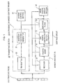
- Fig. 1 is total view of the structure of an ultrasonic enhanced-contrast of a first embodiment mode of the present invention.
- Fig. 2 is a model response spectrum of a contrast medium and of tissue explaining features of the present invention.
- Fig. 3 is a view showing one example of the transmission waveform of an ultrasonic wave in accordance with the first embodiment mode of the present invention.
- Fig. 4 is a view showing one example of the ultrasonic transmission waveform of two irradiations relating to frequency emphasis of the first embodiment mode of the present invention, and the simulation result of frequency spectra of a transmission signal and a response signal obtained by this transmission waveform.
- Fig. 1 is total view of the structure of an ultrasonic enhanced-contrast of a first embodiment mode of the present invention.
- Fig. 2 is a model response spectrum of a contrast medium and of tissue explaining features of the present invention.
- Fig. 3 is a view showing one example of the transmission waveform of an ultrasonic wave in accordance with the first
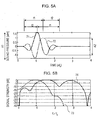
- FIG. 5 is a view showing one example of the ultrasonic transmission waveform of two irradiations relating to frequency and amplitude emphasis of a second embodiment mode of the present invention, and the simulation result of frequency spectra of a transmission signal and a response signal obtained by this transmission waveform.
- Fig. 6 is a view showing another example of the ultrasonic transmission waveform of the two irradiations relating to the frequency and the amplitude emphasis of the second embodiment mode of the present invention, and the simulation result of frequency spectra of the transmission signal and the response signal obtained by this transmission waveform.
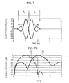
- Fig. 7 is a view showing one example of the transmission waveform of two irradiations in the prior art, and the simulation result of frequency spectra of its transmission signal and an obtained response signal to compare the prior art and the present invention.
- Fig. 1 is a view showing the whole structure of an ultrasonic enhanced-contrast of the first embodiment mode applying the present invention thereto. This embodiment mode is suitable for the execution of first and second features of the present invention.
- an ultrasonic enhanced-contrast 100 comprises an ultrasonic probe 10, a transmitting section 20, a receiving section 30, an image making display section 40 and a system control section 50.
- the transmitting section 20 comprises an arbitrary waveform generator 21 and a transmitter 22.
- the receiving section 30 comprises a receiver 31, a phasing adder 32, a line adding/subtracting unit 33, a band-pass filter 34 and a bypass circuit 35.
- the arbitrary waveform generator 21 of the transmitting section 20 is constructed so as to generate an ultrasonic pulse signal having a single frequency component f 0 .
- the arbitrary waveform generator 21 is constructed so as to generate an ultrasonic signal comprising unit waveforms having different frequency components f1, f2, and having f 0 as their average frequency as in a waveform 51 shown in Fig. 3 .
- the output of the arbitrary waveform generator 21 is supplied to the ultrasonic probe 10 of a wide band type through the transmitter 22.
- the ultrasonic probe 10 is an array type probe, and is constructed by several hundred element vibrators.
- the ultrasonic pulse of the average frequency f 0 is irradiated from the ultrasonic probe 10 to tissue.
- a response signal from a contrast medium distributed in the tissue and a response signal from the tissue itself are received by the ultrasonic probe 10 as a mixed ultrasonic signal.
- the response signal from the contrast medium includes a higher harmonic wave component over a wide frequency band in addition to the component of the fundamental wave f 0 .
- the response signal from the tissue includes the component of the fundamental wave f 0 and the component of a double higher harmonic wave 2f 0 .
- the response signal received by the ultrasonic probe 10 is inputted to the receiver 31.
- the receiver 31 has a preamplifier of a required number of channels corresponding to the number of elements of the ultrasonic probe 10, a TGC amplifier, an A/D converter, etc.
- the receiver 31 amplifies and processes the inputted response signal, and then converts the processed signal to a digital signal, and outputs the digital signal to the phasing adder 32.
- the phasing adder 32 phases and adds a delay difference or a phase difference of the response signals from plural element vibrators relating to one ultrasonic beam.
- the operation of such a phasing adder accomplishes scanning and focus of the ultrasonic beam, but the phasing adder is desirably a so-called digital beam former to minimize the generation of distortion during addition processing. This is because then no unnecessary higher harmonic wave 2f 0 component is generated by the phasing addition processing.
- the response signal phased and added by the phasing adder 32 is supplied to the band-pass filter 34.
- the band width of the band-pass filter 34 can be variably adjusted by the system control section 50 as described later.
- the adjustment of the band-pass width can be realized by using as the band-pass filter 34 a digital filter known as an FIR filter, and varying each coefficient series of this digital FIR filter in accordance with depth or an ultrasonic sound pressure by the system control section 50.
- the digital filter is preferably comprises a third order Chebyshev type filter.
- the response signal having a frequency component selected and extracted in the band-pass filter 34 is directly sent to the image making display section 40 in the realization of the first and second features.
- the image making display section 40 performs processing including normal wave detection, image processing of a normal B-mode image such as compression, Doppler processing such as a color flow, or scanning conversion processing.
- a normal B-mode image such as compression
- Doppler processing such as a color flow
- scanning conversion processing is performed with respect to the contrast medium mode image.
- the above processing operation is executed the number of times required to cover a predetermined section or area of the organic tissue by scanning in the direction of the ultrasonic beam.
- the distribution and the size of the contrast medium is then displayed in a display monitor section (not shown) in the form of image information such as brightness by the processing of the image making display section 40.
- the system control section 50 controls the above series of operations.
- the characteristic operation of the embodiment mode of Fig. 1 constructed in this way will next be explained.
- the picked-up image of the contrast medium mode executed by injecting the contrast medium, e.g., a B-mode fault image is picked up and displayed in the display monitor in advance.
- the contrast mode image obtained in the above operation is overlapped with this B-mode image and is displayed, or only the contrast medium mode image is independently displayed.
- an ultrasonic signal having a single frequency of the fundamental frequency f 0 is generated from the arbitrary waveform generator 21 on the basis of a control signal from the system control section 50, and wave focus processing is performed in the transmitter 22. Thereafter, the processed signal is amplified and supplied to the ultrasonic probe 10, and the ultrasonic beam is transmitted to the organism. A response signal from the organism is detected by the ultrasonic probe 10, and is amplified by the receiver 31, and is converted to a digital signal. Thereafter, the phases (delay times) of the response signals from the same part received by plural vibrators are combined with each other in the phasing adder 32.
- the response signal of a specific frequency component is selected and extracted by the band-pass filter 34.
- the band of the band-pass filter 34 is adjusted to have the fundamental frequency f 0 as its central frequency.
- the image making display section 40 performs wave detection processing of the output of the band-pass filter 34, and also performs image processing such as compression or scanning conversion processing, makes a two-dimensional image (B-mode) of the tissue, and generates this image in the display section (display).
- the scanning and the of the contrast medium mode image in the present invention will next be explained.
- the basic procedure and operation of the scanning and the of the contrast medium mode image are similar to those of the normal B-mode picked-up image.
- a Hanning weighting is applied in the time axis direction, and thus unnecessary response of the contrast medium is avoided.
- amplification and phasing processing are performed by the receiver 31 and the phasing adder 32, as in scanning of tissue.
- the element relating to the first feature of the present invention is the band-pass filter 34 for extracting from the phase-processed response signal the component from the contrast medium.
- the response signal 1 from the contrast medium has high signal strength over a wide frequency band. Therefore, this embodiment mode is characterized in that the band pass width of the band-pass filter 34 is widened in comparison with the prior art, and the response signal from the contrast medium is emphasized with respect to the response signal from the tissue.
- the higher harmonic wave component 2f 0 of the tissue can be neglected in the case of a relatively weak sound pressure and the initial time phase.
- the response signal of the contrast medium can be emphasized over the response signal of the tissue by extracting the response signal over a wide frequency band of 0.8f 0 to 2.5f 0 .
- the higher harmonic wave component 2f 0 from the tissue is strengthened, but the response signal of the contrast medium can be emphasized more than could the prior art even when the response signal is extracted over the frequency band of 0.8f 0 to 2.5f 0 .
- the higher harmonic wave component 2f 0 from the tissue cannot be neglected.
- the band width is set to 0.8f 0 to 1.8f 0 and the higher harmonic wave component 2f 0 of the tissue is removed or attenuated.
- the high frequency component from the contrast medium near 2f 0 is also attenuated, but the amount is slight because the whole response signal of the contrast medium is distributed over a wide frequency band.
- the fundamental wave component of the response signal of the tissue existing near f 0 includes a component caused by a breath and pulsation of the human body and this causes an artifact in the contrast medium image
- it is preferable to slightly narrow the pass band width of the filter to be from 1.2f 0 to 1.8f 0 (or 1.1f 0 to 1.8f 0 ).
- Switching of such a band width is controlled by the system control section 50 based on the set transmitting wave focus or receiving wave focus. For example, since the depth of the response signal corresponds to the time axis of the response signal, the system control section 50 sets the band width to 0.8f 0 to 2.5f 0 in a range in which the time-related position of the response signal inputted to the band-pass filter 34 is shallower than a set depth, and the system control section 50 is switched to 1.2f 0 to 1.8f 0 when focus is in a deep range in real time. For example, a deep location is 4 centimeters when the fundamental frequency f 0 is 2 MHz.
- the two band widths are switched to correspond with two depth areas to make the explanation simple, but the band width may be also continuously narrowed in the depth direction.
- the higher harmonic wave 2f 0 of the tissue and the higher harmonic wave included in the response signal of the contrast medium can be discriminated by adjusting the band width of the band-pass filter 34 in this way.
- the SN ratio (strength ratio of the contrast medium response signal and the tissue response signal) of a enhanced-contrast image can be improved in comparison with the prior art by detecting and extracting the higher harmonic wave component of the response signal from the contrast medium in order to detect and image it.
- the filter for attenuating the higher harmonic wave component 2f 0 may be constructed by using the band-pass filter 34, and also may be constructed by using a band removing filter having a central frequency of 2f 0 by changing the coefficient series of the digital FIR filter constituting the band-pass filter.
- the first feature is that the pass band width of the band-pass filter 34 is widened and varied in accordance with depth of scanning, the time phase and the sound pressure so that extraction of the component of response signal from the contrast medium is emphasized over the response signal from the tissue.
- the second feature of the present invention is that the frequency spectrum of the ultrasonic wave transmitted to the contrast medium is made wide in comparison with the conventional case.
- the ultrasonic signal generated by the arbitrary waveform generator 21 is set to have frequency component units with different respective waveforms, so that plural frequency components make up the entire waveform, a with f 0 as an average of the respective frequency components, as in the waveform 51 shown in Fig. 3 .
- the waveform 51 has unit waveforms in which one sine wave cycle of frequencies f1, f2 is continued.
- a frequency suitable for the tissue and the device, matching the response band of the ultrasonic probe is selected.
- Hanning weighting is applied in the time axis direction, and thus an unnecessary response from the contrast medium is avoided.
- the effects of the present invention are the same even with an ultrasonic signal having a waveform obtained by inverting the polarity of the waveform 51 (rising at the start), and a waveform inverted (f1>f2) with respect to the time axis.
- the response signal of the contrast medium is strengthened over a wide frequency spectrum by transmitting an ultrasonic signal constructed by the connection of unit waveforms having such plural frequency components to the organism. Since the contrast medium has a free resonance frequency distribution corresponding to its particle diameter distribution; more contrast media make a response and the response signal of the contrast medium itself is reinforced by widening the frequency spectrum of the transmitted ultrasonic wave.
- f 0 and 2f 0 are set to be centers of the response signal from the tissue as previously.
- of the difference of frequencies f1, f2, i.e., the distribution width ⁇ f of the waveform unit frequencies is selected within a range of 0.0f 0 to 0.4f 0 .
- the distribution width ⁇ f is preferably set to 0.1f 0 to 0.4f 0 , and is more preferably set to 0.2f 0 to 0.3f 0 .
- the output of the arbitrary waveform generator 21 is not limited to a unit waveform series having the above two frequencies f1, f2, but a waveform having N (N ⁇ 2) frequencies can be used as described later.
- FIG. 1 The total structure of an ultrasonic enhanced-contrast imager of an embodiment mode suitable for the realization of third and fourth features of the present invention is also shown in Fig. 1 .
- this embodiment mode differs from the first embodiment mode in that a line adding/subtracting device 33 is newly arranged between the phasing adder 32 and the band-pass filter 34.
- the ultrasonic signal is transmitted twice at a specific time interval in the same direction as the ultrasonic beam, and an image emphasizing the response signal of the contrast medium is obtained by adding and subtracting the response signals of the first and second ultrasonic signals.
- the arbitrary waveform generator 21 is constructed so as to generate the ultrasonic signal having a first waveform 61 (or 62) as shown in Fig. 4A .
- the first waveform 61 has the same requirements as the waveform explained in Fig. 3 .
- the second waveform 62 is one in which the frequencies f1, f2 of the unit waveforms in the first waveform 61 are assigned in the reverse order.
- the second waveform 62 is asymmetric with respect to polarity inversion as in the prior art.
- the first waveform 61 and the second waveform 62 can be coded for frequency, starting phase and amplitude, and an arbitrary waveform can be generated by connecting the coded one-cycle waveforms.
- the arbitrary waveform generator 21 alternately generates the ultrasonic signals of the first waveform 61 and the second waveform 62 of Fig. 4A as controlled by the system control section 50, at a predetermined time interval in the same ultrasonic beam direction. Each waveform is inputted to the ultrasonic probe 10 through the transmitter 22.
- Such waveforms can be easily made by having the system control section 50 supply digital data obtained by sampling analog signals of the above first waveform 61 and the second waveform 62 to a D/A converter. Further, selection of frequency f1 or f2, the control of the number of the unit waveforms to be connected, and amplitude modulation such as the Hanning weight, etc. are calculated in advance, and are stored in a memory device such as a memory within the system control section (not shown), and are selected and executed by a program every transmission by a computer (not shown) in the system control section 50.
- the ultrasonic signals of the first waveform 61 and the second waveform 62 are transmitted to the organism, two response signals to these ultrasonic signals are inputted to the receiver 31.
- These two response signals are responses to two ultrasonic beams in the same direction, and their times of input are separated from each other by a predetermined time interval.
- the response signals are amplified, A/D-converted and phase information is added in the receiver 31 and the phasing adder 32, and are outputted to the line adding/subtracting device 33 each of these response signals having phase information added to it.
- the line adding/subtracting device 33 makes RF adding and subtracting calculations taking into account the phases of the two response signals, and calculates from the two response signals one response signal (RF line signal) to be displayed.
- the same component (linear component) included in the two response signals is attenuated, and a nonlinear component such as a higher harmonic wave component of the contrast medium, the tissue, etc. is emphasized and inputted to the band-pass filter 34 in the third (or fourth) feature.
- the band-pass filter 34 has a construction similar to that explained in the first embodiment mode, the pass band width varying in accordance with the depth of the response signal source and the time phase of the contrast medium as instructed by the system control section 50, and emphasizes the response signal from a specif ic port ion of the contrast medium.
- the system control section 50 controls a series of operations relating to the arbitrary waveform generator 21, the receiver 31, the phasing adder 32 , the line adding/subtracting device 33 and the band-pass filter 34.
- Fig. 4B shows a frequency spectrum obtained by simulating signals outputted from the line adding/subtracting device 33 when the ultrasonic signal of the first waveform 61 of Fig. 4A is first transmitted and the ultrasonic signal of the secondwaveform 62 of this figure is transmitted second.
- the axis of abscissa of Fig. 4B shows a frequency normalized at the fundamental frequency f 0
- the axis of ordinate shows signal strength normalized at the spectrum peak of a transmitting pulse.
- the broken line 63 in Fig. 4B shows the frequency spectrum of a transmitting ultrasonic wave
- the solid line 64 shows the frequency spectrum of the response signal outputted from the line adding/subtracting device 33.
- the average frequency f 0 of the frequencies is set to be 2 MHz.
- the average frequency f 0 of the frequencies is set to be 2 MHz.
- the coded "frequency f (amplitude A, starting phase ⁇ )" previously mentioned for the first waveform 61 of the first transmission is 1.8 MHz (1.0, 180°) and 2.2 MHz (1.0, 180°).
- the code of the second waveform 62 of the second transmission is 2.2 MHz (1.0, 0°), and 1.8 MHz (1.0, 0°). Further, each of frequency variation ranges ⁇ f, ⁇ f' is 0.4 MHz, and amplitude variation range ⁇ A is 0.0. In each waveform, Hanning weighting is further superposed in the time axis direction.
- Fig. 7A shows an ultrasonic transmission waveform of the conventional system
- Fig. 7B shows frequency spectra of the transmission signal and the response signal.
- the axes of ordinate and abscissa of these Figs. 7A and 7B are the same as the case of Fig. 4 .
- a first waveform 91 is that of the first transmission
- a second waveform 92 is that of the second transmission.
- the response signal near the fundamental frequency f 0 is greatly attenuated in the prior art, and the higher harmonic wave component of the tissue near 2f 0 is emphasized.
- This is suitable for so-called tissue higher harmonic wave image picking-up (called Tissue Harmonic Imaging), but the response signal component of the contrast medium which is widely distributed from f 0 to 2f 0 is reversely attenuated.
- the fundamental frequency f 0 which is a main response signal of the contrast medium is greatly attenuated. Accordingly, in the case of the conventional double irradiating system shown in Fig.
- the output of the line adding/subtracting device 33 has a peak of the spectrum near 1.5 f 0 , and is attenuated near 2f 0 at which the double higher harmonic wave component from the tissue localizes. Accordingly, it can be seen that the spectrum of the response signal from the contrast medium is shifted toward low frequencies in general.
- the spectrum of the response signal from the contrast medium is shifted toward low frequencies, away from the double higher harmonic wave component included in the response signal from the organic tissue which is an obstacle to imaging of the contrast medium, so that only the contrast medium-generated signal can be emphasized and extracted by the control of various kinds of band-pass filters described later.
- the discrimination ratio of the contrast medium response signal and the higher harmonic wave of the tissue response signal is taken to be the energy ratio (area ratio) of the spectrum in the band ranging from 1.2f 0 to 1.8f 0 and the spectrum in the band ranging from 1.8f 0 to 2.2f 0 , an improvement is made approximately by 10 dB to 20 dB in comparison with the prior art ( Fig. 7 ).
- the pass band width of the band-pass filter 34 is the same as that described in the explanation relating to the second feature. Namely, a signal obtained by the line adding/subtracting device 32 includes the response signal from the contrast medium over a wide band from 0.8f 0 to 2.5f 0 in the imaging of a shallow location. Accordingly, this obtained signal can be taken to be a signal from the contrast medium and imaged as it is.
- the effect of the change in the band in this case is the attenuation of the frequency component near 2f 0 . Accordingly, this attenuation can be executed instead by the addition of a band removing filter with 2f 0 as a central frequency, or by the removing filter itself.
- the response signal of the contrast medium can be emphasized more in the imaging in comparison with the second feature of the first embodiment mode.
- each waveform of one cycle making up the transmission waveform of the ultrasonic wave is coded by the frequency f, the amplitude A and the starting phase ⁇ , and their waveforms are connected.
- the frequency distribution of the transmitting signal of the ultrasonic wave twice irradiated is biased by setting the frequencies of the first cycle of the first waveform 61 and the second waveform 62 to be different as in the waveform shown in Fig. 4A .
- the fourth feature of the present invention in the second embodiment mode can be realized by using the ultrasonic enhanced-contrast shown in Fig. 1 .
- This embodiment differs from the above third feature in that the arbitrary waveform generator 21 is constructed so as to generate an ultrasonic signal in the first waveform 71 and the second waveform 72 shown in Fig. 5A and the first waveform 81 and the second waveform 82 shown in Fig. 6 .
- the other parts are similar to those in the ultrasonic enhanced-contrast shown in Fig. 1 . Accordingly, the different points will be explained chiefly.
- Figs. 5A and 6A differ from Fig. 4A in that the amplitudes of the unit waveform of the first cycle of the first waveform and the second waveform are set to be greater than the amplitude of subsequent unit waveforms.
- Figs. 5B and 6B show simulation results similar to those of Fig. 4B .
- Broken lines 73, 83 show frequency spectra of the transmitted ultrasonic wave
- solid lines 74, 84 show frequency spectra of the response signal of the contrast medium with lines added and subtracted.
- the codes f (A, ⁇ ) of the first waveform 71 of Fig. 5A are, in order, 1.7 MHz (1.1, 180°) and 2.3 MHz (0.8, 0°), and the codes f (A, theta) of the second waveform 72 are, in order, 2.3MHz (1.1, 0°) and 1.7 MHz (0.8, 180°).
- Their average frequency is 2 MHz.
- the frequency changing width ⁇ f is set to 0.6 MHz as opposed to 0.4 MHz of Fig. 4
- the amplitude changing width ⁇ A is set to 0.3 as opposed to 0.0 of Fig. 4 .
- the spectrum of the response signal from the contrast medium obtained by adding the response signals corresponding to the two ultrasonic transmissions is shifted toward the fundamental wave f 0 , and has a peak near 1.5f 0 as can be seen from Fig. 5B in this case.
- the attenuating effect with respect to the higher harmonic wave component 2f 0 included in the response signal from the tissue is slightly inferior, but the distribution of the response signal from the contrast medium obtained by the addition can be emphasized over the higher harmonic wave from the tissue by extraction with the band-pass filter set to 1.2f 0 to 1.8f 0 .
- the band-pass filter is further widened (0.8f 0 to 1.8f 0 ) in frequency and the energy ratio of higher harmonic waves from the contrast medium with the higher harmonic wave from tissue is high so that the discrimination ratio can be improved.
- the codes f (A, ⁇ ) of the first waveform 81 of Fig. 6A are, in order, 1.8 MHz (1.0, 180°) and 2.2 MHz (0.9, 0°), and the codes f (A, ⁇ ) of the second waveform 82 are, in order, 2.2 MHz (1.0, 0°) and 1.8 MHz (0.9, 180°).
- Their average frequency is 2 MHz.
- the frequency variation range ⁇ f is 0.4 MHz, the same as Fig. 4
- the amplitude variation range ⁇ A is set to be 0.1 in contrast to 0.0 of Fig. 4 .
- the spectrum of the response signal from the contrast medium obtained by adding the response signals corresponding to the two ultrasonic transmissions is also shifted toward the fundamental wave f 0 , and has a peak near 1.5f 0 as can be seen from Fig. 6B in this case.
- the attenuating effect with respect to the higher harmonic wave component 2f 0 included in the response signal from the tissue is 15 dB in comparison with about 5 dB of Fig. 4B and is therefore improved.
- the frequency component corresponding to the triple-frequency harmonic wave in the response of the contrast medium is shifted to 2.5f 0 so that it is suitable for a case in which the fifth feature for extracting a frequency band almost having no higher harmonic wave from the tissue is executed.
- the corresponding spectrum peak is near 3f 0 , and it should be emphasized that this peak lies outside the frequency response range in the ultrasonic probe having a normal ratio band as mentioned above.
- the device is formed so that the codes f (A, ⁇ ) of the first waveform are, in order, 1.8 MHz (1.1, 180°) and 2.2 MHz (0.9, 0°), and the codes f (A, ⁇ ) of the second waveform are, in order, 2.0 MHz (1.1, 0°) and 2.0 MHz (1.0, 180°) and the codes f (A, ⁇ ) of a third waveform are, in order, 2.2 MHz (1.1, 180°) and 1.8 MHz (1.0, 0°). Their average frequency is set to 2 MHz.
- the ultrasonic beam is irradiated in the same direction in the two signal transmissions.
- the contrast medium is trapped to the tissue as in the latter period time phase, the movement of the contrast medium is slight. Accordingly, no effects of the present invention are changed even when the direction of the two ultrasonic beams are slightly different.
Landscapes
- Engineering & Computer Science (AREA)
- Health & Medical Sciences (AREA)
- Physics & Mathematics (AREA)
- Life Sciences & Earth Sciences (AREA)
- Remote Sensing (AREA)
- Radar, Positioning & Navigation (AREA)
- Surgery (AREA)
- Public Health (AREA)
- Biomedical Technology (AREA)
- Heart & Thoracic Surgery (AREA)
- Medical Informatics (AREA)
- Molecular Biology (AREA)
- Pathology (AREA)
- Animal Behavior & Ethology (AREA)
- General Health & Medical Sciences (AREA)
- Radiology & Medical Imaging (AREA)
- Veterinary Medicine (AREA)
- Acoustics & Sound (AREA)
- Computer Networks & Wireless Communication (AREA)
- General Physics & Mathematics (AREA)
- Nuclear Medicine, Radiotherapy & Molecular Imaging (AREA)
- Biophysics (AREA)
- Hematology (AREA)
- Nonlinear Science (AREA)
- Ultra Sonic Daignosis Equipment (AREA)
Applications Claiming Priority (3)
| Application Number | Priority Date | Filing Date | Title |
|---|---|---|---|
| JP2001025783A JP4232134B2 (ja) | 2001-02-01 | 2001-02-01 | 超音波造影描画装置 |
| JP2001025778A JP4269131B2 (ja) | 2001-02-01 | 2001-02-01 | 超音波造影描画装置 |
| EP02710465A EP1358849B1 (fr) | 2001-02-01 | 2002-02-01 | Dispositif ultrasonore de formation d'images avec contraste ameliore |
Related Parent Applications (1)
| Application Number | Title | Priority Date | Filing Date |
|---|---|---|---|
| EP02710465.2 Division | 2002-02-01 |
Publications (2)
| Publication Number | Publication Date |
|---|---|
| EP2305121A1 true EP2305121A1 (fr) | 2011-04-06 |
| EP2305121B1 EP2305121B1 (fr) | 2012-05-09 |
Family
ID=26608793
Family Applications (2)
| Application Number | Title | Priority Date | Filing Date |
|---|---|---|---|
| EP02710465A Expired - Lifetime EP1358849B1 (fr) | 2001-02-01 | 2002-02-01 | Dispositif ultrasonore de formation d'images avec contraste ameliore |
| EP10008191A Expired - Lifetime EP2305121B1 (fr) | 2001-02-01 | 2002-02-01 | Dispositif d'imagerie ultrasonore à contraste amélioré |
Family Applications Before (1)
| Application Number | Title | Priority Date | Filing Date |
|---|---|---|---|
| EP02710465A Expired - Lifetime EP1358849B1 (fr) | 2001-02-01 | 2002-02-01 | Dispositif ultrasonore de formation d'images avec contraste ameliore |
Country Status (4)
| Country | Link |
|---|---|
| US (2) | US7198601B2 (fr) |
| EP (2) | EP1358849B1 (fr) |
| DE (1) | DE60239785D1 (fr) |
| WO (1) | WO2002060326A1 (fr) |
Families Citing this family (24)
| Publication number | Priority date | Publication date | Assignee | Title |
|---|---|---|---|---|
| JP4192490B2 (ja) * | 2002-04-26 | 2008-12-10 | 株式会社日立メディコ | 超音波診断装置 |
| US8038616B2 (en) | 2003-05-30 | 2011-10-18 | Surf Technology As | Acoustic imaging by nonlinear low frequency manipulation of high frequency scattering and propagation properties |
| US20040267129A1 (en) * | 2003-05-30 | 2004-12-30 | Angelsen Bjorn A.J. | Ultrasonic contrast agent detection and imaging by low frequency manipulation of high frequency scattering properties |
| US7361180B2 (en) | 2004-05-07 | 2008-04-22 | Usgi Medical, Inc. | Apparatus for manipulating and securing tissue |
| JP4602993B2 (ja) * | 2004-01-16 | 2010-12-22 | ボストン サイエンティフィック リミテッド | 医用撮像のための方法及び装置 |
| ITPI20040066A1 (it) * | 2004-09-21 | 2004-12-21 | Cnr Consiglio Naz Delle Ricerche | Metodo e dispositivo per la valutazione automatica di indici di funzionalita' cardiovascolare mediante elaborazione di immagini ecografiche |
| US7967754B2 (en) * | 2004-10-14 | 2011-06-28 | Scimed Life Systems, Inc. | Integrated bias circuitry for ultrasound imaging devices configured to image the interior of a living being |
| EP1803402A4 (fr) * | 2004-10-20 | 2008-10-29 | Toshiba Kk | Équipement de diagnostic à ultrasons et méthode de commande pour celui-ci |
| WO2006094951A1 (fr) * | 2005-03-03 | 2006-09-14 | Bracco Research Sa | Système d’imagerie médicale fondé sur un agent de contraste ciblé |
| EP1884195A4 (fr) * | 2005-05-27 | 2011-03-30 | Hitachi Medical Corp | Ultrasonographe et procédé d'affichage d'image ultrasonique |
| US7389692B2 (en) * | 2005-11-04 | 2008-06-24 | Ge Inspection Technologies, Lp | Digital log amplifier for ultrasonic testing |
| US20070167798A1 (en) * | 2005-11-23 | 2007-07-19 | Cai Anming H | Contrast agent augmented ultrasound therapy system with ultrasound imaging guidance for thrombus treatment |
| WO2007113758A2 (fr) * | 2006-03-31 | 2007-10-11 | Koninklijke Philips Electronics, N.V. | Méthode et appareil pour la détermination de niveaux d'hydratation |
| JP5154554B2 (ja) * | 2006-08-01 | 2013-02-27 | ボストン サイエンティフィック サイムド,インコーポレイテッド | 非線形イメージングのためのパルスインバージョンシーケンス |
| US20080125657A1 (en) * | 2006-09-27 | 2008-05-29 | Chomas James E | Automated contrast agent augmented ultrasound therapy for thrombus treatment |
| JP5162923B2 (ja) * | 2007-02-27 | 2013-03-13 | 株式会社日立製作所 | 超音波撮像装置 |
| JP5307453B2 (ja) * | 2008-05-29 | 2013-10-02 | 株式会社日立メディコ | 超音波診断装置 |
| US8254650B2 (en) * | 2009-02-27 | 2012-08-28 | General Electric Company | System and method for contrast enhancement of time-resolved fluorescence images |
| JP5441781B2 (ja) * | 2010-03-25 | 2014-03-12 | キヤノン株式会社 | 光音響イメージング装置、光音響イメージング方法及びプログラム |
| JP5632680B2 (ja) * | 2010-08-25 | 2014-11-26 | 日立アロカメディカル株式会社 | 超音波画像処理装置 |
| JP5924296B2 (ja) * | 2013-03-19 | 2016-05-25 | コニカミノルタ株式会社 | 超音波画像診断装置 |
| US10888707B2 (en) * | 2013-03-19 | 2021-01-12 | Genovus Biotechnologies Inc. | Muscle optimization device and method |
| JP6237007B2 (ja) * | 2013-09-02 | 2017-11-29 | セイコーエプソン株式会社 | 超音波測定装置、超音波画像装置及び超音波測定方法 |
| JP6978316B2 (ja) * | 2015-01-29 | 2021-12-08 | コーニンクレッカ フィリップス エヌ ヴェKoninklijke Philips N.V. | ブロードバンドの混合された基本波及び高調波周波数超音波診断イメージング |
Citations (8)
| Publication number | Priority date | Publication date | Assignee | Title |
|---|---|---|---|---|
| EP0770352A1 (fr) * | 1995-10-10 | 1997-05-02 | Advanced Technology Laboratories, Inc. | Imagerie diagnostique à ultrasons utilisant des agents de contraste |
| US5632277A (en) | 1996-06-28 | 1997-05-27 | Siemens Medical Systems, Inc. | Ultrasound imaging system employing phase inversion subtraction to enhance the image |
| US5706819A (en) | 1995-10-10 | 1998-01-13 | Advanced Technology Laboratories, Inc. | Ultrasonic diagnostic imaging with harmonic contrast agents |
| EP0913704A2 (fr) * | 1997-10-02 | 1999-05-06 | Sunnybrook Health Science Centre | Système d'imagerie ultrasonique à Doppler pour le diagnostic à inversion d'impulsions |
| EP0916967A2 (fr) * | 1997-11-17 | 1999-05-19 | ATL Ultrasound, Inc. | Impulsions d'émission pour l'imagerie non-lineaire à ultrasons |
| JPH11137547A (ja) * | 1997-11-11 | 1999-05-25 | Ge Yokogawa Medical Systems Ltd | 超音波撮像方法および装置 |
| JP2000300554A (ja) | 1999-04-26 | 2000-10-31 | Ge Yokogawa Medical Systems Ltd | 超音波診断装置 |
| US6168565B1 (en) * | 1999-03-31 | 2001-01-02 | Acuson Corporation | Medical diagnostic ultrasound system and method for simultaneous phase correction of two frequency band signal components |
Family Cites Families (21)
| Publication number | Priority date | Publication date | Assignee | Title |
|---|---|---|---|---|
| US5749364A (en) * | 1996-06-21 | 1998-05-12 | Acuson Corporation | Method and apparatus for mapping pressure and tissue properties |
| JPH1028685A (ja) * | 1996-07-18 | 1998-02-03 | Ge Yokogawa Medical Syst Ltd | 超音波イメージング方法及び装置並びに超音波造影剤及びその製造方法 |
| JP3519882B2 (ja) * | 1996-09-13 | 2004-04-19 | ジーイー横河メディカルシステム株式会社 | 超音波撮像装置 |
| US5879303A (en) * | 1996-09-27 | 1999-03-09 | Atl Ultrasound | Ultrasonic diagnostic imaging of response frequency differing from transmit frequency |
| US6458083B1 (en) * | 1996-11-26 | 2002-10-01 | Koninklijke Philips Electronics N.V. | Ultrasonic harmonic imaging with adaptive image formation |
| JP3908348B2 (ja) * | 1997-09-11 | 2007-04-25 | 株式会社東芝 | 超音波診断装置 |
| JP3984698B2 (ja) * | 1998-03-12 | 2007-10-03 | ジーイー横河メディカルシステム株式会社 | 超音波撮像装置 |
| JP4130004B2 (ja) * | 1998-03-13 | 2008-08-06 | ジーイー横河メディカルシステム株式会社 | 超音波撮像装置 |
| JP4116143B2 (ja) * | 1998-04-10 | 2008-07-09 | 株式会社東芝 | 超音波診断装置 |
| US6102858A (en) * | 1998-04-23 | 2000-08-15 | General Electric Company | Method and apparatus for three-dimensional ultrasound imaging using contrast agents and harmonic echoes |
| US6132377A (en) * | 1999-03-31 | 2000-10-17 | Acuson Corporation | Medical diagnostic ultrasonic imaging system and method using differential sub-band detection techniques |
| US6290647B1 (en) * | 1999-07-02 | 2001-09-18 | Acuson Corporation | Contrast agent imaging with subharmonic and harmonic signals in diagnostic medical ultrasound |
| US6461303B2 (en) * | 2000-01-19 | 2002-10-08 | Bjorn Angelsen | Method of detecting ultrasound contrast agent in soft tissue, and quantitating blood perfusion through regions of tissue |
| US6413221B1 (en) * | 2000-02-11 | 2002-07-02 | George A Brock-Fisher | Ultrasonic system and method employing variable filtering of echo return signals |
| US6508767B2 (en) * | 2000-02-16 | 2003-01-21 | Koninklijke Philips Electronics N.V. | Ultrasonic harmonic image segmentation |
| US6516667B1 (en) * | 2000-03-07 | 2003-02-11 | Koninklijke Philips Electronics N.V. | Ultrasonic harmonic signal acquisition |
| US6497666B1 (en) * | 2000-10-25 | 2002-12-24 | Acuson Corporation | Medical ultrasonic contrast agent imaging method and apparatus |
| JP4712980B2 (ja) * | 2001-01-18 | 2011-06-29 | 株式会社日立メディコ | 超音波装置 |
| US6514206B2 (en) * | 2001-03-09 | 2003-02-04 | Koninklijke Philips Electronics, N.V. | Simultaneous fundamental and harmonic ultrasonic imaging |
| US6626836B2 (en) * | 2001-04-04 | 2003-09-30 | Siemens Medical Solutions Usa, Inc. | Adaptive signal processing scheme for contrast agent imaging |
| US6656123B2 (en) * | 2001-12-19 | 2003-12-02 | Koninklijke Philips Electronics N.V. | Combined fundamental and harmonic ultrasonic imaging at low MI or deeper depths |
-
2002
- 2002-02-01 EP EP02710465A patent/EP1358849B1/fr not_active Expired - Lifetime
- 2002-02-01 EP EP10008191A patent/EP2305121B1/fr not_active Expired - Lifetime
- 2002-02-01 DE DE60239785T patent/DE60239785D1/de not_active Expired - Lifetime
- 2002-02-01 US US10/392,612 patent/US7198601B2/en not_active Expired - Lifetime
- 2002-02-01 WO PCT/JP2002/000839 patent/WO2002060326A1/fr not_active Ceased
-
2007
- 2007-03-22 US US11/723,801 patent/US7850612B2/en not_active Expired - Lifetime
Patent Citations (8)
| Publication number | Priority date | Publication date | Assignee | Title |
|---|---|---|---|---|
| EP0770352A1 (fr) * | 1995-10-10 | 1997-05-02 | Advanced Technology Laboratories, Inc. | Imagerie diagnostique à ultrasons utilisant des agents de contraste |
| US5706819A (en) | 1995-10-10 | 1998-01-13 | Advanced Technology Laboratories, Inc. | Ultrasonic diagnostic imaging with harmonic contrast agents |
| US5632277A (en) | 1996-06-28 | 1997-05-27 | Siemens Medical Systems, Inc. | Ultrasound imaging system employing phase inversion subtraction to enhance the image |
| EP0913704A2 (fr) * | 1997-10-02 | 1999-05-06 | Sunnybrook Health Science Centre | Système d'imagerie ultrasonique à Doppler pour le diagnostic à inversion d'impulsions |
| JPH11137547A (ja) * | 1997-11-11 | 1999-05-25 | Ge Yokogawa Medical Systems Ltd | 超音波撮像方法および装置 |
| EP0916967A2 (fr) * | 1997-11-17 | 1999-05-19 | ATL Ultrasound, Inc. | Impulsions d'émission pour l'imagerie non-lineaire à ultrasons |
| US6168565B1 (en) * | 1999-03-31 | 2001-01-02 | Acuson Corporation | Medical diagnostic ultrasound system and method for simultaneous phase correction of two frequency band signal components |
| JP2000300554A (ja) | 1999-04-26 | 2000-10-31 | Ge Yokogawa Medical Systems Ltd | 超音波診断装置 |
Non-Patent Citations (1)
| Title |
|---|
| PETER J. A. FRINKING ET AL.: "Ultrasound Contrast Imaging: Current and New Potential Methods", ULTRASOUND IN MEDICINE & BIOLOGY, vol. 26, no. 6, 2000, pages 965 |
Also Published As
| Publication number | Publication date |
|---|---|
| US20040059218A1 (en) | 2004-03-25 |
| US20070173723A1 (en) | 2007-07-26 |
| EP2305121B1 (fr) | 2012-05-09 |
| EP1358849B1 (fr) | 2011-04-20 |
| EP1358849A1 (fr) | 2003-11-05 |
| US7850612B2 (en) | 2010-12-14 |
| DE60239785D1 (de) | 2011-06-01 |
| EP1358849A4 (fr) | 2006-04-05 |
| WO2002060326A1 (fr) | 2002-08-08 |
| US7198601B2 (en) | 2007-04-03 |
Similar Documents
| Publication | Publication Date | Title |
|---|---|---|
| US7850612B2 (en) | Ultrasonic enhanced-contrast imager and method | |
| EP0730433B1 (fr) | Imagerie ultrasonique par contraste spectral | |
| US6929609B2 (en) | Ultrasonic diagnosing/treating device and method therefor | |
| US8043220B2 (en) | Ultrasonograph | |
| EP0770352B1 (fr) | Imagerie diagnostique à ultrasons utilisant des agents de contraste | |
| CN104013419B (zh) | 医疗超声波中的自适应声压估计 | |
| EP2578162B1 (fr) | Dispositif de diagnostic à ultrasons | |
| US20050256404A1 (en) | Ultrasonic diagnostic apparatus and ultrasonic diagnostic method | |
| MXPA96001754A (en) | Images by spectro ultrason contrast | |
| KR20050058365A (ko) | 개선된 고조파 영상 처리를 위한 시스템 및 방법 | |
| JP4642977B2 (ja) | 超音波診断装置及び超音波イメージング方法 | |
| EP1428474B1 (fr) | Appareil d'imagerie ultrasonore et méthode d'utilisation | |
| US6726630B2 (en) | Ultrasound diagnosis apparatus for imaging with a contrast agent | |
| JP4232134B2 (ja) | 超音波造影描画装置 | |
| JP4370482B2 (ja) | 超音波造影描画装置 | |
| JP4728466B2 (ja) | 物質をイメージングする方法及びイメージング・システム | |
| JP4317996B2 (ja) | 超音波造影描画装置 | |
| US12433568B2 (en) | Ultrasonic image processing device | |
| JP4269131B2 (ja) | 超音波造影描画装置 | |
| CN113117268B (zh) | 用于检测空化效应的装置及超声治疗设备 | |
| CN113117261B (zh) | 用于检测空化效应的装置及超声治疗设备 | |
| Park | High frequency chirp coded excitation ultrasound imaging system |
Legal Events
| Date | Code | Title | Description |
|---|---|---|---|
| PUAI | Public reference made under article 153(3) epc to a published international application that has entered the european phase |
Free format text: ORIGINAL CODE: 0009012 |
|
| AC | Divisional application: reference to earlier application |
Ref document number: 1358849 Country of ref document: EP Kind code of ref document: P |
|
| AK | Designated contracting states |
Kind code of ref document: A1 Designated state(s): DE FR GB IT NL |
|
| GRAP | Despatch of communication of intention to grant a patent |
Free format text: ORIGINAL CODE: EPIDOSNIGR1 |
|
| 17P | Request for examination filed |
Effective date: 20111006 |
|
| RIC1 | Information provided on ipc code assigned before grant |
Ipc: A61B 8/00 20060101AFI20111026BHEP Ipc: G01S 7/52 20060101ALI20111026BHEP |
|
| GRAS | Grant fee paid |
Free format text: ORIGINAL CODE: EPIDOSNIGR3 |
|
| GRAA | (expected) grant |
Free format text: ORIGINAL CODE: 0009210 |
|
| AC | Divisional application: reference to earlier application |
Ref document number: 1358849 Country of ref document: EP Kind code of ref document: P |
|
| AK | Designated contracting states |
Kind code of ref document: B1 Designated state(s): DE FR GB IT NL |
|
| REG | Reference to a national code |
Ref country code: GB Ref legal event code: FG4D |
|
| REG | Reference to a national code |
Ref country code: DE Ref legal event code: R096 Ref document number: 60242918 Country of ref document: DE Effective date: 20120712 |
|
| REG | Reference to a national code |
Ref country code: NL Ref legal event code: T3 |
|
| PLBE | No opposition filed within time limit |
Free format text: ORIGINAL CODE: 0009261 |
|
| STAA | Information on the status of an ep patent application or granted ep patent |
Free format text: STATUS: NO OPPOSITION FILED WITHIN TIME LIMIT |
|
| 26N | No opposition filed |
Effective date: 20130212 |
|
| REG | Reference to a national code |
Ref country code: DE Ref legal event code: R097 Ref document number: 60242918 Country of ref document: DE Effective date: 20130212 |
|
| REG | Reference to a national code |
Ref country code: FR Ref legal event code: PLFP Year of fee payment: 15 |
|
| REG | Reference to a national code |
Ref country code: DE Ref legal event code: R082 Ref document number: 60242918 Country of ref document: DE Representative=s name: STREHL SCHUEBEL-HOPF & PARTNER MBB PATENTANWAE, DE Ref country code: DE Ref legal event code: R081 Ref document number: 60242918 Country of ref document: DE Owner name: HITACHI, LTD., JP Free format text: FORMER OWNER: HITACHI MEDICAL CORP., TOKIO/TOKYO, JP |
|
| REG | Reference to a national code |
Ref country code: NL Ref legal event code: PD Owner name: HITACHI, LTD.; JP Free format text: DETAILS ASSIGNMENT: CHANGE OF OWNER(S), ASSIGNMENT; FORMER OWNER NAME: HITACHI MEDICAL CORPORATION Effective date: 20161222 |
|
| REG | Reference to a national code |
Ref country code: FR Ref legal event code: PLFP Year of fee payment: 16 |
|
| PGFP | Annual fee paid to national office [announced via postgrant information from national office to epo] |
Ref country code: DE Payment date: 20170227 Year of fee payment: 16 Ref country code: FR Payment date: 20170118 Year of fee payment: 16 |
|
| PGFP | Annual fee paid to national office [announced via postgrant information from national office to epo] |
Ref country code: NL Payment date: 20170209 Year of fee payment: 16 Ref country code: GB Payment date: 20170126 Year of fee payment: 16 |
|
| REG | Reference to a national code |
Ref country code: GB Ref legal event code: 732E Free format text: REGISTERED BETWEEN 20170504 AND 20170510 |
|
| PGFP | Annual fee paid to national office [announced via postgrant information from national office to epo] |
Ref country code: IT Payment date: 20170214 Year of fee payment: 16 |
|
| REG | Reference to a national code |
Ref country code: FR Ref legal event code: CA Effective date: 20170802 Ref country code: FR Ref legal event code: TP Owner name: HITACHI, LTD., JP Effective date: 20170802 |
|
| REG | Reference to a national code |
Ref country code: DE Ref legal event code: R119 Ref document number: 60242918 Country of ref document: DE |
|
| REG | Reference to a national code |
Ref country code: NL Ref legal event code: MM Effective date: 20180301 |
|
| GBPC | Gb: european patent ceased through non-payment of renewal fee |
Effective date: 20180201 |
|
| REG | Reference to a national code |
Ref country code: FR Ref legal event code: ST Effective date: 20181031 |
|
| PG25 | Lapsed in a contracting state [announced via postgrant information from national office to epo] |
Ref country code: NL Free format text: LAPSE BECAUSE OF NON-PAYMENT OF DUE FEES Effective date: 20180301 |
|
| PG25 | Lapsed in a contracting state [announced via postgrant information from national office to epo] |
Ref country code: DE Free format text: LAPSE BECAUSE OF NON-PAYMENT OF DUE FEES Effective date: 20180901 |
|
| PG25 | Lapsed in a contracting state [announced via postgrant information from national office to epo] |
Ref country code: IT Free format text: LAPSE BECAUSE OF NON-PAYMENT OF DUE FEES Effective date: 20180201 Ref country code: GB Free format text: LAPSE BECAUSE OF NON-PAYMENT OF DUE FEES Effective date: 20180201 Ref country code: FR Free format text: LAPSE BECAUSE OF NON-PAYMENT OF DUE FEES Effective date: 20180228 |