EP2305366A1 - Verfahren zum Abscheiden von CO2 mittels CaO und der exothermen Reduktion eines Feststoffs - Google Patents
Verfahren zum Abscheiden von CO2 mittels CaO und der exothermen Reduktion eines Feststoffs Download PDFInfo
- Publication number
- EP2305366A1 EP2305366A1 EP09382169A EP09382169A EP2305366A1 EP 2305366 A1 EP2305366 A1 EP 2305366A1 EP 09382169 A EP09382169 A EP 09382169A EP 09382169 A EP09382169 A EP 09382169A EP 2305366 A1 EP2305366 A1 EP 2305366A1
- Authority
- EP
- European Patent Office
- Prior art keywords
- solid
- gas
- stream
- reactor
- caco
- Prior art date
- Legal status (The legal status is an assumption and is not a legal conclusion. Google has not performed a legal analysis and makes no representation as to the accuracy of the status listed.)
- Granted
Links
- 238000000034 method Methods 0.000 title claims abstract description 178
- 239000007787 solid Substances 0.000 title claims abstract description 103
- 230000009467 reduction Effects 0.000 title claims description 46
- VTYYLEPIZMXCLO-UHFFFAOYSA-L Calcium carbonate Chemical group [Ca+2].[O-]C([O-])=O VTYYLEPIZMXCLO-UHFFFAOYSA-L 0.000 claims abstract description 218
- 229910000019 calcium carbonate Inorganic materials 0.000 claims abstract description 109
- 238000006722 reduction reaction Methods 0.000 claims abstract description 64
- 230000008569 process Effects 0.000 claims abstract description 48
- 239000000446 fuel Substances 0.000 claims abstract description 47
- 238000002485 combustion reaction Methods 0.000 claims abstract description 42
- 238000000354 decomposition reaction Methods 0.000 claims abstract description 32
- 238000002407 reforming Methods 0.000 claims abstract description 32
- 125000004122 cyclic group Chemical group 0.000 claims abstract description 10
- 239000007789 gas Substances 0.000 claims description 136
- VNWKTOKETHGBQD-UHFFFAOYSA-N methane Chemical compound C VNWKTOKETHGBQD-UHFFFAOYSA-N 0.000 claims description 66
- 238000007254 oxidation reaction Methods 0.000 claims description 60
- 230000003647 oxidation Effects 0.000 claims description 52
- 238000001354 calcination Methods 0.000 claims description 45
- 239000000203 mixture Substances 0.000 claims description 34
- 239000002737 fuel gas Substances 0.000 claims description 32
- 238000002309 gasification Methods 0.000 claims description 27
- 239000003345 natural gas Substances 0.000 claims description 21
- 230000015572 biosynthetic process Effects 0.000 claims description 19
- 229910052751 metal Inorganic materials 0.000 claims description 18
- 239000002184 metal Substances 0.000 claims description 18
- 238000003786 synthesis reaction Methods 0.000 claims description 18
- 239000004449 solid propellant Substances 0.000 claims description 16
- 229910052925 anhydrite Inorganic materials 0.000 claims description 15
- OSGAYBCDTDRGGQ-UHFFFAOYSA-L calcium sulfate Chemical group [Ca+2].[O-]S([O-])(=O)=O OSGAYBCDTDRGGQ-UHFFFAOYSA-L 0.000 claims description 13
- 239000002028 Biomass Substances 0.000 claims description 9
- QAOWNCQODCNURD-UHFFFAOYSA-L Sulfate Chemical compound [O-]S([O-])(=O)=O QAOWNCQODCNURD-UHFFFAOYSA-L 0.000 claims description 2
- UCKMPCXJQFINFW-UHFFFAOYSA-N Sulphide Chemical compound [S-2] UCKMPCXJQFINFW-UHFFFAOYSA-N 0.000 claims description 2
- 229930195733 hydrocarbon Natural products 0.000 abstract description 7
- 150000002430 hydrocarbons Chemical class 0.000 abstract description 7
- 239000004215 Carbon black (E152) Substances 0.000 abstract description 2
- 230000008030 elimination Effects 0.000 abstract 1
- 238000003379 elimination reaction Methods 0.000 abstract 1
- 238000006243 chemical reaction Methods 0.000 description 96
- 239000010949 copper Substances 0.000 description 87
- QPLDLSVMHZLSFG-UHFFFAOYSA-N Copper oxide Chemical compound [Cu]=O QPLDLSVMHZLSFG-UHFFFAOYSA-N 0.000 description 83
- 239000002594 sorbent Substances 0.000 description 20
- 230000008901 benefit Effects 0.000 description 19
- 229910052799 carbon Inorganic materials 0.000 description 16
- 239000001257 hydrogen Substances 0.000 description 16
- 229910052739 hydrogen Inorganic materials 0.000 description 16
- 239000000463 material Substances 0.000 description 16
- 238000013461 design Methods 0.000 description 15
- UFHFLCQGNIYNRP-UHFFFAOYSA-N Hydrogen Chemical compound [H][H] UFHFLCQGNIYNRP-UHFFFAOYSA-N 0.000 description 14
- 239000000567 combustion gas Substances 0.000 description 14
- 230000008929 regeneration Effects 0.000 description 14
- 238000011069 regeneration method Methods 0.000 description 14
- 238000004519 manufacturing process Methods 0.000 description 13
- 239000000047 product Substances 0.000 description 13
- 238000000926 separation method Methods 0.000 description 12
- 238000010521 absorption reaction Methods 0.000 description 11
- 230000005611 electricity Effects 0.000 description 9
- 229910044991 metal oxide Inorganic materials 0.000 description 9
- 150000004706 metal oxides Chemical class 0.000 description 9
- 238000011084 recovery Methods 0.000 description 9
- 230000002441 reversible effect Effects 0.000 description 9
- OKTJSMMVPCPJKN-UHFFFAOYSA-N Carbon Chemical compound [C] OKTJSMMVPCPJKN-UHFFFAOYSA-N 0.000 description 8
- PNEYBMLMFCGWSK-UHFFFAOYSA-N aluminium oxide Inorganic materials [O-2].[O-2].[O-2].[Al+3].[Al+3] PNEYBMLMFCGWSK-UHFFFAOYSA-N 0.000 description 8
- 229910052593 corundum Inorganic materials 0.000 description 8
- 238000006057 reforming reaction Methods 0.000 description 8
- 229910001845 yogo sapphire Inorganic materials 0.000 description 8
- 239000011575 calcium Substances 0.000 description 7
- 238000005516 engineering process Methods 0.000 description 7
- 230000010354 integration Effects 0.000 description 7
- XEEYBQQBJWHFJM-UHFFFAOYSA-N iron Substances [Fe] XEEYBQQBJWHFJM-UHFFFAOYSA-N 0.000 description 7
- UQSXHKLRYXJYBZ-UHFFFAOYSA-N iron oxide Inorganic materials [Fe]=O UQSXHKLRYXJYBZ-UHFFFAOYSA-N 0.000 description 7
- PXHVJJICTQNCMI-UHFFFAOYSA-N nickel Substances [Ni] PXHVJJICTQNCMI-UHFFFAOYSA-N 0.000 description 7
- 239000000126 substance Substances 0.000 description 7
- 239000003054 catalyst Substances 0.000 description 6
- 239000003153 chemical reaction reagent Substances 0.000 description 6
- 239000003245 coal Substances 0.000 description 6
- 238000003860 storage Methods 0.000 description 6
- QVGXLLKOCUKJST-UHFFFAOYSA-N atomic oxygen Chemical compound [O] QVGXLLKOCUKJST-UHFFFAOYSA-N 0.000 description 5
- JEIPFZHSYJVQDO-UHFFFAOYSA-N iron(III) oxide Inorganic materials O=[Fe]O[Fe]=O JEIPFZHSYJVQDO-UHFFFAOYSA-N 0.000 description 5
- 239000001301 oxygen Substances 0.000 description 5
- 229910052760 oxygen Inorganic materials 0.000 description 5
- 239000011343 solid material Substances 0.000 description 5
- IJGRMHOSHXDMSA-UHFFFAOYSA-N Atomic nitrogen Chemical compound N#N IJGRMHOSHXDMSA-UHFFFAOYSA-N 0.000 description 4
- 230000003197 catalytic effect Effects 0.000 description 4
- 238000011161 development Methods 0.000 description 4
- 230000018109 developmental process Effects 0.000 description 4
- 239000002245 particle Substances 0.000 description 4
- 238000002360 preparation method Methods 0.000 description 4
- 238000000746 purification Methods 0.000 description 4
- XLYOFNOQVPJJNP-UHFFFAOYSA-N water Substances O XLYOFNOQVPJJNP-UHFFFAOYSA-N 0.000 description 4
- 235000002918 Fraxinus excelsior Nutrition 0.000 description 3
- OKKJLVBELUTLKV-UHFFFAOYSA-N Methanol Chemical compound OC OKKJLVBELUTLKV-UHFFFAOYSA-N 0.000 description 3
- 239000002956 ash Substances 0.000 description 3
- 238000007906 compression Methods 0.000 description 3
- 230000006835 compression Effects 0.000 description 3
- 230000007423 decrease Effects 0.000 description 3
- 238000010586 diagram Methods 0.000 description 3
- 230000002349 favourable effect Effects 0.000 description 3
- 238000009472 formulation Methods 0.000 description 3
- 238000001033 granulometry Methods 0.000 description 3
- 238000010438 heat treatment Methods 0.000 description 3
- XLYOFNOQVPJJNP-ZSJDYOACSA-N heavy water Substances [2H]O[2H] XLYOFNOQVPJJNP-ZSJDYOACSA-N 0.000 description 3
- 229910052759 nickel Inorganic materials 0.000 description 3
- 239000008188 pellet Substances 0.000 description 3
- 238000010926 purge Methods 0.000 description 3
- 238000004064 recycling Methods 0.000 description 3
- 238000006479 redox reaction Methods 0.000 description 3
- 238000012552 review Methods 0.000 description 3
- 238000012546 transfer Methods 0.000 description 3
- 150000004649 carbonic acid derivatives Chemical class 0.000 description 2
- 230000008859 change Effects 0.000 description 2
- 239000003638 chemical reducing agent Substances 0.000 description 2
- 238000010960 commercial process Methods 0.000 description 2
- 238000009833 condensation Methods 0.000 description 2
- 230000005494 condensation Effects 0.000 description 2
- 238000001816 cooling Methods 0.000 description 2
- 229910052802 copper Inorganic materials 0.000 description 2
- 230000006837 decompression Effects 0.000 description 2
- 230000000694 effects Effects 0.000 description 2
- SZVJSHCCFOBDDC-UHFFFAOYSA-N ferrosoferric oxide Chemical compound O=[Fe]O[Fe]O[Fe]=O SZVJSHCCFOBDDC-UHFFFAOYSA-N 0.000 description 2
- 239000002803 fossil fuel Substances 0.000 description 2
- 150000002431 hydrogen Chemical class 0.000 description 2
- 229910052742 iron Inorganic materials 0.000 description 2
- 229910052757 nitrogen Inorganic materials 0.000 description 2
- 229910000510 noble metal Inorganic materials 0.000 description 2
- 239000012429 reaction media Substances 0.000 description 2
- 230000009257 reactivity Effects 0.000 description 2
- 230000001172 regenerating effect Effects 0.000 description 2
- 238000004088 simulation Methods 0.000 description 2
- 239000012265 solid product Substances 0.000 description 2
- 238000000629 steam reforming Methods 0.000 description 2
- OYPRJOBELJOOCE-UHFFFAOYSA-N Calcium Chemical compound [Ca] OYPRJOBELJOOCE-UHFFFAOYSA-N 0.000 description 1
- BVKZGUZCCUSVTD-UHFFFAOYSA-L Carbonate Chemical compound [O-]C([O-])=O BVKZGUZCCUSVTD-UHFFFAOYSA-L 0.000 description 1
- RYGMFSIKBFXOCR-UHFFFAOYSA-N Copper Chemical compound [Cu] RYGMFSIKBFXOCR-UHFFFAOYSA-N 0.000 description 1
- 235000019738 Limestone Nutrition 0.000 description 1
- 239000011149 active material Substances 0.000 description 1
- 239000000654 additive Substances 0.000 description 1
- 230000009286 beneficial effect Effects 0.000 description 1
- 230000005540 biological transmission Effects 0.000 description 1
- 229910052791 calcium Inorganic materials 0.000 description 1
- 238000004364 calculation method Methods 0.000 description 1
- 229910002091 carbon monoxide Inorganic materials 0.000 description 1
- 239000003575 carbonaceous material Substances 0.000 description 1
- 125000005587 carbonate group Chemical group 0.000 description 1
- 230000015556 catabolic process Effects 0.000 description 1
- 239000004568 cement Substances 0.000 description 1
- 239000000919 ceramic Substances 0.000 description 1
- 229910010293 ceramic material Inorganic materials 0.000 description 1
- 239000007795 chemical reaction product Substances 0.000 description 1
- 239000003795 chemical substances by application Substances 0.000 description 1
- 229910017052 cobalt Inorganic materials 0.000 description 1
- 239000010941 cobalt Substances 0.000 description 1
- GUTLYIVDDKVIGB-UHFFFAOYSA-N cobalt atom Chemical compound [Co] GUTLYIVDDKVIGB-UHFFFAOYSA-N 0.000 description 1
- IVMYJDGYRUAWML-UHFFFAOYSA-N cobalt(ii) oxide Chemical class [Co]=O IVMYJDGYRUAWML-UHFFFAOYSA-N 0.000 description 1
- 239000000571 coke Substances 0.000 description 1
- 238000009841 combustion method Methods 0.000 description 1
- 230000003750 conditioning effect Effects 0.000 description 1
- 230000009849 deactivation Effects 0.000 description 1
- 238000006731 degradation reaction Methods 0.000 description 1
- 230000006866 deterioration Effects 0.000 description 1
- 238000000605 extraction Methods 0.000 description 1
- 238000005755 formation reaction Methods 0.000 description 1
- 239000000295 fuel oil Substances 0.000 description 1
- 238000007429 general method Methods 0.000 description 1
- 230000002650 habitual effect Effects 0.000 description 1
- 230000006872 improvement Effects 0.000 description 1
- 239000012535 impurity Substances 0.000 description 1
- 230000000977 initiatory effect Effects 0.000 description 1
- 238000009434 installation Methods 0.000 description 1
- 235000013980 iron oxide Nutrition 0.000 description 1
- VBMVTYDPPZVILR-UHFFFAOYSA-N iron(2+);oxygen(2-) Chemical class [O-2].[Fe+2] VBMVTYDPPZVILR-UHFFFAOYSA-N 0.000 description 1
- 239000007788 liquid Substances 0.000 description 1
- 238000007726 management method Methods 0.000 description 1
- 229910052748 manganese Inorganic materials 0.000 description 1
- 239000011159 matrix material Substances 0.000 description 1
- 238000010297 mechanical methods and process Methods 0.000 description 1
- 239000002923 metal particle Substances 0.000 description 1
- 238000010327 methods by industry Methods 0.000 description 1
- 238000012986 modification Methods 0.000 description 1
- 230000004048 modification Effects 0.000 description 1
- 230000007935 neutral effect Effects 0.000 description 1
- 229910000480 nickel oxide Inorganic materials 0.000 description 1
- -1 or their derivatives Inorganic materials 0.000 description 1
- GNRSAWUEBMWBQH-UHFFFAOYSA-N oxonickel Chemical compound [Ni]=O GNRSAWUEBMWBQH-UHFFFAOYSA-N 0.000 description 1
- 230000037361 pathway Effects 0.000 description 1
- 230000002028 premature Effects 0.000 description 1
- 239000002994 raw material Substances 0.000 description 1
- 239000000376 reactant Substances 0.000 description 1
- 229920006395 saturated elastomer Polymers 0.000 description 1
- 239000002904 solvent Substances 0.000 description 1
- 238000001179 sorption measurement Methods 0.000 description 1
- 229910052723 transition metal Inorganic materials 0.000 description 1
- 150000003624 transition metals Chemical class 0.000 description 1
- 238000001373 unmixed reforming Methods 0.000 description 1
- 238000011144 upstream manufacturing Methods 0.000 description 1
- 238000010200 validation analysis Methods 0.000 description 1
- 238000005406 washing Methods 0.000 description 1
Images



Classifications
-
- B—PERFORMING OPERATIONS; TRANSPORTING
- B01—PHYSICAL OR CHEMICAL PROCESSES OR APPARATUS IN GENERAL
- B01D—SEPARATION
- B01D53/00—Separation of gases or vapours; Recovering vapours of volatile solvents from gases; Chemical or biological purification of waste gases, e.g. engine exhaust gases, smoke, fumes, flue gases, aerosols
- B01D53/34—Chemical or biological purification of waste gases
- B01D53/46—Removing components of defined structure
- B01D53/62—Carbon oxides
-
- F—MECHANICAL ENGINEERING; LIGHTING; HEATING; WEAPONS; BLASTING
- F24—HEATING; RANGES; VENTILATING
- F24V—COLLECTION, PRODUCTION OR USE OF HEAT NOT OTHERWISE PROVIDED FOR
- F24V30/00—Apparatus or devices using heat produced by exothermal chemical reactions other than combustion
-
- B—PERFORMING OPERATIONS; TRANSPORTING
- B01—PHYSICAL OR CHEMICAL PROCESSES OR APPARATUS IN GENERAL
- B01D—SEPARATION
- B01D2251/00—Reactants
- B01D2251/30—Alkali metal compounds
-
- B—PERFORMING OPERATIONS; TRANSPORTING
- B01—PHYSICAL OR CHEMICAL PROCESSES OR APPARATUS IN GENERAL
- B01D—SEPARATION
- B01D2251/00—Reactants
- B01D2251/40—Alkaline earth metal or magnesium compounds
-
- B—PERFORMING OPERATIONS; TRANSPORTING
- B01—PHYSICAL OR CHEMICAL PROCESSES OR APPARATUS IN GENERAL
- B01D—SEPARATION
- B01D2251/00—Reactants
- B01D2251/40—Alkaline earth metal or magnesium compounds
- B01D2251/404—Alkaline earth metal or magnesium compounds of calcium
-
- B—PERFORMING OPERATIONS; TRANSPORTING
- B01—PHYSICAL OR CHEMICAL PROCESSES OR APPARATUS IN GENERAL
- B01D—SEPARATION
- B01D2257/00—Components to be removed
- B01D2257/50—Carbon oxides
- B01D2257/504—Carbon dioxide
-
- B—PERFORMING OPERATIONS; TRANSPORTING
- B01—PHYSICAL OR CHEMICAL PROCESSES OR APPARATUS IN GENERAL
- B01D—SEPARATION
- B01D2259/00—Type of treatment
- B01D2259/40—Further details for adsorption processes and devices
-
- Y—GENERAL TAGGING OF NEW TECHNOLOGICAL DEVELOPMENTS; GENERAL TAGGING OF CROSS-SECTIONAL TECHNOLOGIES SPANNING OVER SEVERAL SECTIONS OF THE IPC; TECHNICAL SUBJECTS COVERED BY FORMER USPC CROSS-REFERENCE ART COLLECTIONS [XRACs] AND DIGESTS
- Y02—TECHNOLOGIES OR APPLICATIONS FOR MITIGATION OR ADAPTATION AGAINST CLIMATE CHANGE
- Y02C—CAPTURE, STORAGE, SEQUESTRATION OR DISPOSAL OF GREENHOUSE GASES [GHG]
- Y02C20/00—Capture or disposal of greenhouse gases
- Y02C20/40—Capture or disposal of greenhouse gases of CO2
Definitions
- This invention relates to a cyclic method of capturing CO 2 from gas streams arising from reforming, gasification or combustion processes of any carbonaceous fuel, which comprises making said stream to react with a solid containing at least CaO and a metal or the oxidised form of said metal, characterised in that the oxidised form of said metal has a sufficiently exothermal reduction reaction such that the heat given off therein is capable of causing the decomposition of CaCO 3 .
- Pre-combustion processes are intrinsically more energy-efficient in the gas separation step, since they operate under pressure, but costly gasification or reforming steps are required, followed by purification and water-gas shift (CO + H 2 O ⁇ CO 2 + H 2 ) steps to convert the fuel into a mixture of CO 2 and H 2 .
- purification and water-gas shift (CO + H 2 O ⁇ CO 2 + H 2 ) steps to convert the fuel into a mixture of CO 2 and H 2 .
- the main commercial processes used for these pathways are discussed and reviewed in more detail in (IPCC, 2005).
- the second family of new CO 2 capture processes mentioned above makes use of oxidation-reduction reactions of transition metals (Fe, Ni, Co, Mn, Cu, etc.) or other redox equilibria (CaS/CaSO 4 or others) to transport O 2 from the air to the fuel gas molecules in a very energy-efficient and selective manner, without direct contact between the air and said fuel (the processes are usually referred to as "unmixed combustion", “flameless” combustion, oxygen transporters or “chemical looping combustion”).
- the metal (or the CaS) is oxidised in the oxidation reactor, or "air reactor", at a high temperature, in a process that is always highly exothermal.
- the metal oxide (or CaSO 4 ) is subsequently transported to a reduction reactor, or "fuel reactor", where the fuel is oxidised and the metal oxide (or the CaSO 4 ) is reduced, in a reduction that is normally endothermal (except in the case of CuO to Cu or CaSO 4 to CaS, which is exothermal with some gases of interest).
- fuel reactor a reduction reactor
- These combustion processes have been primarily studied for gases and complete oxidation of the fuel gas to CO 2 and H 2 O. But there are recent proposals for the case of solid fuels and the case of incomplete oxidation or reforming of fuel gases (“chemical looping reforming"). A recent review of this family of processes may be found in Chemical-looping combustion (CLC) for inherent CO2 separations, Mohammad M. Hossain, Hugo I.
- CLC Chemical-looping combustion
- Patent US 2004/0237404 also proposes hydrogen production methods based on the presence of CaO, by forming CaCO 3 which is calcinated by means of heat transported by solids that circulate from the oxidation step of CaS to CaSO 4 , the cycle ending with the endothermal reduction reaction of CaSO 4 to CaS with certain carbonaceous fuels; in this case, the heat is also transferred between reactors by the circulation of solids at different temperatures.
- patent US5509362 combines, for the first time, reforming methods in the presence of CaO described in the prior state of the art, in order to solve the problem of the endothermal regeneration of the CaCO 3 generated during the reforming step, with methods wherein the "flameless combustion" of a fuel with a metal oxide is utilised.
- K one of the applications of its invention proposes using CaO as a CO 2 sorbent during the reforming of a fuel gas, in such a way that the CaO is mixed with FeO in a fixed bed.
- Part of the hydrogen produced during the reforming reaction reduces a large part of the FeO to Fe in the same bed.
- the problem of the regeneration of CaCO 3 is solved by initiating an air feed cycle in the reactor, such that the exothermal oxidation reaction from Fe to FeO with air is capable of generating the heat required to decompose the carbonate.
- the outlet streams from the second bed contain CaO in order to maintain the reaction in the first bed and a certain amount of FeO that must be re-oxidised with air, to Fe 2 O 3 , in the third bed, in order to close the cyclic reaction process.
- the temperature required to operate the third bed is very high (1,400-1,600°C) and the solids in the second bed, that contain CaO or CaCO 3 will tend to become drastically deactivated at said temperatures and to lose CO 2 absorption capacity in the first reforming reactor.
- This invention proposes a solution to the problems raised above, by disclosing a new method of capturing CO 2 without an energy penalty and the practical application thereof to existing reforming, gasification or combustion processes of any carbonaceous fossil fuel or biomass.
- a first aspect of this invention relates to a cyclic method of capturing the CO 2 contained in a gas stream, which comprises making said stream to react with a mixture containing at least CaO(s) and a second solid or the oxidised form of said second solid, characterised in that the oxidised form of the second solid has an exothermal reduction reaction with a fuel gas and the heat given off therein is used for the decomposition of CaCO 3 .
- the second solid is a metal or the oxidised form thereof, or an alkaline-earth sulfide or sulfate.
- any metal oxide may be used the reduction reaction whereof with a fuel gas is exothermal, it being preferred to use metal oxides with highly exothermal reduction reactions. Since the oxygen transport capacity is much greater (per mass unit of oxide) and the kinetics and the reversibility of the oxidation and reduction reactions are faster in the case of the CuO-Cu system, the description and the examples of this invention for metal oxides primarily refer to the CuO-Cu system. More preferably, the second solid is Cu and its oxidised form is CuO, or the second solid is CaS and its oxidised form is CaSO 4 .
- this invention relates to a method that comprises the following steps:
- the advantage of the CO 2 capture method of the invention is the generation, in the reduction and calcination step, of a stream with a very high concentration of CO 2 and steam, which may be easily separated to devote the CO 2 to uses or to permanent geological storage.
- the gas stream to be treated comes from a gas reforming process or a solid fuel gasification process.
- these solid fuels are selected from biomass or reactive coals.
- the fuel gas of the method described above is selected from natural gas, synthesis gas or gasification gas with a high CO content and low or zero N 2 content.
- this invention relates to a method that comprises the following steps:
- the gas stream to be treated results from the combustion of carbonaceous fuels.
- the fuel gas in the reduction step is selected from natural gas, synthesis gas or gasification gas with a high CO content and a low N 2 content, the latter being more preferred.
- part of the gas resulting from the metal oxidation step is cooled and re-circulated to mix it with the air used in the metal oxidation step.
- the other part of the gas resulting from the metal oxidation step is mixed with air and a fuel, and expanded in a gas turbine.
- the method of this invention is performed in interconnected fixed-bed or fluidised-bed reactors.
- the oxidation step is performed at a temperature of between 700°C and 900°C; in another preferred embodiment, the oxidation step is performed at a pressure of between 20 and 30 atmospheres.
- the reduction and calcination step is performed at a temperature of between 800°C and 900°C at atmospheric pressure; more preferably, the reduction and calcination step is performed at a pressure below atmospheric pressure in order to reduce the partial pressures of CO 2 and accelerate the calcination reaction.
- the reduction and calcination step is performed with additional feeding of steam, in order to reduce the partial pressures of CO 2 and accelerate the calcination reaction.
- a first common consideration in regards to all these methods of applying the CO 2 capture method of the invention affects the behaviour of the solid, sorbents, or of the fixed or fluidised beds of solids, in the different steps necessary to perform the different methods.
- the proportion of the main elements must be defined (the Ca/Cu molar ratio, taking into account the enthalpies of reaction under the reaction conditions).
- these enthalpies vary depending on the nature of the fuel used in the reduction step.
- CH 4 is used as the fuel in a reforming reaction
- the overall reaction in the reforming step which includes the capture of CO 2 with CaO at 600°C, is slightly exothermal (-17.9 kJ/mol).
- CH 4 +4CuO ⁇ 4Cu+CO 2 +2H 2 O at least a heat of reaction identical to the heat of decomposition of CaCO 3 (about +167 kJ/mol at 850°C) must be generated.
- 4.2 moles of Cu are required per mole of active Ca in the sorbent (moles of CaCO 3 formed) in order for the overall enthalpy of the overall calcination reaction of CaCO 3 with the above reduction reaction to be equal to zero.
- a first specific method arising from this invention is a method of capturing CO 2 from reforming gases resulting from natural gas (or gaseous hydrocarbons) with steam, as shown in Figure 2 .
- Reforming reactor A is fed with a natural gas stream 11 and a stream 33 that contains the solid material (CaO and Cu) with the necessary quantities of CaO to allow for the following reaction: CH 4 +CaO+2H 2 O ⁇ CaCO 3 +4H 2
- the Cu present in the sorbent during the reforming step has a known catalytic activity in reforming reactions of methanol and CH 4 with CO 2 (dry reforming), for which reason an additional catalyst may not be necessary in this step.
- an additional catalyst may not be necessary in this step.
- the presence of CaO, Cu and, optionally, other catalysts makes it possible to achieve the conditions required to operate reactor A and take gas stream 12 to favourable equilibrium conditions at very high degrees of decarbonatation and high hydrogen concentrations.
- the solid product of stream 13 generated in reactor A has a high concentration of CaCO 3 and Cu, and must be taken to a reactor for the oxidation of Cu to CuO (reactor B), where the oxidation will take place with air stream 27.
- the oxidation reaction in reactor B must be designed in such a way that a maximum utilisation of the energy from the oxidation of Cu to CuO is obtained, since the main outlet for the energy that is fed to the overall system of Figure 2 in the form of fuel is located here.
- Step B must also be designed in such a way that the decomposition of CaCO 3 in this oxidation reactor is kept at a minimum, since the CO 2 released in this reactor is emitted to the atmosphere in the exhaust gases of turbine 24, jointly with the components of air stream 27 fed to the reactor.
- Stream 24 contains a volume fraction that is lower than or equal to the quotient between the equilibrium partial pressure of CO 2 at the temperature of reactor B and the total pressure in reactor B. Therefore, in order to minimise CO 2 losses, it is always desireable to operate reactor B at a high pressure.
- the air of stream 27 necessary for the oxidation of Cu to CuO in reactor B is compressed in compressor D at about 20-30 atmospheres prior to being fed to the reactor, and mixed with recycle stream 25, which is very rich in N 2 , prior to entering the reactor in stream 21.
- the flow and the O 2 concentration of stream 21 may be adjusted with the degree of recycling of stream 25.
- the gases under pressure in stream 21 react with Cu to produce CuO and are heated to the operating temperature of reactor B, preferably about 700°C, in order to limit the decomposition of CaCO 3 to CO 2 (the equilibrium pressure of CO 2 at 700°C is approximately 0.035 atm).
- stream of hot gases 22 primarily formed by N 2 , since the oxygen has been used up in the Cu oxidation reaction, a stream 25, mentioned above, is removed, wherefrom heat may be extracted (exchanger not included in the figure for the sake of simplicity).
- Stream 23, which contains the remaining gases, may be expanded in a gas turbine.
- Another preferred configuration of this method consists of operating reactor B at higher temperatures, of up to 850°C, thereby accelerating the rates of oxidation even more and increasing the temperature of the gases at the turbine inlet.
- the partial pressure of CO 2 may reach 0.48 atm (equilibrium at 850°C)
- it is essential to operate at a high pressure (20-30 atmospheres) in order to maintain the volume fraction of CO 2 in exhaust stream 24 low and maintain the exhaust of CO 2 in said stream at an acceptable value.
- the advantage of this method is the higher flow rate of gases under pressure that expand in the turbine.
- the disadvantage is the need for energy to re-compress stream 25 and the need for more fuel (streams 51 or 52) in order to raise the temperature of the turbine inlet gases.
- the preferred option for this method is the combustion of the gas generated in reactor A (primarily H 2 and, therefore, with a low carbon content, represented by stream 52) with a second air stream obtained from compressor D, such that the mass flow of stream 23 and the temperature of the stream of gas expanded in the turbine are optimal to use commercial natural gas turbines with few modifications in this application.
- Another preferred option of the method bums a small part of the natural gas with air under pressure (stream 51) in order to raise the temperature and the flow of turbine inlet gases to the conditions that maximise the yield thereof.
- the carbon contained in the additional natural gas fed (stream 51) is emitted to the atmosphere as CO 2 (it reduces the system's overall CO 2 capture efficiency), since it is very diluted in the turbine exhaust gases (stream 24), but said carbon fraction is a minority with respect to that used in the rest of the method (streams 11 and 31) and makes it possible to safeguard the production of H 2 in reactor A for other potential uses.
- a third step consists of regenerating the CaCO 3 formed in reactor A with the reduction of the CuO formed in the second step in reactor B.
- reactor C is fed with stream 31 of natural gas or another fuel gas that is capable of reducing CuO in an exothermal reaction, such that the heat given off by the reduction reaction of CuO to Cu is sufficient, or contributes as much as possible, to maintain the temperature of reactor C at calcination conditions, decomposing the CaCO 3 present in the solids of stream 26 and generating gas stream 32, ideally formed by CO 2 and steam, wherefrom it would be easy to separate and condition the CO 2 for the permanent geological storage thereof by means of purification and compression technologies that are a part of the state of the art.
- synthesis gas CO and H 2
- synthesis gas CO and H 2
- the resulting solids from reactor B (primarily CaCO 3 and CuO) have been converted in reactor C into a mixture of CaO and Cu wherewith a new cycle may be started in reactor A.
- the operating temperature of reactor C must be high, preferably greater than 800°C, in order to favour the rapid decomposition of CaCO 3 , and preferably less than 900°C, in order to reduce the problems of CaO de-activation and/or undesired reactions of CuO known in the state of the art.
- the working pressure of reactor C must be atmospheric or lower than atmospheric, in order to favour decomposition of the carbonate.
- stream 31 may be accompanied by a stream of steam in order to reduce the partial pressure of CO 2 in the reaction atmosphere of reactor C, in order to accelerate the decomposition reaction of CaCO 3 .
- an exchange system that supplies or removes heat from the solids present in steps or reactors A, B, C.
- it may be especially useful to supply external heat to reactor C for example, by the combustion of H 2 or another fuel in the external part of the tubes containing the solids with CaCO 3 and CuO, or from the walls of a fuel battery where the H 2 generated in reactor A is oxidised).
- this external heat supply is not strictly necessary from a theoretical standpoint, it may facilitate the design and preparation of the solid materials or beds involved in the process, since it allows for them to be formulated with lower fractions of Cu over Ca in the sorbent.
- this option of the method has not been represented in Figure 2 .
- a preferred aspect of this invention method is the possibility to execute the method of Figure 2 with fixed-bed reactors, which allow for a better utilisation of the characteristics of the method and take advantage of the vast knowledge and practical experience related to the operation of fixed beds at "alternating pressures" with gases and solids at high pressures and temperatures.
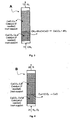
- a preferred aspect of the method of Figure 2 ins the use of reactor A as indicated in Figure 3 .
- the solids are not shifted between reactors, but the CaO-assisted reforming reaction front moves through the bed of solids, with the same conceptual result as that shown in Figure 2 .
- the natural gas and steam feed of reactor A joins a first part of the bed composed of CaCO 3 and Cu (product 13 in Figure 2 ), and, consequently, there is no reaction in that area.
- the overall reforming reaction with CH 4 vapour, with CO 2 absorption with CaO is only completed in the reaction front marked in Figure 3 .
- This front moves upward as the solid reagent (CaO) is used up, and, while this happens, the gaseous product at the outlet of said reactor (stream 12 in Figure 2 and 3 ) is primarily H 2 and H 2 O.
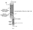
- the pressure conditions and the gaseous reagents in the bed must be changed in order to start a second reaction step by the solids in the bed (now primarily CaCO 3 and Cu), as shown in Figure 4 , which corresponds to the operation of reactor B in Figure 2 .
- the reactor of Figure 4 must operate at a high pressure in order to maximise the yield of the turbine (E) whereto it is connected, as shown in Figure 2 .
- the reaction conditions in reactor B must be adjusted in order for a reaction front to be formed where the complete oxidation reaction of Cu to CuO may take place, as indicated in Figure 4 .
- the oxidising gas mixture (stream 21) that enters the reactor must do so at moderate temperatures, which may be even close to ambient temperature, and always preferably less than 700°C, in order to reduce to a minimum the decomposition of the CaCO 3 that remains behind the reaction front.
- moderate temperatures which may be even close to ambient temperature, and always preferably less than 700°C
- the highly exothermal character of the oxidation reaction of Cu to CuO causes a rapid heating of the gas and the solids in the reaction front, which must be moderated in order for the temperatures in the upper part of the reaction front not to exceed the values that cause the rapid decomposition of CaCO 3 .
- This is achieved by making practically all the O 2 of stream 21 to disappear from the reaction front, by adequately controlling the O 2 concentration in 21 and its temperature, using recycle stream 25 and its temperature, by means of heat exchanger systems known in the state of the art.
- the resulting bed is a bed composed primarily of CuO and CaCO 3 .
- the last step of the method (represented by reactor C in Figure 2 ) begins.
- the bed has once again two areas divided by a reaction front wherein the rapid reduction of CuO to Cu with CH 4 takes place, to generate heat that may be used in the simultaneous decomposition reaction of CaCO 3 to CaO.
- This step takes place following a step of decompression and pre-heating of the bed (from its previous state, represented in Figure 4 ), such that the bed conditions are optimal for the rapid decomposition of CaCO 3 , as mentioned above.
- the result of this step is a bed composed of CaO and Cu that is ready for the beginning of a new cycle with the first bed reaction step (represented in Figure 3 ) of this invention method.
- a fuel gas preferred in this method is natural gas with a high concentration of CH 4 .
- Any other fuel gas for example, those resulting from any solid fuel gasification process (containing CO, H 2 , C n H m O y , H 2 O, N 2 , etc.), are adequate for reactor A, although only fuel gases without relevant N 2 contents are desireable for reactor C, in order to maintain a high concentration of CO 2 and H 2 O in stream 32.
- gases with a high CO content are especially favourable in reactor C due to the high enthalpy of reduction of CuO with CO.
- Natural gases with a certain CO 2 content may likewise be fed directly to reactor A (dry reforming of methane with CO 2 ) and reactor C.
- a second specific method included in this invention is particularly applicable to the gasification of solid fuels (biomass, reactive coals and others) to independently produce gases with a high concentration of hydrogen and a stream with a high concentration of CO 2 .
- Figure 6 shows a diagram of such a method, proposed as a system with three interconnected circulating fluidised-bed reactors with similar, albeit not identical, roles to those described in Figure 2 for the first method.
- the novelty of this method with respect to that described in Figure 2 is the integration of the solid fuel gasification step in fluidised-bed reactor A.
- Said reactor is fed with stream 12, containing a gasification agent (steam, air, oxygen or a mixture thereof), and stream 11, containing a solid fuel, preferably one with a high reactivity and a low content of ashes, such as certain types of biomass.
- a gasification agent steam, air, oxygen or a mixture thereof
- stream 11 containing a solid fuel, preferably one with a high reactivity and a low content of ashes, such as certain types of biomass.
- the gasification of solid fuels is a part of the state of the art, but a characteristic aspect of this method is that a stream of circulating solids with the adequate content of CaO and Cu is entering the reactor, with objectives similar to those described in the first specific method, such that, in stream 12, the fraction of H 2 is maximised with respect to other gasification gases and, in solid stream 13, most of the carbon originally contained in the solid fuel of stream 11 is found as CaCO 3 .
- Stream 22 leaves the system as a stream with a very high concentration of N 2 , a low concentration of O 2 that has not reacted with Cu, and CO 2 resulting from the slight, undesired decomposition of CaCO 3 into CaO at the operating temperature of B.
- Solid stream 26 leaves reactor B, ideally with a high concentration of CuO and CaCO 3 , and enters reactor C.
- This reactor is also fed with a mixture of fuel gas in nitrogen-free stream 31, in order to exothermally reduce CuO to Cu and decompose CaCO 3 .
- said fuel gas of stream 31 is a synthesis gas (CO and H 2 ) resulting from a separate gasification step (not included in the figure for the sake of simplicity) with techniques and devices already known in the state of the art.
- the gas product from gasifier A (stream 12) is free from N 2 (in the event that air has not been used in the gasification in A)
- said gas 12 may also be used as a gas for the reduction of CuO to Cu in reactor C.
- this second specific method is especially appealing for the case of biomass, since its high reactivity allows for high conversions of carbon to gases under the relatively mild gasification conditions in A, which allow for the capture of CO 2 by CaO.
- the permanent geological storage of the concentrated or easily susceptible to becoming concentrated CO 2 that leaves the system in stream 32 makes the system represented in Figure 5 a system with a net balance of negative emissions of CO 2 , as has already been described in CO 2 capture systems from biomasss of renewable origin.
- a third specific method included in this invention ( Figure 7 ) is particularlly applicable to the capture of CO 2 from fuel gases at atmospheric pressure produced by the combustion of any type of carbonaceous fuel (coal, natural gas, coke, fuel-oil, biomass, others) with air in new or already-existing large-scale devices.
- Said stream of combustion gases 71 is fed to a new reactor F, characteristic of this method, which contains the adequate quantities of CaO and CuO (unlike reactor A of Figure 2 , which includes Cu and not CuO).
- reactor F is a fixed-bed reactor operating at atmospheric pressure.
- FIG. 7 shows a diagram with continuous solid streams, which actually represent the movement of a reaction front in the corresponding fixed beds, in a similar manner to that explained in Figures 3, 4 and 5 for the first method described in this invention.
- reactor F is a hew reactor where the only reaction that should take place is the carbonatation of CaO to CaCO 3 with the CO 2 contained in the combustion gases of stream 71.
- the reactor operates at temperatures lower than 700°C, such that the equilibrium of CO 2 on CaO allows for high CO 2 capture efficiencies, and greater than 550°C, such that the recovery of the heat generated in the carbonatation in stream 72 may be more efficient.
- the combustion gases of stream 72 may be emitted to the atmosphere with a reduced CO 2 content.
- This reactor which is conceptually identical to that described in Figure 2 and in Figure 5 , is fed with a fuel gas that reduces CuO to Cu, operating under the conditions already described in the previous methods, and stream 32, which contains concentrated CO 2 , is obtained.
- the fuel gas of stream 31 is a synthesis gas (mixture of CO and H 2 ) with a low or zero content of nitrogen and other inerts, resulting from a gasification step with additional coal (step not incluided in the figure for the sake of simplicity).
- synthesis gas mixture of CO and H 2
- additional coal step not incluided in the figure for the sake of simplicity
- Reactor G is conceptually similar to the reactor B described in Figure 2 and in Figure 4 , but with a significant difference: since Cu is now accompanied by CaO and not CaCO 3 , it is no longer necessary to operate the reactor at moderate temperatures (as was the case with reactor B), in order to moderate the degree of decomposition of CaCO 3 .
- the reactions in reactor G may be designed at much higher temperatures (although preferably lower than 900°C, in order to prevent the deactivation of solids and undesired CuO reactions), which facilitates the high-energy yield gas expansion in a gas turbine E of the gas in stream 22 resulting from the reaction of the compressed air of stream 21 fed from compressor D to reactor G.
- air 21 that enters reactor G is mixed with a low-temperature N 2 recycle (stream 25) obtained from outlet stream 22, as was explained in previous invention methods, in order to moderate the temperatures in the Cu-to-CuO oxidation reaction front. It may also be necessary to raise the temperature of the gases fed to turbine E even further, in order to obtain even higher energy yields, if we optionally feed more air in stream 42 and more fuel gas under pressure in stream 51 to she turbine combustion chamber, as explained in previous methods of this invention.
- a fourth specific method is particularly applicable to the generation of electricity by means of already-existing combined cycles, wherein the combustion under pressure of gaseous carbonaceous fuels (natural gas, synthesis gas, other hydrocarbons) is performed, to be expanded in high-energy-yield turbines.
- gaseous carbonaceous fuels natural gas, synthesis gas, other hydrocarbons
- the fuel of stream 53 is burnt with the air under pressure of stream 43 resulting from one or more compressors in turbine E, such that the hot gases under pressure partially expand in said commercial gas turbine, but momentarily leave said turbine in stream 71 to be fed, at still a certain pressure, to carbonatation reactor F.
- This reactor F is a fixed-bed reactor and is similar to that described for the previous method, but, since it operates under pressure, it facilitates an effective absorption of CO 2 from the combustion gas by the CaO in the bed (the high partial pressures of CO 2 in stream 72 favour carbonatation, compensating for the typical low CO 2 molar fractions in combustion gas streams in natural gas turbines).
- the decarbonated gases resulting from reactor F may continue to expand in another section of gas turbine E or another type of turbine.
- the inlet conditions to said turbine may be adjusted with more fuel gas and air of stream 52, so as to obtain the maximum yields.
- the remaining block around reactors C and G is conceptually identical to that of the third specific method described above, and it is possible to enrich the air with N 2 thanks to a stream 42.
- a fifth specific method of the invention ( Figure 9 ) is applicable to the capture of the CO 2 generated in the calcination of materials with a certain content of CaCO 3 or other carbonates.
- the adequate mixture of a material (CaCO 3 is used here as an example) in a bed composed of particles or pellets containing CuO may allow for the calcination of the material, as described in previous methods, in a reactor C, producing a gas stream with a high concentration of CO 2 .
- the solid material resulting from said reaction (Cu and CaO if the initial material is CaCO 3 ) may be oxidised (Cu to CuO) depending on reactor G, thereby efficiently utilising, without CO 2 emissions, the energy initially contained in the fuel used for the reduction of CuO to Cu and the simultaneous decomposition of CaCO 3 .
- the figures represent, with numbered arrows, the solid and gas mass streams in methods with different reactors interconnected by said streams under continuous operation. But the same arrows may mean changes in step and reaction conditions in the same fixed solid bed alternating between different reaction modes, as explained in the description of the invention.
- the different types of reactors or reaction steps have been numbered with capital letters, by order of appearance in the description of the invention.
- This example corresponds to the first method of this invention represented in Figure 2 .
- the illustrative example has been proposed for the reforming of 1 kmol/h of CH 4 (stream 11) in a fixed-bed reactor (reactor A) which contains a solid with the following formulation by weight percent: 10% of CaO, 25% of Cu and 65% of Al 2 O 3 .
- reactor A contains a solid with the following formulation by weight percent: 10% of CaO, 25% of Cu and 65% of Al 2 O 3 .
- a molar flow rate of 3 kmol/h of steam is introduced in reactor A, which corresponds to a 50% excess with respect to the stoichiometry of the reforming and CO 2 absorption reactions described in this patent. This facilitates that all the equilibria involved in the system are more shifted toward the production of H 2 .
- reaction medium contains 1 kmol de CaO, which absorbs the CO 2 generated in the CH 4 reforming reaction for 1 hour, a gas stream is obtained which leaves said reactor A (stream 12) with a molar flow rate of H 2 of 4 kmol/h and a molar flow rate of steam of 1 kmol/h.
- Reactor A has been designed as an adiabatic equipment, since the slightly exothermal heat of reaction from the set of chemical reactions involved is invested in the heating of the reaction gases, in such a way that, despite the fact that the inlet temperature of the CH 4 -steam mixture is 200°C, the product gases (stream 12) leave the reactor at 655°C.
- reactor A operates at a pressure of 20 bar.
- Reactor A will be operative for the production of H 2 until all the CaO initially present (1 kmol) has been converted into CaCO 3 .
- the latter is the initial solid reagent of Figure 4 , which represents the second reaction step in this method.
- a depleted air stream (5% by volume of O 2 ) is made to pass, which comes from the mixture of compressed air obtained in compressor D and the partial recycling of gas product (stream 25, composed of 99.8% by volume of N 2 and 0.2% by volume of CO 2 , the latter resulting from the minority decomposition of CaCO 3 ) previously cooled to 350°C in appropriate heat recovery equipment that is a part of the state of the art.
- the selection of this temperature may vary depending on the temperature at which the compressed air leaves compressor D and the temperature at which the reaction front in reactor B is to be operated.
- the objective of passing this stream, which is so diluted in O 2 , through is to achieve the complete conversion of Cu to CuO (a very fast, exothermal) reaction at temperatures greater than 600°C), minimising the decomposition of CaCO 3 .
- the temperature of the oxidation reactor it was decided to set the temperature of the oxidation reactor at 725°C.
- This quantity of gas may be made to pass with high flow rates in short times or with low flow rates in long times, depending on numerous specific design variables, the estimation and practical implementation whereof are considered to be within the state of the art of the design of fixed-bed reactors with fast gas-solid reactions in "alternating pressure" reactors (PSA).
- PSA alternating pressure reactors
- the gas stream that leaves reactor B (stream 22) is, in turn, divided into two streams.
- Stream 25 (16.6 kmol/h) which, as discussed above, will be used to generate stream 21 of depleted air, jointly with stream 27 and the rest (4.1 kmol/h), join stream 52 resulting from extracting 3.35 kmol/h from stream 12.
- this stream is a mixture of H 2 (35.7% by volume), steam (8.9% by volume), CO 2 (0.1% by volume) and N 2 (55.3% by volume) at a temperature of 690°C and a pressure of 20 atmospheres. Subsequently, it is mixed with an air stream (stream 42) from the compressor, with a sufficient flow rate (10.5 kmol/h) for all the H 2 to be burnt in the gas turbine combustion chamber (turbine E) with 20% excess air.
- the temperature of the resulting stream (stream 23) reaches 1,530°C, and it may be subsequently expanded in high-yield turbine E, the design whereof is a part of the state of the art, to produce work and a stream of hot gases (710°C) at atmospheric pressure susceptible to being cooled in a heat recovery boiler with a suitable design that is a part of the state of the art of building boilers.
- the cold gases leave the system with the following composition by volume: 74.6% N 2 , 20.1% steam, 5.2% O 2 and 0.1 % CO 2 , the latter being the only loss of carbon to the atmosphere from the system proposed under the operating conditions described.
- This loss of carbon in the form of CO 2 has a molar flow rate of 0.01 kmol/h, a value that is much lower than the 1 kmol/h of CH 4 introduced into the reforming reactor (reactor A).
- the rest of stream 12 that has not been transferred to stream 52 (1.65 kmol/h) may be used, following a step consisting of heat recovery, cooling and condensation of water in accordance with methods described in the state of the art, to produce H 2 that may be used in other processes (1.32 kmol/h of H 2 ).
- the operation of reactor B culminates when all the Cu present has been converted into CuO, resulting in a bed at a temperature of 725°C, a pressure of 20 atmospheres and the following composition by weight percent: 15.5% of CaCO 3 , 0.1 % of CaO, 27.4% of CuO and 57.0% of Al 2 O 3 .
- An important operating variant of the oxidation reactor of this and other examples would consist of accepting greater losses of CO 2 by operating oxidation reactor B at a higher temperature. This would reduce the overall CO 2 capture efficiency, but this sacrifice would be accompanied by advantages such as a decrease in the need for reducing gas to be introduced into reactor C in order to take the temperature of the solids to calcination conditions, and an increase in the temperature of the gases that leave the oxidation reactor and are fed to the turbine.
- this variant it may be seen that, if a temperature of 815°C were allowed in reactor B, the decomposition of CaCO 3 would produce 0.046 kmol/h of CO 2 , which would be emitted to the atmosphere. This value continues to be low as compared to the 1 kmol/h of C fed to the system as CH 4 .
- the solid resulting from the previous oxidation step will be used as the starting raw material for the third, and last, step of the cycle, which is represented by stream 26 of Figure 2 and Figure 5 itself.
- This step is performed in the so-called reactor C, where the decomposition of CaCO 3 into CaO and CO 2 takes place (endothermal reaction) by means of the reduction of CuO to Cu (exothermal reaction), in accordance with the diagram in Figure 5 .
- reactor C where the decomposition of CaCO 3 into CaO and CO 2 takes place (endothermal reaction) by means of the reduction of CuO to Cu (exothermal reaction), in accordance with the diagram in Figure 5 .
- these reactions will be sufficiently rapid so as to assume the existence of a reaction front such as that shown in Figure 5 .
- This reducing agent may be CH 4 , synthesis gas (with variable CO:H 2 ratios, preferably high in CO due to the greater heat of reduction of CuO with said gas), any other reducing gas that is capable of exothermally reacting with CuO or mixtures of all of them.
- synthesis gas composed of 60% by volume of CO and 40% by volume of H 2 has been used, which could be obtained from the gasification or the reforming of solid, liquid or gaseous hydrocarbons.
- This illustrative example corresponds to the fourth method of this invention; which describes the separation of CO 2 diluted in a stream of combustion gases at atmospheric pressure resulting, for example, from a thermal power plant.
- the Figure that represents this example is that numbered as Figure 7 , and all the streams and reactors refer to said Figure.
- the reference is an existing coal combustion thermal power plant with a gross electric power of 350 MWe and a desulfurisation system for the entire installation prior to entry into the CO 2 capture system of this invention.
- a stream (stream 71) would enter the proposed CO 2 separation system with a molar flow rate of 46,729 kmol/h and the following composition by volume percent: 75.6% N 2 , 15.7% CO 2 , 6.1% H 2 O and 2.6% O 2 .
- This gas stream enters reactor F at a temperature of 150°C.
- Reactor F is a fixed bed the representation whereof would be similar to that shown in Figure 2 , except that, instead of Cu, there is CuO in the bed of solids. There it joins a solid at 600°C with the following formulation expressed in weight percent: 10% of active CaO, 40% of CuO and 50% of Al 2 O 3 .
- stream 72 which has a reduced CO 2 content (3% by volume), slightly greater than that set by equilibrium (1.9% by volume of CO 2 ) at the reactor outlet temperature (653°C).
- This first CO 2 capture operation culminates when all the CaO has been carbonated, in such a way that the resulting fixed bed has captured 0.063 kg of CO 2 for every kg of initial sorbent.
- the final solid has the following composition expressed in weight percent: 13.4% of CaCO 3 , 1.9% of CaO, 37.6% of CuO and 47.1% of Al 2 O 3 .
- Stream 72 may be emitted to the atmosphere following heat recovery in a boiler the characteristics and operation whereof are a part of the state of the art.
- the second reaction step undergone by the bed of solids is conceptually represented by stream 73, which enters reactor C in Figure 7 .
- the desired operation and reactions in reactor C are illustrated in Figure 4 .
- the regeneration of the calcium sorbent i.e. the decomposition of CaCO 3 into CaO and CO 2 , takes place.
- the energy necessary to perform this endothermal reaction will be supplied by the reduction of the CuO present in the sorbent by means of a reducing gas (stream 31).
- a reducing gas stream 31
- the reactor's operating temperature has been limited to 850°C. Under these conditions, the outlet partial pressure of CO 2 will be 0.48 atm.
- the 20,649 kmol/h of synthesis gas necessary to reduce all the CuO present in the sorbent, heat the bed and the gaseous reagents, and decompose the CaCO 3 may be obtained from the gasification or reforming of some fossil or biomass fuel, and the specific process to be used is a part of the state of the art of gasification and reforming processes.
- the reaction product obtained will be a stream of hot gas at 850°C and atmospheric pressure (stream 32) the molar flow rate whereof will depend on the composition of the synthesis gas selected to perform the reduction of CuO, it being possible to recover energy therefrom in an appropriate heat recovery boiler that is a part of the state of the art.
- the solid remains in the fixed-bed reactor at a temperature of 850°C, with the following composition by weight percent: 10.9% of CaO, 34.8% of Cu and 54.3% of Al 2 O 3 .
- step 3 which is conceptually represented by reactor G and stream 33 in Figure 7 .
- the desired operation and reactions in reactor G are similar to those of the reactor of Figure 3 , but with a significant difference: since there is no CaCO 3 in reactor G, it is not necessary to limit the operating temperature so much in order to limit the calcination of CaCO 3 , since the latter is already calcinated at the beginning of this step. Therefore, in order to perform the oxidation, compressed air (stream 21) at 20 atmospheres is used, which comes from compressor D.
- the concentration of O 2 in the stream that oxidises the CuO is reduced to 5% by volume, since the re-circulated gas is composed solely of N 2 , as reactor G is a fixed-bed reactor and the hypothesis that the reaction front consumes the O 2 in a narrow reacting band is valid.
- all the Cu is once again oxidised to CuO, and a solid is obtained with the following composition by weight percent: 10% of CaO, 40% of Cu and 50% of Al 2 O 3 , a composition that is identical to that of the sorbent necessary to perform step 1 (inlet solid into reactor F, stream 26).
- the hot gases that leave reactor 22 also do so at a high temperature (850°C) and a pressure of 20 atmospheres; for this reason, it is possible to recover part of this energy in a high-efficiency gas turbine (turbine E).
- turbine E high-efficiency gas turbine
- the supply of more air and synthesis gas (60% CO and 40% H 2 ) to the turbine combustion chamber is proposed; upon burning with air, this will raise the temperature of the final stream prior to entering the gas turbine to 1,550°C.
- a stream of combustion gases (stream 22) is obtained, at a temperature of 660°C and a molar flow rate of 65,700 kmol/h, wherefrom heat may be extracted in a recovery boiler with a design in accordance with the state of the art of this type of equipment.
Landscapes
- Chemical & Material Sciences (AREA)
- Engineering & Computer Science (AREA)
- Chemical Kinetics & Catalysis (AREA)
- Combustion & Propulsion (AREA)
- Mechanical Engineering (AREA)
- Analytical Chemistry (AREA)
- General Chemical & Material Sciences (AREA)
- Oil, Petroleum & Natural Gas (AREA)
- Health & Medical Sciences (AREA)
- Biomedical Technology (AREA)
- Physics & Mathematics (AREA)
- Environmental & Geological Engineering (AREA)
- Thermal Sciences (AREA)
- General Engineering & Computer Science (AREA)
- Hydrogen, Water And Hydrids (AREA)
- Carbon And Carbon Compounds (AREA)
- Industrial Gases (AREA)
- Treating Waste Gases (AREA)
- Gas Separation By Absorption (AREA)
Priority Applications (7)
| Application Number | Priority Date | Filing Date | Title |
|---|---|---|---|
| EP09382169A EP2305366B1 (de) | 2009-09-16 | 2009-09-16 | Verfahren zum Abscheiden von CO2 mittels CaO und der exothermen Reduktion eines Feststoffs |
| ES09382169T ES2384491T3 (es) | 2009-09-16 | 2009-09-16 | Procedimiento de captura de CO2 mediante CaO y la reducción exotérmica de un sólido |
| JP2012529307A JP2013504421A (ja) | 2009-09-16 | 2010-09-07 | CaO及び固体の発熱還元を用いたCO2の捕獲方法 |
| CA2773080A CA2773080C (en) | 2009-09-16 | 2010-09-07 | Method of capturing co2 by means of cao and the exothermic reduction of a solid |
| US13/390,244 US8506915B2 (en) | 2009-09-16 | 2010-09-07 | Method for recovering CO2 by means of CaO and the exothermic reduction of a solid |
| CN201080041211XA CN102655928A (zh) | 2009-09-16 | 2010-09-07 | 通过CaO和固体的放热还原回收CO2的方法 |
| PCT/ES2010/070585 WO2011033156A1 (es) | 2009-09-16 | 2010-09-07 | PROCEDIMIENTO DE CAPTURA DE CO2 MEDIANTE CaO Y LA REDUCCIÓN EXOTÉRMICA DE UN SÓLIDO |
Applications Claiming Priority (1)
| Application Number | Priority Date | Filing Date | Title |
|---|---|---|---|
| EP09382169A EP2305366B1 (de) | 2009-09-16 | 2009-09-16 | Verfahren zum Abscheiden von CO2 mittels CaO und der exothermen Reduktion eines Feststoffs |
Publications (2)
| Publication Number | Publication Date |
|---|---|
| EP2305366A1 true EP2305366A1 (de) | 2011-04-06 |
| EP2305366B1 EP2305366B1 (de) | 2012-05-30 |
Family
ID=41809227
Family Applications (1)
| Application Number | Title | Priority Date | Filing Date |
|---|---|---|---|
| EP09382169A Active EP2305366B1 (de) | 2009-09-16 | 2009-09-16 | Verfahren zum Abscheiden von CO2 mittels CaO und der exothermen Reduktion eines Feststoffs |
Country Status (7)
| Country | Link |
|---|---|
| US (1) | US8506915B2 (de) |
| EP (1) | EP2305366B1 (de) |
| JP (1) | JP2013504421A (de) |
| CN (1) | CN102655928A (de) |
| CA (1) | CA2773080C (de) |
| ES (1) | ES2384491T3 (de) |
| WO (1) | WO2011033156A1 (de) |
Cited By (8)
| Publication number | Priority date | Publication date | Assignee | Title |
|---|---|---|---|---|
| EP2529825A1 (de) * | 2011-06-01 | 2012-12-05 | Alstom Technology Ltd | CO2-Erfassung mit Karbonatschleife |
| WO2013003948A1 (en) * | 2011-07-04 | 2013-01-10 | Her Majesty The Queen In Right Of Canada As Represented By The Minister Of Natural Resources | Sorbent pellets including oxygen carriers |
| EP2623182A1 (de) * | 2012-02-06 | 2013-08-07 | Alstom Technology Ltd | Integriertes Verfahren und System zur Abscheidung von Kohlendioxid aus Emissionen |
| WO2014162075A1 (fr) * | 2013-04-05 | 2014-10-09 | IFP Energies Nouvelles | Procede et dispositif de combustion par boucle chimique de charges hydrocarbonees liquides |
| CN114432809A (zh) * | 2021-12-31 | 2022-05-06 | 安徽华塑股份有限公司 | 一种石灰窑二氧化碳捕集利用系统 |
| TWI791352B (zh) * | 2021-12-17 | 2023-02-01 | 台灣電力股份有限公司 | 用於分離二氧化碳之真空變壓吸附方法及其系統 |
| US11738307B2 (en) | 2017-03-09 | 2023-08-29 | Hot Lime Labs Limited | Method and apparatus for carbon dioxide capture and release |
| US11918970B2 (en) | 2021-03-04 | 2024-03-05 | Energy And Environmental Research Center Foundation | Methods of treating metal carbonate salts |
Families Citing this family (29)
| Publication number | Priority date | Publication date | Assignee | Title |
|---|---|---|---|---|
| JP5757630B2 (ja) * | 2012-02-13 | 2015-07-29 | 東京瓦斯株式会社 | 窒素製造に適したケミカルループ式燃焼装置とそれを用いた窒素および水素の製造方法 |
| CN103113919A (zh) * | 2013-03-07 | 2013-05-22 | 华北电力大学(保定) | 一种三反应器生物质热解系统及其工作方法 |
| US8728428B1 (en) * | 2013-03-13 | 2014-05-20 | Carbon Engineering Limited Partnership | Recovering a caustic solution via calcium carbonate crystal aggregates |
| US9550680B2 (en) * | 2013-06-21 | 2017-01-24 | General Electric Technology Gmbh | Chemical looping integration with a carbon dioxide gas purification unit |
| TWI588088B (zh) * | 2013-12-06 | 2017-06-21 | 財團法人工業技術研究院 | 合成氣的製備方法及其製備系統 |
| ES2547465B1 (es) * | 2014-03-04 | 2016-07-12 | Consejo Superior De Investigaciones Científicas (Csic) | Procedimiento de calcinación con producción de co2 puro mediantecombustión usando transportadores de o2 |
| US9637393B2 (en) | 2014-05-19 | 2017-05-02 | Carbon Engineering Limited Partnership | Recovering a caustic solution via calcium carbonate crystal aggregates |
| CN104449922B (zh) * | 2014-11-24 | 2016-09-07 | 北京交通大学 | 一种煤制洁净天然气系统 |
| JP6473345B2 (ja) * | 2015-02-26 | 2019-02-20 | 株式会社神戸製鋼所 | 水素製造装置及び水素製造方法 |
| CN104722197B (zh) * | 2015-04-08 | 2018-03-06 | 重庆大学 | 一种钙‑铜联合化学循环方法 |
| US10227234B2 (en) * | 2015-05-28 | 2019-03-12 | Gas Technology Institute | Hydrogen production via sorbent enhanced reforming with atmospheric calcination |
| WO2018187213A1 (en) * | 2017-04-03 | 2018-10-11 | Qatar Foundation For Education, Science And Community Development | System and method for carbon and syngas production |
| CN106986342B (zh) * | 2017-05-05 | 2019-03-22 | 湖南大学 | 制备合成气以及捕获和利用二氧化碳的方法和装置 |
| EP3572146A1 (de) | 2018-05-25 | 2019-11-27 | Consejo Superior De Investigaciones Científicas | Reaktor zur erwärmung eines gases und verwendungen davon |
| CA3134837C (en) * | 2019-04-05 | 2025-02-11 | ExxonMobil Technology and Engineering Company | HYDROGEN PRODUCTION WITH INTEGRATED CO2 CAPTURE |
| US12172127B2 (en) | 2019-12-03 | 2024-12-24 | 8 Rivers Capital, Llc | Direct capture of carbon dioxide |
| US12421110B2 (en) * | 2019-12-09 | 2025-09-23 | Universiteit Gent | Cyclic method of producing a hydrogen rich stream and/or a carbon monoxide rich stream |
| US12460143B2 (en) * | 2019-12-09 | 2025-11-04 | Universiteit Gent | Method to capture and utilize CO2 and an installation for capturing and utilizing CO2 |
| US11112174B1 (en) * | 2020-08-26 | 2021-09-07 | Next Carbon Solutions, Llc | Devices, systems, facilities, and processes for liquefied natural gas production |
| JP7654399B2 (ja) * | 2020-12-23 | 2025-04-01 | Ube三菱セメント株式会社 | 酸化カルシウムの製造方法 |
| US11858819B2 (en) | 2021-03-04 | 2024-01-02 | Energy And Environmental Research Center Foundation | Methods of producing a syngas composition |
| EP4098613A1 (de) * | 2021-06-03 | 2022-12-07 | Consejo Superior de Investigaciones Cientificas | Vakuumwechselkalzinierverfahren zur herstellung von hochreinem co2 aus caco3 |
| CN114409290B (zh) * | 2021-12-28 | 2022-11-04 | 北京北科环境工程有限公司 | 一种基于高炉煤气加热改性脱硫灰的装置与方法 |
| EP4253314A1 (de) | 2022-03-28 | 2023-10-04 | Saudi Arabian Mining Company (Ma'aden) | Integriertes verfahren zur aufwertung von minderwertigem kalkhaltigem phosphaterz mit geringem co2-ausstoss und geringem phosphorgipsabfall |
| EP4252889A1 (de) | 2022-03-28 | 2023-10-04 | Saudi Arabian Mining Company (Ma'aden) | Abscheidung von verschmutztem co2 mit aus der kalzinierung von phosphogips hergestelltem kalk unter verwendung von schwefel als nicht-co2 brennstoff |
| EP4371649A1 (de) * | 2022-11-18 | 2024-05-22 | Consejo Superior De Investigaciones Científicas (CSIC) | Dampfpartialdruckwechselkalzinierungsverfahren zur herstellung von hochreinem co2 aus caco3 |
| ES3037545T3 (en) | 2022-12-01 | 2025-10-02 | Consejo Superior Investigacion | Method of hydrogenation and calcination of caco3 with h2 |
| US12565423B2 (en) | 2023-01-26 | 2026-03-03 | Valero Services, Inc. | Process for producing hydrogen from natural gas |
| CN117000032B (zh) * | 2023-07-12 | 2025-11-18 | 国网浙江省电力有限公司电力科学研究院 | 耦合热化学储能的燃煤机组碳捕集系统及方法 |
Citations (6)
| Publication number | Priority date | Publication date | Assignee | Title |
|---|---|---|---|---|
| US5509362A (en) | 1992-12-11 | 1996-04-23 | Energy And Environmental Research Corporation | Method and apparatus for unmixed combustion as an alternative to fire |
| US5827496A (en) | 1992-12-11 | 1998-10-27 | Energy And Environmental Research Corp. | Methods and systems for heat transfer by unmixed combustion |
| US20030035770A1 (en) * | 2001-08-14 | 2003-02-20 | Cole Jerald A. | Process for separating synthesis gas into fuel cell quality hydrogen and sequestration ready carbon dioxide |
| EP0871537B1 (de) * | 1995-04-25 | 2003-11-12 | Energy And Environmental Research Corporation | Verfahren und System zur Wärmeübertragung mit Hilfe eines Materials für die unvermischte Verbrennung von Kraftstoff und Luft |
| US20040237404A1 (en) | 2003-05-29 | 2004-12-02 | Alstom (Switzerland) Ltd | Hot solids gasifier with CO2 removal and hydrogen production |
| US6911057B2 (en) | 2001-07-31 | 2005-06-28 | General Electric Company | Apparatus for converting coal into fuel cell quality hydrogen and sequestration-ready carbon dioxide |
Family Cites Families (2)
| Publication number | Priority date | Publication date | Assignee | Title |
|---|---|---|---|---|
| JP3816681B2 (ja) * | 1998-11-09 | 2006-08-30 | 東芝三菱電機産業システム株式会社 | 含炭素燃料の炭素分離装置 |
| US20110124748A1 (en) * | 2009-08-18 | 2011-05-26 | Mr. Lai O. kuku | Coal and Biomass Conversion to Multiple Cleaner Energy Solutions System producing Hydrogen, Synthetic Fuels, Oils and Lubricants, Substitute Natural Gas and Clean Electricity |
-
2009
- 2009-09-16 ES ES09382169T patent/ES2384491T3/es active Active
- 2009-09-16 EP EP09382169A patent/EP2305366B1/de active Active
-
2010
- 2010-09-07 WO PCT/ES2010/070585 patent/WO2011033156A1/es not_active Ceased
- 2010-09-07 CN CN201080041211XA patent/CN102655928A/zh active Pending
- 2010-09-07 US US13/390,244 patent/US8506915B2/en not_active Expired - Fee Related
- 2010-09-07 JP JP2012529307A patent/JP2013504421A/ja active Pending
- 2010-09-07 CA CA2773080A patent/CA2773080C/en active Active
Patent Citations (6)
| Publication number | Priority date | Publication date | Assignee | Title |
|---|---|---|---|---|
| US5509362A (en) | 1992-12-11 | 1996-04-23 | Energy And Environmental Research Corporation | Method and apparatus for unmixed combustion as an alternative to fire |
| US5827496A (en) | 1992-12-11 | 1998-10-27 | Energy And Environmental Research Corp. | Methods and systems for heat transfer by unmixed combustion |
| EP0871537B1 (de) * | 1995-04-25 | 2003-11-12 | Energy And Environmental Research Corporation | Verfahren und System zur Wärmeübertragung mit Hilfe eines Materials für die unvermischte Verbrennung von Kraftstoff und Luft |
| US6911057B2 (en) | 2001-07-31 | 2005-06-28 | General Electric Company | Apparatus for converting coal into fuel cell quality hydrogen and sequestration-ready carbon dioxide |
| US20030035770A1 (en) * | 2001-08-14 | 2003-02-20 | Cole Jerald A. | Process for separating synthesis gas into fuel cell quality hydrogen and sequestration ready carbon dioxide |
| US20040237404A1 (en) | 2003-05-29 | 2004-12-02 | Alstom (Switzerland) Ltd | Hot solids gasifier with CO2 removal and hydrogen production |
Non-Patent Citations (4)
| Title |
|---|
| ABANADES, J.C.; ANTHONY, E.J.; WANG, J.; OAKEY, J.E., ENVIRON. SCI. TECH., vol. 39, no. 8, 2005, pages 2861 |
| D. P. HARRISON: "Sorption-Enhanced Hydrogen Production: A Review", IND. ENG. CHEM. RES., vol. 47, 2008, pages 6486 - 6501 |
| JINSHENG WANG; EDWARD J. ANTHONY, APPLIED ENERGY, vol. 85, no. 2-3, 2008, pages 73 - 79 |
| MOHAMMAD M. HOSSAIN; HUGO . DE LASA, CHEM ENG. SCI., vol. 63, 2008, pages 4433 - 4451 |
Cited By (12)
| Publication number | Priority date | Publication date | Assignee | Title |
|---|---|---|---|---|
| EP2529825A1 (de) * | 2011-06-01 | 2012-12-05 | Alstom Technology Ltd | CO2-Erfassung mit Karbonatschleife |
| WO2012164370A1 (en) * | 2011-06-01 | 2012-12-06 | Alstom Technology Ltd | Co2 capture with carbonate looping |
| WO2013003948A1 (en) * | 2011-07-04 | 2013-01-10 | Her Majesty The Queen In Right Of Canada As Represented By The Minister Of Natural Resources | Sorbent pellets including oxygen carriers |
| EP2623182A1 (de) * | 2012-02-06 | 2013-08-07 | Alstom Technology Ltd | Integriertes Verfahren und System zur Abscheidung von Kohlendioxid aus Emissionen |
| WO2013118035A1 (en) * | 2012-02-06 | 2013-08-15 | Alstom Technology Ltd | Integrated process and system for carbon dioxide emission capture |
| WO2014162075A1 (fr) * | 2013-04-05 | 2014-10-09 | IFP Energies Nouvelles | Procede et dispositif de combustion par boucle chimique de charges hydrocarbonees liquides |
| FR3004126A1 (fr) * | 2013-04-05 | 2014-10-10 | IFP Energies Nouvelles | Procede et dispositif de combustion par boucle chimique de charges hydrocarbonees liquides |
| US10317072B2 (en) | 2013-04-05 | 2019-06-11 | IFP Energies Nouvelles | Method and device for chemical loop combustion of liquid hydrocarbon feedstocks |
| US11738307B2 (en) | 2017-03-09 | 2023-08-29 | Hot Lime Labs Limited | Method and apparatus for carbon dioxide capture and release |
| US11918970B2 (en) | 2021-03-04 | 2024-03-05 | Energy And Environmental Research Center Foundation | Methods of treating metal carbonate salts |
| TWI791352B (zh) * | 2021-12-17 | 2023-02-01 | 台灣電力股份有限公司 | 用於分離二氧化碳之真空變壓吸附方法及其系統 |
| CN114432809A (zh) * | 2021-12-31 | 2022-05-06 | 安徽华塑股份有限公司 | 一种石灰窑二氧化碳捕集利用系统 |
Also Published As
| Publication number | Publication date |
|---|---|
| WO2011033156A1 (es) | 2011-03-24 |
| EP2305366B1 (de) | 2012-05-30 |
| CN102655928A (zh) | 2012-09-05 |
| US20120230897A1 (en) | 2012-09-13 |
| ES2384491T3 (es) | 2012-07-05 |
| US8506915B2 (en) | 2013-08-13 |
| JP2013504421A (ja) | 2013-02-07 |
| CA2773080A1 (en) | 2011-03-24 |
| CA2773080C (en) | 2014-05-06 |
Similar Documents
| Publication | Publication Date | Title |
|---|---|---|
| EP2305366B1 (de) | Verfahren zum Abscheiden von CO2 mittels CaO und der exothermen Reduktion eines Feststoffs | |
| Yan et al. | Techno-economic analysis of low-carbon hydrogen production by sorption enhanced steam methane reforming (SE-SMR) processes | |
| Yan et al. | Process simulations of blue hydrogen production by upgraded sorption enhanced steam methane reforming (SE-SMR) processes | |
| Fernández et al. | Conceptual design of a hydrogen production process from natural gas with CO2 capture using a Ca–Cu chemical loop | |
| US8496909B2 (en) | Calcium looping process for high purity hydrogen production integrated with capture of carbon dioxide, sulfur and halides | |
| US8419813B2 (en) | Integrated energy and/or synthesis gas production method by in-situ oxygen production, chemical looping combustion and gasification | |
| Fan et al. | Utilization of chemical looping strategy in coal gasification processes | |
| Antzara et al. | Thermodynamic analysis of hydrogen production via chemical looping steam methane reforming coupled with in situ CO2 capture | |
| Moghtaderi | Review of the recent chemical looping process developments for novel energy and fuel applications | |
| CN101987277B (zh) | 从燃烧废气中分离出co2的方法和装置 | |
| EP2490792B1 (de) | System und verfahren zur verarbeitung eines eingangsbrenngases und dampf zur herstellung von kohlenstoffdioxid sowie ausgangsbrenngas | |
| Zhu et al. | Thermodynamic analysis of H2 production from CaO sorption‐enhanced methane steam reforming thermally coupled with chemical looping combustion as a novel technology | |
| AU2012313348A1 (en) | Integrated chemical looping air separation in large-scale oxy-fuel plants | |
| WO2011108546A1 (ja) | 高炉の操業方法、製鉄所の操業方法、および酸化炭素含有ガスの利用方法 | |
| Fernández et al. | Sorption enhanced reforming of methane combined with an iron oxide chemical loop for the production of hydrogen with CO2 capture: Conceptual design and operation strategy | |
| AU2012315483B2 (en) | Chemical looping removal of ventilation air methane | |
| Chen et al. | Application of chemical looping air separation for MILD oxy-combustion: identifying a suitable operational region | |
| CN103249816B (zh) | 生成气体的重整方法和装置 | |
| US12161969B2 (en) | Redox reaction facilitated carbon dioxide capture from flue gas and conversion to carbon monoxide | |
| Abbas et al. | A Ca-Cu chemical loop process for CO2 capture in steel mills: system performance analysis | |
| Manzolini et al. | Integration of SEWGS for carbon capture in natural gas combined cycle. Part A: Thermodynamic performances | |
| Shah et al. | The Role of Chemical Looping in Industrial Gas Separation | |
| CN118079589A (zh) | 一种基于燃料分级转化耦合化学链燃烧的co2捕集方法及系统 | |
| Fernández et al. | Novel process for hydrogen production through the sorption enhanced reforming of methane combined with chemical looping combustion | |
| Kaini et al. | Thermodynamic evaluation of hydrogen production from methane |
Legal Events
| Date | Code | Title | Description |
|---|---|---|---|
| PUAI | Public reference made under article 153(3) epc to a published international application that has entered the european phase |
Free format text: ORIGINAL CODE: 0009012 |
|
| AK | Designated contracting states |
Kind code of ref document: A1 Designated state(s): AT BE BG CH CY CZ DE DK EE ES FI FR GB GR HR HU IE IS IT LI LT LU LV MC MK MT NL NO PL PT RO SE SI SK SM TR |
|
| AX | Request for extension of the european patent |
Extension state: AL BA RS |
|
| 17P | Request for examination filed |
Effective date: 20111007 |
|
| GRAP | Despatch of communication of intention to grant a patent |
Free format text: ORIGINAL CODE: EPIDOSNIGR1 |
|
| RIC1 | Information provided on ipc code assigned before grant |
Ipc: F24J 1/00 20060101ALI20111110BHEP Ipc: B01D 53/62 20060101AFI20111110BHEP |
|
| GRAS | Grant fee paid |
Free format text: ORIGINAL CODE: EPIDOSNIGR3 |
|
| GRAA | (expected) grant |
Free format text: ORIGINAL CODE: 0009210 |
|
| AK | Designated contracting states |
Kind code of ref document: B1 Designated state(s): AT BE BG CH CY CZ DE DK EE ES FI FR GB GR HR HU IE IS IT LI LT LU LV MC MK MT NL NO PL PT RO SE SI SK SM TR |
|
| REG | Reference to a national code |
Ref country code: GB Ref legal event code: FG4D |
|
| REG | Reference to a national code |
Ref country code: CH Ref legal event code: EP |
|
| REG | Reference to a national code |
Ref country code: AT Ref legal event code: REF Ref document number: 559775 Country of ref document: AT Kind code of ref document: T Effective date: 20120615 |
|
| REG | Reference to a national code |
Ref country code: IE Ref legal event code: FG4D |
|
| REG | Reference to a national code |
Ref country code: ES Ref legal event code: FG2A Ref document number: 2384491 Country of ref document: ES Kind code of ref document: T3 Effective date: 20120705 |
|
| REG | Reference to a national code |
Ref country code: DE Ref legal event code: R096 Ref document number: 602009007326 Country of ref document: DE Effective date: 20120802 |
|
| REG | Reference to a national code |
Ref country code: NL Ref legal event code: T3 |
|
| REG | Reference to a national code |
Ref country code: LT Ref legal event code: MG4D Effective date: 20120530 |
|
| PG25 | Lapsed in a contracting state [announced via postgrant information from national office to epo] |
Ref country code: FI Free format text: LAPSE BECAUSE OF FAILURE TO SUBMIT A TRANSLATION OF THE DESCRIPTION OR TO PAY THE FEE WITHIN THE PRESCRIBED TIME-LIMIT Effective date: 20120530 Ref country code: LT Free format text: LAPSE BECAUSE OF FAILURE TO SUBMIT A TRANSLATION OF THE DESCRIPTION OR TO PAY THE FEE WITHIN THE PRESCRIBED TIME-LIMIT Effective date: 20120530 Ref country code: SE Free format text: LAPSE BECAUSE OF FAILURE TO SUBMIT A TRANSLATION OF THE DESCRIPTION OR TO PAY THE FEE WITHIN THE PRESCRIBED TIME-LIMIT Effective date: 20120530 Ref country code: CY Free format text: LAPSE BECAUSE OF FAILURE TO SUBMIT A TRANSLATION OF THE DESCRIPTION OR TO PAY THE FEE WITHIN THE PRESCRIBED TIME-LIMIT Effective date: 20120530 Ref country code: IS Free format text: LAPSE BECAUSE OF FAILURE TO SUBMIT A TRANSLATION OF THE DESCRIPTION OR TO PAY THE FEE WITHIN THE PRESCRIBED TIME-LIMIT Effective date: 20120930 Ref country code: NO Free format text: LAPSE BECAUSE OF FAILURE TO SUBMIT A TRANSLATION OF THE DESCRIPTION OR TO PAY THE FEE WITHIN THE PRESCRIBED TIME-LIMIT Effective date: 20120830 |
|
| REG | Reference to a national code |
Ref country code: AT Ref legal event code: MK05 Ref document number: 559775 Country of ref document: AT Kind code of ref document: T Effective date: 20120530 |
|
| PG25 | Lapsed in a contracting state [announced via postgrant information from national office to epo] |
Ref country code: GR Free format text: LAPSE BECAUSE OF FAILURE TO SUBMIT A TRANSLATION OF THE DESCRIPTION OR TO PAY THE FEE WITHIN THE PRESCRIBED TIME-LIMIT Effective date: 20120831 Ref country code: SI Free format text: LAPSE BECAUSE OF FAILURE TO SUBMIT A TRANSLATION OF THE DESCRIPTION OR TO PAY THE FEE WITHIN THE PRESCRIBED TIME-LIMIT Effective date: 20120530 Ref country code: LV Free format text: LAPSE BECAUSE OF FAILURE TO SUBMIT A TRANSLATION OF THE DESCRIPTION OR TO PAY THE FEE WITHIN THE PRESCRIBED TIME-LIMIT Effective date: 20120530 Ref country code: HR Free format text: LAPSE BECAUSE OF FAILURE TO SUBMIT A TRANSLATION OF THE DESCRIPTION OR TO PAY THE FEE WITHIN THE PRESCRIBED TIME-LIMIT Effective date: 20120530 |
|
| PG25 | Lapsed in a contracting state [announced via postgrant information from national office to epo] |
Ref country code: BE Free format text: LAPSE BECAUSE OF FAILURE TO SUBMIT A TRANSLATION OF THE DESCRIPTION OR TO PAY THE FEE WITHIN THE PRESCRIBED TIME-LIMIT Effective date: 20120530 |
|
| PG25 | Lapsed in a contracting state [announced via postgrant information from national office to epo] |
Ref country code: CZ Free format text: LAPSE BECAUSE OF FAILURE TO SUBMIT A TRANSLATION OF THE DESCRIPTION OR TO PAY THE FEE WITHIN THE PRESCRIBED TIME-LIMIT Effective date: 20120530 Ref country code: RO Free format text: LAPSE BECAUSE OF FAILURE TO SUBMIT A TRANSLATION OF THE DESCRIPTION OR TO PAY THE FEE WITHIN THE PRESCRIBED TIME-LIMIT Effective date: 20120530 Ref country code: SK Free format text: LAPSE BECAUSE OF FAILURE TO SUBMIT A TRANSLATION OF THE DESCRIPTION OR TO PAY THE FEE WITHIN THE PRESCRIBED TIME-LIMIT Effective date: 20120530 Ref country code: DK Free format text: LAPSE BECAUSE OF FAILURE TO SUBMIT A TRANSLATION OF THE DESCRIPTION OR TO PAY THE FEE WITHIN THE PRESCRIBED TIME-LIMIT Effective date: 20120530 Ref country code: EE Free format text: LAPSE BECAUSE OF FAILURE TO SUBMIT A TRANSLATION OF THE DESCRIPTION OR TO PAY THE FEE WITHIN THE PRESCRIBED TIME-LIMIT Effective date: 20120530 Ref country code: AT Free format text: LAPSE BECAUSE OF FAILURE TO SUBMIT A TRANSLATION OF THE DESCRIPTION OR TO PAY THE FEE WITHIN THE PRESCRIBED TIME-LIMIT Effective date: 20120530 |
|
| PG25 | Lapsed in a contracting state [announced via postgrant information from national office to epo] |
Ref country code: PT Free format text: LAPSE BECAUSE OF FAILURE TO SUBMIT A TRANSLATION OF THE DESCRIPTION OR TO PAY THE FEE WITHIN THE PRESCRIBED TIME-LIMIT Effective date: 20121001 Ref country code: PL Free format text: LAPSE BECAUSE OF FAILURE TO SUBMIT A TRANSLATION OF THE DESCRIPTION OR TO PAY THE FEE WITHIN THE PRESCRIBED TIME-LIMIT Effective date: 20120530 |
|
| PLBE | No opposition filed within time limit |
Free format text: ORIGINAL CODE: 0009261 |
|
| STAA | Information on the status of an ep patent application or granted ep patent |
Free format text: STATUS: NO OPPOSITION FILED WITHIN TIME LIMIT |
|
| PG25 | Lapsed in a contracting state [announced via postgrant information from national office to epo] |
Ref country code: MC Free format text: LAPSE BECAUSE OF NON-PAYMENT OF DUE FEES Effective date: 20120930 |
|
| 26N | No opposition filed |
Effective date: 20130301 |
|
| REG | Reference to a national code |
Ref country code: IE Ref legal event code: MM4A |
|
| REG | Reference to a national code |
Ref country code: DE Ref legal event code: R097 Ref document number: 602009007326 Country of ref document: DE Effective date: 20130301 |
|
| PG25 | Lapsed in a contracting state [announced via postgrant information from national office to epo] |
Ref country code: BG Free format text: LAPSE BECAUSE OF FAILURE TO SUBMIT A TRANSLATION OF THE DESCRIPTION OR TO PAY THE FEE WITHIN THE PRESCRIBED TIME-LIMIT Effective date: 20120830 Ref country code: IE Free format text: LAPSE BECAUSE OF NON-PAYMENT OF DUE FEES Effective date: 20120916 |
|
| REG | Reference to a national code |
Ref country code: ES Ref legal event code: FD2A Effective date: 20131021 |
|
| PG25 | Lapsed in a contracting state [announced via postgrant information from national office to epo] |
Ref country code: ES Free format text: LAPSE BECAUSE OF NON-PAYMENT OF DUE FEES Effective date: 20120917 |
|
| PG25 | Lapsed in a contracting state [announced via postgrant information from national office to epo] |
Ref country code: MT Free format text: LAPSE BECAUSE OF FAILURE TO SUBMIT A TRANSLATION OF THE DESCRIPTION OR TO PAY THE FEE WITHIN THE PRESCRIBED TIME-LIMIT Effective date: 20120530 |
|
| PG25 | Lapsed in a contracting state [announced via postgrant information from national office to epo] |
Ref country code: TR Free format text: LAPSE BECAUSE OF FAILURE TO SUBMIT A TRANSLATION OF THE DESCRIPTION OR TO PAY THE FEE WITHIN THE PRESCRIBED TIME-LIMIT Effective date: 20120530 |
|
| REG | Reference to a national code |
Ref country code: CH Ref legal event code: PL |
|
| PG25 | Lapsed in a contracting state [announced via postgrant information from national office to epo] |
Ref country code: LU Free format text: LAPSE BECAUSE OF NON-PAYMENT OF DUE FEES Effective date: 20120916 Ref country code: SM Free format text: LAPSE BECAUSE OF FAILURE TO SUBMIT A TRANSLATION OF THE DESCRIPTION OR TO PAY THE FEE WITHIN THE PRESCRIBED TIME-LIMIT Effective date: 20120530 |
|
| PG25 | Lapsed in a contracting state [announced via postgrant information from national office to epo] |
Ref country code: CH Free format text: LAPSE BECAUSE OF NON-PAYMENT OF DUE FEES Effective date: 20130930 Ref country code: HU Free format text: LAPSE BECAUSE OF FAILURE TO SUBMIT A TRANSLATION OF THE DESCRIPTION OR TO PAY THE FEE WITHIN THE PRESCRIBED TIME-LIMIT Effective date: 20090916 Ref country code: LI Free format text: LAPSE BECAUSE OF NON-PAYMENT OF DUE FEES Effective date: 20130930 |
|
| PG25 | Lapsed in a contracting state [announced via postgrant information from national office to epo] |
Ref country code: MK Free format text: LAPSE BECAUSE OF FAILURE TO SUBMIT A TRANSLATION OF THE DESCRIPTION OR TO PAY THE FEE WITHIN THE PRESCRIBED TIME-LIMIT Effective date: 20120530 |
|
| REG | Reference to a national code |
Ref country code: FR Ref legal event code: PLFP Year of fee payment: 7 |
|
| REG | Reference to a national code |
Ref country code: FR Ref legal event code: PLFP Year of fee payment: 8 |
|
| REG | Reference to a national code |
Ref country code: FR Ref legal event code: PLFP Year of fee payment: 9 |
|
| REG | Reference to a national code |
Ref country code: FR Ref legal event code: PLFP Year of fee payment: 10 |
|
| PGFP | Annual fee paid to national office [announced via postgrant information from national office to epo] |
Ref country code: GB Payment date: 20220927 Year of fee payment: 14 Ref country code: DE Payment date: 20220928 Year of fee payment: 14 |
|
| PGFP | Annual fee paid to national office [announced via postgrant information from national office to epo] |
Ref country code: FR Payment date: 20220926 Year of fee payment: 14 |
|
| PGFP | Annual fee paid to national office [announced via postgrant information from national office to epo] |
Ref country code: IT Payment date: 20220926 Year of fee payment: 14 |
|
| P01 | Opt-out of the competence of the unified patent court (upc) registered |
Effective date: 20230322 |
|
| REG | Reference to a national code |
Ref country code: DE Ref legal event code: R119 Ref document number: 602009007326 Country of ref document: DE |
|
| GBPC | Gb: european patent ceased through non-payment of renewal fee |
Effective date: 20230916 |
|
| PG25 | Lapsed in a contracting state [announced via postgrant information from national office to epo] |
Ref country code: GB Free format text: LAPSE BECAUSE OF NON-PAYMENT OF DUE FEES Effective date: 20230916 |
|
| PG25 | Lapsed in a contracting state [announced via postgrant information from national office to epo] |
Ref country code: GB Free format text: LAPSE BECAUSE OF NON-PAYMENT OF DUE FEES Effective date: 20230916 Ref country code: FR Free format text: LAPSE BECAUSE OF NON-PAYMENT OF DUE FEES Effective date: 20230930 Ref country code: DE Free format text: LAPSE BECAUSE OF NON-PAYMENT OF DUE FEES Effective date: 20240403 |
|
| PGFP | Annual fee paid to national office [announced via postgrant information from national office to epo] |
Ref country code: NL Payment date: 20240820 Year of fee payment: 16 |
|
| PG25 | Lapsed in a contracting state [announced via postgrant information from national office to epo] |
Ref country code: IT Free format text: LAPSE BECAUSE OF NON-PAYMENT OF DUE FEES Effective date: 20230916 |
|
| PG25 | Lapsed in a contracting state [announced via postgrant information from national office to epo] |
Ref country code: IT Free format text: LAPSE BECAUSE OF NON-PAYMENT OF DUE FEES Effective date: 20230916 |