EP2305561A1 - Luftfahrzeugsitz mit Mitteln zum Schützen des Passagiers im Unfallsfall - Google Patents
Luftfahrzeugsitz mit Mitteln zum Schützen des Passagiers im Unfallsfall Download PDFInfo
- Publication number
- EP2305561A1 EP2305561A1 EP10009473A EP10009473A EP2305561A1 EP 2305561 A1 EP2305561 A1 EP 2305561A1 EP 10009473 A EP10009473 A EP 10009473A EP 10009473 A EP10009473 A EP 10009473A EP 2305561 A1 EP2305561 A1 EP 2305561A1
- Authority
- EP
- European Patent Office
- Prior art keywords
- tub
- seat according
- seat
- studs
- backrest
- Prior art date
- Legal status (The legal status is an assumption and is not a legal conclusion. Google has not performed a legal analysis and makes no representation as to the accuracy of the status listed.)
- Granted
Links
Images
Classifications
-
- B—PERFORMING OPERATIONS; TRANSPORTING
- B64—AIRCRAFT; AVIATION; COSMONAUTICS
- B64D—EQUIPMENT FOR FITTING IN OR TO AIRCRAFT; FLIGHT SUITS; PARACHUTES; ARRANGEMENT OR MOUNTING OF POWER PLANTS OR PROPULSION TRANSMISSIONS IN AIRCRAFT
- B64D11/00—Passenger or crew accommodation; Flight-deck installations not otherwise provided for
- B64D11/06—Arrangements of seats, or adaptations or details specially adapted for aircraft seats
- B64D11/0689—Arrangements of seats, or adaptations or details specially adapted for aircraft seats specially adapted for pilots
-
- B—PERFORMING OPERATIONS; TRANSPORTING
- B64—AIRCRAFT; AVIATION; COSMONAUTICS
- B64D—EQUIPMENT FOR FITTING IN OR TO AIRCRAFT; FLIGHT SUITS; PARACHUTES; ARRANGEMENT OR MOUNTING OF POWER PLANTS OR PROPULSION TRANSMISSIONS IN AIRCRAFT
- B64D11/00—Passenger or crew accommodation; Flight-deck installations not otherwise provided for
- B64D11/06—Arrangements of seats, or adaptations or details specially adapted for aircraft seats
- B64D11/0619—Arrangements of seats, or adaptations or details specially adapted for aircraft seats with energy absorbing means specially adapted for mitigating impact loads for passenger seats, e.g. at a crash
Definitions
- the present invention is in the field of motorized flying devices, aircraft and rotorcraft in particular, and more particularly in the field of accessories equipping such devices. It relates to a seat for powered flying devices, which incorporates means of protection of passengers in case of violent shocks and / or a sudden change of pace that the aircraft suffered, especially during a crash.
- the seats for motorized powered aircraft incorporate means of protection of the passenger installed on the seat in the event of a crash. It will be understood by passenger any individual on board the aircraft, whether pilot or person transported.
- protection means are usually constituted by energy absorption means which are able to compensate for the stresses experienced by the seat when it is subjected to violent shocks and / or sudden deceleration, especially in the event of a crash.
- the seat is commonly organized to compensate for deformations of the floor of the aircraft, and to absorb the energy induced by the forces to which the aircraft is generally subjected during the crash.
- the seat combines a base and a tub consisting of a seat with a backrest.
- the base is anchored to the floor of the device via longitudinal members, and has amounts that are integral with the side members and which are jointly carrying the tub.
- the connection between the tub and the uprights is of the type by broaching or the like, being carried out by means of studs which are mounted jointly engaged on the backrest and on the uprights.
- the directions and positions defined as lateral associated with side, longitudinal associated with front and rear, transverse and in height are to be considered in relation to the position of the passenger on the seat.
- the object of the present invention is to provide a seat for motorized flying apparatus, which incorporates means of protection of the passenger installed on the seat in the event of violent shock to the aircraft, particularly in the event of a crash. It is more particularly targeted by the present invention to provide such a seat incorporating a mechanism specifically dedicated to the protection of the passenger against a deformation of the floor, regardless of the constraints that produce such a deformation. Such a mechanism is sought so that it meets at least the requirements and the problems to be solved and the difficulties to be overcome that have been set forth. Such a mechanism is also sought so that it is advantageously able to operate independently and / or in cooperation with another mechanism specifically dedicated to the protection of the passenger with regard to a sudden change of pace of the device in case of crash.
- the seat of the present invention is arranged to equip a motorized flying device, such as an airplane or a rotorcraft, to protect a passenger installed on the seat in case of a sudden change of pace and / or in case of shock during a crash of the device.
- a motorized flying device such as an airplane or a rotorcraft
- the shocks to which it is subjected are mainly mainly exercised along the general axis of gravity, but also in transverse directions that may be arbitrary with respect to this general axis of gravity.
- These shocks subject the seat to significant constraints while nevertheless having front and / or side components according to the position and orientation of installation of the seat in the apparatus, and according to the orientation of the apparatus relative to the ground when crash.
- the seat mainly includes a tub in hyperstatic maintenance on a base.
- the tub is composed of a seat with a backrest and the base includes anchor rails of the seat in the position of use on an installation plan, including the floor of the device.
- the hyperstatic maintenance of the tub corresponds more particularly to its support by the base from several points or zones of taken which are distributed laterally and according to the height of the tub.
- These gripping points are preferably four in number, and are distributed in laterally spaced pairs.
- the grip points of each pair are more particularly distributed in the upper zone and in the lower zone of the bucket in the position of use of the seat, and more specifically in the upper zone and in the lower zone of the backrest.
- Uprights are respectively integral with the longitudinal members that includes the base, and are jointly carrying pinning of the tub via axially extended studs.
- One end of each of the studs is engaged on a backrest frame while their other end is engaged on a dedicated post.
- the uprights are laterally spaced to distribute the said grip points, being preferably arranged at the rear of the tub.
- the armature equipping the backrest is likely to be mainly composed of a pair of beams or the like on the seat and backrest, each of these beams being assigned to a dedicated amount to support the bucket maintenance hyperstatic.
- the seat of the present invention is more specifically equipped with a first articulated mechanism of geometric compensation of a deformation of the floor regardless of the orientation of the forces to which the base is subjected and regardless of the magnitude of these efforts in a predetermined stress range.
- this first mechanism is an articulated mechanism that is specifically adapted to compensate for a deformation of the floor, so that the seating plane for the passenger remains substantially constant in case of a deformation of the base.
- Such a deformation of the base corresponds to that currently accepted in the field of flying aircraft with regard to the safety of the passenger, namely an angular tilting of the side members on either side of the seat installation plan of the order of 10 °.
- the first mechanism proposed by the present invention associates a ball joint mounting of the studs with their arrangement in axial deformation.
- the ball joint mounting of the studs is preferably performed on said dedicated amount, but may be indifferently provided on the dedicated amount or on the backrest frame.
- the arrangement in axial deformation of the studs is more particularly formed between antagonistic axial supports that they take against the backrest frame and the dedicated amount.
- the mounting ball studs and their ability to deform axially accordingly compensates for a deformation of the floor, whatever this deformation induced by forces that can be exerted in any direction and randomly.
- a passenger installed on the seat is protected from any deformation of the floor, including a deformation which has not been the subject of a preliminary examination, in particular by test.
- the structure of the first mechanism is simple, easy to obtain from an inexpensive arrangement of studs, does not induce or very little clutter in the junction zone between the base and the tub, or mass input significant additional costs.
- the organization of the first mechanism does not preclude the simple and easy arrangement of other equipment of the seat, such as a second mechanism of energy absorption induced by a sudden change of pace of the apparatus, and / or means for adjusting the initial position in height of the tub.
- the studs are able to tilt in any direction while remaining in positive antagonistic supports against the amounts and the frame of the file.
- the ability of the bolts to tilt is determined by their ability to deform axially between two end positions. These extreme abutment positions correspond respectively to a position of the longitudinal members when the seat is installed in the apparatus according to said installation plan, and a maximum allowed deformed position of the spars with respect to this installation plane.
- the simplicity of the structure of the first mechanism makes it possible to optimize the useful stroke in axial deformation of the studs, in order to meet the compensation requirements of a deformation of the longitudinal members corresponding to the said angular difference of approximately 10 ° with respect to the installation plane.
- the combination of the mounting of the ball studs and their ability to deform axially implies that their relative movement relative to the dedicated amount or the backrest frame can be easily controlled.
- the axial bearing taken by the studs against the uprights and the reinforcement of the backrest continues in a positive manner, that is to say in firm and controlled support, whatever the inclination of the stud in the predetermined range of its axial deformation allowed.
- the tub does not tend to accompany the base in its deformation or to deform itself despite its hyperstatic maintenance.
- the mounting ball studs reduces the torsional stresses to which the bucket would otherwise be subject to deformation of the seat installation plan, and this regardless of the orientation of the forces that supports the beams during their deformation.
- the antagonistic axial bearing taken by the studs between their two extreme positions of axial deformation ensure on the one hand a firm holding of the bucket in normal seat use situation in the absence of deformation of the side members, and on the other hand a firm holding of the tub after a deformation of the seat installation plan.
- the operation of the first mechanism, the conditions of its implementation and the firm maintenance of the bucket in normal passenger seat station are obtained, independently and including in the case of a possible implementation of a second mechanism of energy absorption specifically dedicated to the protection of the passenger from a relative displacement in translation between the uprights and the backrest reinforcement following their general direction of extension. More particularly, the deformations of the floor are specifically taken into account by the first mechanism, which is capable of being implemented independently of the possible implementation of a second mechanism of energy absorption induced by a sudden change of pace of the device.
- the axial deformation stroke of the studs is accordingly reduced and easily controllable, and can be structurally simply obtained by interposing elastic means between one and / or the other of the supports that the studs take against the dedicated post and / or the folder, and allowing a sliding of the studs inside at least one of these amounts.
- Such resilient means are likely to be robust enough to maintain the bucket stable hyperstatic maintenance and stable, without complicating their structure.
- the studs are axially deformable in a predefined stroke between two axial abutment positions, which correspond to predefined and respective extreme limits of axial deformation of the studs according to said required safety requirements.
- the spherical bearing studs indifferently on the dedicated post or on the backrest frame is preferably limited to a range between 3 ° and 7 °, to avoid unnecessary clutter of the first mechanism, including studs and housing that receive respectively.
- Such a restriction of the spherical bearing studs is made possible by the methods of implementation of the first mechanism, which are advantageously controlled by the predefined stroke of axial deformation of the studs.
- the elastic sleeve is composed of a set of washers stacked and shaped like a plate called "Belleville”.
- the receiving housings of said ball heads are blind housings able to prohibit an escape from the corresponding end of the tilting axes out of the housing that receives them.
- Such a breakaway is likely to occur under the effect of a deformation of the base and / or under the effect of the various forces supported by the seat during the crash, which may cause deformation of the housing walls.
- the housings have an opening to the outside allowing their crossing for the mounting of the studs. This opening is provided with an attached cover or similar member closing the housing and reinforcing their walls.
- Such a cover makes it possible to preserve the geometric shape of the housings despite the efforts supported by the seat and to guarantee the possible implementation of a said second mechanism, especially in the case where the latter uses the bolts that comprise the first mechanism.
- Such closure of the housing is in particular performed on the housing located in the low position of the folder, this area being the one mainly requested during a deformation of the seat installation plan.
- the studs are likely to be mounted equally and indifferently on the dedicated uprights or on the backrest frame. However, it is preferred an embodiment according to which the studs are mounted in a ball joint inside a said housing that comprise the uprights and are slidably mounted inside an axial recess that comprises the frame of the backrest, especially between the two said stop positions.
- Such a distribution between the amounts and the frame reinforcement of the mounting methods of the studs facilitates their exploitation for the integration in the seat of a said second mechanism specifically dedicated to the absorption of energy induced by the abrupt change of pace of the aircraft during the crash.
- the seat is preferably equipped with a said second energy absorption mechanism induced by a sudden change of pace of the apparatus and to which the seat is subjected.
- Such a second mechanism advantageously comprises at least two sets of members each of which associates a retaining fuse of the tub in hyperstatic maintenance and a deformable support member of the tub.
- Each set of organs is jointly engaged on a dedicated amount and on the backrest frame.
- the fuse makes it possible to tare the threshold of implementation of the second mechanism. Fuses are in particular organs capable of breaking under the effect of significant forces supported by the seat during a crash, and are resistant under the effect of the forces induced by the installation on the seat of a witness passenger .
- the studs that comprise the first mechanism are operated at least by torque being laterally distributed for mounting the second mechanism. More particularly, the fuse and the support member of each of the sets of organs are advantageously engaged on a pin which is assigned to them and on the dedicated amount.
- the receiving housing of the ball head of the stud extends along this dedicated amount.
- the sets of organs are located indifferently in the high position, in the low position and / or jointly in the high position and in the low position of the backrest.
- the fuse is for example arranged in a bar provided with a weakening zone.
- the deformable support member is arranged in generally flat spring which is plastically deployable by spacing from each other successive bars that compose it.
- the seat is equipped with means for adjusting the position of the bucket height.
- the means for adjusting the position of the bucket height include a notching mechanism.
- a notching mechanism associates in particular at least one set of two latching fingers carrying the bucket and each assigned to a dedicated amount, with notches in plurality of alternative reception of the notching fingers which are formed successively along each of the uprights.
- the notches of a plurality are preferably formed through a plate attached to a dedicated post.
- the plate is adapted to be formed in a robust material, such as steel, which is similar to the material of the notching fingers and which is different from the material from which the uprights are formed, said uprights being advantageously formed of alloy aluminum for example or other known light alloy.
- the housings respectively assigned for the same amount studs located in the upper and lower position of the folder are preferably merged into a common housing extended along the corresponding amount.
- the passage of any notching finger between two notches of the plurality that is assigned to it is made from a movable mounting of the notching fingers along the amounts.
- Each of the locking fingers is advantageously carrying the tub via a stud which is assigned to them and on which they are engaged.
- the locking fingers are advantageously engaged on the studs via the second corresponding mechanisms.
- the locking fingers are guided in mobility by means of sliders which support them respectively.
- These slides are movably mounted along corresponding slides, or similar translational guiding members, which are formed through the uprights.
- such slides are optionally constituted by receiving housing studs by the amounts, which extend along the amounts on including almost all of their height. More particularly, said sliders furthermore constitute gripping members on the amounts of the sets of members of the second mechanism, and the slides for receiving the sliders consist of the receiving receptacles for the studs.
- the means for adjusting the position of the bucket in height preferably comprise means for actuating the notching fingers between two positions.
- a first position is a spontaneous position of notching in which the notches are received by one of said notches of the corresponding plurality.
- a second position is a release position in which the latching fingers are pulled out of the notches.
- the means for actuating the latching fingers comprise a traction member of the latching fingers in the disengaged position against an opposing force exerted by an elastic member for spontaneous operation of the latching fingers. notching position.
- the traction member is for example of the manually operable pull type or other similar traction member.
- the means for adjusting the position of the bucket height advantageously comprise at least one actuating device of the bucket in height position.
- the actuator of the bucket is a spontaneous actuator of the bucket to an optimal high position, which is calibrated to a predetermined force corresponding in particular to the weight of a witness passenger installed on the seat.
- the predetermined setting force of the tub actuator is less than the setting of the fuse causing it to rupture.
- the actuator of the bucket consists of a pneumatic cylinder or other similar elastic deformation member.
- the actuator of the bucket is advantageously placed in the base of the seat delimited between the longitudinal members. Such provisions allow to accommodate the height adjustment means of the bucket in the overall dimensions of the seat.
- the actuator of the bucket is in particular engaged on at least one of the notches by means of a cable running along a set of return pulleys or similar members mounted on the base.
- a seat is intended to equip a motorized flying apparatus being arranged to protect the passenger installed on this seat in case of a violent shock and more particularly in case of crash of the aircraft.
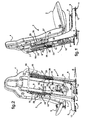
- This seat is mainly composed of a base 1 which supports in hyperstatic maintenance a tub 2 associating a seat 3 and a backrest 4.
- the base 1 is mainly composed of a pair of laterally spaced 5.6 side members which define between them a plan P seat installation on the floor of the unit.
- These rails 5,6 are each extended by respective uprights 7,8 which extend to the back of the backrest 4 to support the tub 2.
- the tub 2 is equipped with a frame 9 composed of beams that extend under the seat 3 and back of the backrest 4.
- these studs 10 are four in number, laterally distributed in pairs, and for each pair are placed in the upper zone and in the lower zone of the backrest 4 with respect to the position of use of the seat.
- the seat is equipped with adjustment means 11 in longitudinal position forwards and / or backwards relative to the orientation of the passenger installed on the seat.
- These adjustment means 11 in longitudinal position comprise in their entirety rails 12 or similar members, which are provided with fasteners to the floor of the apparatus and which slidably receive the longitudinal members 5,6.
- the seat is likely to be equipped with means of maneuver dedicated to the sliding of the longitudinal members 5,6 along the rails 12.
- the seat is equipped with a first geometric compensation mechanism of a deformation of the floor, which are dedicated to the protection of the passenger in case of deformation of the installation plan P of the seat following a deformation of the floor of the apparatus .
- the passenger protection provided by the first mechanism is implemented in a given range of resistance to seat deformation, corresponding to a longitudinal tilting of any spar of the order of 10 ° on either side of the plane. P installation of the seat.
- the studs 10 are axially deformable under the effect of a stress exerted on the seat following a deformation of the longitudinal members 5,6 in the target range.
- the elastic deformation of the studs 10 is limited between two abutment positions, one in the deployed position of the studs 10 and more particularly of the member 14 corresponding to a condition of normal use of the seat, the other in the extreme retracted position of the studs 10 and more particularly the member 14 corresponding to a deformation of at least one of the longitudinal members 5,6 in the target range of plus or minus 10 ° on either side of the seat installation plane P on the apparatus, defined by the initial orientation of the longitudinal members 5,6.
- the studs 10 are each arranged in a pair of members, comprising a tilting pin 13 and an elastically axially deformable elastic sleeve 14 threaded onto the tilting axis 13.
- This elastic sleeve 14 is composed of a set of stacked washers and independently deformable, which are shaped like a plate called "Belleville”.
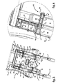
- the tilting axis 13 comprises a ball head 15, which is received in a dedicated housing 16 that includes the uprights 7,8.
- These housings 16 each have an extension along the uprights 7,8 at least sufficient to tolerate an omnidirectional mobility of the tilting axes 13 of the order of plus or minus 5 °.
- the conformation of the ball head 15 of the tilting axes 13 is limited to a tilt capability of the same order.
- Such an omnidirectional mobility range of the tilting axes 13 is sufficient to allow operation of the first mechanism in the target deformation range of the longitudinal members 5, 6.
- the tilting axes 13 comprise shoulders 17, 18 at each of their end faces, to take antagonistic supports against the uprights 7,8 and the frame 9 of the backrest 4.
- One of the shoulders 17 is formed of machining , while the other shoulder 18 is obtained by adding a washer or similar member at the end of the tilting axis 13.
- the elastic sleeve 14 is interposed between one of these shoulders 17, 18, and on the exemplary embodiment illustrated the frame 9 of the folder.
- At least one of the tilting axes 13 pivots in the housing 16 of the upright 7,8 which receives it, with the effect of inducing its elastic deformation in compression and sliding inside a recess 20 that comprises the frame 9 of the backrest 4.
- the tilt axis 13 extends within a socket 21 attached to the inside of this armature 9.
- each of these openings is preferably closed by an attached cover 19, which furthermore constitutes a reinforcing member for the walls bordering the housings 16.
- Such covers 19 make it possible to reinforce the housings 16 to prevent their deformation by spacing their walls, and to prohibit an undesirable escape of the ball head 15 out of the housing 16, which otherwise would be possible to be made possible in case of deformation of the walls of the housing 16.
- the seat is further equipped with a second energy absorption mechanism induced by a sudden change of pace of the flying apparatus during a crash, in order to protect the passenger from this abrupt change of pace, deceleration in particular.
- This second mechanism is more particularly designed to allow relative movement between the tub and the base in the direction of extension of the uprights, while maintaining the hyperstatic support tub 2.
- the respective implementations of the first mechanism and the second mechanism are independent, despite the advantageous pooling of the organs they comprise, studs 10 and housing 16 in particular. More particularly, the second mechanism is capable of being implemented previously, simultaneously or after the implementation of the first mechanism.
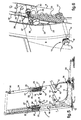
- the second mechanism comprises two sets of members which each associate a fuse 22 for retaining the tub 2 and a plastic support member 23 of the tub 2.
- the fuses 22 are arranged in strips or the like, which comprise a weakening zone 24 capable of being broken from a breaking point. This breaking threshold is predetermined according to an optimum tolerated threshold of stresses exerted on the seat.
- the plastic support members 23 of the tub 2 are generally flat by being arranged along a dedicated amount 7.8, and are stretchable under the effect of the weight of the tub 2 plus the weight of the passenger. Such embodiments of the fuses 22 and / or plastic deformation support members 23 are preferred and illustrated for example, other similar means being capable of being implemented.
- the support member 23 of the tub 2 may consist of a pneumatic cylinder spontaneously closed, provided with a calibrated fuse valve adapted to release the pneumatic cylinder deployed from a certain threshold of resistance.
- the sets of members each associating a fuse 22 and a plastic support member 23, are engaged on a dedicated post 7.8 and on the frame 9 of the backrest 4.
- the taking of the sets of organs 22,23 on the dedicated amount 7.8 is achieved via a pin 26 which is received by the dedicated amount 7.8.
- the catch of the members 22,23 on the frame 9 of the backrest 4 is made by means of the studs 10.
- the receiving housings 16 of the ball head 15 are extended along the corresponding amount 7,8, in preferably being fused from one to the other of these housings 16 into a common housing receiving the two studs 10 assigned to the same side of the tub 2.
- the housings 16 are arranged in the passageway of the studs 10 via ball heads 15 that they comprise.
- the housings 16 are formed by the recess of a slideway from a U-shaped profile or the like.
- the cover 19 consists of a plate, particularly by welding or sealing, against the opening of the slide for its closure and for the reinforcement of the wings of the profile.
- the seat is subjected to energy induced by the sudden deceleration of the device.
- the fuse 22 gives way and the tub 2 is carried by the plastic support members 23.
- the stretching of the plastic support members 23 allows the tub 2 to descend down the uprights 7,8, by a predetermined stroke by the elongation support members 23 according to the weight of the passenger and the energy to be absorbed.
- the bucket 2 is guided in its fall by the studs 10 which run along the housing 16 which receives respectively.
- the hyperstatic maintenance of the tub 2 is preserved and the passenger is protected from the energy absorption provided by the support members 23.
- the seat is advantageously equipped with means for adjusting the height of the bucket position in a normal use situation.
- These provisions are intended to provide comfort to the passenger, especially when he is a pilot of the aircraft.
- These means for adjusting the position of the bucket height include a notching mechanism which implements a set of two notching fingers 27 respectively assigned to a dedicated amount 7.8.
- the notching mechanism is interposed between the base 1 and the bucket 2 by exploiting organs that includes the first mechanism and the second mechanism.
- the latching fingers 27 carry the bucket 2 by means of the studs 10, fuses 22 and pins 26 to which the latching fingers 27 are connected via a corresponding slider 25.
- the sliders 25 are received by the housing 16 for receiving the studs 10 along which they are able to circulate.
- the latching fingers 27 are individually cooperating with a plurality of notches 29 assigned thereto. These pluralities 28 of notches 29 consist of holes which are formed through respective plates 30 reported on one and the other of the uprights 7,8.
- the latching fingers 27 are operable between a spontaneous latching position alternately within one or other of the notches 29 of the plurality 28 which is assigned to them, and a position of disengagement of the latching fingers 27 out of the latches. Notches 29.
- the locking fingers 27 are held in the spontaneous position of notching by means of a dedicated resilient return member 31, and are extractable by actuating means 32 in the disengagement position against the force exercised by the organ 31.
- These means 32 for actuating the latching fingers are pull-type or the like, and for example associate a first traction cable engaged with the latching fingers 27 and a traction handle exerted on the first cable by the passenger for example.
- the means for adjusting the position of the bucket 2 in height further comprise at least one operating member 33 of the tub 2 in the spontaneous position of optimum height.
- This actuator 33 of the bucket 2 is engaged on the latter and is tared to a predetermined force according to the maximum permissible weight of a passenger.
- the actuator 33 of the tub 2 consists of a pneumatic jack housed in the base of the seat delimited between the longitudinal members 5,6.
- This actuator 33 is spontaneously operable at closing and is connected to the bucket 2 via a second pull cable 34, which circulates on a set of return pulleys 35 carried by the base 1 and which is engaged on at least one of the sliders carrying the second mechanism.
- the passenger installs on the seat and maneuvers the locking fingers 27 to their disengaged position.
- the bucket 2 tends to move in height under the effect of the traction spontaneously exerted by the actuator 33 of the bucket 2.
- the bucket 2 releases the fingers of notch 27 which are maneuvered spontaneously by the corresponding elastic member 31 in the notched position to secure the bucket 2 on the base in hyperstatic maintenance.
Landscapes
- Engineering & Computer Science (AREA)
- Aviation & Aerospace Engineering (AREA)
- Seats For Vehicles (AREA)
- Chairs For Special Purposes, Such As Reclining Chairs (AREA)
- Vibration Prevention Devices (AREA)
Applications Claiming Priority (1)
| Application Number | Priority Date | Filing Date | Title |
|---|---|---|---|
| FR0904669A FR2950607B1 (fr) | 2009-09-30 | 2009-09-30 | Siege pour appareils volants motorises, integrant des moyens de protection du passager en cas de crash |
Publications (2)
| Publication Number | Publication Date |
|---|---|
| EP2305561A1 true EP2305561A1 (de) | 2011-04-06 |
| EP2305561B1 EP2305561B1 (de) | 2011-11-16 |
Family
ID=42133781
Family Applications (1)
| Application Number | Title | Priority Date | Filing Date |
|---|---|---|---|
| EP10009473A Active EP2305561B1 (de) | 2009-09-30 | 2010-09-13 | Luftfahrzeugsitz mit Mitteln zum Schützen des Passagiers im Unfallsfall |
Country Status (4)
| Country | Link |
|---|---|
| US (1) | US8408643B2 (de) |
| EP (1) | EP2305561B1 (de) |
| AT (1) | ATE533694T1 (de) |
| FR (1) | FR2950607B1 (de) |
Cited By (2)
| Publication number | Priority date | Publication date | Assignee | Title |
|---|---|---|---|---|
| WO2013174520A1 (de) * | 2012-05-24 | 2013-11-28 | Lufthansa Technik Ag | Flugzeugsitz mit einer sitzbaugruppe |
| FR3013644A1 (fr) * | 2013-11-27 | 2015-05-29 | Eads Sogerma | Siege baquet a cinematique evolutive |
Families Citing this family (38)
| Publication number | Priority date | Publication date | Assignee | Title |
|---|---|---|---|---|
| FR2930520B1 (fr) * | 2008-04-28 | 2010-08-20 | Eurocopter France | Siege anti-ecrasement d'un vehicule |
| US20120273649A1 (en) * | 2009-10-02 | 2012-11-01 | Mobius Protection Systems Ltd. | Shock absorbing device |
| EP2542797B1 (de) | 2010-03-01 | 2017-11-22 | Airbus Helicopters | Verbessertes stromabsorptionselement und vorspannungsflansch dafür |
| US8550553B1 (en) | 2010-10-19 | 2013-10-08 | Armorworks Enterprises LLC | Side mounted energy attenuating vehicle seat |
| EP3971027B1 (de) * | 2011-04-05 | 2025-12-31 | Safran Seats | Verstellbarer sitz |
| US8888179B1 (en) * | 2012-02-28 | 2014-11-18 | Armorworks Enterprises LLC | Tube-expansion energy attenuating system |
| FR2991667B1 (fr) * | 2012-06-06 | 2015-05-29 | Eads Sogerma | Siege d'aeronef a structure monopoutre et aeronef comportant un tel siege |
| US20150321763A1 (en) * | 2012-11-21 | 2015-11-12 | Zodiac Seats France | Crashworthy bench |
| FR3001418B1 (fr) | 2013-01-29 | 2016-06-10 | Eurocopter France | Siege pour aeronef motorise muni d'un pietement comportant au plus trois points d'ancrage au plancher de l'aeronef |
| FR3006668B1 (fr) * | 2013-06-10 | 2015-06-26 | Eurocopter France | Siege anti crash et aeronef |
| US9221361B1 (en) * | 2013-11-27 | 2015-12-29 | Armorworks Enterprises LLC | Spring assisted energy attenuating seating system |
| FR3014042B1 (fr) * | 2013-11-29 | 2017-03-17 | Eads Sogerma | Siege passager a structure baquet et position ajustable |
| FR3016862B1 (fr) | 2014-01-24 | 2016-01-22 | Airbus Helicopters | Banquette pour aeronef comportant des baquets montes individuellement basculants vers le bas et a l'arriere de la banquette en cas de forte deceleration de l'aeronef |
| US9481466B2 (en) | 2014-06-26 | 2016-11-01 | Itt Manufacturing Enterprises Llc | Powered seat and control thereof |
| FR3026090B1 (fr) | 2014-09-23 | 2017-05-19 | Airbus Helicopters | Banquette pour aeronef organisee pour l'accueil d'un nombre variable de passagers |
| US9352671B1 (en) | 2015-01-29 | 2016-05-31 | Autoliv Asp, Inc. | Vehicle seat displacement systems and related methods and apparatus |
| GB201503829D0 (en) * | 2015-03-06 | 2015-04-22 | Rebel Aero Ltd | Support arrangement for an aircraft seat |
| IL245081A0 (en) | 2015-04-13 | 2016-08-31 | Survivability Solutions Llc | Support for car seat assembly and security systems |
| US9745066B2 (en) * | 2015-09-03 | 2017-08-29 | Ami Industries, Inc. | Adjustable seat assembly |
| FR3048388B1 (fr) * | 2016-03-01 | 2019-05-10 | Airbus Helicopters | Siege d'aeronef tolerant aux deformations du plancher |
| DE102016213085A1 (de) * | 2016-07-18 | 2018-01-18 | Lufthansa Technik Ag | Flugzeugsitz mit einer Sitzbaugruppe |
| DE102016217405B3 (de) * | 2016-09-13 | 2018-01-18 | Adient Luxembourg Holding S.à.r.l. | Energieabsorber für einen fahrzeugsitz sowie lineareinsteller für einen fahrzeugsitz mit einem energieabsorber |
| KR20180043647A (ko) * | 2016-10-20 | 2018-04-30 | 주식회사 에이스카이 | 비상 탈출 훈련 장치 및 방법 |
| US10479227B2 (en) * | 2017-07-10 | 2019-11-19 | GM Global Technology Operations LLC | Systems and methods for controlling automotive seat adjustments using electromagnetic rail technology |
| WO2020008237A1 (en) | 2018-07-04 | 2020-01-09 | Bosch Car Multimedia Portugal, S.A. | System carrier for instrument clusters |
| DE102018119846A1 (de) | 2018-08-15 | 2020-02-20 | Recaro Aircraft Seating Gmbh & Co. Kg | Flugzeugsitzbefestigungsvorrichtung |
| SE543787C2 (en) * | 2019-02-28 | 2021-07-20 | Mim Construction Ab | Security arrangement for a load carrying assembly |
| EP4053017B1 (de) | 2021-03-01 | 2024-07-31 | Autoflug GmbH | Energieabsorptionsvorrichtung für einen sitz eines fahrzeugs und sitzsystem mit einer solchen energieabsorptionsvorrichtung |
| US11794904B2 (en) | 2021-11-09 | 2023-10-24 | Ami Industries, Inc. | Compact rotorcraft seating assembly with non-linear bucket guide channels |
| CN116118583B (zh) * | 2021-11-12 | 2025-05-23 | 明门瑞士股份有限公司 | 儿童安全座椅 |
| US11975840B2 (en) * | 2022-03-31 | 2024-05-07 | B/E Aerospace, Inc. | Fuse link head impact criteria mitigating device |
| US11945590B1 (en) | 2022-09-08 | 2024-04-02 | Ami Industries, Inc. | Aircraft seat with energy attenuating metering plate |
| US12049321B2 (en) * | 2022-09-08 | 2024-07-30 | Ami Industries, Inc. | Aircraft bulkhead-mounted pilot seat with horizontal and vertical adjustment |
| US12122521B2 (en) | 2022-10-14 | 2024-10-22 | Ami Industries, Inc. | Offset helicopter pilot seat with centered vertical motion system |
| US12252253B2 (en) | 2022-10-14 | 2025-03-18 | Ami Industries, Inc. | Aircraft seat with nested energy attenuation guide system |
| US12195187B2 (en) | 2022-10-14 | 2025-01-14 | Ami Industries, Inc. | Offset helicopter pilot seat with singular energy absorber |
| FR3147250A1 (fr) | 2023-04-03 | 2024-10-04 | Helicopteres Guimbal | Agencement de siège anti-crash destiné à un aéronef, et aéronef à voilure tournante |
| US12552539B2 (en) | 2023-11-15 | 2026-02-17 | Ami Industries, Inc. | Method for automatic seat pan tilt |
Citations (6)
| Publication number | Priority date | Publication date | Assignee | Title |
|---|---|---|---|---|
| FR2495101A1 (fr) * | 1980-12-01 | 1982-06-04 | Socea | Siege de securite anticrash notamment pour aeronef |
| FR2683191A1 (fr) | 1991-10-31 | 1993-05-07 | Israel Aircraft Ind Ltd | Systeme d'attenuation d'energie pour un siege de vehicule. |
| US5273240A (en) * | 1991-05-02 | 1993-12-28 | Baruch Sharon | Impact absorption system, particularly for aircraft seats |
| DE4312343A1 (de) | 1993-04-15 | 1994-10-27 | Eurocopter Deutschland | Überlastabsorber in Faserverbundbauweise |
| EP0659642A1 (de) * | 1993-12-22 | 1995-06-28 | AEROSPATIALE Société Nationale Industrielle | Flugzeugsitz insbesondere für einen Drehflügler mit abhängig vom Gewicht des Fluggastes selbsttätig regelbarer energieabsorbierender Vorrichtung |
| EP0814020A2 (de) | 1996-06-19 | 1997-12-29 | Martin-Baker Aircraft Co. Ltd. | Unfallsitz |
Family Cites Families (4)
| Publication number | Priority date | Publication date | Assignee | Title |
|---|---|---|---|---|
| US3059966A (en) * | 1959-11-04 | 1962-10-23 | Aerotec Ind Inc | Energy-absorbing means |
| US3985388A (en) * | 1975-08-11 | 1976-10-12 | Uop Inc. | Vertically adjustable seat with energy absorbing means |
| US4358154A (en) * | 1980-12-05 | 1982-11-09 | Boeing Vertol Company | Vehicle crashworthy seat |
| DE3271784D1 (en) * | 1981-11-02 | 1986-07-24 | Eng Patents & Equip | Energy absorbing seat arrangement |
-
2009
- 2009-09-30 FR FR0904669A patent/FR2950607B1/fr not_active Expired - Fee Related
-
2010
- 2010-09-13 EP EP10009473A patent/EP2305561B1/de active Active
- 2010-09-13 AT AT10009473T patent/ATE533694T1/de active
- 2010-09-29 US US12/893,014 patent/US8408643B2/en not_active Expired - Fee Related
Patent Citations (6)
| Publication number | Priority date | Publication date | Assignee | Title |
|---|---|---|---|---|
| FR2495101A1 (fr) * | 1980-12-01 | 1982-06-04 | Socea | Siege de securite anticrash notamment pour aeronef |
| US5273240A (en) * | 1991-05-02 | 1993-12-28 | Baruch Sharon | Impact absorption system, particularly for aircraft seats |
| FR2683191A1 (fr) | 1991-10-31 | 1993-05-07 | Israel Aircraft Ind Ltd | Systeme d'attenuation d'energie pour un siege de vehicule. |
| DE4312343A1 (de) | 1993-04-15 | 1994-10-27 | Eurocopter Deutschland | Überlastabsorber in Faserverbundbauweise |
| EP0659642A1 (de) * | 1993-12-22 | 1995-06-28 | AEROSPATIALE Société Nationale Industrielle | Flugzeugsitz insbesondere für einen Drehflügler mit abhängig vom Gewicht des Fluggastes selbsttätig regelbarer energieabsorbierender Vorrichtung |
| EP0814020A2 (de) | 1996-06-19 | 1997-12-29 | Martin-Baker Aircraft Co. Ltd. | Unfallsitz |
Cited By (5)
| Publication number | Priority date | Publication date | Assignee | Title |
|---|---|---|---|---|
| WO2013174520A1 (de) * | 2012-05-24 | 2013-11-28 | Lufthansa Technik Ag | Flugzeugsitz mit einer sitzbaugruppe |
| US9511865B2 (en) | 2012-05-24 | 2016-12-06 | Lufthansa Technik Ag | Aircraft seat comprising a seat assembly |
| FR3013644A1 (fr) * | 2013-11-27 | 2015-05-29 | Eads Sogerma | Siege baquet a cinematique evolutive |
| EP2878537A1 (de) | 2013-11-27 | 2015-06-03 | Stelia Aerospace | Schalensitz mit erweiterbarer Kinematik |
| US9421886B2 (en) | 2013-11-27 | 2016-08-23 | Stelia Aerospace | Bucket seat with changing kinematics |
Also Published As
| Publication number | Publication date |
|---|---|
| EP2305561B1 (de) | 2011-11-16 |
| FR2950607A1 (fr) | 2011-04-01 |
| US8408643B2 (en) | 2013-04-02 |
| ATE533694T1 (de) | 2011-12-15 |
| US20110079681A1 (en) | 2011-04-07 |
| FR2950607B1 (fr) | 2011-08-26 |
Similar Documents
| Publication | Publication Date | Title |
|---|---|---|
| EP2305561B1 (de) | Luftfahrzeugsitz mit Mitteln zum Schützen des Passagiers im Unfallsfall | |
| EP3341291B1 (de) | Tabletttischarme mit aufhebung des drehanschlags | |
| EP2978633B1 (de) | Fahrzeugsitz ausgestattet mit einem klappbaren element, wie z.b. einem klapptisch | |
| EP2127941A1 (de) | Stoßdämpfungsvorrichtung und mit dieser Vorrichtung ausgestatteter Sitz | |
| EP3374264B1 (de) | Flugzeugsitz für crew | |
| WO1982001854A1 (en) | Vehicle crashworthy seat | |
| EP3269643B1 (de) | Klappsitz und mit diesem klappsitz ausgestattetes fahrzeug | |
| EP3368417B1 (de) | Anordnung mit einem passagiersitz und einem sitz für bordpersonal | |
| EP3074271B1 (de) | System mit einer schwenkbaren armlehne und einem pendelelement | |
| EP2161159B1 (de) | Sicherheitsvorrichtung für einen Kindersitz in einem Fahrzeug | |
| DE102014205456A1 (de) | Kopfstütze für einen Fahrzeugsitz | |
| DE102014205457A1 (de) | Kopfstütze für einen Fahrzeugsitz | |
| EP0747256B1 (de) | Drehbarer Sicherheitsitz | |
| FR3016862A1 (fr) | Banquette pour aeronef comportant des baquets montes individuellement basculants vers le bas et a l'arriere de la banquette en cas de forte deceleration de l'aeronef | |
| EP3781433B1 (de) | System zur verriegelung eines sitzrückes durch trägheit | |
| EP0592273A2 (de) | Fahrzeugsitz mit einer teilbeweglichen Rückenlehne | |
| FR3018247A1 (fr) | Dispositif d'ancrage partiellement mobile pour une ceinture de securite a trois points de vehicule | |
| EP2808199A1 (de) | Klappsitz für Fahrzeugkabine, der eine Vielzahl von Gelenkachsen umfasst | |
| EP0945302A1 (de) | Vorrichtung zum Auflösen der Masse, mit solcher Vorrichtung ausgerüstete Sitzstruktur, Sitz und Fahrzeug | |
| EP2616269B1 (de) | Sitz für ein kraftfahrzeug | |
| EP3585644B1 (de) | Fahrzeugsitz mit mindestens einem dämpfungsmittel | |
| FR3062608A1 (fr) | Dispositif de verrouillage reversible a palonnier de la position longitudinale d'un siege et ensemble de siege le comprenant | |
| EP4347399B1 (de) | Sitzschale, insbesondere für einen flugzeugsitz, mit einem rohr zur absorption kinetischer energie | |
| FR2645809A1 (fr) | Dispositif de securite pour les passagers arriere d'un vehicule | |
| EP3172081B1 (de) | Vorrichtung zum anheben eines fahrzeugsitzes, mit einem abstandshalterteil zur übertragung von rotation und zur übertragung von kraft |
Legal Events
| Date | Code | Title | Description |
|---|---|---|---|
| PUAI | Public reference made under article 153(3) epc to a published international application that has entered the european phase |
Free format text: ORIGINAL CODE: 0009012 |
|
| AK | Designated contracting states |
Kind code of ref document: A1 Designated state(s): AL AT BE BG CH CY CZ DE DK EE ES FI FR GB GR HR HU IE IS IT LI LT LU LV MC MK MT NL NO PL PT RO SE SI SK SM TR |
|
| AX | Request for extension of the european patent |
Extension state: BA ME RS |
|
| 17P | Request for examination filed |
Effective date: 20110426 |
|
| RIC1 | Information provided on ipc code assigned before grant |
Ipc: B64D 25/04 20060101ALI20110530BHEP Ipc: B64D 11/06 20060101AFI20110530BHEP |
|
| GRAP | Despatch of communication of intention to grant a patent |
Free format text: ORIGINAL CODE: EPIDOSNIGR1 |
|
| GRAS | Grant fee paid |
Free format text: ORIGINAL CODE: EPIDOSNIGR3 |
|
| GRAA | (expected) grant |
Free format text: ORIGINAL CODE: 0009210 |
|
| AK | Designated contracting states |
Kind code of ref document: B1 Designated state(s): AL AT BE BG CH CY CZ DE DK EE ES FI FR GB GR HR HU IE IS IT LI LT LU LV MC MK MT NL NO PL PT RO SE SI SK SM TR |
|
| REG | Reference to a national code |
Ref country code: GB Ref legal event code: FG4D Free format text: NOT ENGLISH |
|
| REG | Reference to a national code |
Ref country code: CH Ref legal event code: EP |
|
| REG | Reference to a national code |
Ref country code: IE Ref legal event code: FG4D Free format text: LANGUAGE OF EP DOCUMENT: FRENCH |
|
| REG | Reference to a national code |
Ref country code: DE Ref legal event code: R096 Ref document number: 602010000398 Country of ref document: DE Effective date: 20120126 |
|
| REG | Reference to a national code |
Ref country code: NL Ref legal event code: VDEP Effective date: 20111116 |
|
| LTIE | Lt: invalidation of european patent or patent extension |
Effective date: 20111116 |
|
| PG25 | Lapsed in a contracting state [announced via postgrant information from national office to epo] |
Ref country code: IS Free format text: LAPSE BECAUSE OF FAILURE TO SUBMIT A TRANSLATION OF THE DESCRIPTION OR TO PAY THE FEE WITHIN THE PRESCRIBED TIME-LIMIT Effective date: 20120316 Ref country code: LT Free format text: LAPSE BECAUSE OF FAILURE TO SUBMIT A TRANSLATION OF THE DESCRIPTION OR TO PAY THE FEE WITHIN THE PRESCRIBED TIME-LIMIT Effective date: 20111116 Ref country code: NO Free format text: LAPSE BECAUSE OF FAILURE TO SUBMIT A TRANSLATION OF THE DESCRIPTION OR TO PAY THE FEE WITHIN THE PRESCRIBED TIME-LIMIT Effective date: 20120216 |
|
| PG25 | Lapsed in a contracting state [announced via postgrant information from national office to epo] |
Ref country code: PT Free format text: LAPSE BECAUSE OF FAILURE TO SUBMIT A TRANSLATION OF THE DESCRIPTION OR TO PAY THE FEE WITHIN THE PRESCRIBED TIME-LIMIT Effective date: 20120316 Ref country code: PL Free format text: LAPSE BECAUSE OF FAILURE TO SUBMIT A TRANSLATION OF THE DESCRIPTION OR TO PAY THE FEE WITHIN THE PRESCRIBED TIME-LIMIT Effective date: 20111116 Ref country code: GR Free format text: LAPSE BECAUSE OF FAILURE TO SUBMIT A TRANSLATION OF THE DESCRIPTION OR TO PAY THE FEE WITHIN THE PRESCRIBED TIME-LIMIT Effective date: 20120217 Ref country code: NL Free format text: LAPSE BECAUSE OF FAILURE TO SUBMIT A TRANSLATION OF THE DESCRIPTION OR TO PAY THE FEE WITHIN THE PRESCRIBED TIME-LIMIT Effective date: 20111116 Ref country code: SI Free format text: LAPSE BECAUSE OF FAILURE TO SUBMIT A TRANSLATION OF THE DESCRIPTION OR TO PAY THE FEE WITHIN THE PRESCRIBED TIME-LIMIT Effective date: 20111116 Ref country code: SE Free format text: LAPSE BECAUSE OF FAILURE TO SUBMIT A TRANSLATION OF THE DESCRIPTION OR TO PAY THE FEE WITHIN THE PRESCRIBED TIME-LIMIT Effective date: 20111116 Ref country code: LV Free format text: LAPSE BECAUSE OF FAILURE TO SUBMIT A TRANSLATION OF THE DESCRIPTION OR TO PAY THE FEE WITHIN THE PRESCRIBED TIME-LIMIT Effective date: 20111116 Ref country code: HR Free format text: LAPSE BECAUSE OF FAILURE TO SUBMIT A TRANSLATION OF THE DESCRIPTION OR TO PAY THE FEE WITHIN THE PRESCRIBED TIME-LIMIT Effective date: 20111116 |
|
| REG | Reference to a national code |
Ref country code: IE Ref legal event code: FD4D |
|
| PG25 | Lapsed in a contracting state [announced via postgrant information from national office to epo] |
Ref country code: CY Free format text: LAPSE BECAUSE OF FAILURE TO SUBMIT A TRANSLATION OF THE DESCRIPTION OR TO PAY THE FEE WITHIN THE PRESCRIBED TIME-LIMIT Effective date: 20111116 |
|
| PG25 | Lapsed in a contracting state [announced via postgrant information from national office to epo] |
Ref country code: SK Free format text: LAPSE BECAUSE OF FAILURE TO SUBMIT A TRANSLATION OF THE DESCRIPTION OR TO PAY THE FEE WITHIN THE PRESCRIBED TIME-LIMIT Effective date: 20111116 Ref country code: BG Free format text: LAPSE BECAUSE OF FAILURE TO SUBMIT A TRANSLATION OF THE DESCRIPTION OR TO PAY THE FEE WITHIN THE PRESCRIBED TIME-LIMIT Effective date: 20120216 Ref country code: DK Free format text: LAPSE BECAUSE OF FAILURE TO SUBMIT A TRANSLATION OF THE DESCRIPTION OR TO PAY THE FEE WITHIN THE PRESCRIBED TIME-LIMIT Effective date: 20111116 Ref country code: IE Free format text: LAPSE BECAUSE OF FAILURE TO SUBMIT A TRANSLATION OF THE DESCRIPTION OR TO PAY THE FEE WITHIN THE PRESCRIBED TIME-LIMIT Effective date: 20111116 Ref country code: CZ Free format text: LAPSE BECAUSE OF FAILURE TO SUBMIT A TRANSLATION OF THE DESCRIPTION OR TO PAY THE FEE WITHIN THE PRESCRIBED TIME-LIMIT Effective date: 20111116 Ref country code: EE Free format text: LAPSE BECAUSE OF FAILURE TO SUBMIT A TRANSLATION OF THE DESCRIPTION OR TO PAY THE FEE WITHIN THE PRESCRIBED TIME-LIMIT Effective date: 20111116 |
|
| PG25 | Lapsed in a contracting state [announced via postgrant information from national office to epo] |
Ref country code: RO Free format text: LAPSE BECAUSE OF FAILURE TO SUBMIT A TRANSLATION OF THE DESCRIPTION OR TO PAY THE FEE WITHIN THE PRESCRIBED TIME-LIMIT Effective date: 20111116 |
|
| REG | Reference to a national code |
Ref country code: AT Ref legal event code: MK05 Ref document number: 533694 Country of ref document: AT Kind code of ref document: T Effective date: 20111116 |
|
| PLBE | No opposition filed within time limit |
Free format text: ORIGINAL CODE: 0009261 |
|
| STAA | Information on the status of an ep patent application or granted ep patent |
Free format text: STATUS: NO OPPOSITION FILED WITHIN TIME LIMIT |
|
| 26N | No opposition filed |
Effective date: 20120817 |
|
| REG | Reference to a national code |
Ref country code: DE Ref legal event code: R097 Ref document number: 602010000398 Country of ref document: DE Effective date: 20120817 |
|
| PG25 | Lapsed in a contracting state [announced via postgrant information from national office to epo] |
Ref country code: AT Free format text: LAPSE BECAUSE OF FAILURE TO SUBMIT A TRANSLATION OF THE DESCRIPTION OR TO PAY THE FEE WITHIN THE PRESCRIBED TIME-LIMIT Effective date: 20111116 |
|
| BERE | Be: lapsed |
Owner name: EUROCOPTER Effective date: 20120930 |
|
| PG25 | Lapsed in a contracting state [announced via postgrant information from national office to epo] |
Ref country code: ES Free format text: LAPSE BECAUSE OF FAILURE TO SUBMIT A TRANSLATION OF THE DESCRIPTION OR TO PAY THE FEE WITHIN THE PRESCRIBED TIME-LIMIT Effective date: 20120227 Ref country code: MC Free format text: LAPSE BECAUSE OF NON-PAYMENT OF DUE FEES Effective date: 20120930 |
|
| PG25 | Lapsed in a contracting state [announced via postgrant information from national office to epo] |
Ref country code: FI Free format text: LAPSE BECAUSE OF FAILURE TO SUBMIT A TRANSLATION OF THE DESCRIPTION OR TO PAY THE FEE WITHIN THE PRESCRIBED TIME-LIMIT Effective date: 20111116 |
|
| PG25 | Lapsed in a contracting state [announced via postgrant information from national office to epo] |
Ref country code: BE Free format text: LAPSE BECAUSE OF NON-PAYMENT OF DUE FEES Effective date: 20120930 |
|
| PG25 | Lapsed in a contracting state [announced via postgrant information from national office to epo] |
Ref country code: MT Free format text: LAPSE BECAUSE OF FAILURE TO SUBMIT A TRANSLATION OF THE DESCRIPTION OR TO PAY THE FEE WITHIN THE PRESCRIBED TIME-LIMIT Effective date: 20111116 Ref country code: AL Free format text: LAPSE BECAUSE OF FAILURE TO SUBMIT A TRANSLATION OF THE DESCRIPTION OR TO PAY THE FEE WITHIN THE PRESCRIBED TIME-LIMIT Effective date: 20111116 |
|
| PG25 | Lapsed in a contracting state [announced via postgrant information from national office to epo] |
Ref country code: TR Free format text: LAPSE BECAUSE OF FAILURE TO SUBMIT A TRANSLATION OF THE DESCRIPTION OR TO PAY THE FEE WITHIN THE PRESCRIBED TIME-LIMIT Effective date: 20111116 |
|
| PG25 | Lapsed in a contracting state [announced via postgrant information from national office to epo] |
Ref country code: SM Free format text: LAPSE BECAUSE OF FAILURE TO SUBMIT A TRANSLATION OF THE DESCRIPTION OR TO PAY THE FEE WITHIN THE PRESCRIBED TIME-LIMIT Effective date: 20111116 Ref country code: LU Free format text: LAPSE BECAUSE OF NON-PAYMENT OF DUE FEES Effective date: 20120913 |
|
| REG | Reference to a national code |
Ref country code: FR Ref legal event code: CD Owner name: AIRBUS HELICOPTERS, FR Effective date: 20140602 |
|
| PG25 | Lapsed in a contracting state [announced via postgrant information from national office to epo] |
Ref country code: HU Free format text: LAPSE BECAUSE OF FAILURE TO SUBMIT A TRANSLATION OF THE DESCRIPTION OR TO PAY THE FEE WITHIN THE PRESCRIBED TIME-LIMIT Effective date: 20100913 |
|
| REG | Reference to a national code |
Ref country code: DE Ref legal event code: R082 Ref document number: 602010000398 Country of ref document: DE Representative=s name: GPI & ASSOCIES, FR |
|
| REG | Reference to a national code |
Ref country code: CH Ref legal event code: PL |
|
| REG | Reference to a national code |
Ref country code: DE Ref legal event code: R082 Ref document number: 602010000398 Country of ref document: DE Representative=s name: GPI & ASSOCIES, FR Ref country code: DE Ref legal event code: R081 Ref document number: 602010000398 Country of ref document: DE Owner name: AIRBUS HELICOPTERS, FR Free format text: FORMER OWNER: EUROCOPTER, MARIGNANE, FR |
|
| PG25 | Lapsed in a contracting state [announced via postgrant information from national office to epo] |
Ref country code: CH Free format text: LAPSE BECAUSE OF NON-PAYMENT OF DUE FEES Effective date: 20140930 Ref country code: MK Free format text: LAPSE BECAUSE OF FAILURE TO SUBMIT A TRANSLATION OF THE DESCRIPTION OR TO PAY THE FEE WITHIN THE PRESCRIBED TIME-LIMIT Effective date: 20111116 Ref country code: LI Free format text: LAPSE BECAUSE OF NON-PAYMENT OF DUE FEES Effective date: 20140930 |
|
| REG | Reference to a national code |
Ref country code: FR Ref legal event code: PLFP Year of fee payment: 7 |
|
| REG | Reference to a national code |
Ref country code: FR Ref legal event code: PLFP Year of fee payment: 8 |
|
| REG | Reference to a national code |
Ref country code: FR Ref legal event code: PLFP Year of fee payment: 9 |
|
| PGFP | Annual fee paid to national office [announced via postgrant information from national office to epo] |
Ref country code: GB Payment date: 20220920 Year of fee payment: 13 |
|
| PGFP | Annual fee paid to national office [announced via postgrant information from national office to epo] |
Ref country code: IT Payment date: 20220926 Year of fee payment: 13 |
|
| P01 | Opt-out of the competence of the unified patent court (upc) registered |
Effective date: 20230530 |
|
| GBPC | Gb: european patent ceased through non-payment of renewal fee |
Effective date: 20230913 |
|
| PG25 | Lapsed in a contracting state [announced via postgrant information from national office to epo] |
Ref country code: GB Free format text: LAPSE BECAUSE OF NON-PAYMENT OF DUE FEES Effective date: 20230913 |
|
| PG25 | Lapsed in a contracting state [announced via postgrant information from national office to epo] |
Ref country code: GB Free format text: LAPSE BECAUSE OF NON-PAYMENT OF DUE FEES Effective date: 20230913 |
|
| PG25 | Lapsed in a contracting state [announced via postgrant information from national office to epo] |
Ref country code: IT Free format text: LAPSE BECAUSE OF NON-PAYMENT OF DUE FEES Effective date: 20230913 |
|
| PG25 | Lapsed in a contracting state [announced via postgrant information from national office to epo] |
Ref country code: IT Free format text: LAPSE BECAUSE OF NON-PAYMENT OF DUE FEES Effective date: 20230913 |
|
| PGFP | Annual fee paid to national office [announced via postgrant information from national office to epo] |
Ref country code: DE Payment date: 20250919 Year of fee payment: 16 |
|
| PGFP | Annual fee paid to national office [announced via postgrant information from national office to epo] |
Ref country code: FR Payment date: 20250919 Year of fee payment: 16 |