EP2305594B1 - Lernvorrichtung und lernverfahren in einer produktförderungsanlage - Google Patents
Lernvorrichtung und lernverfahren in einer produktförderungsanlage Download PDFInfo
- Publication number
- EP2305594B1 EP2305594B1 EP09800310.6A EP09800310A EP2305594B1 EP 2305594 B1 EP2305594 B1 EP 2305594B1 EP 09800310 A EP09800310 A EP 09800310A EP 2305594 B1 EP2305594 B1 EP 2305594B1
- Authority
- EP
- European Patent Office
- Prior art keywords
- deviation amount
- grip portion
- lowering
- vehicle
- learn
- Prior art date
- Legal status (The legal status is an assumption and is not a legal conclusion. Google has not performed a legal analysis and makes no representation as to the accuracy of the status listed.)
- Active
Links
Images


Classifications
-
- B—PERFORMING OPERATIONS; TRANSPORTING
- B66—HOISTING; LIFTING; HAULING
- B66C—CRANES; LOAD-ENGAGING ELEMENTS OR DEVICES FOR CRANES, CAPSTANS, WINCHES, OR TACKLES
- B66C13/00—Other constructional features or details
- B66C13/18—Control systems or devices
- B66C13/22—Control systems or devices for electric drives
-
- B—PERFORMING OPERATIONS; TRANSPORTING
- B66—HOISTING; LIFTING; HAULING
- B66C—CRANES; LOAD-ENGAGING ELEMENTS OR DEVICES FOR CRANES, CAPSTANS, WINCHES, OR TACKLES
- B66C1/00—Load-engaging elements or devices attached to lifting or lowering gear of cranes or adapted for connection therewith for transmitting lifting forces to articles or groups of articles
- B66C1/10—Load-engaging elements or devices attached to lifting or lowering gear of cranes or adapted for connection therewith for transmitting lifting forces to articles or groups of articles by mechanical means
- B66C1/22—Rigid members, e.g. L-shaped members, with parts engaging the under surface of the loads; Crane hooks
- B66C1/28—Duplicate, e.g. pivoted, members engaging the loads from two sides
-
- B—PERFORMING OPERATIONS; TRANSPORTING
- B66—HOISTING; LIFTING; HAULING
- B66C—CRANES; LOAD-ENGAGING ELEMENTS OR DEVICES FOR CRANES, CAPSTANS, WINCHES, OR TACKLES
- B66C13/00—Other constructional features or details
- B66C13/18—Control systems or devices
- B66C13/46—Position indicators for suspended loads or for crane elements
-
- B—PERFORMING OPERATIONS; TRANSPORTING
- B66—HOISTING; LIFTING; HAULING
- B66C—CRANES; LOAD-ENGAGING ELEMENTS OR DEVICES FOR CRANES, CAPSTANS, WINCHES, OR TACKLES
- B66C13/00—Other constructional features or details
- B66C13/18—Control systems or devices
- B66C13/48—Automatic control of crane drives for producing a single or repeated working cycle; Program control
-
- H—ELECTRICITY
- H10—SEMICONDUCTOR DEVICES; ELECTRIC SOLID-STATE DEVICES NOT OTHERWISE PROVIDED FOR
- H10P—GENERIC PROCESSES OR APPARATUS FOR THE MANUFACTURE OR TREATMENT OF DEVICES COVERED BY CLASS H10
- H10P72/00—Handling or holding of wafers, substrates or devices during manufacture or treatment thereof
- H10P72/30—Handling or holding of wafers, substrates or devices during manufacture or treatment thereof for conveying, e.g. between different workstations
- H10P72/32—Handling or holding of wafers, substrates or devices during manufacture or treatment thereof for conveying, e.g. between different workstations between different workstations
- H10P72/3221—Overhead conveying
-
- H—ELECTRICITY
- H10—SEMICONDUCTOR DEVICES; ELECTRIC SOLID-STATE DEVICES NOT OTHERWISE PROVIDED FOR
- H10P—GENERIC PROCESSES OR APPARATUS FOR THE MANUFACTURE OR TREATMENT OF DEVICES COVERED BY CLASS H10
- H10P72/00—Handling or holding of wafers, substrates or devices during manufacture or treatment thereof
- H10P72/30—Handling or holding of wafers, substrates or devices during manufacture or treatment thereof for conveying, e.g. between different workstations
- H10P72/32—Handling or holding of wafers, substrates or devices during manufacture or treatment thereof for conveying, e.g. between different workstations between different workstations
- H10P72/3222—Loading to or unloading from a conveyor
-
- H—ELECTRICITY
- H10—SEMICONDUCTOR DEVICES; ELECTRIC SOLID-STATE DEVICES NOT OTHERWISE PROVIDED FOR
- H10P—GENERIC PROCESSES OR APPARATUS FOR THE MANUFACTURE OR TREATMENT OF DEVICES COVERED BY CLASS H10
- H10P72/00—Handling or holding of wafers, substrates or devices during manufacture or treatment thereof
- H10P72/50—Handling or holding of wafers, substrates or devices during manufacture or treatment thereof for positioning, orientation or alignment
- H10P72/53—Handling or holding of wafers, substrates or devices during manufacture or treatment thereof for positioning, orientation or alignment using optical controlling means
-
- H—ELECTRICITY
- H10—SEMICONDUCTOR DEVICES; ELECTRIC SOLID-STATE DEVICES NOT OTHERWISE PROVIDED FOR
- H10P—GENERIC PROCESSES OR APPARATUS FOR THE MANUFACTURE OR TREATMENT OF DEVICES COVERED BY CLASS H10
- H10P72/00—Handling or holding of wafers, substrates or devices during manufacture or treatment thereof
- H10P72/70—Handling or holding of wafers, substrates or devices during manufacture or treatment thereof for supporting or gripping
- H10P72/76—Handling or holding of wafers, substrates or devices during manufacture or treatment thereof for supporting or gripping using mechanical means, e.g. clamps or pinches
- H10P72/7602—Handling or holding of wafers, substrates or devices during manufacture or treatment thereof for supporting or gripping using mechanical means, e.g. clamps or pinches the wafers being placed on a robot blade or gripped by a gripper for conveyance
Definitions
- the present invention relates to a learning device and a learning method for an article transport facility comprising a vehicle configured to move along a travel path, and having a grip portion for gripping an article with the article suspended therefrom, vertical movement means for raising and lowering the grip portion with respect to the vehicle, position adjustment means for adjusting a position of the grip portion horizontally with respect to the vehicle, wherein articles are transferred to and from a transfer support portion located below the travel path by raising and lowering the grip portion with the vehicle stopped at a target stop position in the travel path.
- a plurality of transfer support portions are provided along the travel path and the facilities are configured to transport articles among the plurality of the transfer support portions.
- the grip portion is raised and lowered with respect to the transfer support portion with the vehicle stopped at a target stop position in a travel path.
- the grip portion may become horizontally displaced from the position it is expected to be, due, for example, to inaccuracies in the installation position of the transfer support portion or due to the swaying motion during the raising and lowering of the grip portion.
- the learning device and the learning method for the article transport facility in accordance with the present invention are provided to learn such position adjustment amount. And when actually transferring articles to or from each transfer support portion, the position of the grip portion in the horizontal direction is adjusted using the learned position adjustment amount.
- a learning device in a conventional article transport facility is provided with a first learn assist member that can be attached to a transfer support portion and that has a detection mark for indicating the position corresponding to the target transfer reference position in the horizontal direction for the transfer support portion with the first learn assist member attached to the transfer support portion, a second learn assist member that the grip portion can grip and that has an imaging means that can capture an image of the area below the grip portion to capture an image of the detection mark with the second learn assist member gripped by the grip portion, and a learning control means -- that controls moving operations of the vehicle, vertical movement operations of the vertical movement means, and imaging operations of the imaging means-- for learning the amount of position adjustment in the horizontal direction when raising and lowering the grip portion with respect to the transfer support portion with the vehicle stopped at the target stop position for the transfer support portion.
- the learning control means moves the vehicle to the target stop position with respect to the transfer support portion, and performs a positioning process in which the grip portion is raised and lowered such that the second learn assist member gripped by the grip portion, with the second learn assist member adjusted to the standard adjustment position, is located at a target height with respect to the first learn assist member attached to the transfer support portion.
- the standard adjustment position is, for example, a position in which the center of the grip portion coincides with the center of the vehicle in the lateral direction of the vehicle, and in which the lateral direction and the fore and aft direction of the grip portion coincide with the lateral direction and the fore and aft direction of the vehicle in the angular direction about a vertical axis.
- the learning control means is configured to perform an image capturing process in which the imaging means is caused to capture an image of the detection mark, and to perform a deviation amount calculating process in which a reference position deviation amount in the horizontal direction between the imaging reference position set in the center of the field of view of the image and the detection mark is derived based on the image information captured in the image capturing process to calculate the position adjustment amount from the derived reference position deviation amount.
- an image capturing process in which the imaging means is caused to capture an image of the detection mark
- a deviation amount calculating process in which a reference position deviation amount in the horizontal direction between the imaging reference position set in the center of the field of view of the image and the detection mark is derived based on the image information captured in the image capturing process to calculate the position adjustment amount from the derived reference position deviation amount.
- Patent Document 1 Japanese Patent Application Publication No. 2003-192269
- the learning control means derives the reference position deviation amount in the horizontal direction between the imaging reference position and the detection mark based on the image information in the deviation amount calculating process.
- the imaging means when a camera with a convex lens is used as the imaging means, for example, there will be a difference between the actual reference position deviation amount and the reference position deviation amount derived from the image information when the detection mark is located in an edge area in the filed of view of the image. Therefore, there is a possibility that the reference position deviation amount can not be derived accurately. And since the amount of position adjustment is derived from the derived reference position deviation amount, it may also become impossible to accurately derive the position adjustment amount.
- the present invention is made in light of this point; and, one of the objects of the invention is to provide a learning device and a learning method for an article transport facility which allows for an accurate learning of the amount of position adjustments by accurately deriving the reference position deviation amount in the horizontal direction between the imaging reference position and the detection mark.
- the detection mark is determined to be located in the center area of the field of view of the image. Then the reference position deviation amount can be derived accurately based on the image information captured in the first image capturing process, and the position adjustment amount can be accurately derived from the derived reference position deviation amount.
- the learning control means can position the detection mark in the center of the field of view of the image by performing the positioning correcting process, and by adjusting the position of the second learn assist member based on the movement adjustment amount derived based on the image information captured in the first image capturing process.
- the learning control means can derive the reference position deviation amount accurately based on the image information captured in the second image capturing process, and can derive the position adjustment amount accurately by taking into consideration or by adding not only the reference position deviation amount but also the movement adjustment amount.
- a learning device for an article transport facility which can accurately derive the reference position deviation amount in the horizontal direction between the imaging reference position and the detection mark to accurately learn position adjustment amount.
- the learning control means is preferably configured to derive the reference position deviation amount derived in the first deviation amount calculating process as the movement adjustment amount in the positioning correcting process.
- the position of the second learn assist member is adjusted by the reference position deviation amount derived in the first deviation amount calculating process. If the reference position deviation amount derived in the first deviation amount calculating process falls outside the set tolerance range, the detection mark is displaced toward an edge of the field of view of the image from the imaging reference position defined in the center of field of view of the image by the reference position deviation amount derived in the first deviation amount calculating process. Therefore, by adjusting the position of the second learn assist member by the reference position deviation amount derived in the first deviation amount calculating process, the position of the detection mark can be adjusted by the amount corresponding to the amount by which the detection mark is displaced from the imaging reference position toward the edge of the field of view. As a result, the position of the detection mark can be adjusted accurately, and the detection mark can be reliably located in the center of the field of view of the image.
- the learning control means is preferably configured to perform again the positioning correcting process, the second image capturing process, and the second deviation amount calculating process, and to determine that an abnormal condition has occurred if a number of times the second deviation amount calculating process has been performed exceeds a permitted number.
- the learning control means performs the second deviation amount calculating process not only once, but repeatedly if the reference position deviation amount derived in the second deviation amount calculating process falls outside the set tolerance range; thus, more accurate position adjustment amount can be derived.
- the learning control means does not simply repeat the second deviation amount calculating process, but determines that an abnormal condition has occurred in which a repeated execution of the positioning correcting process would not bring the reference position deviation amount to within the set tolerance range if the total number of times the process has been executed becomes greater than the permitted number.
- the learning control means does not perform the learning process for the position adjustment amount in the abnormal condition; thus, an accurate position adjustment amount can be derived without performing unnecessary calculations.
- the position adjustment means is preferably configured to adjust a position of the grip portion horizontally in a lateral direction of the vehicle and to rotate the grip portion about a vertical axis with respect to the vehicle
- the learning control means is preferably configured to derive a lateral width deviation amount in the lateral direction of the vehicle between the detection mark and the imaging reference position, and a rotation deviation amount in the direction of rotation about a vertical axis between the detection mark and the imaging reference position as the reference position deviation amount in the first deviation amount calculating process and the second deviation amount calculating process.
- the learning control means can derive the lateral width deviation amount and rotation deviation amount, which can be adjusted by the position adjustment means, as the reference position deviation amount, in the first deviation amount calculating process and the second deviation amount calculating process.
- the learning control means can learn the position adjustment amount in the lateral direction of the vehicle and the position adjustment amount about a vertical axis as the position adjustment amount. Therefore, when actually transferring articles to or from the transfer support portions, the position of the grip portion in the lateral direction of the vehicle and about the vertical axis can be adjusted by the position adjustment means based on the learned position adjustment amount, thus allowing a proper transfer to be performed. As a result, the learning control means can accurately learn the position adjustment amount for performing proper transfer.
- the learning control means is preferably configured to derive a fore and aft deviation amount in the fore and aft direction of the vehicle between the detection mark and the imaging reference position as the reference position deviation amount in the first deviation amount calculating process and the second deviation amount calculating process, and to calculate the position adjustment amount if the derived fore and aft deviation amount is within a set tolerance range, and to determine that an abnormal condition has occurred if the derived fore and aft deviation amount falls outside the set tolerance range.
- the learning control means calculates the position adjustment amount on the condition that the derived fore and aft deviation amount is within the set tolerance range, the position adjustment amount can be derived without the grip portion displaced with respect to the target transfer reference position in the fore and aft direction of the vehicle; thus, an accurate position adjustment amount can be derived. If the grip portion is displaced with respect to the target transfer reference position in the fore and aft direction of the vehicle, for example, due to the fact that the target stop position is displaced from the correct target stop portion, the fore and aft deviation amount, which the learning control means derived in the first deviation amount calculating process and the second deviation amount calculating process, falls outside the set tolerance range, triggering an abnormal condition.
- corrective action such as correcting the target stop position to the correct target stop position etc. can be taken; thus, an suitable action can be taken to eliminate the deviation in the fore and aft direction of the vehicle.
- the learning control means is preferably configured to cause the imaging means to capture image of the detection mark a plurality of times in the first image capturing process and the second image capturing process, and to derive unit image deviation amount data which show the amount of deviation in the horizontal direction between the detection mark and the imaging reference position in each of the plurality of images in the first deviation amount calculating process and the second deviation amount calculating process, and to extract data that fall within an effective measurement range by removing data for which the deviation amount falls outside the effective measurement range among the plurality of unit image deviation amount data, and to average the plurality of unit image deviation amount data to derive the reference position deviation amount if a number of extracted unit image deviation amount data is greater than a set number.
- the learning control means does not simply derive the reference position deviation amount from the captured image information but instead removes unsuitable data, that is outside the effective measurement range, and such as one in which the detection mark was not captured in the image because, for example, of the swaying of the grip portion, from a plurality of obtained unit image deviation amount data, to extract only the data that fall within the proper effective measurement range and that have captured the detection mark, after which, the learning control means derives the reference position deviation amount by taking an average of the plurality of the extracted unit image deviation amount data; therefore, an accurate position deviation amount can be derived.
- the learning control means derives the reference position deviation amount by taking an average of the plurality of unit image deviation amount data on the condition that the number of extracted unit image deviation amount data is greater than or equal to a set number, the learning control means determines that an abnormal condition in which an accurate reference position deviation amount can not be derived if the number of extracted unit image deviation amount data is less than the set number, and does not calculate the reference position deviation amount.
- an accurate position displacement amount can be derived without performing unnecessary calculations.
- the lowering amount for the grip portion from the reference raised position to the target transfer height may be different for each transfer support portion because of the variations, for example, in the installation height of the transfer support portions. Accordingly, it is necessary to learn the target lowering amount for lowering the grip portion from the reference raised position to target transfer height with the vehicle stopped at the target stop position in order to transfer articles properly to and from the transfer support portions.
- a vertical movement amount detection means for detecting an amount of vertical movement of the grip portion with respect to the vehicle is provided and a manual operation is performed to lower the grip portion from the reference raised position to the target transfer height with the vehicle stopped at the target stop position, and the target lowering amount is derived from the detected information from the vertical movement amount detection means at the time of the manual operation.
- the grip portion is lowered by an manual operation with the learning device for an article transport facility described above, in addition to the cumbersome work necessary to carry out the manual operation of the grip portion, the lowering speed to lower the grip portion tends to be small, which causes it to take a longer time to lower the grip portion from the reference raised position to the target transfer height; thus, it may take longer to learn the target lowering amount.
- manually operated command means and vertical movement amount detection means for detecting an amount of vertical movement of the grip portion with respect to the vehicle are preferably provided wherein the learning control means is configured to learn a target lowering amount when lowering the grip portion from a reference raised position to the target transfer height with respect to the transfer support portion with the vehicle stopped at the target stop position for the transfer support portion and when a learning mode is ordered by the manually operated command means with the second learn assist member gripped by the grip portion, the learning control means is configured to perform a lowering process in which an operation of the vehicle is controlled to stop the vehicle at the target stop position and in which an operation of the vertical movement means is controlled to lower the grip portion at a set lowering speed, and to perform a lowering amount calculating process in which a target lowering amount is derived, based on detected information form the vertical movement amount detection means at a time when contact detection means provided to a bottom of the second learn assist member detects that the bottom of the second learn assist member contacted the transfer support portion during the lowering process, and where
- the learning control means performs the lowering process and the lowering amount calculating process when the learning mode is ordered by the manually operated command means, the operator simply orders an learning mode to the learning control means by means of the command means to cause the target lowering amount to be learned.
- the learning control means controls the operation of the vertical movement means to lower the grip portion at an increased lowering speed which is greater than the set lowering speed if the increased-speed lowering command is issued by the command means during an execution of the lowering process. Therefore, the grip portion can be lowered at a greater lowering speed to shorten the time to lower the grip portion from the reference raised position to the target transfer height with a simple operation by the operator of issuing the increased-speed lowering command by means of the command means.
- the learning device for an article transport facility is provided in which the time required for the work to learn the target lowering amount can be shortened while simplifying work.
- the learning control means is preferably configured to determine that an abnormal condition has occurred if the increased-speed lowering command has been issued by the command means when the contact detection means detects that the bottom of the second learn assist member has made a contact.
- the vehicle When the vehicle actually transfers an article to or from a transfer support portion, it lowers the grip portion from the reference raised position to the target transfer height where the grip portion is lowered at a smaller speed when the grip portion reaches the target transfer height in order to prevent damage to the article by the collision with the transfer support portion. Accordingly, by lowering the grip portion at a smaller speed when the grip portion reaches the target transfer height when learning the target lowering amount, the target lowering amount can be derived in the same condition as in an actual transfer; thus, an accurate target lowering amount can be learned.
- the learning control means determines that the lowering speed of the grip portion is too great, and that an abnormal condition has occurred. And by setting the set lowering speed to a speed suitable for an actual transfer, the learning control means determines that the lowering speed of the grip portion is in line with a speed suitable for an actual transfer if the increased-speed lowering command has not been issued by the command means when the contact detection means detects that the bottom of the learn assist member made the contact, thus, can learn an accurate target lowering amount.
- the command means is preferably configured to switch to the command state by a manual operation of the operator for switching from the non-command state to the command state, and to return to the non-command state by a release of the manual operation for switching from the non-command state to the command state.
- the command means remains in the non-command state if there is no manual operation by the operator, and is switched to the command state only when the manual operation is performed by the operator.
- the lowering speed, when lowering the grip portion is basically the set lowering speed, and is an increased-speed lowering speed only when there is a manual operation by the operator. Therefore, an accidental lowering of the grip portion at an increased lowering speed can be prevented.
- the learning control means is preferably configured to perform a grip portion raising process in which an operation of the vertical movement means is controlled to raise the grip portion at a set raising speed which is greater than the set lowering speed when raising the grip portion to the vehicle stopped at the target stop position.
- the grip portion is raised to the vehicle stopped at the target stop position after deriving the target lowering amount with the learning control means.
- the learning control means performs the grip portion raising process at that time. This allows the grip portion to be raised quickly, shortening the time required for learning the target lowering amount.
- the learning method for the article transport facility which has steps corresponding to these configurations has the advantages that correspond to the configurations described above.
- the learning device for article transport facilities in accordance with the present invention is described with reference to the drawings, Since the present invention is directed to a learning device for an article transport facility, the article transport facility is described first.
- This article transport facility is provided, for example, in a clean room with a down-flow type clean air ventilation means which causes the clean air to flow from the ceiling side to the lower side.
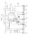
- the article transport facility is provided with one or more guide rails 2 (which corresponds to travel paths) that extend along a plurality of article processors 1, and one or more vehicles 3 which can move along with the guide rail or rails 2.
- Each vehicle 3 is configured to transport a container 5 (which corresponds to an article), which contains semiconductor substrates, among the plurality of article processors 1.
- the article processors 1 are configured to perform predetermined operations on the work-in-process parts during the manufacturing of the semiconductor substrates, etc.
- the vehicle 3 includes a vertically movable grip portion 4 for gripping the container 5 with the container suspended from the grip portion.
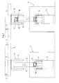
- the grip portion 4 is provided such that it can be raised and lowered between the reference raised position adjacent the vehicle 3 and the target transfer height for transferring articles to or from an article transfer station 7 (which corresponds to the transfer support portion) installed at a lower level than the vehicle 3, by winding and feeding out the wires 6 with the vehicle 3 stopped.
- Fig. 1 shows when the grip portion 4 is lowered to the target transfer height from the reference raised position as indicated by the downward-pointing arrow, and also when the grip portion 4 is raised from the target transfer height to the reference raised position as indicated by the upward-pointing arrow.
- Each station 7 consists of a support platform provided on the floor for supporting the container 5.
- the station 7 is configured to support a container 5 with the container 5 properly positioned by the engagement of grooves provided to the bottom of the container 5 with the engaging pins P (not shown in Fig. 1 ) provided to the support platform.
- the stations 7 are provided for the purpose of receiving containers 5, to which predetermined operations are to be performed by the article processors 1, from the vehicle(s) 3 or of delivering the containers 5, to which the predetermined operations have been performed by the article processors 1, to the vehicle(s) 3, and are located in correspondence with the plurality of article processors 1.
- the vehicle 3 is configured to move along the guide rail 2 with the grip portion 4 located in the reference raised position, and to deliver the container 5 to and receive a container 5 from a station 7 by raising and lowering the grip portion 4 between the reference raised position and the target transfer height with the vehicle stopped at the target stop position corresponding to the station 7 to which the article is to be transferred among the plurality of stations 7.
- the guide rail 2 is fixedly installed in the ceiling with the guide rail brackets 8.
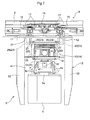
- the vehicle 3 has an upper vehicle body 9 located within the interior space of the guide rail 2, and a lower vehicle body 12 located below the guide rail 2 with the upper and lower vehicle bodies connected by the front and back connecting shafts 10, 11.
- the upper vehicle body 9 has a primary coil 14 such that the primary coil 14 is adjacent and faces the magnet 13 provided in the interior space of the guide rail 2.
- the upper vehicle body 9 is a linear motor type which obtains the propelling force from the linear motor which consists of the magnet 13 and the primary coil 14, and the vehicle 3 is configured to move along the guide rail 2 by this propelling force.
- Travel guide surfaces 16 for the travel wheels 15 provided to the upper vehicle body 9, and sway prevention guide surfaces 18 for the sway prevention wheels 17 provided to the upper vehicle body 9 are formed in the interior space of the guide rail 2.
- Electricity supply lines 19 are provided in the guide rail 2, and power receiving coils 20 are provided in the upper vehicle body 9. And alternating current is supplied to the electricity supply lines 19 to cause them to generate magnetic fields, which causes the power receiving coil 20 to generate the required electric power for the vehicle 3; thus, the electric power is supplied in a contactless manner.
- linear motor drive in which the propelling force is obtained by the linear motor is used as an example for the method to propel the upper vehicle body 9 in the present embodiment
- another method may also be used in which, for example, an electric motor for rotating the travel wheels 15 is provided and the travel wheels 15 are rotated by this electric motor to propel the upper vehicle body 9.
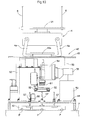
- the lower vehicle body 12 consists of a fore-and-aft frame 21 extending in the fore and aft direction of the vehicle 3, and a pair of front and back vertical frames 22 extending downwardly from the front end location and back end location respectively of the fore-and-aft frame 21.
- the lower vehicle body 12 is formed to have the shape of a bracket that opens downwardly in a side view, and the grip portion 4 is located in the central part in the fore and aft direction.
- a slide movement mechanism 23 which corresponds to the position adjustment means
- a vertical movement mechanism 24 which corresponds to the vertical movement means
- the grip portion 4 is supported by the slide movement mechanism 23 such that they can slide and move in the lateral direction of the vehicle 3 with respect to the fore-and-aft frame 21.
- the grip portion 4 is supported by the vertical movement mechanism 24 so as to be capable of vertically moving with respect to the fore-and-aft frame 21.
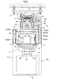
- the slide movement mechanism 23 has back and front pair of concave guide rails 25 which are fixed to the fore-and-aft frame 21 and which extend in the lateral direction of the vehicle 3, back and front pair of convex guide bodies 27 which are fixed to the vertical movement support 26 which supports the vertical movement mechanism 24, and which engage the concave guide rails 25, as well as a slide driving motor 28, a ball screw 29, and the connecting members 30 for moving the guide bodies 27 along the guide rails 25.
- the slide movement mechanism 23 moves the connecting member 30, which connects the ball screw 29 with the guide body 27, in one direction and the opposite direction along the lateral direction of the vehicle 3 by drivingly rotating the ball screw 29 with the slide driving motor 28.
- the guide bodies 27 are moved in one or the other direction along the lateral direction of the vehicle 3 with respect to the guide rail 25 to achieve the slide movements of the vertical movement mechanism 24 and the grip portion 4 with respect to the fore-and-aft frame 21 in the lateral direction of the vehicle 3.
- the vertical movement mechanism 24 includes the vertically movable body 31 to which the grip portion 4 is fixedly supported, a vertical movement driving motor 32 for raising and lowering the vertically movable body 31 with respect to the vertical movement support 26, a rotation drum 33, and the wires 6.
- the vertical movement mechanism 24 is configured to raise and lower the vertically movable body 31 while maintaining its approximately horizontal attitude by rotating the rotation drum 33 in one direction and in the opposite direction with the vertical movement driving motor 32 to wind and feed out the four wires 6 simultaneously.
- the grip portion 4 is raised and lowered with respect to the fore-and-aft frame 21 in this manner.
- the grip portion 4 is configured to be capable of being rotated about a vertical axis by the pivot shaft 34 with respect to the vertically movable body 31.
- a rotating driving motor 35 (which corresponds to the position adjustment means) for rotating the pivot shaft 34 about the vertical axis is provided, and the grip portion 4 is rotated about the vertical axis with respect to the fore-and-aft frame 21 by rotating the pivot shaft 34 about the vertical axis with this rotating driving motor 35.
- a pair of grippers 4a for gripping the flange 5a of the container 5 is provided to the grip portion 4. And the pair of grippers 4a are configured to switch between a gripping attitude in which the grippers are pivoted toward each other to grip the flange 5a, and a release attitude in which the pair of grippers 4a are pivoted away from each other to release the grip by a rotation of the gripper motor 41 in one direction and reverse direction.
- the carriage controller 36 which controls the travel operation of the vehicle 3 etc. is provided in the vehicle 3.
- the controllers and computers mentioned in the present specification have a CPU, memory, and a communication unit, and store algorithms which execute the functions described in the specification.
- the carriage controller 36 is configured to control the travel operation of the vehicle 3, the vertical movement operation of the grip portion 4, the position adjustment operation of the grip portion 4 in the lateral direction of the vehicle 3, the rotating operation about the vertical axis of the grip portion 4, and the switching of the grip portion 4 between the gripping attitude and the release attitude, based on commands from the managing computer which manages operations of the overall article transport facility, and on detected information from the various sensors provided to the vehicle 3.
- a stop plate detection sensor 37 which detects the stop plates installed, for example, in a side of the guide rail 2
- a vertical movement amount detection sensor 38 (which corresponds to the vertical movement detection means) which detects the amount of vertical movement of the grip portion 4 with respect to the reference raised position of the vehicle 3
- a lateral movement amount detection sensor 39 which detects the amount of a movement of the grip portion 4 in the lateral direction of the vehicle 3 with respect to the lateral width reference position (for example, middle position) of the vehicle 3
- a rotation amount detection sensor 40 which detects the amount of rotation in the rotational direction of the grip portion 4 about the vertical axis with respect to the standard rotation position (for example, a position in which the lateral direction and the fore and aft direction of the vehicle 3 coincides with the lateral direction and the fore and aft direction of the grip portion 4) of the vehicle 3.
- a target stop position corresponding to the installation position of each station 7 along the path of the guide rail 2, is defined, and a stop plate is provided at each target stop position.
- the vertical movement amount detection sensor 38, the lateral movement amount detection sensor 39, and the rotation amount detection sensor 40 consist of a rotary encoder provided, for example, to each of the vertical movement driving motor 32, the slide driving motor 28, and the rotating driving motor 35.
- the carriage controller 36 first stops the movement of the vehicle 3 to stop the vehicle 3 at the target stop position of the station 7 of transport origin when the stop plate detection sensor 37 detects the stop plate installed at the target stop position of the station 7 of transport origin. And with the vehicle 3 stopped at the target stop position, the carriage controller 36 controls the operation of the vertical movement driving motor 32 to lower the grip portion 4 from the reference raised position to the target transfer height based on the detected information from the vertical movement amount detection sensor 38.
- the carriage controller 36 When the grip portion 4 reaches the target transfer height, the carriage controller 36 operates the gripper motor 41 to switch the pair of grippers 4a to the gripping attitude, and causes the flange 5a of the container 5 to be gripped by the pair of grippers 4a to receive the container 5. Thereafter, the carriage controller 36 controls the operation of the vertical movement driving motor 32 to raise the grip portion 4 from the target transfer height to the reference raised position based on the detected information from the vertical movement amount detection sensor 38, then controls the travel operation of the vehicle 3 to move vehicle 3 to the target stop position for the station 7 of the transport destination.
- the carriage controller 36 is configured to unload the container 5 to the station 7 of the transport destination by controlling the vertical movement operation of the grip portion 4 and the operation of the gripper motor 41 when the vehicle 3 stops at the target stop position for the station 7 of the transport destination, similar to when the container 5 is received from the station 7 of the transport origin.
- the carriage controller 36 is configured to perform a transporting process of the container 5 from the station 7 of transport origin to the station 7 of transport destination when a transporting work mode is ordered as described above.
- the carriage controller 36 has a learning mode in addition to the transporting work mode and is configured to switch to the learning mode to perform a learning process before performing the transporting process in the transporting work mode.
- the learning process is structured to learn a target lowering amount when lowering the grip portion 4 from the reference raised position to the target transfer height for the station 7 in order to properly deliver a container 5 and receive a container 5 from each station 7 with the vehicle 3 stopped at the target stop position for the station 7, and to learn a position adjustment amount in the horizontal direction when raising and lowering the grip portion 4 with respect to the station 7 with the vehicle 3 stopped at the target stop position for the station 7.
- the learning device for an article transport facility is a device for performing this learning process, and is provided with a first learn assist member 42 (which corresponds to the detected member for learning) which can be attached to a station 7, and a second learn assist member 43 (which corresponds to the learn assist member) that can be gripped by the grip portion 4.
- learning control means 44 is provided for performing the learning process by controlling the travel operation of the vehicle 3 and the vertical movement operation of the grip portion 4, etc., with the first learn assist member 42 attached to the station 7 and with the second learn assist member 43 gripped by the grip portion 4, and a manually operated remote controller 45 (which corresponds to a command means) is provided, which issues a command to the learning control means 44 to operate in the learning mode.
- This remote controller 45 is a conventional controller, and includes switches, such as the manual operation buttons, a wired- or wireless-communications unit as well as other required circuits; but, it may or may not include a CPU or memory.
- the first learn assist member 42 consists of a plate-shaped body, in which a plurality (three) of the grooves 46 which are elongate holes and each of which engages each engaging pin P provided in the station 7.
- the first learn assist member 42 is configured to be attached to and be properly positioned with respect to the station 7.
- a detection mark 47 which is square in plan view is provided in the middle position on the first learn assist member 42 and the detection mark 47 is adapted to indicate the target transfer reference position when the first learn assist member 42 is attached to the station 7.
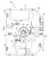
- the second learn assist member 43 includes a plate-shaped lower frame body 48 and a plate-shaped upper frame body 49, and a plurality of bar-shaped connection frame 50 which connect the lower frame body 48 and the upper frame body 49 with a distance therebetween. It is desirable for the second learn assist member 43 to have the same height and weight as the container 5.
- the same flange 49a as one of the container 5 is provided in the upper portion of the upper frame body 49, and the grip portion 4 is configured to grip the second learn assist member 43 by gripping the flange 49a with the pair of grippers 4a.
- a camera 51 (which corresponds to the imaging means) which is located in the central area of the space in plan view and whose imaging direction points downwardly, a lighting device (LED device) 52 which illuminates the field of view of the camera 51, an image-processing device 53 which can output information derived by processing the image captured by the camera 51, a learning member controller 54 which controls the image capturing process, etc. of the camera 51, a laser distance sensor 55 which detects the distance to the object located below by emitting a distance measuring light downward, and a communication device 56 which can communicate wirelessly a variety of information with the carriage controller 36 or the remote controller 45.
- a conventional camera such as a CCD camera, can be used as the camera 51.
- Three contact sensors 57 which detect a contact with an object below are provided to the lower frame body 48 to extend therethrough. The three contact sensors 57 are arranged so that each is located at each corner of a triangle in plan view.
- the learning member controller 54 is configured to control the operation of the camera 51, the lighting device 52, and the communication device 56, and to receive the information outputted from the image-processing device 53, the detected information from the laser distance sensor 55, and the detected information from the contact sensor 57. And the learning member controller 54 can communicate the detected information from the laser distance sensor 55 or the contact sensor 57 to the carriage controller 36 with the communication device 56, and can receive commands from the carriage controller 36, and also is configured to communicate to the carriage controller 36 the information derived by the image-processing device 53 from the image information captured by the camera 51.
- the learning control means 44 is configured to perform the learning process by controlling the travel operation of the vehicle 3, the operation of the vertical movement driving motor 32 which moves the grip portion 4 vertically, the operation of the slide driving motor 28 which makes the position adjustment of the grip portion 4 in the lateral direction of the vehicle 3, the operation of the rotating driving motor 35 which makes the position adjustment of the grip portion 4 in the rotational direction about an vertical axis, and the imaging operation of the camera 51.
- the learning control means 44 consists of the carriage controller 36 and the learning member controller 54.
- the remote controller 45 is configured to issue a command to the learning control means 44 to be in the learning mode when the operator operates the operating portion 58, selecting which stations 7 among a plurality of stations 7 are to be the subject of the learning process, and specifying in which order the learning process would be performed among the selected stations 7.
- the remote controller 45 is configured, by an operation of an accelerated lowering button 59 in the operating portion 58 by the operator, to switch between a command state in which an accelerated lowering command is issued to the learning control means 44 to lower the grip portion 4 at an increased lowering speed (for example, 6.0 m/min) which is faster than a set lowering speed (for example, 1.2 m/min) and a non-command state in which the accelerated lowering command is not issued.
- an increased lowering speed for example, 6.0 m/min
- a set lowering speed for example, 1.2 m/min
- the remote controller 45 is configured to switch to the command state by a manual operation of the operator to switch from the non-command state to the command state, which is a depression of the increased-speed lowering button 59, and is configured to return to the non-command state by a release of the manual operation. That is, the remote controller 45 is in the command state only while the increased-speed lowering button 59 is being depressed by the operator, and returns to the non-command state if the depressing operation is released.
- the learning control means 44 is configured to execute a learning process, with the first learn assist member 42 attached to the station 7 and with the grip portion 4 gripping the second learn assist member 43, by an order to commence the learning mode issued by the remote controller 45.
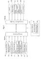
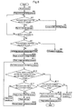
- the learning process for one of the stations 7 is described next based on the flow chart shown in Fig. 8 .
- the learning process described below is repeated when performing the learning process for a plurality of stations 7.
- the learning control means 44 performs a travel process (#1) for controlling the travel operation of the vehicle 3 based on the detected information from the stop plate detection sensor 37 to cause the vehicle 3 to travel to the target stop position for the station 7.
- the learning control means 44 performs a grip portion lowering process (#2) for controlling the operation of the vertical movement driving motor 32 to lower the grip portion 4 at a set downward speed with the grip portion 4 adjusted to the standard adjustment position by means of the slide driving motor 28 and the rotating driving motor 35.
- the learning control means 44 performs a lowering process by performing the travel process and the grip portion lowering process.
- the standard adjustment position is, for example, a position in which the center of the grip portion 4 coincides with the center of the vehicle 3 in the lateral direction of the vehicle 3, and in which the lateral direction and the fore and aft direction of the grip portion 4 coincide with the lateral direction and the fore and aft direction of the vehicle 3 in the angular direction about a vertical axis.
- the learning control means 44 continues to lower the grip portion 4 at the set lowering speed during the execution of the grip portion lowering process if the increased-speed lowering command has not been issued by the remote controller 45, and performs a speed increase process for controlling the operation of the vertical movement driving motor 32 (#3-#5) to lower the grip portion 4 at an increased lowering speed which is greater than the set lowering speed if the increased-speed lowering command has been issued by the remote controller 45.
- the learning control means 44 controls the operation of the vertical movement driving motor 32 to lower the grip portion 4 at the increased lowering speed which is greater than the set lowering speed if the increased-speed lowering command is issued by the remote controller 45 during an execution of the lowering process. Therefore, the grip portion 4 can be lowered at a greater lowering speed to shorten the time to lower the grip portion with a simple operation by the operator of issuing the increased-speed lowering command by means of the remote controller 45.
- the learning control means 44 detects that the bottom of the second learn assist member 43 contacted the upper surface of the first learn assist member 42 on the station 7 by sensing that all of the three contact sensors 57 provided to the second learn assist member 43 contacted the upper surface of the first learn assist member 42, it stops the lowering of the grip portion 4 by the vertical movement driving motor 32, and determines if the increased-speed lowering command has been issued by the remote controller 45 (#6, #7).
- the learning control means 44 performs a lowering amount calculating process in which a target lowering amount is derived (#8) based on the detected information from the vertical movement amount detection sensor 38 at that time.
- a target lowering amount is derived (#8) based on the detected information from the vertical movement amount detection sensor 38 at that time.
- target lowering amount for example, the lowering amount from the reference raised position until it detects the contact of the second learn assist member 43 can be derived as the target lowering amount, or a correction added to that lowering amount can be derived as the target lowering amount.
- the three contact sensors 57 are arranged so that each is located at each corner of a triangle in plan view; thus, the three contact sensors 57 are arranged and distributed to be well-balanced in the horizontal direction. Since the contacting of the bottom of the second learn assist member 43 with the upper surface of the first learn assist member 42 of the station 7 is detected only if all of the three contact sensors 57 contact the upper surface of the first learn assist member 42, the contact of the bottom of the second learn assist member 43 can be accurately detected even if the second learn assist member 43 is tilted. Therefore, even if the second learn assist member 43 is tilted, accurate target lowering amount can be derived.
- the learning control means 44 performs an abnormal stop of the learning process treating it as an abnormal condition (#9).
- the learning control means 44 controls the operation of the vertical movement driving motor 32 based on the detected information from the vertical movement amount detection sensor 38 to raise and lower the grip portion 4 such as to position the second learn assist member 43 at the target height for and with respect to the first learn assist member 42 (#10). At this time, the learning control means 44 checks whether the second learn assist member 43 is located at the target height based on the detected information from the laser distance sensor 55.
- the target height is determined such that the distance between the camera 51 and the detection mark 47 is the optimal distance for the camera 51 to capture an image of the detection mark 47, and is, for example, where the grip portion 4 is raised by a set height (for example, 3mm) from the position at which the contact of the bottom of the second learn assist member 43 is detected.
- the learning control means 44 performs a positioning process by performing the travel process and the grip portion lowering process, and by raising and lowering the grip portion 4 such that the second learn assist member 43 is located at the target height.
- the learning control means 44 performs a first image capturing process for controlling the image capturing operation of the camera 51 to capture the detection mark 47 with the second learn assist member 43 located at the target height, and performs a deviation amount calculating process in which the reference position deviation amount in the horizontal direction between the imaging reference position defined in the center of field of view of the image and the detection mark 47 is derived based on the image information captured in the first image capturing process (#11, #12).
- the learning control means 44 waits for a set period of time (for example, 10 seconds) so that the swaying of the grip portion 4 is settled down before performing the first image capturing process is performed in order to accurately derive the reference position deviation amount by removing the effect of the swaying of the grip portion 4 as much as possible.
- a set period of time for example, 10 seconds
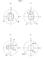
- the learning control means 44 derives the reference position deviation amounts based on the image information from the camera 51 in the deviation amount calculating process by means of the image processing device 53. And, as shown in Fig. 11 , the learning control means 44 is configured to derive, as the reference position deviation amounts, a lateral width deviation amount ⁇ between the detection mark 47 and the imaging reference position in the lateral direction of the vehicle 3 (see Fig. 11 (a) ), a rotation deviation amount ß between the detection mark 47 and the imaging reference position in the direction of rotation about an vertical axis (see Fig. 11 (b) ), and a fore and aft deviation amount ⁇ between the detection mark 47 and the imaging reference position in the fore and aft direction of the vehicle 3 (see Fig.
- FIG. 11 (c) ).
- the X-axis indicates the lateral direction of the vehicle 3
- the Y-axis indicates the fore and aft direction of the vehicle 3.
- a square standard imaging mark 60 (which corresponds to the imaging reference position) is pre-defined in the center of the field of view of the camera 51, and the standard imaging mark 60 has the same shape and size as the detection mark 47.
- the learning control means 44 derives the lateral width deviation amount ⁇ , rotation deviation amount ß, and fore and aft deviation amount ⁇ by comparing the relative position of the standard imaging mark 60 and the detection mark 47.
- the lateral width deviation amount ⁇ can be derived, for example, from the distance in the X direction between the center P1 of the standard imaging mark 60 and the center P2 of the detection mark 47.
- the rotation deviation amount ß can be derived, for example, from the angle in the direction of rotation about the vertical axis between the point P3 on the Y-axis of the standard imaging mark 60 and the point P4 of the detection mark 47 corresponding to P3.
- the fore and aft deviation amount ⁇ can be derived, for example, from the distance in the Y direction between the center P5 of the standard imaging mark 60 and the center P6 of the detection mark 47.
- the learning control means 44 determines whether the fore and aft deviation amount ⁇ is within a set tolerance range (for example, ⁇ 5.0mm), and if the fore and aft deviation amount ⁇ is within a set tolerance range, then the learning control means 44 performs a position adjustment amount calculating process (#13-#15) in which the position adjustment amount is derived from the lateral width deviation amount ⁇ and rotation deviation amount ß which were derived in the deviation amount calculating process.
- a set tolerance range for example, ⁇ 5.0mm
- the learning control means 44 performs the first deviation amount calculating process by performing the deviation amount calculating process and the position adjustment amount calculating process.
- the learning control means 44 carries out an abnormal stop of the learning operation as an abnormal condition, if the fore and aft deviation amount ⁇ is out of the set tolerance range (#16).
- this abnormal condition occurs, the target stop position at which the vehicle 3 stops is determined to have been displaced in the fore and aft direction of the vehicle 3, and the learning operation is performed again after the position of the stop plate has been adjusted.
- the learning control means 44 causes the camera 51 to capture the image of the detection mark 47 several times in the first image capturing process.
- the learning control means 44 controls the operation of the camera 51 to capture the image of the detection mark 47 one hundred times in 10 seconds, for example.
- the learning control means 44 derives unit image deviation amount data which shows the amount of deviation in the horizontal direction between the detection mark 47 and the imaging reference position for each of the plurality of images (for example, 100), and extracts data in an effective measurement range by removing data for which the deviation amount falls outside the effective measurement range from the plurality of unit image deviation amount data derived.
- the learning control means 44 takes an average of the plurality of the unit image deviation amount data to derive the reference position deviation amount.
- the learning control means 44 can derive an average value of the plurality of unit image deviation amount data, and use the average value as the reference position deviation amount.
- the learning control means 44 performs the positioning correcting process, in which the operations of the slide driving motor 28 and the rotating driving motor 35 are controlled, based on the detected information from the lateral movement amount detection sensor 39 and the rotation amount detection sensor 40(#18) to adjust the position of the second learn assist member 43 based on a movement adjustment amount derived based on the image information captured in the first image capturing process.
- the learning control means 44 derives the reference position deviation amount derived in the deviation amount calculating process as the movement adjustment amount in the positioning correcting process. That is, the learning control means 44 derives the lateral width deviation amount ⁇ and the rotation deviation amount ß, which are derived in the deviation amount calculating process, as the movement adjustment amount. For example, when the lateral width deviation amount ⁇ and rotation deviation amount ß fall outside the set tolerance range as shown in Figs. 11 (a) and 11 (b) , the learning control means 44 adjusts the position of the grip portion 4 in the lateral direction of the vehicle 3 such that the center P1 of the standard imaging mark 60 and the center P2 of the detection mark 47 coincide with each other as shown in Fig. 11 (d) , and adjusts the position of the grip portion 4 in the direction of rotation about a vertical axis such that the point P3 on the Y-axis of the standard imaging mark 60 and the point P4 of the detection mark 47 coincide with each other.
- the learning control means 44 After raising the grip portion 4 by a set amount (for example, 30mm), the learning control means 44 lowers the grip portion 4 until the contact by the bottom of the second learn assist member 43 is detected, and performs a retry process in which the operation of the vertical movement driving motor 32 is controlled based on the detected information from the vertical movement amount detection sensor 38 to raise and lower the grip portion 4 in order to position the second learn assist member 43 at the target height(#19).
- a set amount for example, 30mm
- the learning control means 44 performs a second image capturing process in which the imaging operation of the camera 51 is controlled to capture the image of the detection mark 47 (#20), and performs again the deviation amount calculating process in which the reference position deviation amount in the horizontal direction between the imaging reference position defined in the center of field of view of the image and the detection mark 47 based on the image information captured in the second image capturing process (#12).
- the learning control means 44 waits for a set period of time (for example, 10 seconds) so that the swaying of the grip portion 4 is settled down before performing the second image capturing process is performed in order to accurately derive the reference position deviation amounts by removing the effect of the swaying of the grip portion 4 as much as possible.
- a set period of time for example, 10 seconds
- the learning control means 44 determines whether the fore and aft deviation amount ⁇ derived in the repeated deviation amount calculation process is within a set tolerance range (for example, ⁇ 5.0mm), and if the fore and aft deviation amount ⁇ is within a set tolerance range, then the learning control means 44 performs a position adjustment amount calculating process (#13-#15) in which the amount of position adjustments is derived from the lateral width deviation amount ⁇ and rotation deviation amount 6 which were derived in the repeated deviation amount calculating process.
- a set tolerance range for example, ⁇ 5.0mm
- the learning control means 44 performs the second deviation amount calculating process by performing the deviation amount calculating process and the position adjustment amount calculating process.
- the detection mark 47 is determined to be located in the center of the field of view of the image. Then the reference position deviation amount can be derived accurately based on the image information captured in the first image capturing process, and the position adjustment amount can be accurately derived from the derived reference position deviation amount. On the other hand, if the reference position deviation amount, derived based on the image information captured in the first image capturing process, falls outside the set tolerance range, the detection mark 47 is determined to be located in an edge area of the field of view of the image.
- the positioning correcting process is performed accordingly and a position adjustment of the second learn assist member is carried out based on the movement adjustment amount derived based on the image information captured in the first image capturing process to position the detection mark 47 in the center of field of view of the image.
- the learning control means 44 can accurately derive the reference position deviation amount based on the image information captured in the second image capturing process, and can accurately derive the position adjustment amount by taking into consideration or by adding not only the reference position deviation amount but also the movement adjustment amount.
- the learning control means 44 determines whether fore and aft deviation amount ⁇ is within the set tolerance range (for example, ⁇ 5.0mm) in the second deviation amount calculating process after performing the positioning correcting process (#18), even if, for example, the fore and aft deviation amount ⁇ falls outside the set tolerance range (for example, ⁇ 5.0mm) in the first deviation amount calculating process, by performing the positioning correcting process, the fore and aft deviation amount ⁇ may come to be within the set tolerance range (for example, ⁇ 5.0mm) in the second deviation amount calculating process. Therefore, because a deviation in the fore and aft direction of the vehicle 3 can be corrected by an execution of the positioning correcting process, the position adjustment amount can be learned without abnormal conditions occurring unnecessarily.
- the learning control means 44 causes the camera 51 to capture the image of the detection mark 47 several times in the second image capturing process.
- the learning control means 44 controls the operation of the camera 51 to capture the image of the detection mark 47, for example, one hundred times in 10 seconds.
- the learning control means 44 derives unit image deviation amount data which shows the amount of deviation in the horizontal direction between the detection mark 47 and the imaging reference position for each of the plurality of images (for example, 100), and extracts data in an effective measurement range by removing data for which the deviation amount falls outside an effective measurement range from the plurality of unit image deviation amount data derived.
- the learning control means 44 takes an average of the plurality of the unit image deviation amount data to derive the reference position deviation amount.
- the learning control means 44 can derive an average value of the plurality of unit image deviation amount data, and use the average value as the reference position deviation amount.
- the learning control means 44 carries out an abnormal stop of the learning operation treating it as an abnormal condition, if the number of times of execution of the deviation amount calculating process executed after execution of the positioning correcting process reaches a permitted number (for example, 4 times) (#21). Thus, if or when the total number of times the second deviation amount calculating process has been executed becomes greater than the permitted number, the learning control means 44 determines that to be an abnormal condition in which repeated execution of the positioning correcting process would not cause the reference position deviation amount to fall within the set tolerance range.
- a permitted number for example, 4 times
- the learning control means 44 After performing the deviation amount calculating process based on the first image capturing process and the first deviation amount calculating process by execution of the position adjustment amount calculating process, or the deviation amount calculating process based on the second image capturing process and the second deviation amount calculating process by execution of the position adjustment amount calculating process, the learning control means 44 performs a grip portion rising process in which the operation of the vertical movement driving motor 32 is controlled in order to raise the grip portion 4 at a set raising speed which is greater than the set lowering speed (#22).
- the detection mark 47 is determined to be located in the center of the field of view of the image. Then the reference position deviation amount can be derived accurately based on the image information captured in the first image capturing process, and the position adjustment amount can be accurately derived from the derived reference position deviation amount.
- the detection mark 47 is determined to be located in an edge area of the field of view of the image.
- the positioning correcting process is performed accordingly and a position adjustment of the second learn assist member is carried out based on the movement adjustment amount derived based on the image information captured in the first image capturing process to position the detection mark 47 in the center of field of view of the image.
- the learning control means 44 can derive the reference position deviation amount accurately based on the image information captured in the second image capturing process, and can derive the position adjustment amount accurately by taking into consideration or by adding not only the reference position deviation amount but also the movement adjustment amount.
- the positioning step is performed in which the grip portion 4 is raised and lowered such that the second learn assist member 43 is located at the target height for the first learn assist member 42.
- a first imaging step is performed in which the camera 51 is caused to capture the image of the detection mark 47, and the reference position deviation amount in the horizontal direction between the imaging reference position and the detection mark 47 is derived based on the image information captured in the first imaging step and a first deviation amount calculating step is performed in which position adjustment amount is derived from the derived reference position deviation amount.
- the positioning correcting step is performed, in which the slide driving motor 28 and the rotating driving motor 35 are operated, to adjust the position of the second learn assist member 43 based on the movement adjustment amount derived based on the image information captured in the first imaging step.
- a second imaging step is performed in which the camera 51 is caused to capture the image of the detection mark 47, and the reference position deviation amount in the horizontal direction between the imaging reference position and the detection mark 47 is derived based on the image information captured in the second imaging step and a second deviation amount calculating step is performed in which position adjustment amount is derived from the derived reference position deviation amount and the movement adjustment amount.
- the present invention can be used as a learning device and a learning method for an article transport facility used in a clean room, or in other article processing facilities, etc.
Landscapes
- Engineering & Computer Science (AREA)
- Mechanical Engineering (AREA)
- Automation & Control Theory (AREA)
- Control And Safety Of Cranes (AREA)
Claims (12)
- Lernvorrichtung für eine Artikeltransportanlage, wobei die Lernvorrichtung aufweist:ein Fahrzeug (3), das konfiguriert ist, um sich entlang einem Fahrweg (2) zu bewegen, und das einen Greifabschnitt (4) aufweist, um einen Gegenstand zu greifen, wobei der Gegenstand von diesem herabhängt,eine Vertikalbewegungseinrichtung (24), um den Greifabschnitt bezüglich des Fahrzeugs anzuheben und abzusenken,eine Positionseinstelleinrichtung (23) zum Einstellen einer Position des Greifabschnittes in horizontaler Richtung bezüglich des Fahrzeugs,wobei Gegenstände zu einem Transfer-Tragabschnitt (7), der sich unterhalb des Laufwegs befindet, hin und von diesem weg transferiert werden, und zwar durch Anheben und Absenken des Greifabschnittes, wobei das Fahrzeug an einer Soll-Stoppposition im Laufweg gestoppt ist, weiter aufweisend:ein erstes Lernunterstützungselement (42), das konfiguriert ist, um an dem Transfer-Tragabschnitt befestigt zu werden, und das eine Erfassungsmarke (47) aufweist, um eine Position anzuzeigen, die einer Soll-Transferreferenzposition in horizontaler Richtung für den Transfer-Tragabschnitt entspricht, wobei das erste Lernunterstützungselement an dem Transfer-Tragabschnitt befestigt ist;ein zweites Lernunterstützungselement (43), das konfiguriert ist, um durch den Greifabschnitt gegriffen zu werden, und das eine Bildgebungseinrichtung (51) zum Aufnehmen eines Bildes einer Zone unterhalb des Greifabschnittes aufweist, um ein Bild der Erfassungsmarke aufzunehmen, wobei der Greifabschnitt das zweite Lernunterstützungselement greift;eine Lernsteuereinrichtung (44) zum Steuern einer Fahrtoperation des Fahrzeugs, einer Vertikalbewegungsoperation der Vertikalbewegungseinrichtung, einer Einstelloperation der Positionseinstelleinrichtung, und einer Bildgebungsoperation der Bildgebungseinrichtung, und zum Lernen eines Positionseinstellausmaßes in horizontaler Richtung, beim Anheben oder Absenken des Greifabschnitts bezüglich des Transfer-Tragabschnittes, wobei das Fahrzeug an der Soll-Stoppposition bezüglich des Transfer-Tragabschnittes gestoppt ist;die Lernsteuereinrichtung konfiguriert ist, um durchzuführen:einen Positionierprozess, bei dem der Greifabschnitt angehoben oder abgesenkt wird, um das zweite Lernunterstützungselement, das durch den Greifabschnitt gegriffen wird, auf der Sollhöhe bezüglich des ersten Lernunterstützungselementes zu positionieren, das an dem Transfer-Tragabschnitt befestigt ist, wobei das Fahrzeug in die Soll-Stoppposition für den Transfer-Tragabschnitt bewegt wurde, und wobei der Greifabschnitt durch die Positionseinstelleinrichtung auf eine Standardeinstellposition eingestellt wurde;einen ersten Bildaufnahmeprozess, bei dem die Bildgebungseinrichtung veranlasst wird, ein Bild der Erfassungsmarke aufzunehmen, nachdem der Positionierprozess durchgeführt wurde;einen ersten Abweichungsausmaß-Berechnungsprozess, bei dem ein Referenzpositions-Abweichungsausmaß in horizontaler Richtung zwischen der in einer Bildfeldmitte definierten Bildgebungs-Referenzposition und der Erfassungsmarke hergeleitet wird, basierend auf Bildinformation, die beim ersten Bildaufnahmeprozess aufgenommen wurde, um ein Positionseinstellungsausmaß aus dem hergeleiteten Referenzpositions-Abweichungsausmaß herzuleiten,dadurch gekennzeichnet, dass die Lernsteuereinrichtung konfiguriert ist, um weiter durchzuführeneinen Positionierkorrekturprozess, bei dem die Positionseinstelleinrichtung betrieben wird, um eine Position des zweiten Lernunterstützungselementes basierend auf dem Bewegungseinstellausmaß einzustellen, das basierend auf der im ersten Bildaufnahmeprozess aufgenommenen Bildinformation hergeleitet wurde, falls das Referenzpositions-Abweichungsausmaß, das beim ersten Abweichungsausmaß-Berechnungsprozess hergeleitet wurde, außerhalb eines festgelegten Toleranzbereichs liegt;einen zweiten Bildaufnahmeprozess, bei dem die Bildgebungseinrichtung veranlasst wird, ein Bild der Erfassungsmarke aufzunehmen, nachdem der Positionierkorrekturprozess durchgeführt wurde; undeinen zweiten Abweichungsausmaß-Berechnungsprozess, bei dem ein Referenzpositions-Abweichungsausmaß in horizontaler Richtung zwischen der in der Bildfeldmitte definierten Bildgebungs-Referenzposition und der Erfassungsmarke hergeleitet wird, basierend auf der Bildinformation, die beim zweiten Bildaufnahmeprozess aufgenommen wurde, um ein Positionseinstellungsausmaß aus dem hergeleiteten Referenzpositions-Abweichungsausmaß und dem Bewegungseinstellausmaß herzuleiten.
- Lernvorrichtung für eine Artikeltransportanlage nach Anspruch 1, dadurch gekennzeichnet, dass die Lernsteuereinrichtung konfiguriert ist, um das Referenzpositions-Abweichungsausmaß, das beim ersten Abweichungsausmaß-Berechnungsprozess hergeleitet wurde, als das Bewegungseinstellausmaß in dem Positionierkorrekturprozess herzuleiten.
- Lernvorrichtung für eine Artikeltransportanlage nach Anspruch 1, dadurch gekennzeichnet, dass, wenn das Referenzpositions-Abweichungsausmaß, das im zweiten Abweichungsausmaß-Berechnungsprozess hergeleitet wurde, außerhalb des festgelegten Toleranzbereichs liegt, die Lernsteuereinrichtung konfiguriert ist, erneut den Positionierkorrekturprozess, den zweiten Bildaufnahmeprozess und den zweiten Abweichungsausmaß-Berechnungsprozess durchzuführen, und zu bestimmen, dass ein abnormer Zustand aufgetreten ist, falls eine Anzahl von Malen, dass der zweiten Abweichungsausmaß-Berechnungsprozess durchgeführt wurde, eine zulässige Anzahl übersteigt.
- Lernvorrichtung für eine Artikeltransportanlage nach Anspruch 1, dadurch gekennzeichnet, dass die Positionseinstelleinrichtung konfiguriert ist, eine Position des Greifabschnittes in einer seitlichen Richtung des Fahrzeugs in horizontaler Richtung einzustellen und den Greifabschnitt um eine vertikale Achse bezüglich des Fahrzeugs zu rotieren, und
die Lernsteuereinrichtung konfiguriert ist, um ein seitliches Abweichungsausmaß in seitlicher Richtung des Fahrzeugs zwischen der Erfassungsmarke und der Bildgebungs-Referenzposition herzuleiten, und ein Rotations-Abweichungsausmaß, in Richtung einer Rotation um eine vertikale Achse zwischen der Erfassungsmarke und der Bildgebungs-Referenzposition, als das Referenzpositions-Abweichungsausmaß beim ersten Abweichungsausmaß-Berechnungsprozess und dem zweiten Abweichungsausmaß-Berechnungsprozess herzuleiten. - Lernvorrichtung für eine Artikeltransportanlage nach Anspruch 4, dadurch gekennzeichnet, dass die Lernsteuereinrichtung konfiguriert ist, ein Abweichungsausmaß in Richtung nach vorne und hinten, in Vorwärts- und Rückwärts-Richtung des Fahrzeugs, zwischen der Erfassungsmarke und der Bildgebungs-Referenzposition als das Referenzpositions-Abweichungsausmaß beim ersten Abweichungsausmaß-Berechnungsprozess und dem zweiten Abweichungsausmaß-Berechnungsprozess herzuleiten, und das Positionseinstellausmaß zu berechnen, falls das hergeleitete Abweichungsausmaß in Richtung nach vorn und nach hinten innerhalb eines festgelegten Toleranzbereichs liegt, und zu bestimmen, dass ein abnormer Zustand aufgetreten ist, falls das hergeleitete Abweichungsausmaß in Richtung nach vorn und nach hinten außerhalb des festgelegten Toleranzbereichs liegt.
- Lernvorrichtung für eine Artikeltransportanlage nach einem der Ansprüche 1 bis 5, dadurch gekennzeichnet, dass die Lernsteuereinrichtung konfiguriert ist, die Bildgebungseinrichtung zu veranlassen, ein Bild der Erfassungsmarke mehrere Male beim ersten Bildaufnahmeprozess und dem zweiten Bildaufnahmeprozess aufzunehmen, und Einzel-Bildabweichungsausmaßdaten herzuleiten, die das Ausmaß der Abweichung in horizontaler Richtung zwischen der Erfassungsmarke und der Bildgebungs-Referenzposition bei einem jeweiligen der Mehrzahl von Bildern bei dem ersten Abweichungsausmaß-Berechnungsprozess und dem zweiten Abweichungsausmaß-Berechnungsprozess zeigen, und Daten zu extrahieren, die in einem effektiven Messbereich liegen, dadurch dass Daten, bei denen das Abweichungsausmaß außerhalb des effektiven Messbereiches liegt, aus der Mehrzahl von Einzel-Bildabweichungsausmaßdaten entfernt werden, und einen Mittelwert aus der Mehrzahl von Einzel-Bildabweichungsausmaßdaten zu bilden, um das Referenzpositions-Abweichungsausmaß herzuleiten, falls eine Anzahl von extrahierten Einzel-Bildabweichungsausmaßdaten größer oder gleich einer festgelegten Anzahl ist.
- Lernvorrichtung für eine Artikeltransportanlage nach Anspruch 1, weiter aufweisend: eine manuell betätigte Steuereinrichtung (45) und eine Vertikalbewegungsausmaß-Erfassungseinrichtung (38) zum Erfassen eines Ausmaßes einer Vertikalbewegung des Greifabschnittes bezüglich des Fahrzeugs,
wobei die Lernsteuereinrichtung konfiguriert ist, ein Soll-Absenkausmaß zu lernen, wenn der Greifabschnitt aus einer Referenzanhebeposition auf die Soll-Transferhöhe bezüglich des Transfer-Tragabschnittes abgesenkt wird, wobei das Fahrzeug an der Soll-Stoppposition für den Transfer-Tragabschnitt gestoppt ist, und
wenn ein Lernmodus durch die manuell betätigte Kommandoeinrichtung angewiesen wird, bei durch den Greifabschnitt gegriffenem zweiten Lernunterstützungselement, die Lernsteuereinrichtung konfiguriert ist, einen Absenkprozess durchzuführen, bei dem eine Operation des Fahrzeugs gesteuert wird, um das Fahrzeug an der Soll-Stoppposition anzuhalten, und bei dem eine Operation der Vertikalbewegungseinrichtung gesteuert wird, um den Greifabschnitt bei festgelegter Absenkgeschwindigkeit abzusenken, und einen Absenkausmaß-Berechnungsprozess durchzuführen, bei dem ein Soll-Absenkausmaß hergeleitet wird, basierend auf Information, die von der Vertikalbewegungsausmaß-Erfassungseinrichtung erfasst wird, zu einem Zeitpunkt, bei dem eine Kontakterfassungseinrichtung (57), die an einer Unterseite des zweiten Lernunterstützungselementes vorgesehen ist, erfasst, dass die Unterseite des zweiten Lernunterstützungselementes während des Absenkprozesses den Transfer-Tragabschnitt berührt hat, und
wobei die Kommandoeinrichtung konfiguriert ist, um zwischen einem Kommandozustand, bei dem ein Befehl zu einem Absenken mit erhöhter Geschwindigkeit an die Lernsteuereinrichtung ausgegeben wird, um den Greifabschnitt mit erhöhter Absenkgeschwindigkeit abzusenken, die größer als die festgelegte Absenkgeschwindigkeit ist, und einem Nicht-Kommandozustand umzuschalten, bei dem der Befehl zum Absenken mit erhöhter Geschwindigkeit nicht ausgegeben wird, und wobei die Lernsteuereinrichtung konfiguriert ist, eine Operation der vertikalen Bewegung zu steuern, um den Greifabschnitt mit erhöhter Absenkgeschwindigkeit abzusenken, falls der Befehl zum Absenken mit erhöhter Geschwindigkeit durch die Kommandoeinrichtung ausgegeben wird, wenn der Absenkprozess gerade durchgeführt wird. - Lernvorrichtung für eine Artikeltransportanlage nach Anspruch 7, dadurch gekennzeichnet, dass die Lernsteuereinrichtung konfiguriert ist, zu bestimmen, dass ein abnormer Zustand aufgetreten ist, falls das Kommando zum Absenken mit erhöhter Geschwindigkeit durch die Kommandoeinrichtung ausgegeben wurde, wenn die Kontakterfassungseinrichtung erfasst, dass die Unterseite des zweiten Lernunterstützungselementes in Kontakt gekommen ist.
- Lernvorrichtung für eine Artikeltransportanlage nach Anspruch 7, dadurch gekennzeichnet, dass die Kommandoeinrichtung konfiguriert ist, in den Kommandozustand umzuschalten, und zwar durch eine manuelle Betätigung der Bedienperson für ein Umschalten aus dem Nicht-Kommandozustand in den Kommandozustand, und in den Nicht-Kommandozustand zurückzukehren, und zwar dadurch, dass eine Freigabe der manuellen Betätigung für ein Umschalten aus dem Nicht-Kommandozustand in den Kommandozustand erfolgt.
- Lernvorrichtung für eine Artikeltransportanlage nach einem der Ansprüche 7 bis 9, dadurch gekennzeichnet, dass die Lernsteuereinrichtung konfiguriert ist, einen Greifabschnitt-Anhebeprozess durchzuführen, bei dem eine Operation der Vertikalbewegungseinrichtung gesteuert wird, um den Greifabschnitt mit einer festgelegten Anhebegeschwindigkeit anzuheben, die größer als die festgelegte Absenkgeschwindigkeit ist, wenn der Greifabschnitt zu dem Fahrzeug angehoben wird, das an der Soll-Stoppposition gestoppt ist.
- Lernverfahren für eine Artikeltransportanlage, aufweisend
ein Fahrzeug, das konfiguriert ist, um sich entlang einem Fahrweg (2) zu bewegen, und das einen Greifabschnitt (4) aufweist, um einen Gegenstand zu greifen, wobei der Gegenstand von diesem herabhängt;
eine Vertikalbewegungseinrichtung (24), um den Greifabschnitt bezüglich des Fahrzeugs anzuheben und abzusenken;
eine Positionseinstelleinrichtung (23) zum Einstellen einer Position des Greifabschnittes in horizontaler Richtung bezüglich des Fahrzeugs;
wobei Gegenstände zu einem Transfer-Tragabschnitt (7), der sich unterhalb des Laufwegs befindet, hin und von diesem weg transferiert werden, und zwar durch Anheben und Absenken des Greifabschnittes, wobei das Fahrzeug an einer Soll-Stoppposition im Laufweg gestoppt ist, wobei das Verfahren umfasst:einen Positionierschritt zum Anheben und Absenken des Greifabschnittes, um ein zweites Lernunterstützungselement (43) auf einer Sollhöhe bezüglich eines ersten Lernunterstützungselementes (42) zu positionieren, das an dem Transfer-Tragabschnitt befestigt ist, wobei das erste Lernunterstützungselement an dem Transfer-Tragabschnitt befestigt ist, wobei das erste Lernunterstützungselement eine Erfassungsmarke (47) zum Angeben einer Position aufweist, die einer Soll-Transferreferenzposition in horizontaler Richtung für den Transfer-Tragabschnitt entspricht, wobei der Greifabschnitt das zweite Lernunterstützungselement greift, das eine Bildgebungseinrichtung (51) zum Aufnehmen eines Bildes einer Zone unterhalb des Greifabschnittes aufweist, um ein Bild der Erfassungsmarke aufzunehmen, wobei das Fahrzeug an der Soll-Stoppposition gestoppt ist, und wobei eine Position des Greifabschnittes durch die Positionseinstelleinrichtung auf eine Stahdardeinstellposition eingestellt ist;einen ersten Bildaufnahmeschritt, um die Bildgebungseinrichtung zu veranlassen, ein Bild der Erfassungsmarke aufzunehmen, nachdem der Positionierschritt durchgeführt wurde;einen ersten Abweichungsausmaß-Berechnungsschritt, bei dem ein Referenzpositions-Abweichungsausmaß in horizontaler Richtung zwischen der in einer Bildfeldmitte definierten Bildgebungs-Referenzposition und der Erfassungsmarke hergeleitet wird, basierend auf Bildinformation, die beim ersten Bildaufnahmeschritt aufgenommen wurde, um ein Positionseinstellausmaß in horizontaler Richtung herzuleiten, beim Anheben oder Absenken des Greifabschnitts bezüglich des Transfer-Tragabschnitts, wobei das Fahrzeug an der Soll-Stoppposition für den Transfer-Tragabschnitt gestoppt ist, und zwar von dem hergeleiteten Referenzpositions-Abweichungsausmaß, undeinen Positionierkorrekturschritt, bei dem die Positionseinstelleinrichtung betrieben wird, um eine Position des zweiten Lernunterstützungselementes basierend auf dem Bewegungseinstellausmaß einzustellen, das basierend auf der im ersten Bildaufnahmeschritt aufgenommenen Bildinformation hergeleitet wurde, wenn das Referenzpositions-Abweichungsausmaß, das beim ersten Abweichungsausmaß-Berechnungsschritt hergeleitet wurde, außerhalb eines festgelegten Toleranzbereichs liegt;einen zweiten Bildaufnahmeschritt, bei dem die Bildgebungseinrichtung veranlasst wird, ein Bild der Erfassungsmarke aufzunehmen, nachdem der Positionierkorrekturschritt durchgeführt wurde; undeinen zweiten Abweichungsausmaß-Berechnungsschritt, bei dem ein Referenzpositions-Abweichungsausmaß in horizontaler Richtung zwischen der in einer Bildfeldmitte definierten Bildgebungs-Referenzposition und der Erfassungsmarke hergeleitet wird, basierend auf Bildinformation, die beim zweiten Bildaufnahmeschritt aufgenommen wurde, um ein Positionseinstellungsausmaß aus dem hergeleiteten Referenzpositions-Abweichungsausmaß und dem Bewegungseinstellausmaß herzuleiten. - Lernverfahren für eine Artikeltransportanlage nach Anspruch 11, weiter aufweisend: eine manuell betätigte Kommandoeinrichtung (45) und eine Vertikalbewegungsausmaß-Erfassungseinrichtung (38) zum Erfassen eines Ausmaßes einer Vertikalbewegung des Greifabschnittes bezüglich des Fahrzeugs,
wobei, wenn ein Lernmodus durch die manuell betätigte Kommandoeinrichtung angewiesen wird, bei durch den Greifabschnitt gegriffenem zweiten Lernunterstützungselement, ein Absenkschritt durchgeführt wird, bei dem eine Operation des Fahrzeugs gesteuert wird, um das Fahrzeug an der Soll-Stoppposition zu stoppen, und bei dem eine Operation der Vertikalbewegungseinrichtung gesteuert wird, um den Greifabschnitt mit festgelegter Absenkgeschwindigkeit abzusenken, und ein Absenkausmaß-Berechnungsschritt durchgeführt wird, bei dem ein Soll-Absenkausmaß basierend auf Information hergeleitet wird, die von der Vertikalbewegungsausmaß-Erfassungseinrichtung erfasst wird, zu einem Zeitpunkt, bei dem eine Kontakterfassungseinrichtung, die an einer Unterseite des zweiten Lernunterstützungselementes vorgesehen ist, erfasst, dass die Unterseite des zweiten Lernunterstützungselementes den Transfer-Tragabschnitt während des Absenkschrittes berührt hat, und wobei die Kommandoeinrichtung konfiguriert ist, zwischen einem Kommandozustand, bei dem ein Kommando zum Absenken mit erhöhter Geschwindigkeit an die Lernsteuereinrichtung ausgegeben wird, um den Greifabschnitt mit erhöhter Absenkgeschwindigkeit abzusenken, die größer als die festgelegte Absenkgeschwindigkeit ist, und einem Nicht-Kommandozustand umzuschalten, bei dem der Befehl zum Absenken mit erhöhter Geschwindigkeit nicht ausgegeben wird, und wobei eine Operation der Vertikalbewegung gesteuert wird, um den Greifabschnitt mit der höheren Absenkgeschwindigkeit abzusenken, falls der Befehl zum Absenken mit erhöhter Geschwindigkeit durch die Kommandoeinrichtung ausgegeben wird, wenn der Absenkschritt gerade durchgeführt wird.
Applications Claiming Priority (3)
| Application Number | Priority Date | Filing Date | Title |
|---|---|---|---|
| JP2008190015A JP5267853B2 (ja) | 2008-07-23 | 2008-07-23 | 物品搬送設備における学習装置 |
| JP2008190014A JP5339118B2 (ja) | 2008-07-23 | 2008-07-23 | 物品搬送設備における学習装置及び学習方法 |
| PCT/JP2009/061928 WO2010010795A1 (ja) | 2008-07-23 | 2009-06-30 | 物品搬送設備における学習装置及び学習方法 |
Publications (3)
| Publication Number | Publication Date |
|---|---|
| EP2305594A1 EP2305594A1 (de) | 2011-04-06 |
| EP2305594A4 EP2305594A4 (de) | 2013-07-03 |
| EP2305594B1 true EP2305594B1 (de) | 2015-04-08 |
Family
ID=41570261
Family Applications (1)
| Application Number | Title | Priority Date | Filing Date |
|---|---|---|---|
| EP09800310.6A Active EP2305594B1 (de) | 2008-07-23 | 2009-06-30 | Lernvorrichtung und lernverfahren in einer produktförderungsanlage |
Country Status (6)
| Country | Link |
|---|---|
| US (1) | US8374420B2 (de) |
| EP (1) | EP2305594B1 (de) |
| KR (1) | KR101305265B1 (de) |
| CN (1) | CN102105384B (de) |
| TW (1) | TWI412484B (de) |
| WO (1) | WO2010010795A1 (de) |
Families Citing this family (51)
| Publication number | Priority date | Publication date | Assignee | Title |
|---|---|---|---|---|
| US8789682B2 (en) * | 2011-07-11 | 2014-07-29 | Tait Towers Manufacturing, LLC | Engagement article, load positioning system, and process for positioning loads |
| JP5842276B2 (ja) * | 2012-02-28 | 2016-01-13 | 株式会社ダイフク | 物品移載装置 |
| JP5931605B2 (ja) * | 2012-06-28 | 2016-06-08 | 株式会社ファブリカトヤマ | 容器供給装置 |
| US8903516B2 (en) * | 2012-09-04 | 2014-12-02 | United Technologies Corporation | Visual alignment system and method for workpiece marking |
| JP6295242B2 (ja) * | 2013-02-15 | 2018-03-14 | 村田機械株式会社 | 搬送台車、搬送台車の駆動制御方法、及び搬送台車の駆動制御プログラム |
| EP2796402A1 (de) * | 2013-04-25 | 2014-10-29 | Mecatronia Automatizaciones S.L. | System und Steuerungsverfahren zur Positionierung von Brückenkranen |
| JP6007880B2 (ja) * | 2013-10-10 | 2016-10-12 | 株式会社ダイフク | 天井搬送車 |
| US20150330054A1 (en) * | 2014-05-16 | 2015-11-19 | Topcon Positioning Systems, Inc. | Optical Sensing a Distance from a Range Sensing Apparatus and Method |
| TWI554463B (zh) * | 2014-05-28 | 2016-10-21 | 行政院原子能委員會核能研究所 | 三維天車系統之適應模糊滑動影像追蹤控制裝置 |
| BR112017003874A2 (pt) | 2014-09-15 | 2018-01-23 | Crown Equip Corp | empilhadeira. |
| JP6304084B2 (ja) * | 2015-03-16 | 2018-04-04 | 株式会社ダイフク | 物品搬送設備及び検査用治具 |
| JP6330714B2 (ja) * | 2015-04-09 | 2018-05-30 | 株式会社ダイフク | 物品搬送設備及び物品搬送設備の保守作業方法 |
| CN105088172B (zh) * | 2015-09-21 | 2017-12-01 | 京东方科技集团股份有限公司 | 膜厚控制系统及膜厚控制方法 |
| KR101616049B1 (ko) * | 2015-11-04 | 2016-04-27 | 주식회사 지티에스엠 | 반송 로봇 티칭을 위한 지그 및 그를 이용한 반송 로봇 티칭 정보 획득 방법 |
| JP6641926B2 (ja) * | 2015-11-26 | 2020-02-05 | 株式会社ダイフク | 物品搬送設備 |
| CN106094822B (zh) * | 2016-06-27 | 2022-12-16 | 中国计量大学 | 基于辅助定位装置的惯性导引车定位方法及惯性导引车 |
| JP2019531560A (ja) | 2016-07-05 | 2019-10-31 | ナウト, インコーポレイテッドNauto, Inc. | 自動運転者識別システムおよび方法 |
| EP3497405B1 (de) | 2016-08-09 | 2022-06-15 | Nauto, Inc. | System und verfahren zur präzisionsortung und kartierung |
| US10733460B2 (en) | 2016-09-14 | 2020-08-04 | Nauto, Inc. | Systems and methods for safe route determination |
| CN109789970B (zh) * | 2016-10-07 | 2021-06-11 | 村田机械株式会社 | 自动仓库 |
| EP3535646A4 (de) | 2016-11-07 | 2020-08-12 | Nauto, Inc. | System und verfahren zur bestimmung von fahrerablenkung |
| JP6601385B2 (ja) * | 2016-12-27 | 2019-11-06 | 株式会社ダイフク | 学習用支持装置 |
| JP6397062B2 (ja) * | 2017-01-26 | 2018-09-26 | 本田技研工業株式会社 | ワークの位置検出方法とハンガーの保守作業要否判断方法 |
| CN110248878B (zh) * | 2017-02-07 | 2021-03-12 | 村田机械株式会社 | 输送系统和输送方法 |
| JP6743750B2 (ja) * | 2017-04-14 | 2020-08-19 | 株式会社ダイフク | 物品搬送設備 |
| JP7164314B2 (ja) * | 2017-04-28 | 2022-11-01 | ベシ スウィッツァーランド エージー | 部品を基板上に搭載する装置及び方法 |
| US10453150B2 (en) | 2017-06-16 | 2019-10-22 | Nauto, Inc. | System and method for adverse vehicle event determination |
| US10889449B2 (en) | 2017-09-25 | 2021-01-12 | Canon Kabushiki Kaisha | Transport system and manufacturing method of article |
| KR102247038B1 (ko) * | 2017-10-30 | 2021-04-30 | 세메스 주식회사 | 호이스트 모듈의 위치 보정 방법 |
| JP7097691B2 (ja) * | 2017-12-06 | 2022-07-08 | 東京エレクトロン株式会社 | ティーチング方法 |
| JP6863263B2 (ja) * | 2017-12-18 | 2021-04-21 | 株式会社ダイフク | 物品収納設備 |
| US10984524B2 (en) * | 2017-12-21 | 2021-04-20 | Advanced Ion Beam Technology, Inc. | Calibration system with at least one camera and method thereof |
| US11392131B2 (en) | 2018-02-27 | 2022-07-19 | Nauto, Inc. | Method for determining driving policy |
| US11348817B2 (en) * | 2018-11-29 | 2022-05-31 | Taiwan Semiconductor Manufacturing Co., Ltd. | Wafer transport system and method for transporting wafers |
| JP7128362B2 (ja) * | 2019-08-30 | 2022-08-30 | 株式会社Fuji | 作業機 |
| CN110615362B (zh) * | 2019-10-28 | 2020-12-29 | 中建三局集团有限公司 | 一种塔式起重机智能控制系统及方法 |
| JP7176545B2 (ja) * | 2020-03-17 | 2022-11-22 | 株式会社ダイフク | 物品収納設備 |
| US12377550B2 (en) | 2020-05-15 | 2025-08-05 | Aulton New Energy Automotive Technology Group | Visual positioning system, battery swapping device, and battery swapping control method |
| US12448254B2 (en) * | 2020-06-08 | 2025-10-21 | Murata Machinery, Ltd. | Overhead transport vehicle, and method of controlling raising/lowering of gripping unit |
| KR102754089B1 (ko) * | 2020-10-05 | 2025-01-14 | 에스케이하이닉스 주식회사 | 오버헤드 호이스트 이송 시스템 |
| US12050153B2 (en) * | 2020-11-13 | 2024-07-30 | Taiwan Semiconductor Manufacturing Company Ltd. | Method for monitoring transport vehicle and maintenance thereof |
| EP4270774A4 (de) * | 2020-12-24 | 2024-05-08 | Panasonic Intellectual Property Management Co., Ltd. | Motorsteuerungsvorrichtung |
| CN112765888B (zh) * | 2021-01-22 | 2022-01-28 | 深圳市鑫路远电子设备有限公司 | 一种精确计量胶量的真空供胶的信息处理方法及系统 |
| AU2022258326A1 (en) | 2021-04-12 | 2023-11-23 | Structural Services, Inc. | Systems and methods for assisting a crane operator |
| US12195306B2 (en) | 2021-04-12 | 2025-01-14 | Structural Services, Inc. | Systems and methods for identifying and locating building material objects |
| KR102470517B1 (ko) * | 2021-04-21 | 2022-11-25 | 주식회사 에스에프에이 | 반송 시스템, 반송 시스템에서의 반송차 교시 방법, 반송차 및 반송차의 구동방법 |
| CN113921457B (zh) * | 2021-09-30 | 2022-05-24 | 弥费实业(上海)有限公司 | 抓取装置及空中运输车 |
| TW202346170A (zh) * | 2022-01-28 | 2023-12-01 | 日商大福股份有限公司 | 物品搬送車 |
| US11932519B2 (en) | 2022-07-06 | 2024-03-19 | Magnetek, Inc. | Dynamic maximum frequency in a slow-down region for a material handling system |
| JP7746940B2 (ja) * | 2022-08-18 | 2025-10-01 | 株式会社ダイフク | 物品昇降装置 |
| CN116443730B (zh) * | 2023-06-13 | 2023-08-25 | 上海新创达半导体设备技术有限公司 | 一种辅助天车补偿校正系统及控制方法 |
Family Cites Families (13)
| Publication number | Priority date | Publication date | Assignee | Title |
|---|---|---|---|---|
| JP3249409B2 (ja) * | 1996-11-25 | 2002-01-21 | 三菱重工業株式会社 | 吊荷の着床位置決め方法およびその装置 |
| JP3335912B2 (ja) * | 1998-06-26 | 2002-10-21 | 株式会社東芝 | 搬送システム |
| WO2003008325A1 (en) * | 2001-07-17 | 2003-01-30 | Kabushiki Kaisha Toyota Jidoshokki | Industrial vehicle equipped with material handling work controller |
| CN1996553A (zh) * | 2001-08-31 | 2007-07-11 | 阿赛斯特技术公司 | 用于半导体材料处理系统的一体化机架 |
| US6802413B2 (en) * | 2001-10-19 | 2004-10-12 | Daifuku Co., Ltd. | Hanging conveyance equipment and learning system therefor |
| JP4151002B2 (ja) * | 2001-10-19 | 2008-09-17 | 株式会社ダイフク | 吊下搬送設備とその学習装置 |
| JP4296914B2 (ja) * | 2003-12-08 | 2009-07-15 | アシスト テクノロジーズ ジャパン株式会社 | 位置教示装置及びそれを備えた搬送システム |
| JP4329034B2 (ja) * | 2004-08-09 | 2009-09-09 | 株式会社ダイフク | 物品搬送装置 |
| JP4813781B2 (ja) * | 2004-08-24 | 2011-11-09 | 三菱重工業株式会社 | 検査装置付クレーン |
| JP4543833B2 (ja) * | 2004-08-31 | 2010-09-15 | ムラテックオートメーション株式会社 | 懸垂式昇降搬送装置における搬送台車の教示装置 |
| JP4122521B2 (ja) * | 2005-01-17 | 2008-07-23 | 村田機械株式会社 | 天井走行車システム |
| KR100669250B1 (ko) * | 2005-10-31 | 2007-01-16 | 한국전자통신연구원 | 인공표식 기반의 실시간 위치산출 시스템 및 방법 |
| JP4756367B2 (ja) * | 2006-08-17 | 2011-08-24 | 株式会社ダイフク | 物品収納設備 |
-
2009
- 2009-06-30 EP EP09800310.6A patent/EP2305594B1/de active Active
- 2009-06-30 WO PCT/JP2009/061928 patent/WO2010010795A1/ja not_active Ceased
- 2009-06-30 CN CN2009801286836A patent/CN102105384B/zh active Active
- 2009-06-30 KR KR1020117000018A patent/KR101305265B1/ko active Active
- 2009-06-30 US US13/054,304 patent/US8374420B2/en active Active
- 2009-07-03 TW TW098122553A patent/TWI412484B/zh active
Also Published As
| Publication number | Publication date |
|---|---|
| US8374420B2 (en) | 2013-02-12 |
| WO2010010795A1 (ja) | 2010-01-28 |
| CN102105384A (zh) | 2011-06-22 |
| KR20110036033A (ko) | 2011-04-06 |
| KR101305265B1 (ko) | 2013-09-06 |
| EP2305594A4 (de) | 2013-07-03 |
| CN102105384B (zh) | 2013-07-17 |
| EP2305594A1 (de) | 2011-04-06 |
| TWI412484B (zh) | 2013-10-21 |
| TW201016584A (en) | 2010-05-01 |
| US20110262004A1 (en) | 2011-10-27 |
Similar Documents
| Publication | Publication Date | Title |
|---|---|---|
| EP2305594B1 (de) | Lernvorrichtung und lernverfahren in einer produktförderungsanlage | |
| CN106865086B (zh) | 物品输送设备 | |
| US20200118853A1 (en) | Transport system and transport method | |
| US9682842B2 (en) | Automated roll transport facility | |
| US20170247190A1 (en) | Article Transport Facility | |
| JP4438736B2 (ja) | 搬送装置 | |
| US12119249B2 (en) | Conveyance vehicle | |
| US20230322504A1 (en) | Robot and hand orientation adjustment method | |
| US8827623B2 (en) | Device for loading goods into and/or unloading goods from a loading space, particularly a container | |
| JP7376916B2 (ja) | ワーク給除材システム、可搬型ロボット装置及び可搬型ワークストッカ | |
| JP2010087358A (ja) | 搬送システム及びズレ検出用治具 | |
| US12540060B2 (en) | Overhead transport vehicle and transport vehicle system | |
| JP5267853B2 (ja) | 物品搬送設備における学習装置 | |
| KR102834980B1 (ko) | 기재 운반 장치 및 이를 이용하는 기재 운반 방법 | |
| JP5454502B2 (ja) | 搬送車システム | |
| JP5339118B2 (ja) | 物品搬送設備における学習装置及び学習方法 | |
| JP7582489B2 (ja) | 天井搬送車システム | |
| CN121341664A (zh) | 多规格工件自适应姿态调整控制方法及装置 | |
| WO2025094818A1 (ja) | 搬送システム、搬送物の搬送方法、および、ロボット | |
| CN121956985A (zh) | 运输车示教系统及运输系统 |
Legal Events
| Date | Code | Title | Description |
|---|---|---|---|
| PUAI | Public reference made under article 153(3) epc to a published international application that has entered the european phase |
Free format text: ORIGINAL CODE: 0009012 |
|
| 17P | Request for examination filed |
Effective date: 20110121 |
|
| AK | Designated contracting states |
Kind code of ref document: A1 Designated state(s): AT BE BG CH CY CZ DE DK EE ES FI FR GB GR HR HU IE IS IT LI LT LU LV MC MK MT NL NO PL PT RO SE SI SK TR |
|
| AX | Request for extension of the european patent |
Extension state: AL BA RS |
|
| DAX | Request for extension of the european patent (deleted) | ||
| A4 | Supplementary search report drawn up and despatched |
Effective date: 20130604 |
|
| RIC1 | Information provided on ipc code assigned before grant |
Ipc: B66C 13/48 20060101AFI20130528BHEP Ipc: B66C 13/46 20060101ALI20130528BHEP Ipc: B66C 13/22 20060101ALI20130528BHEP |
|
| RIC1 | Information provided on ipc code assigned before grant |
Ipc: B66C 13/22 20060101ALI20140813BHEP Ipc: B66C 13/48 20060101AFI20140813BHEP Ipc: B66C 13/46 20060101ALI20140813BHEP |
|
| GRAP | Despatch of communication of intention to grant a patent |
Free format text: ORIGINAL CODE: EPIDOSNIGR1 |
|
| INTG | Intention to grant announced |
Effective date: 20141105 |
|
| GRAS | Grant fee paid |
Free format text: ORIGINAL CODE: EPIDOSNIGR3 |
|
| GRAA | (expected) grant |
Free format text: ORIGINAL CODE: 0009210 |
|
| AK | Designated contracting states |
Kind code of ref document: B1 Designated state(s): AT BE BG CH CY CZ DE DK EE ES FI FR GB GR HR HU IE IS IT LI LT LU LV MC MK MT NL NO PL PT RO SE SI SK TR |
|
| REG | Reference to a national code |
Ref country code: GB Ref legal event code: FG4D |
|
| REG | Reference to a national code |
Ref country code: CH Ref legal event code: EP |
|
| REG | Reference to a national code |
Ref country code: IE Ref legal event code: FG4D |
|
| REG | Reference to a national code |
Ref country code: AT Ref legal event code: REF Ref document number: 720404 Country of ref document: AT Kind code of ref document: T Effective date: 20150515 |
|
| REG | Reference to a national code |
Ref country code: DE Ref legal event code: R096 Ref document number: 602009030561 Country of ref document: DE Effective date: 20150521 |
|
| REG | Reference to a national code |
Ref country code: NL Ref legal event code: T3 |
|
| REG | Reference to a national code |
Ref country code: NL Ref legal event code: T3 |
|
| REG | Reference to a national code |
Ref country code: AT Ref legal event code: MK05 Ref document number: 720404 Country of ref document: AT Kind code of ref document: T Effective date: 20150408 |
|
| REG | Reference to a national code |
Ref country code: LT Ref legal event code: MG4D |
|
| PG25 | Lapsed in a contracting state [announced via postgrant information from national office to epo] |
Ref country code: HR Free format text: LAPSE BECAUSE OF FAILURE TO SUBMIT A TRANSLATION OF THE DESCRIPTION OR TO PAY THE FEE WITHIN THE PRESCRIBED TIME-LIMIT Effective date: 20150408 Ref country code: FI Free format text: LAPSE BECAUSE OF FAILURE TO SUBMIT A TRANSLATION OF THE DESCRIPTION OR TO PAY THE FEE WITHIN THE PRESCRIBED TIME-LIMIT Effective date: 20150408 Ref country code: PT Free format text: LAPSE BECAUSE OF FAILURE TO SUBMIT A TRANSLATION OF THE DESCRIPTION OR TO PAY THE FEE WITHIN THE PRESCRIBED TIME-LIMIT Effective date: 20150810 Ref country code: LT Free format text: LAPSE BECAUSE OF FAILURE TO SUBMIT A TRANSLATION OF THE DESCRIPTION OR TO PAY THE FEE WITHIN THE PRESCRIBED TIME-LIMIT Effective date: 20150408 Ref country code: NO Free format text: LAPSE BECAUSE OF FAILURE TO SUBMIT A TRANSLATION OF THE DESCRIPTION OR TO PAY THE FEE WITHIN THE PRESCRIBED TIME-LIMIT Effective date: 20150708 Ref country code: ES Free format text: LAPSE BECAUSE OF FAILURE TO SUBMIT A TRANSLATION OF THE DESCRIPTION OR TO PAY THE FEE WITHIN THE PRESCRIBED TIME-LIMIT Effective date: 20150408 |
|
| PG25 | Lapsed in a contracting state [announced via postgrant information from national office to epo] |
Ref country code: GR Free format text: LAPSE BECAUSE OF FAILURE TO SUBMIT A TRANSLATION OF THE DESCRIPTION OR TO PAY THE FEE WITHIN THE PRESCRIBED TIME-LIMIT Effective date: 20150709 Ref country code: LV Free format text: LAPSE BECAUSE OF FAILURE TO SUBMIT A TRANSLATION OF THE DESCRIPTION OR TO PAY THE FEE WITHIN THE PRESCRIBED TIME-LIMIT Effective date: 20150408 Ref country code: AT Free format text: LAPSE BECAUSE OF FAILURE TO SUBMIT A TRANSLATION OF THE DESCRIPTION OR TO PAY THE FEE WITHIN THE PRESCRIBED TIME-LIMIT Effective date: 20150408 Ref country code: IS Free format text: LAPSE BECAUSE OF FAILURE TO SUBMIT A TRANSLATION OF THE DESCRIPTION OR TO PAY THE FEE WITHIN THE PRESCRIBED TIME-LIMIT Effective date: 20150808 |
|
| REG | Reference to a national code |
Ref country code: DE Ref legal event code: R097 Ref document number: 602009030561 Country of ref document: DE |
|
| PG25 | Lapsed in a contracting state [announced via postgrant information from national office to epo] |
Ref country code: DK Free format text: LAPSE BECAUSE OF FAILURE TO SUBMIT A TRANSLATION OF THE DESCRIPTION OR TO PAY THE FEE WITHIN THE PRESCRIBED TIME-LIMIT Effective date: 20150408 Ref country code: IT Free format text: LAPSE BECAUSE OF FAILURE TO SUBMIT A TRANSLATION OF THE DESCRIPTION OR TO PAY THE FEE WITHIN THE PRESCRIBED TIME-LIMIT Effective date: 20150408 Ref country code: MC Free format text: LAPSE BECAUSE OF FAILURE TO SUBMIT A TRANSLATION OF THE DESCRIPTION OR TO PAY THE FEE WITHIN THE PRESCRIBED TIME-LIMIT Effective date: 20150408 Ref country code: EE Free format text: LAPSE BECAUSE OF FAILURE TO SUBMIT A TRANSLATION OF THE DESCRIPTION OR TO PAY THE FEE WITHIN THE PRESCRIBED TIME-LIMIT Effective date: 20150408 |
|
| REG | Reference to a national code |
Ref country code: CH Ref legal event code: PL |
|
| PLBE | No opposition filed within time limit |
Free format text: ORIGINAL CODE: 0009261 |
|
| STAA | Information on the status of an ep patent application or granted ep patent |
Free format text: STATUS: NO OPPOSITION FILED WITHIN TIME LIMIT |
|
| PG25 | Lapsed in a contracting state [announced via postgrant information from national office to epo] |
Ref country code: LU Free format text: LAPSE BECAUSE OF FAILURE TO SUBMIT A TRANSLATION OF THE DESCRIPTION OR TO PAY THE FEE WITHIN THE PRESCRIBED TIME-LIMIT Effective date: 20150630 Ref country code: SK Free format text: LAPSE BECAUSE OF FAILURE TO SUBMIT A TRANSLATION OF THE DESCRIPTION OR TO PAY THE FEE WITHIN THE PRESCRIBED TIME-LIMIT Effective date: 20150408 Ref country code: PL Free format text: LAPSE BECAUSE OF FAILURE TO SUBMIT A TRANSLATION OF THE DESCRIPTION OR TO PAY THE FEE WITHIN THE PRESCRIBED TIME-LIMIT Effective date: 20150408 Ref country code: CZ Free format text: LAPSE BECAUSE OF FAILURE TO SUBMIT A TRANSLATION OF THE DESCRIPTION OR TO PAY THE FEE WITHIN THE PRESCRIBED TIME-LIMIT Effective date: 20150408 Ref country code: RO Free format text: LAPSE BECAUSE OF NON-PAYMENT OF DUE FEES Effective date: 20150408 |
|
| 26N | No opposition filed |
Effective date: 20160111 |
|
| GBPC | Gb: european patent ceased through non-payment of renewal fee |
Effective date: 20150708 |
|
| REG | Reference to a national code |
Ref country code: FR Ref legal event code: ST Effective date: 20160229 |
|
| PG25 | Lapsed in a contracting state [announced via postgrant information from national office to epo] |
Ref country code: GB Free format text: LAPSE BECAUSE OF NON-PAYMENT OF DUE FEES Effective date: 20150708 Ref country code: CH Free format text: LAPSE BECAUSE OF NON-PAYMENT OF DUE FEES Effective date: 20150630 Ref country code: LI Free format text: LAPSE BECAUSE OF NON-PAYMENT OF DUE FEES Effective date: 20150630 |
|
| PG25 | Lapsed in a contracting state [announced via postgrant information from national office to epo] |
Ref country code: SI Free format text: LAPSE BECAUSE OF FAILURE TO SUBMIT A TRANSLATION OF THE DESCRIPTION OR TO PAY THE FEE WITHIN THE PRESCRIBED TIME-LIMIT Effective date: 20150408 Ref country code: FR Free format text: LAPSE BECAUSE OF NON-PAYMENT OF DUE FEES Effective date: 20150630 |
|
| PG25 | Lapsed in a contracting state [announced via postgrant information from national office to epo] |
Ref country code: BE Free format text: LAPSE BECAUSE OF FAILURE TO SUBMIT A TRANSLATION OF THE DESCRIPTION OR TO PAY THE FEE WITHIN THE PRESCRIBED TIME-LIMIT Effective date: 20150408 |
|
| PG25 | Lapsed in a contracting state [announced via postgrant information from national office to epo] |
Ref country code: MT Free format text: LAPSE BECAUSE OF FAILURE TO SUBMIT A TRANSLATION OF THE DESCRIPTION OR TO PAY THE FEE WITHIN THE PRESCRIBED TIME-LIMIT Effective date: 20150408 |
|
| PG25 | Lapsed in a contracting state [announced via postgrant information from national office to epo] |
Ref country code: HU Free format text: LAPSE BECAUSE OF FAILURE TO SUBMIT A TRANSLATION OF THE DESCRIPTION OR TO PAY THE FEE WITHIN THE PRESCRIBED TIME-LIMIT; INVALID AB INITIO Effective date: 20090630 Ref country code: BG Free format text: LAPSE BECAUSE OF FAILURE TO SUBMIT A TRANSLATION OF THE DESCRIPTION OR TO PAY THE FEE WITHIN THE PRESCRIBED TIME-LIMIT Effective date: 20150408 |
|
| PG25 | Lapsed in a contracting state [announced via postgrant information from national office to epo] |
Ref country code: SE Free format text: LAPSE BECAUSE OF FAILURE TO SUBMIT A TRANSLATION OF THE DESCRIPTION OR TO PAY THE FEE WITHIN THE PRESCRIBED TIME-LIMIT Effective date: 20150408 Ref country code: CY Free format text: LAPSE BECAUSE OF FAILURE TO SUBMIT A TRANSLATION OF THE DESCRIPTION OR TO PAY THE FEE WITHIN THE PRESCRIBED TIME-LIMIT Effective date: 20150408 |
|
| PG25 | Lapsed in a contracting state [announced via postgrant information from national office to epo] |
Ref country code: TR Free format text: LAPSE BECAUSE OF FAILURE TO SUBMIT A TRANSLATION OF THE DESCRIPTION OR TO PAY THE FEE WITHIN THE PRESCRIBED TIME-LIMIT Effective date: 20150408 |
|
| PG25 | Lapsed in a contracting state [announced via postgrant information from national office to epo] |
Ref country code: MK Free format text: LAPSE BECAUSE OF FAILURE TO SUBMIT A TRANSLATION OF THE DESCRIPTION OR TO PAY THE FEE WITHIN THE PRESCRIBED TIME-LIMIT Effective date: 20150408 |
|
| PGFP | Annual fee paid to national office [announced via postgrant information from national office to epo] |
Ref country code: NL Payment date: 20250516 Year of fee payment: 17 |
|
| PGFP | Annual fee paid to national office [announced via postgrant information from national office to epo] |
Ref country code: DE Payment date: 20250507 Year of fee payment: 17 |
|
| PGFP | Annual fee paid to national office [announced via postgrant information from national office to epo] |
Ref country code: IE Payment date: 20250509 Year of fee payment: 17 |