EP2305961A2 - Dispositif de rétention pour projectiles - Google Patents
Dispositif de rétention pour projectiles Download PDFInfo
- Publication number
- EP2305961A2 EP2305961A2 EP10174256A EP10174256A EP2305961A2 EP 2305961 A2 EP2305961 A2 EP 2305961A2 EP 10174256 A EP10174256 A EP 10174256A EP 10174256 A EP10174256 A EP 10174256A EP 2305961 A2 EP2305961 A2 EP 2305961A2
- Authority
- EP
- European Patent Office
- Prior art keywords
- face sheet
- impactor
- layer
- containment system
- zones
- Prior art date
- Legal status (The legal status is an assumption and is not a legal conclusion. Google has not performed a legal analysis and makes no representation as to the accuracy of the status listed.)
- Withdrawn
Links
Images

Classifications
-
- F—MECHANICAL ENGINEERING; LIGHTING; HEATING; WEAPONS; BLASTING
- F01—MACHINES OR ENGINES IN GENERAL; ENGINE PLANTS IN GENERAL; STEAM ENGINES
- F01D—NON-POSITIVE DISPLACEMENT MACHINES OR ENGINES, e.g. STEAM TURBINES
- F01D21/00—Shutting-down of machines or engines, e.g. in emergency; Regulating, controlling, or safety means not otherwise provided for
- F01D21/04—Shutting-down of machines or engines, e.g. in emergency; Regulating, controlling, or safety means not otherwise provided for responsive to undesired position of rotor relative to stator or to breaking-off of a part of the rotor, e.g. indicating such position
- F01D21/045—Shutting-down of machines or engines, e.g. in emergency; Regulating, controlling, or safety means not otherwise provided for responsive to undesired position of rotor relative to stator or to breaking-off of a part of the rotor, e.g. indicating such position special arrangements in stators or in rotors dealing with breaking-off of part of rotor
-
- F—MECHANICAL ENGINEERING; LIGHTING; HEATING; WEAPONS; BLASTING
- F01—MACHINES OR ENGINES IN GENERAL; ENGINE PLANTS IN GENERAL; STEAM ENGINES
- F01D—NON-POSITIVE DISPLACEMENT MACHINES OR ENGINES, e.g. STEAM TURBINES
- F01D25/00—Component parts, details, or accessories, not provided for in, or of interest apart from, other groups
- F01D25/24—Casings; Casing parts, e.g. diaphragms, casing fastenings
-
- F—MECHANICAL ENGINEERING; LIGHTING; HEATING; WEAPONS; BLASTING
- F02—COMBUSTION ENGINES; HOT-GAS OR COMBUSTION-PRODUCT ENGINE PLANTS
- F02C—GAS-TURBINE PLANTS; AIR INTAKES FOR JET-PROPULSION PLANTS; CONTROLLING FUEL SUPPLY IN AIR-BREATHING JET-PROPULSION PLANTS
- F02C7/00—Features, components parts, details or accessories, not provided for in, or of interest apart form groups F02C1/00 - F02C6/00; Air intakes for jet-propulsion plants
- F02C7/04—Air intakes for gas-turbine plants or jet-propulsion plants
-
- F—MECHANICAL ENGINEERING; LIGHTING; HEATING; WEAPONS; BLASTING
- F02—COMBUSTION ENGINES; HOT-GAS OR COMBUSTION-PRODUCT ENGINE PLANTS
- F02K—JET-PROPULSION PLANTS
- F02K3/00—Plants including a gas turbine driving a compressor or a ducted fan
- F02K3/02—Plants including a gas turbine driving a compressor or a ducted fan in which part of the working fluid by-passes the turbine and combustion chamber
- F02K3/04—Plants including a gas turbine driving a compressor or a ducted fan in which part of the working fluid by-passes the turbine and combustion chamber the plant including ducted fans, i.e. fans with high volume, low pressure outputs, for augmenting the jet thrust, e.g. of double-flow type
- F02K3/06—Plants including a gas turbine driving a compressor or a ducted fan in which part of the working fluid by-passes the turbine and combustion chamber the plant including ducted fans, i.e. fans with high volume, low pressure outputs, for augmenting the jet thrust, e.g. of double-flow type with front fan
-
- Y—GENERAL TAGGING OF NEW TECHNOLOGICAL DEVELOPMENTS; GENERAL TAGGING OF CROSS-SECTIONAL TECHNOLOGIES SPANNING OVER SEVERAL SECTIONS OF THE IPC; TECHNICAL SUBJECTS COVERED BY FORMER USPC CROSS-REFERENCE ART COLLECTIONS [XRACs] AND DIGESTS
- Y02—TECHNOLOGIES OR APPLICATIONS FOR MITIGATION OR ADAPTATION AGAINST CLIMATE CHANGE
- Y02T—CLIMATE CHANGE MITIGATION TECHNOLOGIES RELATED TO TRANSPORTATION
- Y02T50/00—Aeronautics or air transport
- Y02T50/60—Efficient propulsion technologies, e.g. for aircraft
Definitions
- This invention relates to impactor containment; particularly, but not exclusively, the invention relates to impactor containment systems for gas turbine engines.
- the casings of gas turbine engines are designed to absorb energy from impactors, such as blades or other components which may fail under extreme loads and be released from the spinning blade assemblies within the engine.
- Such casings thus incorporate containment systems designed to catch or deflect released components. Further, under normal use the containment systems also have to resist impacts from ice and smaller particles sucked through the engine intake.
- a containment system simply involves a casing formed from solid ductile material.
- a casing formed from solid ductile material.
- such a casing has the disadvantage of being heavy and requiring a relatively large thickness to be effective.
- EP 12457891 A2 there is proposed a containment system for gas turbine engines which employs a double layer honeycomb containment structure having internal ribs. This may mitigate for example the weight problem of solid ductile material but internal ribs pose a major manufacturing difficulty.
- the ribs have to be machined, which means a larger original forging, plus machining work.
- the honeycomb needs to be cut into strips to be laid between the ribs, which has also proved to be difficult.
- this proposal involves significant cost, material utilisation and manufacturing time, with perhaps only a modest weight reduction.
- an impactor containment system including a laminate material, the laminate material comprising a face sheet, a cellular filling providing a crushable layer one side of which layer is arranged on the face sheet, and a stiff backing layer arranged on other side of the crushable layer, wherein the face sheet is provided with zones of weakness.
- zones of weakness provided in the or a face sheet may be constituted for example by perforations and/or cuts and/or interruptions and/or dimpling and/or tiling in or of the face sheet concerned.
- the present invention allows or provides for, in effect, deliberate failure of a component (a face sheet) of the laminate containment system structure.
- the inventor has had the insight that this entirely counter-intuitive measure is in fact advantageous.
- the inventor has had the insight that the difficulty is not the failure of localised material, but in the way in which a sandwich or laminate structure behaves when it delaminates.
- the inventor has had the insight that in a system using a multiple decker (multiple layer) sandwich, it is possible for the front of the impactor to penetrate completely through the impact-proximate first full layer (face sheet, cellular filling material, and next face sheet), or even more full layers in some cases, in such a way that these upper (impact proximate) three layers behave in effect like a single deck or layer.
- This single deck or layer is structurally stiff (stiffness goes as thickness to the third power and is dominated by the face sheet material properties rather than the softer filler material).
- This stiff structure resists an impactor (e.g. a blade fragment or ice block), so that as the impactor moves forwards through the containment system it is forced down under the upper sandwich(es), i.e. the impact proximate sandwich(es).
- the impactor then acts as a wedge in the space between an outer casing member (i.e. an impact remote casing or containment system member) and the upper - impact proximate - sandwich layer(s), and because the upper - impact proximate - layers behave stiffly, the impactor is actually driven into the outer casing (the impact remote casing member). This is an unanticipated effect which is undesirable.
- the inventor has further realized that this effect can be avoided or at least mitigated by the present invention.
- a gas turbine engine is generally indicated at 10 and comprises, in axial flow series in its gas path, an air intake 11, a propulsive fan 12, an intermediate pressure compressor 13, a high pressure compressor 14, a combustor 15, a turbine arrangement comprising a high pressure turbine 16, and intermediate pressure turbine 17 and a low pressure turbine 18, and an exhaust nozzle 19.
- the gas turbine engine 10 for an aircraft operates in a conventional manner so that air entering the intake 11 is accelerated by the fan 12 which produces two air flows: a first air flow into the intermediate pressure compressor 13 and a second air flow which provides propulsive thrust.
- the intermediate pressure compressor 13 compresses the air flow directed into it before delivering that air to the high pressure compressor 14 where further compression takes place.
- the compressed air exhausted from the high pressure compressor 14 is directed into the combustor 15 where it is mixed with fuel and the mixture combusted.
- the resultant hot combustion products then expand through, and thereby drive, the high, intermediate and low pressure turbines 16, 17 and 18 before being exhausted through the nozzle 19 to provide additional propulsive thrust.
- the high, intermediate and low pressure turbines 16, 17 and 18 respectively drive the high and intermediate pressure compressors 14 and 13 and the fan 12 by suitable interconnecting shafts.
- the fan 12, the compressors 13,14 and the turbines, 16, 17, 18 are surrounded by casings designated generally by the numeral 20.
- the casing 20 comprises a containment system 22 which in accordance with an embodiment of the invention has a containment structure 24 (not shown in detail in Figure 1 ), in this case for the fan 12.
- a containment structure 24 (not shown in detail in Figure 1 )
- Other parts of the casing e.g. around compressor, turbine etc. may have similar containment systems (not shown in Figure 1 ).
- the casing 20 is generally cylindrical, or frusto-conical, and is arrange substantially coaxially around the fan 12, the compressors 13, 14 or the turbines 16, 17 and 18.
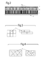
- FIG. 2 An embodiment of a containment structure in accordance with the invention is schematically illustrated in a cross-sectional view in Figure 2 .
- the structure is arranged substantially coaxially around the fan 12, the compressors 13, 14 or the turbines 16, 17 and 18.
- Uppermost in Figure 2 is most proximate to the fan etc. and hence most impact-proximate.
- the structure comprises a laminate of face sheets or septum layers 1, cellular fillings providing crushable sandwich layers 2, and a stiff backing layer 3.
- the face sheets or septum layers 1 are provided with deliberate weakenings such as perforations 1a shown in Figure 2 .
- the distributions and/or spacings and/or sizes of the perforations in the upper (impact proximate) and lower face sheets 1 in Figure 2 may be different, for example as indicated.
- the perforations 1a at each face sheet or septum layer 1 contribute to a weakening of the sandwich or laminate structure under bending. This means an impactor is freer to travel through or within the containment structure (rather than being driven down into it, with a risk of breaching the containment structure).
- the lines of perforation on the upper (impact proximate) surface may be across the line of expected ice impact and some may line up with the expected angle of blade impact.
- each face sheet or septum layer 1 may be made to optimise between trapping the impactor within the containment region provided by the containment structure, or ejecting it back into the gas path of the engine, where it can lose energy by bouncing around and impacting several times.
- the face sheets or septum layers 1 may be constituted of strips or tiles of face sheet or septum layer material for example as schematically illustrated in Figure 3 , in which abutting tiles of face sheet material are provided. The abutting regions of the tiles represent weakenings or stress raisers.
- the tile arrangements illustrated on the left and right in Figure 3 many other tile arrangements, regular or non-regular are possible in accordance with embodiments of the invention.
- the invention involves the introduction of lines or points or patterns of weakness into a containment system, entirely contrary to the expectation that the containment systems should be configured to be as strong as possible.
- the perforate or otherwise weakened face sheet or septum layer can then allow a clean entry of the released blade into the cellular layer below. Energy is removed by the crush and travel of the released blade within this cellular material.
- a layered or laminate structure comprising: a face sheet or septum layer which is provided with zones of weakness, for example by means of perforations, cuts, interruptions, dimpling, tiling; one or more crushable sandwich layers; and a stiff backing layer. It has been found that such a structure actually withstands the oblique impact of a blade or blade fragment at impact velocity better than a similar layered structure where the top layer is not provided with zones of weakness, i.e. not perforated.
- the face sheet with perforations will most likely tear as the upper part of the impactor moves across it - a face sheet without perforations will tend to drive the impactor into the containment structure and if the impactor is driven into the containment structure under the face sheet, it exerts more force onto the backing layer, and thus a thicker backing sheet is needed to resist full penetration of the containment structure.
- the inventor believes that the containment structure of the present invention, with deliberately provided weakness in the face sheet or septum layer, would allow the first impacted layer(s) to flex more, reducing the trapped wedge effect of the impactor, thereby reducing the stresses at the back surface of the backing layer 3.
- the energy of flexing is dissipated first as vibration, then as heat and possibly as plastic deformation.
- the containment system or casing construction in accordance with an embodiment of the present invention is less complicated (lower cost of manufacture), and the initial casing forging can be slimmer (because the sandwich layers 2 need not be so thick) and lighter (because the backing layer 3 need not be so thick), thus reducing the machining and material removed (and thereby providing more cost saving).
- dimples and creases in the face sheets or septum layers may be made by metal rolling using a textured roller - possibly as part of a forging process. Laser bending could be used for giving localised thick and thin regions, as well as creases or folds.
- Laser cutting could be used to give the slotted perforations. Laser cutting and bending could be performed together.
- Chemical etching could be used to provide perforations, holes or dimples or other surface contours Punching could also preferably be used.
- the present invention may find primary application in containment systems for gas turbine engines, it may also find application in other impactor or impact containment systems, for example in vehicle bumper systems, in effect to provide double protection, for low and high energy impacts.
Landscapes
- Engineering & Computer Science (AREA)
- Chemical & Material Sciences (AREA)
- Combustion & Propulsion (AREA)
- Mechanical Engineering (AREA)
- General Engineering & Computer Science (AREA)
- Laminated Bodies (AREA)
Applications Claiming Priority (1)
| Application Number | Priority Date | Filing Date | Title |
|---|---|---|---|
| GBGB0917149.7A GB0917149D0 (en) | 2009-10-01 | 2009-10-01 | Impactor containment |
Publications (2)
| Publication Number | Publication Date |
|---|---|
| EP2305961A2 true EP2305961A2 (fr) | 2011-04-06 |
| EP2305961A3 EP2305961A3 (fr) | 2017-09-13 |
Family
ID=41350607
Family Applications (1)
| Application Number | Title | Priority Date | Filing Date |
|---|---|---|---|
| EP10174256.7A Withdrawn EP2305961A3 (fr) | 2009-10-01 | 2010-08-27 | Dispositif de rétention pour projectiles |
Country Status (3)
| Country | Link |
|---|---|
| US (1) | US20110081227A1 (fr) |
| EP (1) | EP2305961A3 (fr) |
| GB (1) | GB0917149D0 (fr) |
Families Citing this family (4)
| Publication number | Priority date | Publication date | Assignee | Title |
|---|---|---|---|---|
| GB2459646B (en) * | 2008-04-28 | 2011-03-30 | Rolls Royce Plc | A fan assembly |
| US10704414B2 (en) * | 2017-03-10 | 2020-07-07 | General Electric Company | Airfoil containment structure including a notched and tapered inner shell |
| US10550718B2 (en) | 2017-03-31 | 2020-02-04 | The Boeing Company | Gas turbine engine fan blade containment systems |
| US10487684B2 (en) | 2017-03-31 | 2019-11-26 | The Boeing Company | Gas turbine engine fan blade containment systems |
Citations (1)
| Publication number | Priority date | Publication date | Assignee | Title |
|---|---|---|---|---|
| EP1245791A2 (fr) | 2001-03-30 | 2002-10-02 | ROLLS-ROYCE plc | Dispositif de rétention des aubes pour turbine à gaz |
Family Cites Families (31)
| Publication number | Priority date | Publication date | Assignee | Title |
|---|---|---|---|---|
| US3948346A (en) * | 1974-04-02 | 1976-04-06 | Mcdonnell Douglas Corporation | Multi-layered acoustic liner |
| US4149824A (en) * | 1976-12-23 | 1979-04-17 | General Electric Company | Blade containment device |
| US4934899A (en) * | 1981-12-21 | 1990-06-19 | United Technologies Corporation | Method for containing particles in a rotary machine |
| US5188505A (en) * | 1991-10-07 | 1993-02-23 | General Electric Company | Structural ring mechanism for containment housing of turbofan |
| US5205708A (en) * | 1992-02-07 | 1993-04-27 | General Electric Company | High pressure turbine component interference fit up |
| US5267828A (en) * | 1992-11-13 | 1993-12-07 | General Electric Company | Removable fan shroud panel |
| US5528904A (en) * | 1994-02-28 | 1996-06-25 | Jones; Charles R. | Coated hot gas duct liner |
| US5482429A (en) * | 1994-04-29 | 1996-01-09 | United Technologies Corporation | Fan blade containment assembly |
| US5431532A (en) * | 1994-05-20 | 1995-07-11 | General Electric Company | Blade containment system |
| US6637186B1 (en) * | 1997-11-11 | 2003-10-28 | United Technologies Corporation | Fan case liner |
| GB9812992D0 (en) * | 1998-06-17 | 1998-08-12 | Rolls Royce Plc | A gas turbine engine containment casing |
| FR2780443B1 (fr) * | 1998-06-25 | 2000-08-04 | Snecma | Anneau de stator de turbine haute pression d'une turbomachine |
| US6149380A (en) * | 1999-02-04 | 2000-11-21 | Pratt & Whitney Canada Corp. | Hardwall fan case with structured bumper |
| US6227794B1 (en) * | 1999-12-16 | 2001-05-08 | Pratt & Whitney Canada Corp. | Fan case with flexible conical ring |
| JP3632003B2 (ja) * | 2000-03-07 | 2005-03-23 | 三菱重工業株式会社 | ガスタービン分割環 |
| GB0116988D0 (en) * | 2000-08-11 | 2001-09-05 | Rolls Royce Plc | A gas turbine engine blade containment assembly |
| US6619913B2 (en) * | 2002-02-15 | 2003-09-16 | General Electric Company | Fan casing acoustic treatment |
| GB0206136D0 (en) * | 2002-03-15 | 2002-04-24 | Rolls Royce Plc | Improvements in or relating to cellular materials |
| US6695574B1 (en) * | 2002-08-21 | 2004-02-24 | Pratt & Whitney Canada Corp. | Energy absorber and deflection device |
| FR2867224B1 (fr) * | 2004-03-04 | 2006-05-19 | Snecma Moteurs | Dispositif de maintien axial de secteur d'entretoise pour anneau d'une turbine haute-pression de turbomachine |
| FR2868814B1 (fr) * | 2004-04-09 | 2009-12-18 | Snecma Moteurs | Dispositif d'assemblage de brides annulaires, en particulier dans une turbomachine |
| GB0501284D0 (en) * | 2005-01-21 | 2005-03-02 | Rolls Royce Plc | Aerofoil containment structure |
| GB2426287B (en) * | 2005-05-18 | 2007-05-30 | Rolls Royce Plc | Blade containment structure |
| DE102006036648A1 (de) * | 2006-08-03 | 2008-02-07 | Rolls-Royce Deutschland Ltd & Co Kg | Eisschlagschutzring für das Fangehäuse einer Fluggasturbine |
| GB0704879D0 (en) * | 2007-03-14 | 2007-04-18 | Rolls Royce Plc | A Casing arrangement |
| US8016543B2 (en) * | 2007-04-02 | 2011-09-13 | Michael Scott Braley | Composite case armor for jet engine fan case containment |
| GB0707099D0 (en) * | 2007-04-13 | 2007-05-23 | Rolls Royce Plc | A casing |
| US8061966B2 (en) * | 2007-12-12 | 2011-11-22 | General Electric Company | Composite containment casings |
| GB0803479D0 (en) * | 2008-02-27 | 2008-04-02 | Rolls Royce Plc | Fan track liner assembly |
| GB0813821D0 (en) * | 2008-07-29 | 2008-09-03 | Rolls Royce Plc | A fan casing for a gas turbine engine |
| US8202041B2 (en) * | 2008-10-31 | 2012-06-19 | Pratt & Whitney Canada Corp | Fan case for turbofan engine |
-
2009
- 2009-10-01 GB GBGB0917149.7A patent/GB0917149D0/en not_active Ceased
-
2010
- 2010-08-27 EP EP10174256.7A patent/EP2305961A3/fr not_active Withdrawn
- 2010-09-16 US US12/883,622 patent/US20110081227A1/en not_active Abandoned
Patent Citations (1)
| Publication number | Priority date | Publication date | Assignee | Title |
|---|---|---|---|---|
| EP1245791A2 (fr) | 2001-03-30 | 2002-10-02 | ROLLS-ROYCE plc | Dispositif de rétention des aubes pour turbine à gaz |
Also Published As
| Publication number | Publication date |
|---|---|
| EP2305961A3 (fr) | 2017-09-13 |
| GB0917149D0 (en) | 2009-11-11 |
| US20110081227A1 (en) | 2011-04-07 |
Similar Documents
| Publication | Publication Date | Title |
|---|---|---|
| EP2096269B1 (fr) | Ensemble d'enlignement de revêtements de soufflante pour moteur à turbine à gaz | |
| US8568082B2 (en) | Blade and a method for making a blade | |
| US6543991B2 (en) | Gas turbine engine blade containment assembly | |
| US6769864B2 (en) | Gas turbine engine blade containment assembly | |
| US7946827B2 (en) | Blades | |
| EP3246532B1 (fr) | Système de revêtement intérieur pour un carter de soufflante | |
| US20060269402A1 (en) | Rotor blade containment assembly for a gas turbine engine | |
| EP3640438B1 (fr) | Système de confinement de pales de soufflante | |
| EP2305961A2 (fr) | Dispositif de rétention pour projectiles | |
| GB2406615A (en) | Combined gas turbine engine blade containment assembly and acoustic treatment | |
| CN111075568B (zh) | 风扇叶片容纳系统、气体涡轮引擎和金属插入件 | |
| EP3027856B1 (fr) | Chemisage pour voie de soufflante | |
| WO2015094422A1 (fr) | Section de boîtier de confinement central de dissipation d'énergie pour turbine à gaz | |
| EP1584797A2 (fr) | Dispositif de rétention des aubes pour turbine à gaz | |
| CN111075569A (zh) | 碎屑保持 | |
| EP1715172B1 (fr) | Garniture acoustique et procédé associé de fabrication | |
| US7972116B2 (en) | Blade for a gas turbine engine | |
| JP5406528B2 (ja) | 超塑性的に形成したタービンエンジン用ブレード及びその製造方法 | |
| EP2944771B1 (fr) | Système de confinement d'hélice de soufflante dans un moteur à turbine à gaz | |
| CN113803162A (zh) | 风扇包容机匣和航空发动机 | |
| GB2447036A (en) | A containment casing | |
| EP4644669A1 (fr) | Anneau de rétention pour un moteur à turbine à gaz |
Legal Events
| Date | Code | Title | Description |
|---|---|---|---|
| PUAI | Public reference made under article 153(3) epc to a published international application that has entered the european phase |
Free format text: ORIGINAL CODE: 0009012 |
|
| AK | Designated contracting states |
Kind code of ref document: A2 Designated state(s): AL AT BE BG CH CY CZ DE DK EE ES FI FR GB GR HR HU IE IS IT LI LT LU LV MC MK MT NL NO PL PT RO SE SI SK SM TR |
|
| AX | Request for extension of the european patent |
Extension state: BA ME RS |
|
| RAP1 | Party data changed (applicant data changed or rights of an application transferred) |
Owner name: ROLLS-ROYCE PLC |
|
| PUAL | Search report despatched |
Free format text: ORIGINAL CODE: 0009013 |
|
| AK | Designated contracting states |
Kind code of ref document: A3 Designated state(s): AL AT BE BG CH CY CZ DE DK EE ES FI FR GB GR HR HU IE IS IT LI LT LU LV MC MK MT NL NO PL PT RO SE SI SK SM TR |
|
| AX | Request for extension of the european patent |
Extension state: BA ME RS |
|
| RIC1 | Information provided on ipc code assigned before grant |
Ipc: F01D 25/24 20060101ALI20170809BHEP Ipc: F02K 3/06 20060101ALI20170809BHEP Ipc: F02C 7/04 20060101ALI20170809BHEP Ipc: F01D 21/04 20060101AFI20170809BHEP |
|
| STAA | Information on the status of an ep patent application or granted ep patent |
Free format text: STATUS: THE APPLICATION HAS BEEN PUBLISHED |
|
| STAA | Information on the status of an ep patent application or granted ep patent |
Free format text: STATUS: THE APPLICATION IS DEEMED TO BE WITHDRAWN |
|
| 18D | Application deemed to be withdrawn |
Effective date: 20180314 |