EP2305977A1 - System zur Erkennung von Anomalien für Filter - Google Patents
System zur Erkennung von Anomalien für Filter Download PDFInfo
- Publication number
- EP2305977A1 EP2305977A1 EP10175859A EP10175859A EP2305977A1 EP 2305977 A1 EP2305977 A1 EP 2305977A1 EP 10175859 A EP10175859 A EP 10175859A EP 10175859 A EP10175859 A EP 10175859A EP 2305977 A1 EP2305977 A1 EP 2305977A1
- Authority
- EP
- European Patent Office
- Prior art keywords
- differential pressure
- engine
- filter
- state
- pressure pipe
- Prior art date
- Legal status (The legal status is an assumption and is not a legal conclusion. Google has not performed a legal analysis and makes no representation as to the accuracy of the status listed.)
- Granted
Links
Images




Classifications
-
- F—MECHANICAL ENGINEERING; LIGHTING; HEATING; WEAPONS; BLASTING
- F01—MACHINES OR ENGINES IN GENERAL; ENGINE PLANTS IN GENERAL; STEAM ENGINES
- F01N—GAS-FLOW SILENCERS OR EXHAUST APPARATUS FOR MACHINES OR ENGINES IN GENERAL; GAS-FLOW SILENCERS OR EXHAUST APPARATUS FOR INTERNAL-COMBUSTION ENGINES
- F01N9/00—Electrical control of exhaust gas treating apparatus
- F01N9/002—Electrical control of exhaust gas treating apparatus of filter regeneration
-
- F—MECHANICAL ENGINEERING; LIGHTING; HEATING; WEAPONS; BLASTING
- F01—MACHINES OR ENGINES IN GENERAL; ENGINE PLANTS IN GENERAL; STEAM ENGINES
- F01N—GAS-FLOW SILENCERS OR EXHAUST APPARATUS FOR MACHINES OR ENGINES IN GENERAL; GAS-FLOW SILENCERS OR EXHAUST APPARATUS FOR INTERNAL-COMBUSTION ENGINES
- F01N11/00—Monitoring or diagnostic devices for exhaust-gas treatment apparatus
- F01N11/002—Monitoring or diagnostic devices for exhaust-gas treatment apparatus the diagnostic devices measuring or estimating temperature or pressure in, or downstream of the exhaust apparatus
-
- F—MECHANICAL ENGINEERING; LIGHTING; HEATING; WEAPONS; BLASTING
- F01—MACHINES OR ENGINES IN GENERAL; ENGINE PLANTS IN GENERAL; STEAM ENGINES
- F01N—GAS-FLOW SILENCERS OR EXHAUST APPARATUS FOR MACHINES OR ENGINES IN GENERAL; GAS-FLOW SILENCERS OR EXHAUST APPARATUS FOR INTERNAL-COMBUSTION ENGINES
- F01N3/00—Exhaust or silencing apparatus having means for purifying, rendering innocuous, or otherwise treating exhaust
- F01N3/02—Exhaust or silencing apparatus having means for purifying, rendering innocuous, or otherwise treating exhaust for cooling, or for removing solid constituents of, exhaust
- F01N3/021—Exhaust or silencing apparatus having means for purifying, rendering innocuous, or otherwise treating exhaust for cooling, or for removing solid constituents of, exhaust by means of filters
- F01N3/023—Exhaust or silencing apparatus having means for purifying, rendering innocuous, or otherwise treating exhaust for cooling, or for removing solid constituents of, exhaust by means of filters using means for regenerating the filters, e.g. by burning trapped particles
- F01N3/025—Exhaust or silencing apparatus having means for purifying, rendering innocuous, or otherwise treating exhaust for cooling, or for removing solid constituents of, exhaust by means of filters using means for regenerating the filters, e.g. by burning trapped particles using fuel burner or by adding fuel to exhaust
- F01N3/0253—Exhaust or silencing apparatus having means for purifying, rendering innocuous, or otherwise treating exhaust for cooling, or for removing solid constituents of, exhaust by means of filters using means for regenerating the filters, e.g. by burning trapped particles using fuel burner or by adding fuel to exhaust adding fuel to exhaust gases
-
- F—MECHANICAL ENGINEERING; LIGHTING; HEATING; WEAPONS; BLASTING
- F01—MACHINES OR ENGINES IN GENERAL; ENGINE PLANTS IN GENERAL; STEAM ENGINES
- F01N—GAS-FLOW SILENCERS OR EXHAUST APPARATUS FOR MACHINES OR ENGINES IN GENERAL; GAS-FLOW SILENCERS OR EXHAUST APPARATUS FOR INTERNAL-COMBUSTION ENGINES
- F01N2550/00—Monitoring or diagnosing the deterioration of exhaust systems
- F01N2550/04—Filtering activity of particulate filters
-
- F—MECHANICAL ENGINEERING; LIGHTING; HEATING; WEAPONS; BLASTING
- F01—MACHINES OR ENGINES IN GENERAL; ENGINE PLANTS IN GENERAL; STEAM ENGINES
- F01N—GAS-FLOW SILENCERS OR EXHAUST APPARATUS FOR MACHINES OR ENGINES IN GENERAL; GAS-FLOW SILENCERS OR EXHAUST APPARATUS FOR INTERNAL-COMBUSTION ENGINES
- F01N2900/00—Details of electrical control or of the monitoring of the exhaust gas treating apparatus
- F01N2900/06—Parameters used for exhaust control or diagnosing
- F01N2900/16—Parameters used for exhaust control or diagnosing said parameters being related to the exhaust apparatus, e.g. particulate filter or catalyst
- F01N2900/1602—Temperature of exhaust gas apparatus
-
- Y—GENERAL TAGGING OF NEW TECHNOLOGICAL DEVELOPMENTS; GENERAL TAGGING OF CROSS-SECTIONAL TECHNOLOGIES SPANNING OVER SEVERAL SECTIONS OF THE IPC; TECHNICAL SUBJECTS COVERED BY FORMER USPC CROSS-REFERENCE ART COLLECTIONS [XRACs] AND DIGESTS
- Y02—TECHNOLOGIES OR APPLICATIONS FOR MITIGATION OR ADAPTATION AGAINST CLIMATE CHANGE
- Y02T—CLIMATE CHANGE MITIGATION TECHNOLOGIES RELATED TO TRANSPORTATION
- Y02T10/00—Road transport of goods or passengers
- Y02T10/10—Internal combustion engine [ICE] based vehicles
- Y02T10/40—Engine management systems
Definitions
- the present invention relates to an abnormality determination system for a filter that collects particulates from exhaust gases discharged from an internal combustion engine to thereby purify the exhaust gases.
- an abnormality determination system for a filter there has been known, for example, one disclosed in Japanese Laid-Open Patent Publication (Kokai) No. 2007-2694 .
- This filter is disposed in an exhaust passage, and a differential pressure pipe connects between respective portions of the exhaust passage upstream and downstream of the filter.
- the differential pressure pipe has a differential pressure sensor provided therein, for detecting the differential pressure between a pressure on the upstream side and a pressure on the downstream side of the filter.
- the abnormality determination system determines that the differential pressure pipe is in a frozen state, when the detected atmospheric air temperature is not higher than a predetermined temperature and at the same time the detected temperature of exhaust gases is not higher than a predetermined temperature.
- the abnormality determination system determines that there has occurred an abnormality in the filter. In such a case, a warning lamp is turned on to thereby warn a driver of the abnormality of the filter.
- the abnormality determination system determines that the differential pressure is not within the predetermined range not because of the abnormality of the filter but because of freezing of the differential pressure pipe, and determines that no abnormality has occurred in the filter.
- the abnormality determination system executes a failsafe action irrespective of the determination result of the frozen state of the differential pressure pipe.
- the failsafe action controls the operation of the engine such that no particulates deposited on the filter are burned, and is executed by limiting the fuel injection amount and the engine rotational speed.
- the filter is not determined to be abnormal insofar as the differential pressure pipe is determined to be in the frozen state. Therefore, even when the differential pressure pipe is not actually in the frozen state and the filter is abnormal, the filter is sometimes not determined to be abnormal. In this case, the abnormality of the filter is not notified to the driver, whereby the driver cannot take proper and quick measures against the abnormality of the filter.
- the failsafe action when the differential pressure is not within the predetermined range, the failsafe action is executed irrespective of the frozen state of the differential pressure pipe. Therefore, the failsafe action can be executed even when no abnormality has occurred in the filter. In this case, the fuel injection amount and the engine rotational speed are unnecessarily limited, which results in the degraded drivability.
- the present invention provides an abnormality determination system for a filter that is disposed in an exhaust passage for collecting particulates from exhaust gases discharged from an internal combustion engine to thereby purify the exhaust gases, including a differential pressure pipe connected between respective portions of an exhaust passage upstream and a downstream of the filter, differential pressure-detecting means disposed in the differential pressure pipe, for detecting a differential pressure between pressures on the upstream side and the downstream side of the filter, and abnormality-determining means for determining whether or not the filter is abnormal, based on the detected differential pressure, characterized by comprising specific operating state-determining means for determining whether or not the engine is in a specific operating state, frozen state-determining means for determining whether or not the differential pressure pipe is in a frozen state, based on the detected differential pressure, when the specific operating state-determining means determines that the engine is in the specific operating state, and determination inhibiting means for inhibiting the abnormality-determining means from determining that the filter is abnormal, when the frozen state-determining means determines that the differential pressure pipe is in the frozen state
- the filter collects particulates (hereinafter simply referred to as "PM" (Particulate Matter)) from exhaust gases discharged from the engine.
- the differential pressure pipe is connected to the respective portions of the exhaust passage upstream and downstream of the filter, and the differential pressure-detecting means disposed in the differential pressure pipe detects the differential pressure between the pressures on the upstream side and the downstream side of the filter. Further, it is determined whether or not the filter is abnormal, based on the differential pressure.
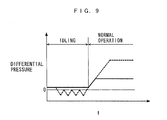
- the differential pressure has characteristics that when the differential pressure pipe is not frozen, the differential pressure between the upstream side and the downstream side of the filter takes a relatively small, approximately fixed, positive value, whereas when the differential pressure pipe is frozen, the differential pressure takes a negative value, as indicated by the broken line.
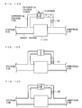
- the vehicle speed during idling of the engine is equal to 0, so that the degree of cooling of the differential pressure pipe, by wind generated by running of the vehicle, is low, and the differential pressure pipe is liable to be warmed up by exhaust gases, whereby gases trapped in a space formed by the diaphragm and ice downstream of the diaphragm expand ( FIG.
- the temperature of gases and the pressure on the downstream side of the diaphragm are in proportional relationship as can be understood from the equation of state of gas. Therefore, as the idling time period is longer, the temperature of the gases becomes higher, whereby the pressure on the downstream side of the diaphragm becomes larger. Furthermore, when the temperature of the gases become higher and the ice starts to melt, the ice moves in the differential pressure pipe toward the downstream side, and stops at a location where the differential pressure becomes approximately equal to 0 ( FIG. 10B ).
- the differential pressure has a characteristic that when the differential pressure pipe is frozen, the differential pressure takes too large a positive value, as indicated by the broken line in FIG. 9 .
- the degree of cooling of the differential pressure pipe by wind generated by running of the vehicle is high, and hence gases trapped in the space between the diaphragm and the ice shrink ( FIG. 10C ), to thereby make the pressure on the downstream side of the diaphragm negative.
- the differential pressure across the filter can exhibit different behaviors depending on the frozen state of the differential pressure pipe.
- the present invention when it is determined that the engine is in the specific operating state, it is determined whether or not the differential pressure pipe is in the frozen state, based on the detected differential pressure, and hence it is possible to properly determine the frozen state of the differential pressure pipe. Further, when it is determined that the differential pressure pipe is in the frozen state, determination that the filter is abnormal is inhibited. This makes it possible to avoid erroneous abnormality determination of the filter based on the differential pressure obtained when the differential pressure pipe is in the frozen state, thereby making it possible to improve the accuracy of the abnormality determination of the filter. Therefore, it is possible to avoid e.g. an erroneous notification to a driver based on erroneous determination that the filter is abnormal, or unnecessary limitation to the operation of the engine, whereby it is possible to improve drivability.
- the specific operating state is at least one of a state where the engine is being started and an after-run state of the engine immediately after stoppage of the engine, and when the specific operating state-determining means determines that the engine is in at least one of the state where the engine is being started and the after-run state, the frozen state-determining means determines that the differential pressure pipe is in the frozen state, when a difference between a predetermined pressure and the differential pressure is not smaller than a predetermined value.
- the differential pressure should be stable, and be equal to the predetermined pressure or take a value in the vicinity of the predetermined pressure unless the differential pressure pipe is in the frozen state.
- the specific operating state is an idling state of the engine, and when the specific operating state-determining means determines that the engine is in the idling state, the frozen state-determining means determines that the differential pressure pipe is in the frozen state, when a difference between a maximum value and a minimum value of the differential pressure in the idling state is not smaller than a predetermined value.
- the abnormality determination system further comprises regeneration operation execution means for executing a regeneration operation for regenerating the filter by causing particulates deposited on the filter to be burned, and regeneration operation forcible execution means for forcibly executing the regeneration operation for regenerating the filter separately from the regeneration operation execution means, immediately after the frozen state-determining means has determined that the differential pressure pipe is in the frozen state.
- the abnormality determination system further comprises regeneration operation-inhibiting means operable when the differential pressure pipe is determined to be in the frozen state, to inhibit the regeneration operation for regenerating the filter by the regeneration operation execution means, until the differential pressure pipe is determined not to be in the frozen state.
- the differential pressure pipe is determined to be in the frozen state, the determination that the filter is abnormal is not carried out, and therefore even when there occurs such abnormality that an excess amount of PM is deposited on the filter, determination of the abnormality is not performed.
- the operation for regenerating the filter by the regeneration operation execution means is inhibited from then on until the differential pressure pipe is determined not to be in the frozen state. This inhibits the regeneration operation even when an excess amount of PM is deposited on the filter, whereby it is possible to prevent the filter from being overheated by thermal runaway caused by sudden combustion of the excess amount of PM deposited on the filter, thereby making it possible to prevent cracking or melting of the filter.
- regeneration of the filter is forcibly performed by the regeneration operation forcible execution means immediately after the differential pressure pipe is determined to be in the frozen state, so that even if the operation for regenerating the filter by the regeneration operation execution means is inhibited until the differential pressure pipe is determined not to be in the frozen state, the amount of PM deposited on the filter can be suppressed, whereby it is possible to avoid thermal runaway caused by regeneration of the filter which is executed when the differential pressure pipe is determined not to be in the frozen state.
- the abnormality determination system further comprises torque-limiting means operable when the differential pressure pipe is determined to be in the frozen state, to limit torque of the engine until the differential pressure pipe is determined not to be in the frozen state.
- the abnormality determination system further comprises engine off time-acquiring means for acquiring engine off time before the engine is started, and in a case where the frozen state-determining means has determined that the differential pressure pipe is in the frozen state, the frozen state-determining means determines that the differential pressure pipe has been released from the frozen state, when the acquired engine off time is longer than a predetermined time period and at the same time a difference between a predetermined pressure and the differential pressure is smaller than a predetermined value when the engine is being started thereafter.
- engine off time-acquiring means for acquiring engine off time before the engine is started, and in a case where the frozen state-determining means has determined that the differential pressure pipe is in the frozen state, the frozen state-determining means determines that the differential pressure pipe has been released from the frozen state, when the acquired engine off time is longer than a predetermined time period and at the same time a difference between a predetermined pressure and the differential pressure is smaller than a predetermined value when the engine is being started thereafter.
- the differential pressure pipe in a case where it has been determined that the differential pressure pipe is in the frozen state, if the acquired engine off time is longer than the predetermined time period and at the same time the difference between the predetermined pressure and the differential pressure is smaller than the predetermined value when the engine is being started thereafter, it is determined that the differential pressure pipe is released from the frozen state. This makes it possible to properly cancel the determination that the differential pressure pipe is in the frozen state while eliminating influence of the temperature of the filter and its neighborhood on the differential pressure.
- FIG. 1 schematically shows an abnormality determination system 1 according to an embodiment of the present invention, and an internal combustion engine (hereinafter referred to as the "engine") 3 to which is applied the abnormality determination system 1.
- the engine 3 is a diesel engine that has e.g. four cylinders, and is installed on a vehicle (not shown).
- a cylinder head 3a of the engine 3 has a fuel injection valve (hereinafter referred to as the "injector") 4 mounted therethrough for each associated cylinder such that the injector 4 faces a combustion chamber 3b of the associated cylinder.
- the valve-opening time period and the valve-opening timing of the injector 4 are controlled by a drive signal from an ECU 2, whereby a fuel injection amount QINJ and fuel injection timing are controlled.
- An intake passage 5 of the engine 3 is provided with an intake air temperature sensor 21.
- the intake air temperature sensor 21 detects a temperature TA within the intake passage 5 (hereinafter referred to as the "intake air temperature TA"), and delivers a detection signal indicative of the detected intake air temperature TA to the ECU 2.
- crank angle sensor 22 delivers a CRK signal and a TDC signal, which are both pulse signals, to the ECU 2 along with rotation of a crankshaft 3c.
- Each pulse of the CRK signal is generated whenever the crankshaft 3c rotates through a predetermined crank angle (e.g. 30° ).
- the ECU 2 calculates a rotational speed NE of the engine 3 (hereinafter referred to as the "engine speed NE") based on the CRK signal.
- the TDC signal indicates that a piston 3d of one of the cylinders of the engine 3 is in a predetermined crank angle position slightly before the TDC position at the start of the intake stroke. In the case of the four-cylinder engine 3 of the present embodiment, the TDC signal is delivered whenever the crankshaft 3c rotates through 180° .
- An oxidation catalyst 7 and a filter 8 are provided at respective locations of an exhaust passage 6 from upstream to downstream in the mentioned order.
- the oxidation catalyst 7 is formed of a metal honeycomb core (not shown) carrying a zeolite (not shown) on the surface thereof.
- the zeolite has a characteristic that it traps hydrocarbons (hereinafter referred to as "HC").
- HC hydrocarbons
- the filter 8 has a honeycomb core (not shown) formed e.g. of a porous ceramic, and is configured such that it collects PM, such as soot, from exhaust gases to thereby reduce the amount of PM emitted into the air. Further, when the temperature of the filter 8 is not lower than a predetermined temperature, PM deposited on the filter 8 is burned, whereby the filter 8 is regenerated.
- a honeycomb core not shown
- PM such as soot
- the exhaust passage 6 has a differential pressure pipe 6a connected thereto which connects between a portion of the exhaust passage 6 between the oxidation catalyst 7 and the filter 8, and a portion of the same downstream of the filter 8 in a manner bypassing the filter 8.
- the differential pressure pipe 6a is provided with a differential pressure sensor 23.
- the differential pressure sensor 23 is of a diaphragm type which has a diaphragm 23b for partitioning a differential pressure chamber 23a into upstream and downstream sections, and is configured to detect a differential pressure DP in the exhaust passage 6 between the upstream side and the downstream side of the filter 8, to deliver a detection signal indicative of the detected differential pressure to the ECU 2.
- Delivered to the ECU 2 are a detection signal indicative of a stepped-on amount AP of an accelerator pedal (not shown) of the vehicle (hereinafter referred to as the "accelerator pedal opening AP") from an accelerator pedal opening sensor 24, and a detection signal indicative of a vehicle speed VP from a vehicle speed sensor 25. Further, a warning lamp 26 for warning a driver that the filter 8 is abnormal is connected to the ECU 2.
- the ECU 2 is implemented by a microcomputer comprised of a CPU, a RAM, a ROM, and an I/O interface (none of which are specifically shown). Further, the ECU 2 includes first and second timers 2a and 2b of an up-count type.
- the ECU 2 determines operating conditions of the engine 3 based on the detection signals from the aforementioned sensors 21 to 25, and depending on the determined operating conditions of the engine 3, performs control processes, such as a fuel injection control process for controlling the fuel injection amount QINJ and the fuel injection timing.
- the fuel injection amount QINJ and the fuel injection timing are calculated by searching respective predetermined maps (none of which are specifically shown) according to the engine speed NE and a demanded torque PMCMD.
- the demanded torque PMCMD is calculated by searching a predetermined map (not shown) according to the engine speed NE and the accelerator pedal opening AP.
- the ECU 2 executes an abnormality determination process for the filter 8, and regeneration control for controlling a regeneration operation for regenerating the filter 8.
- the ECU 2 corresponds to abnormality-determining means, specific operating state-determining means, frozen state-determining means, determination inhibiting means, regeneration operation execution means, regeneration operation forcible execution means, regeneration operation-inhibiting means, and torque-limiting means.
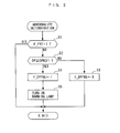
- FIG. 2 is a flowchart of a process for determining abnormality of the above-mentioned filter 8.
- the present process is carried out in synchronism with generation of the TDC signal.
- a step 1 shown as "S1" in abbreviated form in FIG. 2 ; the following steps are also shown in abbreviated form
- F_FRZ a frozen state-indicative flag
- the frozen state-indicative flag F_FRZ is set to 1 when it is determined that the differential pressure pipe 6a is in a frozen state.
- the process for determining a frozen state of the differential pressure pipe 6a will be described hereinafter.
- step 2 If the answer to this question is negative (NO), i.e. if it is determined that the differential pressure pipe 6a is not in the frozen state, it is determined whether or not the differential pressure DP detected by the differential pressure sensor 23 is not smaller than a first predetermined pressure DPREF1 (step 2). If the answer to this question is negative (NO), it is judged that the filter 8 is normal since no excess amount of PM is deposited on the filter 8, and to indicate this fact, an abnormality flag F_DPFNG is set to 0 (step 3), followed by terminating the present process.
- the abnormality flag F_DPFNG is set to 1 (step 4).
- the warning lamp 26 is turned on (step 5), followed by terminating the present process.
- the warning lamp 26 is turned on to warn the driver that an excess amount of PM has been deposited on the filter 8, and prompt the driver to bring the vehicle e.g. to a factory so as to avoid thermal runaway caused by combustion of PM in the state of the excess amount of PM being deposited on the filter 8.
- the present process is immediately terminated without determining the abnormality of the filter 8.
- FIG. 3 is a subroutine of the above-mentioned process for determining a frozen state of the differential pressure pipe 6a.
- the after-run flag F_AFT is set to 1 in an after-run state of the engine 3.
- the after-run state is a state of the engine 3 corresponding to a time period after turning off an ignition switch (not shown), during which the engine speed NE is equal to 0 and running information of the vehicle before turning off the ignition switch is being written in the ECU 2.
- step 12 If the answer to the question of the step 11 is affirmative (YES), i.e. if the engine 3 is in the after-run state, it is determined whether or not an environmental condition flag F_ENV is equal to 1 (step 12).
- the environmental condition flag F_ENV is set to 1 when environmental conditions for performing determination of the frozen state of the differential pressure pipe 6a are satisfied. A process for determining whether the environmental conditions are satisfied will be described hereinafter.
- step 12 If the answer to the question of the step 12 is negative (NO), i.e. if the environmental conditions for determining the frozen state of the differential pressure pipe 6a are not satisfied, the present process is immediately terminated without determining the frozen state.
- a first timer value TM1 of the first timer 2a is not smaller than a first predetermined time period TREF1 (e.g. 0.3 to 0.5 sec.) (step 13).
- the first timer value TM1 is reset to 0 at the start of the after run.
- step 13 If the answer to the question of the step 13 is negative (NO), i.e. if the first predetermined time period TREF1 has not elapsed after the start of the after run, it is judged that the differential pressure across the filter 8 is not stable, and the present process is immediately terminated without determining the frozen state.
- step 14 it is judged that the differential pressure has been stabilized, and it is determined whether or not the absolute value
- the second predetermined pressure DPREF2 corresponds to a differential pressure which should be obtained when the filter 8 is normal and the differential pressure pipe 6a is not frozen.
- the differential pressure DP in the after-run state of the engine 3, if the differential pressure DP is stable and the differential pressure pipe 6a is not frozen, it should take a value in the vicinity of the second predetermined pressure DPREF2. Therefore, if the answer to the question of the step 14 is affirmative (YES), and
- step 11 determines whether or not the frozen state-indicative flag F_FRZ is equal to 1 (step 16). If the answer to this question is negative (NO), the present process is terminated.
- step 16 determines whether or not the absolute value of the difference between the second predetermined pressure DPREF2 and the differential pressure DP is not smaller than the predetermined value DREF. If the answer to this question is affirmative (YES), it is judged that the differential pressure pipe 6a continues to be in the frozen state, and the process proceeds to the step 15, wherein the frozen state-indicative flag F_FRZ is set to 1, followed by terminating the present process.
- step 14 determines whether or not the ignition switch (IGSW) is turned on between the immediately preceding loop and the present loop (step 17). If the answer to this question is negative (NO), the present process is terminated.
- IGSW ignition switch
- step 18 if the answer to the question of the step 17 is affirmative (YES), i.e. if it is immediately after the ignition switch has been turned on, it is determined whether or not a second timer value TM2 of the second timer 2b is larger than a second predetermined time period TREF2 (e.g. 6 to 7 hours) (step 18).
- the second timer value TM2 is configured such that it is reset to 0 when the ignition switch is turned off. Therefore, the second timer value TM2 obtained immediately after turning on of the ignition switch represents engine off time before the engine 3 is started. If the answer to the question of the step 18 is negative (NO), i.e. if the engine off time is not longer than the second predetermined time period TREF2, the present process is terminated.
- step 18 if the answer to the question of the step 18 is affirmative (YES), i.e. if the engine off time is longer than the second predetermined time period TREF2, it is judged that the differential pressure pipe 6a has been released from the frozen state, and to indicate this fact, the frozen state-indicative flag F_FRZ is set to 0 (step 19), followed by terminating the present process.
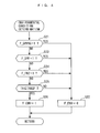
- FIG. 4 is a subroutine of the above-mentioned process for determining whether the environmental conditions are satisfied.
- the abnormality flag F_DPFNG set in the aforementioned step 3 or 4 is equal to 1. If the answer to this question is affirmative (YES), it is judged that the environmental conditions for determining the frozen state of the differential pressure pipe 6a are not satisfied since the filter 8 is determined to be abnormal, and to indicate this fact, the environmental condition flag F_ENV is set to 0 (step 22), followed by terminating the present process.
- step 23 it is determined whether or not a regeneration flag F_DPF is equal to 1 (step 23).
- the regeneration flag F_DPF is set to 1 during execution of a normal regeneration operation, referred to hereinafter, for regenerating the filter 8. If the answer to this question is affirmative (YES), i.e. if the normal regeneration operation for regenerating the filter 8 is being executed, there is a fear that the differential pressure DP is not stable in accordance with the execution of the normal regeneration operation, so that it is judged that the environmental conditions are not satisfied, and the above-mentioned step 22 is executed to set the environmental condition flag F_ENV to 0, followed by terminating the present process.
- step 24 it is determined whether or not the frozen state-indicative flag F_FRZ is equal to 1 (step 24). If the answer to this question is affirmative (YES), it is judged that the differential pressure pipe 6a has already been frozen, and the environmental conditions are not satisfied, and the above-mentioned step 22 is executed, followed by terminating the present process.
- step 24 determines whether or not the intake air temperature TA is not higher than a predetermined temperature TAREF (e.g. - 20 °C) (step 25). If the answer to this question is negative (NO), it is judged that the environmental conditions are not satisfied since there is a low possibility that the differential pressure pipe 6a is frozen, and it is unnecessary to determine the frozen state of the differential pressure pipe 6a, and the aforementioned step 22 is executed, followed by terminating the present process.
- a predetermined temperature TAREF e.g. - 20 °C
- the environmental condition flag F_ENV is set to 1 (step 26), followed by terminating the present process.
- FIG. 5 is a flowchart of a process for the above-mentioned regeneration control for controlling the regeneration operation for regenerating the filter 8.
- the present process is carried out in synchronism with generation of the TDC signal.
- a step 31 it is determined whether or not the frozen state-indicative flag F_FRZ is equal to 1. If the answer to this question is negative (NO), i.e. if it is determined that the differential pressure pipe 6a is not in the frozen state, normal regeneration control is carried out (step 32), followed by terminating the present process.
- the normal regeneration control is carried out as follows: First, the amount of PM emitted from the engine 3 (PM emission amount) is calculated by searching a predetermined map (not shown) according to the engine speed NE and the fuel injection amount QINJ. Next, the PM emission amount is added to the amount of PM deposited on the filter 8 (PM deposition amount) calculated hitherto to thereby calculate the present PM deposition amount MSOOT. Then, when the value of the PM deposition amount is not smaller than a predetermined value, not only normal fuel injection but also additional fuel injection is performed, whereby the normal regeneration operation is executed. Further, the normal regeneration operation is terminated when a value obtained by subtracting the amount of PM burned along with the regeneration operation from the PM deposition amount becomes approximately equal to 0.
- step 33 it is determined whether or not the PM deposition amount MSOOT is not smaller than a predetermined value MSOOTREF (step 33). If the answer to this question is affirmative (YES), it is determined whether or not the frozen state-indicative flag F_FRZ has been changed from 0 to 1 between the immediately preceding loop and the present loop (step 34). If the answer to this question is affirmative (YES), i.e. if it is immediately after the differential pressure pipe 6a is determined to be in the frozen state, it is judged that a forced regeneration operation for regenerating the filter 8 is to be executed. Then, a forcible regeneration flag F_DPFC is set to 1 (step 35), and the forced regeneration operation is executed (step 36), followed by terminating the present process.
- a forcible regeneration flag F_DPFC is set to 1 (step 35), and the forced regeneration operation is executed (step 36), followed by terminating the present process.
- step 34 determines whether or not the forcible regeneration flag F_DPFC is equal to 1 (step 37). If the answer to this question is affirmative (YES), the process proceeds to the aforementioned step 36, wherein the forced regeneration operation is continued.
- the answer to the question of the step 33 becomes negative (NO).
- the forcible regeneration flag F_DPFC is set to 0 (step 40), and then the process proceeds to the above-mentioned step 37.
- the answer to the question of the step 37 becomes negative (NO), and in this case, it is determined whether or not the demanded torque PMCMD is not smaller than an upper limit value PMLMT (step 38).
- the differential pressure pipe 6a is in the frozen state, and therefore it is possible to properly determine the frozen state based on the differential pressure DP in the stable state.
- the abnormality determination of the filter 8 based on the differential pressure DP is inhibited (YES to the step 1), so that it is possible to avoid erroneous abnormality determination of the filter 8 based on the differential pressure DP that is obtained when the differential pressure pipe 6a is in the frozen state.
- the normal regeneration operation is inhibited before the differential pressure pipe 6a is determined not to be in the frozen state and hence even when an excess amount of PM is deposited on the filter 8, it is possible to prevent the filter 8 from being overheated by thermal runaway caused by sudden combustion of the excess amount of PM deposited on the filter 8, thereby making it possible to prevent cracking or melting of the filter 8.
- the forced regeneration operation for regenerating the filter 8 is carried out (step 35), so that the PM deposition amount MSOOT can be made approximately equal to 0, whereby even when the frozen state of the differential pressure pipe 6a continues for a long time period, it is possible to suppress the PM deposition amount MSOOT deposited along with the subsequent operation of the engine 3.
- the PM deposition amount MSOOT deposited on the filter 8 can be suppressed, whereby it is possible to avoid thermal runaway caused by the normal regeneration operation executed when the differential pressure pipe 6a is determined not to be in the frozen state.
- the demanded torque PMCMD is limited (steps 38 and 39), and accordingly the fuel injection amount QINJ is limited, whereby it is possible to prevent a rise in the temperature of exhaust gases, which makes it possible to prevent natural combustion of PM.
- the fuel injection amount QINJ is limited, whereby it is possible to prevent a rise in the temperature of exhaust gases, which makes it possible to prevent natural combustion of PM.
- an excess amount of PM is deposited on the filter 8, it is possible to prevent thermal runaway from being caused by natural combustion of the PM.
- the differential pressure pipe 6a is released from the frozen state, when the second timer value TM2, which is engine off time before the engine 3 is started, is longer than the second predetermined time period TREF2, and at the same time the absolute value (
- the second timer value TM2 which is engine off time before the engine 3 is started
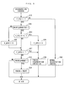
- FIG. 6 shows a variation of the process for determining a frozen state of the differential pressure pipe 6a.
- component elements and steps identical to those referred to in the process shown in FIG. 3 are denoted by the same reference numerals, and detailed description thereof is omitted.
- the present process first, in the step 12, it is determined whether or not the environmental condition flag F_ENV is equal to 1. If the answer to this question is negative (NO), it is judged that the environmental conditions for determining the frozen state of the differential pressure pipe 6a are not satisfied, and the present process is immediately terminated without determining the frozen state.
- step 41 it is determined whether or not an idling flag F_IDL is equal to 1 (step 41).
- the idling flag F_IDL is set to 1 when it is determined that the engine 3 is idling. A process for determining idling of the engine 3 will be described hereinafter.
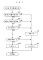
- FIG. 7 is a subroutine of the above-mentioned process for determining idling of the engine 3.
- the engine speed NE is between a predetermined lower limit value NEIDLL and a predetermined upper limit value NEIDLH, whether or not the fuel injection amount QINJ is between a predetermined lower limit value QINJL and a predetermined upper limit value QINJH, and whether or not the vehicle speed VP is smaller than a predetermined value VPREF, respectively. If any of the answers to these questions is negative (NO), a third timer value TM3 of a third timer (not shown) of an up-count type is reset to 0 (step 56). Then, it is judged that the engine 3 is not idling, and the idling flag F_IDL is set to 0 (step 57), followed by terminating the present process.
- step 54 it is determined whether or not the third timer value TM3 is not smaller than a third predetermined time period TREF3 (step 54). If the answer to this question is negative (NO), the above-mentioned step 57 is executed, followed by terminating the present process.
- step 54 if the answer to the question of the step 54 is affirmative (YES), i.e. if the conditions of the steps 51 to 53 are continuously satisfied for the third predetermined time period TREF3 or longer, it is judged that the engine 3 is idling, and the idling flag F_IDL is set to 1 (step 55), followed by terminating the present process.
- FIG. 8 is a subroutine of the above-mentioned process for calculating the maximum value DPMAX and the minimum value DPMIN of the differential pressure DP.
- the present process first, in a step 61, it is determined whether or not the idling flag F_IDL is equal to 1. If the answer to this question is negative (NO), a fourth timer value TM4 of a fourth timer (not shown) of an up-count type is reset to 0 (step 67), followed by terminating the present process.
- step 61 determines whether or not the fourth timer value TM4 is not larger than a fourth predetermined time period TREF4 (step 62). If the answer to this question is affirmative (YES), it is determined whether or not the differential pressure DP is larger than the maximum value DPMAX (step 63).
- the maximum value DPMAX is initialized to a predetermined negative value at the start of idling. If the answer to the question of the step 63 is negative (NO), i.e. if DP ⁇ DPMAX holds, the process proceeds to a step 65, referred to hereinafter.
- step 64 the differential pressure DP is set as the maximum value DPMAX (step 64), whereby the maximum value DPMAX is updated, and the process proceeding to the step 65.
- the step 65 it is determined whether or not the differential pressure DP is smaller than the minimum value DPMIN.
- the minimum value DPMIN is initialized to a predetermined positive value at the start of idling. If the answer to the question of the step 65 is negative (NO), i.e. if DP ⁇ DPMIN holds, the present process is immediately terminated.
- the differential pressure DP is set as the minimum value DPMIN (step 66), whereby the minimum value DPMIN is updated, followed by terminating the present process.
- step 62 determines whether the answer to the question of the step 62 is negative (NO), i.e. if the fourth predetermined time period TREF4 has elapsed after the start of idling.
- the process proceeds to the above-mentioned step 65 without calculating the maximum value DPMAX, wherein the minimum value DPMIN is calculated, followed by terminating the present process.
- the present invention is by no means limited to the embodiment described above, but it can be practiced in various forms.
- the after-run state or the idling state is set as a specific operating state of the engine 3 for determining the frozen state of the differential pressure pipe 6a, this is not limitative, but another operating state in which the behavior of the differential pressure is clearly different between the frozen state and the unfrozen state of the differential pressure pipe may be set as the specific operating state.
- determination of whether or not the differential pressure pipe 6a is in the frozen state is performed in the after-run state of the engine 3, based on the difference between the second predetermined pressure DPREF2 and the differential pressure DP, this is not limitative, but instead of this or in combination with this, the determination may be performed in a state where the engine 3 is being started.
- the term "state where the engine 3 is being started” is intended to mean a state of the engine 3 after the ignition switch is turned on and before cranking of the engine 3 is started or a state where the engine 3 is being cranked.
- the very abnormality determination of the filter 8 is inhibited, this is not limitative, but it is only required to inhibit determination that the filter 8 is abnormal, when the differential pressure pipe 6a is determined to be in the frozen state.
- the determination that the filter 8 is abnormal may be suspended while the abnormality determination of the filter 8 is performed.
- differential pressure DP across the filter 8 is detected by the single differential pressure sensor 23
- respective pressures on the upstream side and the downstream side of the filter 8 may be detected using respective separate sensors, to thereby calculate the differential pressure DP based on the detection values of the pressures.
- the present invention is applied to a diesel engine installed on a vehicle, by way of example, this is not limitative, but the present invention may be applied to various types of engines, such as a gasoline engine, other than the diesel engine. Further, the present invention can also be applied to engines other than engines for vehicles, including engines for ship propulsion machines, such as an outboard motor having a vertically-disposed crankshaft.
- An abnormality determination system for a filter which is capable of properly determining the frozen state of a differential pressure pipe to thereby improve the accuracy of abnormality determination of the filter.
- the abnormality determination system for the filter determines whether or not the filter is abnormal, based on the detected differential pressure between pressures on the upstream side and the downstream side of the filter. Further, if it is determined that an internal combustion engine is in a specific operating state, the abnormality determination system determines whether or not a differential pressure pipe is in a frozen state, based on the detected differential pressure, and if it is determined that the differential pressure pipe in the frozen state, the abnormality determination system inhibits determination that the filter is abnormal.
Landscapes
- Engineering & Computer Science (AREA)
- Chemical & Material Sciences (AREA)
- Combustion & Propulsion (AREA)
- Mechanical Engineering (AREA)
- General Engineering & Computer Science (AREA)
- Chemical Kinetics & Catalysis (AREA)
- Processes For Solid Components From Exhaust (AREA)
Applications Claiming Priority (1)
| Application Number | Priority Date | Filing Date | Title |
|---|---|---|---|
| JP2009219684A JP4967006B2 (ja) | 2009-09-24 | 2009-09-24 | フィルタの異常判定装置 |
Publications (2)
| Publication Number | Publication Date |
|---|---|
| EP2305977A1 true EP2305977A1 (de) | 2011-04-06 |
| EP2305977B1 EP2305977B1 (de) | 2012-06-06 |
Family
ID=42983435
Family Applications (1)
| Application Number | Title | Priority Date | Filing Date |
|---|---|---|---|
| EP10175859A Not-in-force EP2305977B1 (de) | 2009-09-24 | 2010-09-08 | System zur Erkennung von Anomalien für Filter |
Country Status (2)
| Country | Link |
|---|---|
| EP (1) | EP2305977B1 (de) |
| JP (1) | JP4967006B2 (de) |
Cited By (6)
| Publication number | Priority date | Publication date | Assignee | Title |
|---|---|---|---|---|
| US9389146B2 (en) | 2014-02-26 | 2016-07-12 | Komatsu Ltd. | Malfunction-determining device for exhaust gas purifying device and malfunction-determining method for exhaust gas purifying device |
| WO2016190890A1 (en) | 2015-05-28 | 2016-12-01 | Cummins Inc. | System and method to detect and respond to iced sensors in exhaust after-treatment system |
| FR3098248A1 (fr) * | 2019-07-03 | 2021-01-08 | Psa Automobiles Sa | Procede de diagnostic de presence de gel dans un piquage d'un capteur de pression differentielle |
| WO2021058250A1 (de) * | 2019-09-26 | 2021-04-01 | Vitesco Technologies GmbH | Verfahren und vorrichtung zur ermittlung des vereisungszustands einer nicht direkt im abgasmassenfluss angeordneten komponente des abgasstrangs eines kraftfahrzeugs |
| US11002173B2 (en) | 2019-03-05 | 2021-05-11 | Subaru Corporation | Freezing diagnosing device and engine control apparatus |
| CN113775398A (zh) * | 2021-10-15 | 2021-12-10 | 潍柴动力股份有限公司 | 一种柴油机颗粒捕集器的控制方法、装置、单元和车辆 |
Families Citing this family (2)
| Publication number | Priority date | Publication date | Assignee | Title |
|---|---|---|---|---|
| JP5791313B2 (ja) * | 2011-03-08 | 2015-10-07 | 本田技研工業株式会社 | フィルタの異常判定装置 |
| JP6120825B2 (ja) | 2014-12-25 | 2017-04-26 | 本田技研工業株式会社 | 内燃機関の排気浄化装置 |
Citations (4)
| Publication number | Priority date | Publication date | Assignee | Title |
|---|---|---|---|---|
| EP1602806A1 (de) * | 2004-06-03 | 2005-12-07 | Denso Corporation | Einrichtung zur Regelung der Abgasemissionen einer Brennkraftmaschine |
| US20060254265A1 (en) * | 2005-05-11 | 2006-11-16 | Honda Motor Co., Ltd. | Exhaust gas purifying apparatus for internal combustion engine |
| JP2007002694A (ja) | 2005-06-22 | 2007-01-11 | Honda Motor Co Ltd | 内燃機関の排気浄化装置 |
| EP1942262A2 (de) * | 2006-12-26 | 2008-07-09 | Toyota Jidosha Kabushiki Kaisha | Abgasreinigungsvorrichtung und Verfahren für Verbrennungsmotoren |
Family Cites Families (4)
| Publication number | Priority date | Publication date | Assignee | Title |
|---|---|---|---|---|
| JP2881075B2 (ja) * | 1992-08-05 | 1999-04-12 | 三菱電機株式会社 | 排気還流制御装置の故障診断方法 |
| JP4363211B2 (ja) * | 2004-02-12 | 2009-11-11 | 株式会社デンソー | 内燃機関の排気浄化装置の異常検出装置 |
| JP2006009598A (ja) * | 2004-06-22 | 2006-01-12 | Denso Corp | 燃料噴射装置 |
| JP2008215535A (ja) * | 2007-03-06 | 2008-09-18 | Toyota Motor Corp | ディーゼル車の制御装置 |
-
2009
- 2009-09-24 JP JP2009219684A patent/JP4967006B2/ja active Active
-
2010
- 2010-09-08 EP EP10175859A patent/EP2305977B1/de not_active Not-in-force
Patent Citations (4)
| Publication number | Priority date | Publication date | Assignee | Title |
|---|---|---|---|---|
| EP1602806A1 (de) * | 2004-06-03 | 2005-12-07 | Denso Corporation | Einrichtung zur Regelung der Abgasemissionen einer Brennkraftmaschine |
| US20060254265A1 (en) * | 2005-05-11 | 2006-11-16 | Honda Motor Co., Ltd. | Exhaust gas purifying apparatus for internal combustion engine |
| JP2007002694A (ja) | 2005-06-22 | 2007-01-11 | Honda Motor Co Ltd | 内燃機関の排気浄化装置 |
| EP1942262A2 (de) * | 2006-12-26 | 2008-07-09 | Toyota Jidosha Kabushiki Kaisha | Abgasreinigungsvorrichtung und Verfahren für Verbrennungsmotoren |
Cited By (14)
| Publication number | Priority date | Publication date | Assignee | Title |
|---|---|---|---|---|
| US9389146B2 (en) | 2014-02-26 | 2016-07-12 | Komatsu Ltd. | Malfunction-determining device for exhaust gas purifying device and malfunction-determining method for exhaust gas purifying device |
| WO2016190890A1 (en) | 2015-05-28 | 2016-12-01 | Cummins Inc. | System and method to detect and respond to iced sensors in exhaust after-treatment system |
| EP3303784A4 (de) * | 2015-05-28 | 2018-06-13 | Cummins, Inc. | System und verfahren zur erkennung und reaktion auf gefrorene sensoren in einem abgasnachbehandlungssystem |
| US10408111B2 (en) | 2015-05-28 | 2019-09-10 | Cummins Inc. | System and method to detect and respond to iced sensors in exhaust after-treatment system |
| EP3660286A1 (de) | 2015-05-28 | 2020-06-03 | Cummins, Inc. | System und verfahren zur erkennung und reaktion auf gefrorene sensoren in einem abgasnachbehandlungssystem |
| CN111677575A (zh) * | 2015-05-28 | 2020-09-18 | 康明斯公司 | 燃烧系统、操作该系统的方法和用于该系统的控制模块 |
| US11002173B2 (en) | 2019-03-05 | 2021-05-11 | Subaru Corporation | Freezing diagnosing device and engine control apparatus |
| FR3098248A1 (fr) * | 2019-07-03 | 2021-01-08 | Psa Automobiles Sa | Procede de diagnostic de presence de gel dans un piquage d'un capteur de pression differentielle |
| WO2021058250A1 (de) * | 2019-09-26 | 2021-04-01 | Vitesco Technologies GmbH | Verfahren und vorrichtung zur ermittlung des vereisungszustands einer nicht direkt im abgasmassenfluss angeordneten komponente des abgasstrangs eines kraftfahrzeugs |
| CN114402132A (zh) * | 2019-09-26 | 2022-04-26 | 纬湃科技有限责任公司 | 用于查明机动车的排气系的非直接布置在废气质量流中的组件的结冰状态的方法和装置 |
| KR20220064403A (ko) * | 2019-09-26 | 2022-05-18 | 비테스코 테크놀로지스 게엠베하 | 배기가스 질량 흐름에 직접 배치되지 않은 자동차 배기가스 시스템의 부품의 결빙 상태를 결정하기 위한 방법 및 디바이스 |
| CN114402132B (zh) * | 2019-09-26 | 2024-04-30 | 纬湃科技有限责任公司 | 用于查明机动车的排气系的非直接布置在废气质量流中的组件的结冰状态的方法和装置 |
| KR102730566B1 (ko) | 2019-09-26 | 2024-11-15 | 비테스코 테크놀로지스 게엠베하 | 배기가스 질량 흐름에 직접 배치되지 않은 자동차 배기가스 시스템의 부품의 결빙 상태를 결정하기 위한 방법 및 디바이스 |
| CN113775398A (zh) * | 2021-10-15 | 2021-12-10 | 潍柴动力股份有限公司 | 一种柴油机颗粒捕集器的控制方法、装置、单元和车辆 |
Also Published As
| Publication number | Publication date |
|---|---|
| JP2011069259A (ja) | 2011-04-07 |
| EP2305977B1 (de) | 2012-06-06 |
| JP4967006B2 (ja) | 2012-07-04 |
Similar Documents
| Publication | Publication Date | Title |
|---|---|---|
| EP2305977B1 (de) | System zur Erkennung von Anomalien für Filter | |
| JP4253294B2 (ja) | エンジンの自己診断装置 | |
| US7404291B2 (en) | Exhaust gas purifying apparatus for internal combustion engine | |
| GB2536947A (en) | Method and system for diagnosing efficiency of an aftertreatment system of an internal combustion engine | |
| EP2309111B1 (de) | Vorrichtung zur Erkennung von Anomalien für Turbolader | |
| JP2007170360A (ja) | 内燃機関の排気浄化装置 | |
| JP5791313B2 (ja) | フィルタの異常判定装置 | |
| US7331171B2 (en) | Control system and method for internal combustion engine | |
| EP1722082B1 (de) | System zur Regelung der Abgasemissionen einer Brennkraftmaschine und Regelungsverfahren | |
| EP2322776B1 (de) | Abgasreinigungssystem für einen Verbrennungsmotor | |
| EP1890027B1 (de) | Abgasemissionssteuerungsystem und verfahren für einen Verbrennungsmotor | |
| JP4496126B2 (ja) | 内燃機関の排ガス浄化装置 | |
| JP2006316746A (ja) | 内燃機関の排ガス浄化装置 | |
| JP6254411B2 (ja) | エンジンの制御装置 | |
| JP4247843B2 (ja) | 温度検出装置の異常判定装置 | |
| JP2020023904A (ja) | 内燃機関の制御装置 | |
| JP5366015B2 (ja) | 内燃機関の排気浄化装置 | |
| JP2019116876A (ja) | センサ診断システム | |
| US20170370317A1 (en) | Abnormality diagnosis device for pm sensor | |
| JP7389726B2 (ja) | 再生制御装置および再生制御方法 | |
| JP2025085320A (ja) | 内燃機関の排気浄化システムの凍結診断装置 | |
| JP3796927B2 (ja) | 内燃機関の還元剤供給制御装置 | |
| JP2006316734A (ja) | 内燃機関の排ガス浄化装置 | |
| JP2025145317A (ja) | 車両診断装置 | |
| JP2005315091A (ja) | 内燃機関の制御装置 |
Legal Events
| Date | Code | Title | Description |
|---|---|---|---|
| PUAI | Public reference made under article 153(3) epc to a published international application that has entered the european phase |
Free format text: ORIGINAL CODE: 0009012 |
|
| 17P | Request for examination filed |
Effective date: 20100908 |
|
| AK | Designated contracting states |
Kind code of ref document: A1 Designated state(s): AL AT BE BG CH CY CZ DE DK EE ES FI FR GB GR HR HU IE IS IT LI LT LU LV MC MK MT NL NO PL PT RO SE SI SK SM TR |
|
| AX | Request for extension of the european patent |
Extension state: BA ME RS |
|
| GRAP | Despatch of communication of intention to grant a patent |
Free format text: ORIGINAL CODE: EPIDOSNIGR1 |
|
| GRAS | Grant fee paid |
Free format text: ORIGINAL CODE: EPIDOSNIGR3 |
|
| GRAA | (expected) grant |
Free format text: ORIGINAL CODE: 0009210 |
|
| AK | Designated contracting states |
Kind code of ref document: B1 Designated state(s): AL AT BE BG CH CY CZ DE DK EE ES FI FR GB GR HR HU IE IS IT LI LT LU LV MC MK MT NL NO PL PT RO SE SI SK SM TR |
|
| REG | Reference to a national code |
Ref country code: GB Ref legal event code: FG4D |
|
| REG | Reference to a national code |
Ref country code: AT Ref legal event code: REF Ref document number: 561157 Country of ref document: AT Kind code of ref document: T Effective date: 20120615 Ref country code: CH Ref legal event code: EP |
|
| REG | Reference to a national code |
Ref country code: IE Ref legal event code: FG4D |
|
| REG | Reference to a national code |
Ref country code: DE Ref legal event code: R096 Ref document number: 602010001818 Country of ref document: DE Effective date: 20120802 |
|
| REG | Reference to a national code |
Ref country code: NL Ref legal event code: VDEP Effective date: 20120606 |
|
| PG25 | Lapsed in a contracting state [announced via postgrant information from national office to epo] |
Ref country code: NO Free format text: LAPSE BECAUSE OF FAILURE TO SUBMIT A TRANSLATION OF THE DESCRIPTION OR TO PAY THE FEE WITHIN THE PRESCRIBED TIME-LIMIT Effective date: 20120906 Ref country code: LT Free format text: LAPSE BECAUSE OF FAILURE TO SUBMIT A TRANSLATION OF THE DESCRIPTION OR TO PAY THE FEE WITHIN THE PRESCRIBED TIME-LIMIT Effective date: 20120606 Ref country code: SE Free format text: LAPSE BECAUSE OF FAILURE TO SUBMIT A TRANSLATION OF THE DESCRIPTION OR TO PAY THE FEE WITHIN THE PRESCRIBED TIME-LIMIT Effective date: 20120606 Ref country code: FI Free format text: LAPSE BECAUSE OF FAILURE TO SUBMIT A TRANSLATION OF THE DESCRIPTION OR TO PAY THE FEE WITHIN THE PRESCRIBED TIME-LIMIT Effective date: 20120606 Ref country code: CY Free format text: LAPSE BECAUSE OF FAILURE TO SUBMIT A TRANSLATION OF THE DESCRIPTION OR TO PAY THE FEE WITHIN THE PRESCRIBED TIME-LIMIT Effective date: 20120606 |
|
| REG | Reference to a national code |
Ref country code: AT Ref legal event code: MK05 Ref document number: 561157 Country of ref document: AT Kind code of ref document: T Effective date: 20120606 |
|
| REG | Reference to a national code |
Ref country code: LT Ref legal event code: MG4D Effective date: 20120606 |
|
| PG25 | Lapsed in a contracting state [announced via postgrant information from national office to epo] |
Ref country code: HR Free format text: LAPSE BECAUSE OF FAILURE TO SUBMIT A TRANSLATION OF THE DESCRIPTION OR TO PAY THE FEE WITHIN THE PRESCRIBED TIME-LIMIT Effective date: 20120606 Ref country code: SI Free format text: LAPSE BECAUSE OF FAILURE TO SUBMIT A TRANSLATION OF THE DESCRIPTION OR TO PAY THE FEE WITHIN THE PRESCRIBED TIME-LIMIT Effective date: 20120606 Ref country code: LV Free format text: LAPSE BECAUSE OF FAILURE TO SUBMIT A TRANSLATION OF THE DESCRIPTION OR TO PAY THE FEE WITHIN THE PRESCRIBED TIME-LIMIT Effective date: 20120606 Ref country code: GR Free format text: LAPSE BECAUSE OF FAILURE TO SUBMIT A TRANSLATION OF THE DESCRIPTION OR TO PAY THE FEE WITHIN THE PRESCRIBED TIME-LIMIT Effective date: 20120907 |
|
| PG25 | Lapsed in a contracting state [announced via postgrant information from national office to epo] |
Ref country code: CZ Free format text: LAPSE BECAUSE OF FAILURE TO SUBMIT A TRANSLATION OF THE DESCRIPTION OR TO PAY THE FEE WITHIN THE PRESCRIBED TIME-LIMIT Effective date: 20120606 Ref country code: SK Free format text: LAPSE BECAUSE OF FAILURE TO SUBMIT A TRANSLATION OF THE DESCRIPTION OR TO PAY THE FEE WITHIN THE PRESCRIBED TIME-LIMIT Effective date: 20120606 Ref country code: RO Free format text: LAPSE BECAUSE OF FAILURE TO SUBMIT A TRANSLATION OF THE DESCRIPTION OR TO PAY THE FEE WITHIN THE PRESCRIBED TIME-LIMIT Effective date: 20120606 Ref country code: IS Free format text: LAPSE BECAUSE OF FAILURE TO SUBMIT A TRANSLATION OF THE DESCRIPTION OR TO PAY THE FEE WITHIN THE PRESCRIBED TIME-LIMIT Effective date: 20121006 Ref country code: EE Free format text: LAPSE BECAUSE OF FAILURE TO SUBMIT A TRANSLATION OF THE DESCRIPTION OR TO PAY THE FEE WITHIN THE PRESCRIBED TIME-LIMIT Effective date: 20120606 Ref country code: AT Free format text: LAPSE BECAUSE OF FAILURE TO SUBMIT A TRANSLATION OF THE DESCRIPTION OR TO PAY THE FEE WITHIN THE PRESCRIBED TIME-LIMIT Effective date: 20120606 Ref country code: BE Free format text: LAPSE BECAUSE OF FAILURE TO SUBMIT A TRANSLATION OF THE DESCRIPTION OR TO PAY THE FEE WITHIN THE PRESCRIBED TIME-LIMIT Effective date: 20120606 Ref country code: NL Free format text: LAPSE BECAUSE OF FAILURE TO SUBMIT A TRANSLATION OF THE DESCRIPTION OR TO PAY THE FEE WITHIN THE PRESCRIBED TIME-LIMIT Effective date: 20120606 |
|
| PGFP | Annual fee paid to national office [announced via postgrant information from national office to epo] |
Ref country code: FR Payment date: 20121012 Year of fee payment: 3 |
|
| PG25 | Lapsed in a contracting state [announced via postgrant information from national office to epo] |
Ref country code: IT Free format text: LAPSE BECAUSE OF FAILURE TO SUBMIT A TRANSLATION OF THE DESCRIPTION OR TO PAY THE FEE WITHIN THE PRESCRIBED TIME-LIMIT Effective date: 20120606 Ref country code: PT Free format text: LAPSE BECAUSE OF FAILURE TO SUBMIT A TRANSLATION OF THE DESCRIPTION OR TO PAY THE FEE WITHIN THE PRESCRIBED TIME-LIMIT Effective date: 20121008 Ref country code: PL Free format text: LAPSE BECAUSE OF FAILURE TO SUBMIT A TRANSLATION OF THE DESCRIPTION OR TO PAY THE FEE WITHIN THE PRESCRIBED TIME-LIMIT Effective date: 20120606 |
|
| PLBE | No opposition filed within time limit |
Free format text: ORIGINAL CODE: 0009261 |
|
| STAA | Information on the status of an ep patent application or granted ep patent |
Free format text: STATUS: NO OPPOSITION FILED WITHIN TIME LIMIT |
|
| PG25 | Lapsed in a contracting state [announced via postgrant information from national office to epo] |
Ref country code: MC Free format text: LAPSE BECAUSE OF NON-PAYMENT OF DUE FEES Effective date: 20120930 Ref country code: DK Free format text: LAPSE BECAUSE OF FAILURE TO SUBMIT A TRANSLATION OF THE DESCRIPTION OR TO PAY THE FEE WITHIN THE PRESCRIBED TIME-LIMIT Effective date: 20120606 Ref country code: ES Free format text: LAPSE BECAUSE OF FAILURE TO SUBMIT A TRANSLATION OF THE DESCRIPTION OR TO PAY THE FEE WITHIN THE PRESCRIBED TIME-LIMIT Effective date: 20120917 |
|
| 26N | No opposition filed |
Effective date: 20130307 |
|
| REG | Reference to a national code |
Ref country code: IE Ref legal event code: MM4A |
|
| REG | Reference to a national code |
Ref country code: DE Ref legal event code: R097 Ref document number: 602010001818 Country of ref document: DE Effective date: 20130307 |
|
| PG25 | Lapsed in a contracting state [announced via postgrant information from national office to epo] |
Ref country code: IE Free format text: LAPSE BECAUSE OF NON-PAYMENT OF DUE FEES Effective date: 20120908 Ref country code: BG Free format text: LAPSE BECAUSE OF FAILURE TO SUBMIT A TRANSLATION OF THE DESCRIPTION OR TO PAY THE FEE WITHIN THE PRESCRIBED TIME-LIMIT Effective date: 20120906 |
|
| PG25 | Lapsed in a contracting state [announced via postgrant information from national office to epo] |
Ref country code: MT Free format text: LAPSE BECAUSE OF FAILURE TO SUBMIT A TRANSLATION OF THE DESCRIPTION OR TO PAY THE FEE WITHIN THE PRESCRIBED TIME-LIMIT Effective date: 20120606 Ref country code: AL Free format text: LAPSE BECAUSE OF FAILURE TO SUBMIT A TRANSLATION OF THE DESCRIPTION OR TO PAY THE FEE WITHIN THE PRESCRIBED TIME-LIMIT Effective date: 20120606 |
|
| PG25 | Lapsed in a contracting state [announced via postgrant information from national office to epo] |
Ref country code: TR Free format text: LAPSE BECAUSE OF FAILURE TO SUBMIT A TRANSLATION OF THE DESCRIPTION OR TO PAY THE FEE WITHIN THE PRESCRIBED TIME-LIMIT Effective date: 20120606 |
|
| PG25 | Lapsed in a contracting state [announced via postgrant information from national office to epo] |
Ref country code: SM Free format text: LAPSE BECAUSE OF FAILURE TO SUBMIT A TRANSLATION OF THE DESCRIPTION OR TO PAY THE FEE WITHIN THE PRESCRIBED TIME-LIMIT Effective date: 20120606 Ref country code: LU Free format text: LAPSE BECAUSE OF NON-PAYMENT OF DUE FEES Effective date: 20120908 |
|
| REG | Reference to a national code |
Ref country code: DE Ref legal event code: R084 Ref document number: 602010001818 Country of ref document: DE Effective date: 20140430 |
|
| REG | Reference to a national code |
Ref country code: FR Ref legal event code: ST Effective date: 20140530 |
|
| PG25 | Lapsed in a contracting state [announced via postgrant information from national office to epo] |
Ref country code: HU Free format text: LAPSE BECAUSE OF FAILURE TO SUBMIT A TRANSLATION OF THE DESCRIPTION OR TO PAY THE FEE WITHIN THE PRESCRIBED TIME-LIMIT Effective date: 20100908 |
|
| PG25 | Lapsed in a contracting state [announced via postgrant information from national office to epo] |
Ref country code: FR Free format text: LAPSE BECAUSE OF NON-PAYMENT OF DUE FEES Effective date: 20130930 |
|
| REG | Reference to a national code |
Ref country code: CH Ref legal event code: PL |
|
| GBPC | Gb: european patent ceased through non-payment of renewal fee |
Effective date: 20140908 |
|
| PG25 | Lapsed in a contracting state [announced via postgrant information from national office to epo] |
Ref country code: LI Free format text: LAPSE BECAUSE OF NON-PAYMENT OF DUE FEES Effective date: 20140930 Ref country code: GB Free format text: LAPSE BECAUSE OF NON-PAYMENT OF DUE FEES Effective date: 20140908 Ref country code: CH Free format text: LAPSE BECAUSE OF NON-PAYMENT OF DUE FEES Effective date: 20140930 Ref country code: MK Free format text: LAPSE BECAUSE OF FAILURE TO SUBMIT A TRANSLATION OF THE DESCRIPTION OR TO PAY THE FEE WITHIN THE PRESCRIBED TIME-LIMIT Effective date: 20120606 |
|
| PGFP | Annual fee paid to national office [announced via postgrant information from national office to epo] |
Ref country code: DE Payment date: 20190827 Year of fee payment: 10 |
|
| REG | Reference to a national code |
Ref country code: DE Ref legal event code: R119 Ref document number: 602010001818 Country of ref document: DE |
|
| PG25 | Lapsed in a contracting state [announced via postgrant information from national office to epo] |
Ref country code: DE Free format text: LAPSE BECAUSE OF NON-PAYMENT OF DUE FEES Effective date: 20210401 |