EP2305996B1 - Flexible Montageanordnung - Google Patents
Flexible Montageanordnung Download PDFInfo
- Publication number
- EP2305996B1 EP2305996B1 EP11151548.2A EP11151548A EP2305996B1 EP 2305996 B1 EP2305996 B1 EP 2305996B1 EP 11151548 A EP11151548 A EP 11151548A EP 2305996 B1 EP2305996 B1 EP 2305996B1
- Authority
- EP
- European Patent Office
- Prior art keywords
- lamellae
- mounting arrangement
- bracket
- fuel
- rail
- Prior art date
- Legal status (The legal status is an assumption and is not a legal conclusion. Google has not performed a legal analysis and makes no representation as to the accuracy of the status listed.)
- Not-in-force
Links
- 239000000446 fuel Substances 0.000 claims description 44
- 238000002485 combustion reaction Methods 0.000 claims description 14
- 238000005452 bending Methods 0.000 claims description 5
- 238000000034 method Methods 0.000 claims description 5
- 230000007935 neutral effect Effects 0.000 claims description 5
- 125000006850 spacer group Chemical group 0.000 claims description 5
- 230000008602 contraction Effects 0.000 description 4
- 238000010438 heat treatment Methods 0.000 description 4
- 238000002347 injection Methods 0.000 description 4
- 239000007924 injection Substances 0.000 description 4
- 239000000463 material Substances 0.000 description 4
- 238000010276 construction Methods 0.000 description 2
- 150000001875 compounds Chemical class 0.000 description 1
- 238000011217 control strategy Methods 0.000 description 1
- 239000012530 fluid Substances 0.000 description 1
- 238000004519 manufacturing process Methods 0.000 description 1
- 239000002184 metal Substances 0.000 description 1
- 238000012986 modification Methods 0.000 description 1
- 230000004048 modification Effects 0.000 description 1
- 230000002441 reversible effect Effects 0.000 description 1
- 238000011144 upstream manufacturing Methods 0.000 description 1
Images

Classifications
-
- F—MECHANICAL ENGINEERING; LIGHTING; HEATING; WEAPONS; BLASTING
- F02—COMBUSTION ENGINES; HOT-GAS OR COMBUSTION-PRODUCT ENGINE PLANTS
- F02M—SUPPLYING COMBUSTION ENGINES IN GENERAL WITH COMBUSTIBLE MIXTURES OR CONSTITUENTS THEREOF
- F02M55/00—Fuel-injection apparatus characterised by their fuel conduits or their venting means; Arrangements of conduits between fuel tank and pump F02M37/00
- F02M55/02—Conduits between injection pumps and injectors, e.g. conduits between pump and common-rail or conduits between common-rail and injectors
- F02M55/025—Common rails
-
- F—MECHANICAL ENGINEERING; LIGHTING; HEATING; WEAPONS; BLASTING
- F02—COMBUSTION ENGINES; HOT-GAS OR COMBUSTION-PRODUCT ENGINE PLANTS
- F02M—SUPPLYING COMBUSTION ENGINES IN GENERAL WITH COMBUSTIBLE MIXTURES OR CONSTITUENTS THEREOF
- F02M61/00—Fuel-injectors not provided for in groups F02M39/00 - F02M57/00 or F02M67/00
- F02M61/14—Arrangements of injectors with respect to engines; Mounting of injectors
-
- F—MECHANICAL ENGINEERING; LIGHTING; HEATING; WEAPONS; BLASTING
- F02—COMBUSTION ENGINES; HOT-GAS OR COMBUSTION-PRODUCT ENGINE PLANTS
- F02M—SUPPLYING COMBUSTION ENGINES IN GENERAL WITH COMBUSTIBLE MIXTURES OR CONSTITUENTS THEREOF
- F02M61/00—Fuel-injectors not provided for in groups F02M39/00 - F02M57/00 or F02M67/00
- F02M61/16—Details not provided for in, or of interest apart from, the apparatus of groups F02M61/02 - F02M61/14
- F02M61/167—Means for compensating clearance or thermal expansion
-
- F—MECHANICAL ENGINEERING; LIGHTING; HEATING; WEAPONS; BLASTING
- F02—COMBUSTION ENGINES; HOT-GAS OR COMBUSTION-PRODUCT ENGINE PLANTS
- F02M—SUPPLYING COMBUSTION ENGINES IN GENERAL WITH COMBUSTIBLE MIXTURES OR CONSTITUENTS THEREOF
- F02M61/00—Fuel-injectors not provided for in groups F02M39/00 - F02M57/00 or F02M67/00
- F02M61/16—Details not provided for in, or of interest apart from, the apparatus of groups F02M61/02 - F02M61/14
- F02M61/168—Assembling; Disassembling; Manufacturing; Adjusting
-
- F—MECHANICAL ENGINEERING; LIGHTING; HEATING; WEAPONS; BLASTING
- F02—COMBUSTION ENGINES; HOT-GAS OR COMBUSTION-PRODUCT ENGINE PLANTS
- F02M—SUPPLYING COMBUSTION ENGINES IN GENERAL WITH COMBUSTIBLE MIXTURES OR CONSTITUENTS THEREOF
- F02M69/00—Low-pressure fuel-injection apparatus ; Apparatus with both continuous and intermittent injection; Apparatus injecting different types of fuel
- F02M69/46—Details, component parts or accessories not provided for in, or of interest apart from, the apparatus covered by groups F02M69/02 - F02M69/44
- F02M69/462—Arrangement of fuel conduits, e.g. with valves for maintaining pressure in the pipes after the engine being shut-down
- F02M69/465—Arrangement of fuel conduits, e.g. with valves for maintaining pressure in the pipes after the engine being shut-down of fuel rails
-
- F—MECHANICAL ENGINEERING; LIGHTING; HEATING; WEAPONS; BLASTING
- F16—ENGINEERING ELEMENTS AND UNITS; GENERAL MEASURES FOR PRODUCING AND MAINTAINING EFFECTIVE FUNCTIONING OF MACHINES OR INSTALLATIONS; THERMAL INSULATION IN GENERAL
- F16B—DEVICES FOR FASTENING OR SECURING CONSTRUCTIONAL ELEMENTS OR MACHINE PARTS TOGETHER, e.g. NAILS, BOLTS, CIRCLIPS, CLAMPS, CLIPS OR WEDGES; JOINTS OR JOINTING
- F16B5/00—Joining sheets or plates, e.g. panels, to one another or to strips or bars parallel to them
- F16B5/02—Joining sheets or plates, e.g. panels, to one another or to strips or bars parallel to them by means of fastening members using screw-thread
- F16B5/0241—Joining sheets or plates, e.g. panels, to one another or to strips or bars parallel to them by means of fastening members using screw-thread with the possibility for the connection to absorb deformation, e.g. thermal or vibrational
-
- F—MECHANICAL ENGINEERING; LIGHTING; HEATING; WEAPONS; BLASTING
- F16—ENGINEERING ELEMENTS AND UNITS; GENERAL MEASURES FOR PRODUCING AND MAINTAINING EFFECTIVE FUNCTIONING OF MACHINES OR INSTALLATIONS; THERMAL INSULATION IN GENERAL
- F16B—DEVICES FOR FASTENING OR SECURING CONSTRUCTIONAL ELEMENTS OR MACHINE PARTS TOGETHER, e.g. NAILS, BOLTS, CIRCLIPS, CLAMPS, CLIPS OR WEDGES; JOINTS OR JOINTING
- F16B5/00—Joining sheets or plates, e.g. panels, to one another or to strips or bars parallel to them
- F16B5/02—Joining sheets or plates, e.g. panels, to one another or to strips or bars parallel to them by means of fastening members using screw-thread
- F16B5/025—Joining sheets or plates, e.g. panels, to one another or to strips or bars parallel to them by means of fastening members using screw-thread specially designed to compensate for misalignement or to eliminate unwanted play
-
- F—MECHANICAL ENGINEERING; LIGHTING; HEATING; WEAPONS; BLASTING
- F02—COMBUSTION ENGINES; HOT-GAS OR COMBUSTION-PRODUCT ENGINE PLANTS
- F02M—SUPPLYING COMBUSTION ENGINES IN GENERAL WITH COMBUSTIBLE MIXTURES OR CONSTITUENTS THEREOF
- F02M2200/00—Details of fuel-injection apparatus, not otherwise provided for
- F02M2200/80—Fuel injection apparatus manufacture, repair or assembly
- F02M2200/803—Fuel injection apparatus manufacture, repair or assembly using clamp elements and fastening means; e.g. bolts or screws
-
- F—MECHANICAL ENGINEERING; LIGHTING; HEATING; WEAPONS; BLASTING
- F02—COMBUSTION ENGINES; HOT-GAS OR COMBUSTION-PRODUCT ENGINE PLANTS
- F02M—SUPPLYING COMBUSTION ENGINES IN GENERAL WITH COMBUSTIBLE MIXTURES OR CONSTITUENTS THEREOF
- F02M2200/00—Details of fuel-injection apparatus, not otherwise provided for
- F02M2200/85—Mounting of fuel injection apparatus
- F02M2200/857—Mounting of fuel injection apparatus characterised by mounting fuel or common rail to engine
Definitions
- This patent disclosure relates generally to a flexible mounting arrangement having a set of lamellae.
- Such fuels may at ambient temperature not have the right viscosity or be suitable for injection.
- certain heavy fuels may have to be heated to well in excess of a 100°C before they become suitable for injection. This may require specialist heating devices to heat the fuel.
- a combination of a shared fuel gallery such as found on common rail engines and the requirement to heat fuel to relatively high temperatures may cause problems due to expansion of components.
- the shared fuel gallery must be securely mounted on the engine, but any mounting arrangement must allow sufficient flexibility to cope with expansion of the fuel gallery.
- British patent publication GB 2 023 729 A discloses a fuel injection apparatus for an internal combustion engine, comprising a valve, a first support element adapted to locate a first portion of the valve relative to such engine, a fuel duct connecting element so pluggable over a second portion of the valve as to be removable without loosening the valve from said location thereof, an outwardly acting seal disposed between the second portion of the valve and the connecting element, and a second support element at least indirectly locating the connecting element in a predetermined position.
- the current disclosure is aimed at overcoming or alleviating some or all of the aforementioned problems.
- the current invention relates to a flexible mounting arrangement comprising a bracket with a fastening arrangement.
- the bracket clamps around a fuel rail of an internal combustion engine.
- An elastomeric member is interposed between the bracket and the fuel rail.
- a set of lamellae has at least two lamellae arranged adjacent one another.
- the set of lamellae has a first portion adapted to connect to an engine portion of the internal combustion engine and a second portion adapted to connect to the bracket. At least one of the first and second portions includes base portions of the at least two lamellae that are clamped together.
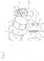
- an internal combustion engine 10 which is schematically outlined with a dotted line may be provided with a fuel system 12.
- the fuel system 12 may be any suitable system, but in the embodiment shown in Fig. 1 , the fuel system 12 is shown as a common rail fuel system.
- the fuel system 12 may have at least one rail 14 having a first generally longitudinal axis 15.
- the rail 14 may be connected to a second rail 14 (not shown) if preferred.
- the two rails 14 may be independent or they may be fluidly connected by for example a transfer conduit 16.
- the rail 14 may be fluidly connected with any number of injectors 18 via conduits 20.
- Each injector 18 may be provided with a suitable actuation arrangement (not shown) such as mechanical, fluid, or electronic actuation to actuate the injector 18 thereby selectively allowing fuel to pass through the injector 18 into a combustion chamber (not shown) associated with the respective injector 18.
- the rail 14 may act as a storage chamber for pressurized fuel.
- the fuel may be supplied by a pump 22 via a conduit 24.
- the fuel used is a heavy fuel such that at ambient temperatures the fuel displays a high viscosity
- the heating arrangement may for example heat the fuel to a temperature well in excess of 100° Celsius.
- the heating arrangement 26 may be of any suitable type and may be placed at any suitable position, for example it may be positioned upstream or downstream from the pump 22.
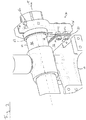
- the rail 14 may be mounted onto the engine 10 via a flexible mounting arrangement 30 shown in more detail in Figs. 2 and 3 .
- the mounting arrangement 30 may comprise a set of lamellae 32 having, at a neutral position, a second generally longitudinal axis 31.
- first and second generally longitudinal axes 15 and 31 may be substantially perpendicular to one each other.
- the set of lamellae 32 may have at least two lamellae 34 arranged adjacent to each other. In one embodiment as, shown in Figs. 2 and 3 , the set of lamellae 32 includes three lamellae 34, but any multiple number of lamellae 34 may be chosen if preferred.
- the lamellae may be formed as preferred, but in one embodiment at least one of the lamellae 34 may be formed from sheet metal in accordance with engineering standard St52-3. In one embodiment the thickness of at least one or of all lamellae is about 3 millimeter. In one embodiment the lamellae may have a generally rectangular shape. In other embodiments the lamellae may be generally shaped like, for example, squares, triangles, circles, ovals or any other suitable shape.
- the set of lamellae 32 may have a first portion 36 for connecting to a first element 38 which may be a first portion of the engine 10.
- the first element 38 may include base portions 40 of the lamellae 34 that are clamped together.
- the base portions 40 may be clamped together and fixed to the first element 38 via one or more fasteners 42 extending through holes 41 in the lamellae 34.
- the function of clamping the lamellae 34 and connecting the set of lamellae 32 to the first element 38 do not have to be combined and may be performed by different fastening arrangements.
- the base portions 40 of the lamellae 34 are clamped together such that no significant movement can take place of at least one base portion 40 relative to at least one other base portion 40.
- the set of lamellae 32 may further comprise a second portion 44 for connecting to a second element 46.
- the second portion 44 may include base portions 48 of the lamellae 34 that are clamped together and connected to the second element 46 via one or more fasteners 50 extending through holes 51 in the lamellae 34.
- the function of clamping the lamellae 34 and connecting the set of lamellae 32 to the first element 38 do not have to be combined and may be performed by different fastening arrangements.
- the base portions 48 of the lamellae 34 are clamped together such that no significant movement can take place of at least one base portion 48 relative to at least one other base portion 48.
- fasteners 42 and 50 are shown as threaded fasteners whereby each fastener 42 threads into a blind hole (not shown) in the first element 38 and each fastener 50 is of the nut-and-bolt type.
- the holes 41 and 51 in the lamellae 34 may be provided to correspond to the preferred fastening arrangement, but in one embodiment the holes in at least one or all of the lamellae are manufactured to DIN EN 20273. Manufacturing the holes 41 and 51 to this standard may contribute to reducing or preventing any significant movement of at least one base portion 40 relative to at least one other base portion 40, and/or of at least one base portion 48 relative to at least one other base portion 48.
- one or more spacers 52 may be provided between the set of lamellae 32 and the second element 46. In a similar vain, spacers (not shown) may be provided between the set of lamellae 32 and the first element 38.
- the second element 46 may be a bracket 54 for connecting with a third element 56 which may for example be the rail 14.
- the bracket 54 may be provided with a split 58 to enable the bracket 54 to be clamped around the rail 14 with a fastening arrangement 60 which may include for example threaded fasteners.
- an elastomeric member 62 may be incorporated in the flexible mounting arrangement 30.
- the elastomeric member 62 is interposed between the second and third elements 54 and 56, i.e. between the bracket 46 and the rail 14.
- the elastomeric member may also be positioned at any other suitable position such as between the set of lamellae 32 and the second element 46.
- the spacers 52 and the elastomeric member 62 may be co-located and/or even joined together to form a single component.
- the elastomeric member 62 may be made of any suitable material such as for example a rubber or rubber compound.
- a mounting arrangement such as flexible mounting arrangement 30 may provide a durable and flexible connection between two elements.
- the flexible mounting arrangement 30 may be used on the engine 10 to connect a rail 14 to another portion of the engine 10.
- the rail 14 may get hot as it may act as a conduit and/or temporary storage chamber for fuel which has been preheated to relatively high temperatures.
- the rail 14 may undergo significant thermally induced expansions and contractions. If the rail 14 was to be fixed such that no arrangements were made to compensate for the expansions and contractions, material failures may occur in the rail 14 and/or any elements connected thereto. Conversely, if the rail 14 was left wholly or partially loose, vibrations and movement of the rail 14 may also lead to material failures.
- the flexible mounting arrangement 30 is configured to adapt its shape to accommodate thennal expansion and contraction.
- the rail 14 may expand due to the heat transferred from the pre-heated fuel. In an element such as rail 14 this may manifest itself predominantly as an extension along the longitudinal axis 15.
- the set of lamellae 32 can due to its laminar construction bend generally between the first and second base portions 40 and 44.
- the lamellae 34 are configured to bend simultaneously whilst the base portions 40 of at least two or all lamellae 34 may remain in a substantially fixed position relative to each other.
- the base portions 48 of at least two or all lamellae 34 may remain in a substantially fixed position relative to each other.
- the set of lamellae 32 allows the first and second portions 36 and 44 to move relative to each other.
- the bracket 54 therefore can move with an associated portion of the rail 14 under the influence of the force 70 whilst remaining securely connected to the engine 10 via the first element 38.
- the elastomeric member 62 may be deformed to at least partially compensate for misalignment caused by the bending of the set of lamellae 32.
- the elastomeric element may compensate for misalignment between the bracket 54 and the rail 14.
- the spacers 52 may reduce or eliminate the transfer of any undesired mechanical stresses between the set of lamellae 32 and the first and/or second portions 36 and 40.
- the set of lamellae 32 may exert a counter force to the force 70 with a tendency to bias the set of lamellae 32 to a neutral position.
- This counterforce may contribute to the flexible mounting arrangement 30 providing a durable, strong and stable arrangement whilst allowing flexibility.
- the neutral position in this context may be interpreted as a position in which the set of lamellae 32 is subjected to a minimal amount of bending moment.
- the set of lamellae may be designed or fitted such that a certain amount of bending moment is present in the neutral position i.e. the set of lamellae may be pre-stressed.
- the flexible mounting arrangement may be configured to connect a component with an internal combustion engine via a set of lamellae having at least two adjacently arranged lamellae.
- the component may thermally expand during the internal combustion engine runs.
- the set of lamellae is configured to send to accomodate expansion of said component.
Landscapes
- Engineering & Computer Science (AREA)
- General Engineering & Computer Science (AREA)
- Mechanical Engineering (AREA)
- Chemical & Material Sciences (AREA)
- Combustion & Propulsion (AREA)
- Manufacturing & Machinery (AREA)
- Fuel-Injection Apparatus (AREA)
- Packaging Frangible Articles (AREA)
Claims (10)
- Flexible Befestigungsanordnung (30), umfassend:- eine Klammer (54) mit einer Festmachanordnung (60), wobei die Klammer (54) um ein Kraftstoffverteilerrohr (14) klemmt;- ein elastomerisches Bauteil (62), das sich zwischen der Klammer (54) und dem Kraftstoffverteilerrohr (14) befindet; und- einen Lamellensatz (32), der wenigstens zwei nebeneinander angeordnete Lamellen (34) aufweist, wobei der Lamellensatz (32) einen ersten Bereich (36), der angepasst ist, um sich mit einem Motorbereich einer Brennkraftmaschine (10) zu verbinden, und einen zweiten mit der Klammer (54) verbundenen Bereich (44) besitzt, wobei wenigstens einer der ersten und zweiten Bereiche (36, 44) Basisbereiche (40, 48) der wenigstens zwei Lamellen (34) aufweist, die zusammengeklemmt sind.
- Befestigungsanordnung (30) nach Anspruch 1, wobei die Basisbereiche (40, 48) der wenigstens zwei Lamellen (34) im Wesentlichen in einer fixen Stellung zueinander sind.
- Befestigungsanordnung (30) nach einem der vorhergehenden Ansprüche, wobei wenigstens ein Abstandsstück (52) zwischen dem Lamellensatz (32) und der Klammer (54) vorgesehen ist.
- Befestigungsanordnung (30) nach einem der vorhergehenden Ansprüche, wobei sich ein elastomerisches Bauteil (62) zwischen dem Lamellensatz (32) und der Klammer (54) befindet.
- Befestigungsanordnung (30) nach Anspruch 4, wobei der Lamellensatz (32) und das Kraftstoffverteilerrohr (14) in einer neutralen Position jeweils erste und zweite Längsachsen (15, 31) definieren, wobei die erste und zweite Längsachse (15, 31) im Wesentlichen senkrecht zueinander sind.
- Befestigungsanordnung (30) nach einem der vorhergehenden Ansprüche, wobei die wenigstens zwei Lamellen (34) dazu ausgebildet sind, sich gleichzeitig zu biegen.
- Befestigungsanordnung (30) nach einem der vorhergehenden Ansprüche, wobei der Lamellensatz (34) dazu ausgebildet ist, den ersten und zweiten Bereich (36, 44) in Richtung einer ersten Position relativ zueinander unter Vorspannung zu setzen.
- Befestigungsanordnung (30) nach einem der vorhergehenden Ansprüche, wobei die flexible Befestigungsanordnung (30) dazu ausgebildet ist, ihre Gestalt zum Aufnehmen von thermischer Expansion von wenigstens dem zweiten Element (46) anzupassen.
- Verfahren zum Verbinden einer flexiblen Befestigungsanordnung (30), wobei das Verfahren umfasst:Verbinden der Befestigungsanordnung (30) nach einem der vorhergehenden Ansprüche zwischen dem Kraftstoffverteilerrohr (14) und der Brennkraftmaschine (10);thermisches Expandieren des Kraftstoffverteilerrohrs (14), wenn die Brennkraftmaschine (10) betrieben wird;Biegen des Lamellensatzes (32) zum Aufnehmen der Ausdehnung der Komponente.
- Verfahren nach Anspruch 9, weiter umfassend:Deformieren eines elastomerischen Bauteils (62) zum wenigstens teilweisen Kompensieren einer durch das Biegen des Lamellensatzes verursachten Achsverschiebung.
Priority Applications (1)
| Application Number | Priority Date | Filing Date | Title |
|---|---|---|---|
| EP11151548.2A EP2305996B1 (de) | 2007-12-21 | 2007-12-21 | Flexible Montageanordnung |
Applications Claiming Priority (2)
| Application Number | Priority Date | Filing Date | Title |
|---|---|---|---|
| EP07150300A EP2072806B9 (de) | 2007-12-21 | 2007-12-21 | Flexible Montageanordnung |
| EP11151548.2A EP2305996B1 (de) | 2007-12-21 | 2007-12-21 | Flexible Montageanordnung |
Related Parent Applications (1)
| Application Number | Title | Priority Date | Filing Date |
|---|---|---|---|
| EP07150300A Division EP2072806B9 (de) | 2007-12-21 | 2007-12-21 | Flexible Montageanordnung |
Publications (2)
| Publication Number | Publication Date |
|---|---|
| EP2305996A1 EP2305996A1 (de) | 2011-04-06 |
| EP2305996B1 true EP2305996B1 (de) | 2018-01-24 |
Family
ID=39276296
Family Applications (2)
| Application Number | Title | Priority Date | Filing Date |
|---|---|---|---|
| EP07150300A Not-in-force EP2072806B9 (de) | 2007-12-21 | 2007-12-21 | Flexible Montageanordnung |
| EP11151548.2A Not-in-force EP2305996B1 (de) | 2007-12-21 | 2007-12-21 | Flexible Montageanordnung |
Family Applications Before (1)
| Application Number | Title | Priority Date | Filing Date |
|---|---|---|---|
| EP07150300A Not-in-force EP2072806B9 (de) | 2007-12-21 | 2007-12-21 | Flexible Montageanordnung |
Country Status (2)
| Country | Link |
|---|---|
| EP (2) | EP2072806B9 (de) |
| AT (1) | ATE537353T1 (de) |
Families Citing this family (3)
| Publication number | Priority date | Publication date | Assignee | Title |
|---|---|---|---|---|
| DE102010014498A1 (de) * | 2010-04-10 | 2011-10-13 | Audi Ag | Kraftstoffverteilrohr für ein Kraftfahrzeug und Verfahren zum Anordnen eines Kraftstoffverteilrohrs |
| DE102010051488A1 (de) * | 2010-11-15 | 2012-05-16 | Audi Ag | Befestigungsanordnung einer Kraftstoffzufuhrvorrichtung an einer Verbrennungskraftmaschine, sowie Verfahren zum Befestigen einer Kraftstoffzufuhrvorrichtung an einer Verbrennungskraftmaschine |
| DE102013219892A1 (de) * | 2013-10-01 | 2015-04-02 | Robert Bosch Gmbh | Halter zur Befestigung einer Komponente an einer Brennkraftmaschine |
Family Cites Families (4)
| Publication number | Priority date | Publication date | Assignee | Title |
|---|---|---|---|---|
| DE2827789A1 (de) * | 1978-06-24 | 1980-01-10 | Bosch Gmbh Robert | Kraftstoffeinspritzanlage |
| US4586477A (en) * | 1985-06-03 | 1986-05-06 | General Motors Corporation | Fuel rail assembly |
| GB2399392A (en) * | 2003-03-13 | 2004-09-15 | Visteon Global Tech Inc | I.c. engine moulded fuel rail with crash-resistant protecting structure |
| DE10313568B4 (de) * | 2003-03-26 | 2005-04-28 | Zeuna Staerker Kg | Kraftfahrzeug |
-
2007
- 2007-12-21 EP EP07150300A patent/EP2072806B9/de not_active Not-in-force
- 2007-12-21 AT AT07150300T patent/ATE537353T1/de active
- 2007-12-21 EP EP11151548.2A patent/EP2305996B1/de not_active Not-in-force
Also Published As
| Publication number | Publication date |
|---|---|
| ATE537353T1 (de) | 2011-12-15 |
| EP2305996A1 (de) | 2011-04-06 |
| EP2072806B1 (de) | 2011-12-14 |
| EP2072806A1 (de) | 2009-06-24 |
| EP2072806B9 (de) | 2012-09-05 |
Similar Documents
| Publication | Publication Date | Title |
|---|---|---|
| US7581530B2 (en) | Support element | |
| EP2176539B1 (de) | Brennstoff-einspritzanlage mit ausgleichselement | |
| US20090159049A1 (en) | Injector mounting structure | |
| EP3540314B1 (de) | Brennkammerwand für eine gasturbine | |
| EP2072806B9 (de) | Flexible Montageanordnung | |
| EP2875233B1 (de) | Kraftstoffleistenanordnung | |
| US7802558B2 (en) | Fuel delivery system | |
| US20140008908A1 (en) | Coupling with one-piece plural nipples | |
| CN102042141A (zh) | 用于内燃机的燃料系统的结构单元以及内燃机 | |
| CZ20023457A3 (en) | Fixing device | |
| JP5423865B2 (ja) | 燃料噴射装置およびクランプ部材 | |
| US7540273B2 (en) | Supporting element | |
| JP5136435B2 (ja) | 燃料噴射装置 | |
| EP3105439B1 (de) | Spaltsteuerungssystem mit halterungen | |
| CN1466656A (zh) | 用于燃料喷射阀上的补偿元件 | |
| US8251039B2 (en) | Heat shield | |
| EP3353409B1 (de) | Kraftstoffleistenanordnung und verfahren zur herstellung einer kraftstoffleistenanordnung | |
| CA2762462A1 (en) | Apparatus for injection molding | |
| US20050224053A1 (en) | Support element | |
| EP2587207B1 (de) | Energiesystem | |
| CN105518286B (zh) | 保持件以及具有燃料配给器和多个保持件的组件 | |
| US10160148B2 (en) | Manifold system nozzle retention | |
| CH711014A2 (de) | Dichtungsanordnung mit einer Wärmesperre für Turbomaschinen. | |
| US20150068198A1 (en) | Cooling def doser | |
| US9617903B2 (en) | Mechanical joint insert |
Legal Events
| Date | Code | Title | Description |
|---|---|---|---|
| PUAI | Public reference made under article 153(3) epc to a published international application that has entered the european phase |
Free format text: ORIGINAL CODE: 0009012 |
|
| AC | Divisional application: reference to earlier application |
Ref document number: 2072806 Country of ref document: EP Kind code of ref document: P |
|
| AK | Designated contracting states |
Kind code of ref document: A1 Designated state(s): AT BE BG CH CY CZ DE DK EE ES FI FR GB GR HU IE IS IT LI LT LU LV MC MT NL PL PT RO SE SI SK TR |
|
| AX | Request for extension of the european patent |
Extension state: AL BA HR MK RS |
|
| 17P | Request for examination filed |
Effective date: 20110329 |
|
| 17Q | First examination report despatched |
Effective date: 20110512 |
|
| RIN1 | Information on inventor provided before grant (corrected) |
Inventor name: ULRICH, HOPMANN Inventor name: ABRAHAM, VOLKER |
|
| GRAP | Despatch of communication of intention to grant a patent |
Free format text: ORIGINAL CODE: EPIDOSNIGR1 |
|
| RIC1 | Information provided on ipc code assigned before grant |
Ipc: F02M 61/16 20060101ALI20170629BHEP Ipc: F16B 5/02 20060101ALI20170629BHEP Ipc: F02M 55/02 20060101ALI20170629BHEP Ipc: F02M 61/14 20060101ALI20170629BHEP Ipc: F02M 63/00 20060101ALN20170629BHEP Ipc: F02M 69/46 20060101AFI20170629BHEP |
|
| INTG | Intention to grant announced |
Effective date: 20170724 |
|
| GRAS | Grant fee paid |
Free format text: ORIGINAL CODE: EPIDOSNIGR3 |
|
| GRAA | (expected) grant |
Free format text: ORIGINAL CODE: 0009210 |
|
| AC | Divisional application: reference to earlier application |
Ref document number: 2072806 Country of ref document: EP Kind code of ref document: P |
|
| AK | Designated contracting states |
Kind code of ref document: B1 Designated state(s): AT BE BG CH CY CZ DE DK EE ES FI FR GB GR HU IE IS IT LI LT LU LV MC MT NL PL PT RO SE SI SK TR |
|
| REG | Reference to a national code |
Ref country code: GB Ref legal event code: FG4D |
|
| REG | Reference to a national code |
Ref country code: CH Ref legal event code: EP |
|
| REG | Reference to a national code |
Ref country code: AT Ref legal event code: REF Ref document number: 965929 Country of ref document: AT Kind code of ref document: T Effective date: 20180215 |
|
| REG | Reference to a national code |
Ref country code: IE Ref legal event code: FG4D |
|
| REG | Reference to a national code |
Ref country code: DE Ref legal event code: R096 Ref document number: 602007053839 Country of ref document: DE |
|
| REG | Reference to a national code |
Ref country code: NL Ref legal event code: MP Effective date: 20180124 |
|
| REG | Reference to a national code |
Ref country code: LT Ref legal event code: MG4D |
|
| REG | Reference to a national code |
Ref country code: AT Ref legal event code: MK05 Ref document number: 965929 Country of ref document: AT Kind code of ref document: T Effective date: 20180124 |
|
| PG25 | Lapsed in a contracting state [announced via postgrant information from national office to epo] |
Ref country code: NL Free format text: LAPSE BECAUSE OF FAILURE TO SUBMIT A TRANSLATION OF THE DESCRIPTION OR TO PAY THE FEE WITHIN THE PRESCRIBED TIME-LIMIT Effective date: 20180124 |
|
| PG25 | Lapsed in a contracting state [announced via postgrant information from national office to epo] |
Ref country code: FI Free format text: LAPSE BECAUSE OF FAILURE TO SUBMIT A TRANSLATION OF THE DESCRIPTION OR TO PAY THE FEE WITHIN THE PRESCRIBED TIME-LIMIT Effective date: 20180124 Ref country code: CY Free format text: LAPSE BECAUSE OF FAILURE TO SUBMIT A TRANSLATION OF THE DESCRIPTION OR TO PAY THE FEE WITHIN THE PRESCRIBED TIME-LIMIT Effective date: 20180124 Ref country code: ES Free format text: LAPSE BECAUSE OF FAILURE TO SUBMIT A TRANSLATION OF THE DESCRIPTION OR TO PAY THE FEE WITHIN THE PRESCRIBED TIME-LIMIT Effective date: 20180124 Ref country code: LT Free format text: LAPSE BECAUSE OF FAILURE TO SUBMIT A TRANSLATION OF THE DESCRIPTION OR TO PAY THE FEE WITHIN THE PRESCRIBED TIME-LIMIT Effective date: 20180124 |
|
| PG25 | Lapsed in a contracting state [announced via postgrant information from national office to epo] |
Ref country code: AT Free format text: LAPSE BECAUSE OF FAILURE TO SUBMIT A TRANSLATION OF THE DESCRIPTION OR TO PAY THE FEE WITHIN THE PRESCRIBED TIME-LIMIT Effective date: 20180124 Ref country code: IS Free format text: LAPSE BECAUSE OF FAILURE TO SUBMIT A TRANSLATION OF THE DESCRIPTION OR TO PAY THE FEE WITHIN THE PRESCRIBED TIME-LIMIT Effective date: 20180524 Ref country code: SE Free format text: LAPSE BECAUSE OF FAILURE TO SUBMIT A TRANSLATION OF THE DESCRIPTION OR TO PAY THE FEE WITHIN THE PRESCRIBED TIME-LIMIT Effective date: 20180124 Ref country code: LV Free format text: LAPSE BECAUSE OF FAILURE TO SUBMIT A TRANSLATION OF THE DESCRIPTION OR TO PAY THE FEE WITHIN THE PRESCRIBED TIME-LIMIT Effective date: 20180124 Ref country code: BG Free format text: LAPSE BECAUSE OF FAILURE TO SUBMIT A TRANSLATION OF THE DESCRIPTION OR TO PAY THE FEE WITHIN THE PRESCRIBED TIME-LIMIT Effective date: 20180424 Ref country code: GR Free format text: LAPSE BECAUSE OF FAILURE TO SUBMIT A TRANSLATION OF THE DESCRIPTION OR TO PAY THE FEE WITHIN THE PRESCRIBED TIME-LIMIT Effective date: 20180425 Ref country code: PL Free format text: LAPSE BECAUSE OF FAILURE TO SUBMIT A TRANSLATION OF THE DESCRIPTION OR TO PAY THE FEE WITHIN THE PRESCRIBED TIME-LIMIT Effective date: 20180124 |
|
| REG | Reference to a national code |
Ref country code: DE Ref legal event code: R097 Ref document number: 602007053839 Country of ref document: DE |
|
| PG25 | Lapsed in a contracting state [announced via postgrant information from national office to epo] |
Ref country code: RO Free format text: LAPSE BECAUSE OF FAILURE TO SUBMIT A TRANSLATION OF THE DESCRIPTION OR TO PAY THE FEE WITHIN THE PRESCRIBED TIME-LIMIT Effective date: 20180124 Ref country code: IT Free format text: LAPSE BECAUSE OF FAILURE TO SUBMIT A TRANSLATION OF THE DESCRIPTION OR TO PAY THE FEE WITHIN THE PRESCRIBED TIME-LIMIT Effective date: 20180124 Ref country code: EE Free format text: LAPSE BECAUSE OF FAILURE TO SUBMIT A TRANSLATION OF THE DESCRIPTION OR TO PAY THE FEE WITHIN THE PRESCRIBED TIME-LIMIT Effective date: 20180124 |
|
| PG25 | Lapsed in a contracting state [announced via postgrant information from national office to epo] |
Ref country code: SK Free format text: LAPSE BECAUSE OF FAILURE TO SUBMIT A TRANSLATION OF THE DESCRIPTION OR TO PAY THE FEE WITHIN THE PRESCRIBED TIME-LIMIT Effective date: 20180124 Ref country code: CZ Free format text: LAPSE BECAUSE OF FAILURE TO SUBMIT A TRANSLATION OF THE DESCRIPTION OR TO PAY THE FEE WITHIN THE PRESCRIBED TIME-LIMIT Effective date: 20180124 Ref country code: DK Free format text: LAPSE BECAUSE OF FAILURE TO SUBMIT A TRANSLATION OF THE DESCRIPTION OR TO PAY THE FEE WITHIN THE PRESCRIBED TIME-LIMIT Effective date: 20180124 |
|
| PLBE | No opposition filed within time limit |
Free format text: ORIGINAL CODE: 0009261 |
|
| STAA | Information on the status of an ep patent application or granted ep patent |
Free format text: STATUS: NO OPPOSITION FILED WITHIN TIME LIMIT |
|
| 26N | No opposition filed |
Effective date: 20181025 |
|
| PG25 | Lapsed in a contracting state [announced via postgrant information from national office to epo] |
Ref country code: SI Free format text: LAPSE BECAUSE OF FAILURE TO SUBMIT A TRANSLATION OF THE DESCRIPTION OR TO PAY THE FEE WITHIN THE PRESCRIBED TIME-LIMIT Effective date: 20180124 |
|
| REG | Reference to a national code |
Ref country code: DE Ref legal event code: R119 Ref document number: 602007053839 Country of ref document: DE |
|
| REG | Reference to a national code |
Ref country code: CH Ref legal event code: PL |
|
| GBPC | Gb: european patent ceased through non-payment of renewal fee |
Effective date: 20181221 |
|
| PG25 | Lapsed in a contracting state [announced via postgrant information from national office to epo] |
Ref country code: LU Free format text: LAPSE BECAUSE OF NON-PAYMENT OF DUE FEES Effective date: 20181221 Ref country code: MC Free format text: LAPSE BECAUSE OF FAILURE TO SUBMIT A TRANSLATION OF THE DESCRIPTION OR TO PAY THE FEE WITHIN THE PRESCRIBED TIME-LIMIT Effective date: 20180124 |
|
| REG | Reference to a national code |
Ref country code: IE Ref legal event code: MM4A |
|
| REG | Reference to a national code |
Ref country code: BE Ref legal event code: MM Effective date: 20181231 |
|
| PG25 | Lapsed in a contracting state [announced via postgrant information from national office to epo] |
Ref country code: DE Free format text: LAPSE BECAUSE OF NON-PAYMENT OF DUE FEES Effective date: 20190702 Ref country code: IE Free format text: LAPSE BECAUSE OF NON-PAYMENT OF DUE FEES Effective date: 20181221 Ref country code: FR Free format text: LAPSE BECAUSE OF NON-PAYMENT OF DUE FEES Effective date: 20181231 |
|
| PG25 | Lapsed in a contracting state [announced via postgrant information from national office to epo] |
Ref country code: BE Free format text: LAPSE BECAUSE OF NON-PAYMENT OF DUE FEES Effective date: 20181231 |
|
| PG25 | Lapsed in a contracting state [announced via postgrant information from national office to epo] |
Ref country code: CH Free format text: LAPSE BECAUSE OF NON-PAYMENT OF DUE FEES Effective date: 20181231 Ref country code: GB Free format text: LAPSE BECAUSE OF NON-PAYMENT OF DUE FEES Effective date: 20181221 Ref country code: LI Free format text: LAPSE BECAUSE OF NON-PAYMENT OF DUE FEES Effective date: 20181231 |
|
| PG25 | Lapsed in a contracting state [announced via postgrant information from national office to epo] |
Ref country code: MT Free format text: LAPSE BECAUSE OF NON-PAYMENT OF DUE FEES Effective date: 20181221 |
|
| PG25 | Lapsed in a contracting state [announced via postgrant information from national office to epo] |
Ref country code: TR Free format text: LAPSE BECAUSE OF FAILURE TO SUBMIT A TRANSLATION OF THE DESCRIPTION OR TO PAY THE FEE WITHIN THE PRESCRIBED TIME-LIMIT Effective date: 20180124 |
|
| PG25 | Lapsed in a contracting state [announced via postgrant information from national office to epo] |
Ref country code: PT Free format text: LAPSE BECAUSE OF FAILURE TO SUBMIT A TRANSLATION OF THE DESCRIPTION OR TO PAY THE FEE WITHIN THE PRESCRIBED TIME-LIMIT Effective date: 20180124 |
|
| PG25 | Lapsed in a contracting state [announced via postgrant information from national office to epo] |
Ref country code: HU Free format text: LAPSE BECAUSE OF FAILURE TO SUBMIT A TRANSLATION OF THE DESCRIPTION OR TO PAY THE FEE WITHIN THE PRESCRIBED TIME-LIMIT; INVALID AB INITIO Effective date: 20071221 |