EP2305999A2 - Systeme und Methoden, eine Rotor-Blatt-Ausdehnung für Gebrauch in einer Windturbine zu versammeln - Google Patents
Systeme und Methoden, eine Rotor-Blatt-Ausdehnung für Gebrauch in einer Windturbine zu versammeln Download PDFInfo
- Publication number
- EP2305999A2 EP2305999A2 EP10178732A EP10178732A EP2305999A2 EP 2305999 A2 EP2305999 A2 EP 2305999A2 EP 10178732 A EP10178732 A EP 10178732A EP 10178732 A EP10178732 A EP 10178732A EP 2305999 A2 EP2305999 A2 EP 2305999A2
- Authority
- EP
- European Patent Office
- Prior art keywords
- blade
- coupled
- tip portion
- base member
- extension assembly
- Prior art date
- Legal status (The legal status is an assumption and is not a legal conclusion. Google has not performed a legal analysis and makes no representation as to the accuracy of the status listed.)
- Granted
Links
- 238000000034 method Methods 0.000 title description 26
- 238000007789 sealing Methods 0.000 claims description 4
- 230000008878 coupling Effects 0.000 description 10
- 238000010168 coupling process Methods 0.000 description 10
- 238000005859 coupling reaction Methods 0.000 description 10
- 230000006870 function Effects 0.000 description 7
- 238000004519 manufacturing process Methods 0.000 description 5
- 230000013011 mating Effects 0.000 description 4
- 230000000712 assembly Effects 0.000 description 3
- 238000000429 assembly Methods 0.000 description 3
- 230000009467 reduction Effects 0.000 description 3
- 229910000831 Steel Inorganic materials 0.000 description 2
- 230000005534 acoustic noise Effects 0.000 description 2
- 238000000926 separation method Methods 0.000 description 2
- 239000010959 steel Substances 0.000 description 2
- XAGFODPZIPBFFR-UHFFFAOYSA-N aluminium Chemical compound [Al] XAGFODPZIPBFFR-UHFFFAOYSA-N 0.000 description 1
- 229910052782 aluminium Inorganic materials 0.000 description 1
- 230000001427 coherent effect Effects 0.000 description 1
- 230000005611 electricity Effects 0.000 description 1
- 239000011152 fibreglass Substances 0.000 description 1
- -1 for example Substances 0.000 description 1
- 230000006872 improvement Effects 0.000 description 1
- 230000003993 interaction Effects 0.000 description 1
- 239000000463 material Substances 0.000 description 1
- 230000007246 mechanism Effects 0.000 description 1
- 230000007935 neutral effect Effects 0.000 description 1
- 239000012811 non-conductive material Substances 0.000 description 1
- 238000010248 power generation Methods 0.000 description 1
- 230000002028 premature Effects 0.000 description 1
- 230000005855 radiation Effects 0.000 description 1
- 238000009420 retrofitting Methods 0.000 description 1
- 239000013598 vector Substances 0.000 description 1
Images




Classifications
-
- F—MECHANICAL ENGINEERING; LIGHTING; HEATING; WEAPONS; BLASTING
- F03—MACHINES OR ENGINES FOR LIQUIDS; WIND, SPRING, OR WEIGHT MOTORS; PRODUCING MECHANICAL POWER OR A REACTIVE PROPULSIVE THRUST, NOT OTHERWISE PROVIDED FOR
- F03D—WIND MOTORS
- F03D1/00—Wind motors with rotation axis substantially parallel to the air flow entering the rotor
- F03D1/06—Rotors
- F03D1/065—Rotors characterised by their construction elements
- F03D1/0675—Rotors characterised by their construction elements of the blades
-
- F—MECHANICAL ENGINEERING; LIGHTING; HEATING; WEAPONS; BLASTING
- F05—INDEXING SCHEMES RELATING TO ENGINES OR PUMPS IN VARIOUS SUBCLASSES OF CLASSES F01-F04
- F05B—INDEXING SCHEME RELATING TO WIND, SPRING, WEIGHT, INERTIA OR LIKE MOTORS, TO MACHINES OR ENGINES FOR LIQUIDS COVERED BY SUBCLASSES F03B, F03D AND F03G
- F05B2230/00—Manufacture
- F05B2230/80—Repairing, retrofitting or upgrading methods
-
- F—MECHANICAL ENGINEERING; LIGHTING; HEATING; WEAPONS; BLASTING
- F05—INDEXING SCHEMES RELATING TO ENGINES OR PUMPS IN VARIOUS SUBCLASSES OF CLASSES F01-F04
- F05B—INDEXING SCHEME RELATING TO WIND, SPRING, WEIGHT, INERTIA OR LIKE MOTORS, TO MACHINES OR ENGINES FOR LIQUIDS COVERED BY SUBCLASSES F03B, F03D AND F03G
- F05B2240/00—Components
- F05B2240/20—Rotors
- F05B2240/30—Characteristics of rotor blades, i.e. of any element transforming dynamic fluid energy to or from rotational energy and being attached to a rotor
- F05B2240/302—Segmented or sectional blades
-
- F—MECHANICAL ENGINEERING; LIGHTING; HEATING; WEAPONS; BLASTING
- F05—INDEXING SCHEMES RELATING TO ENGINES OR PUMPS IN VARIOUS SUBCLASSES OF CLASSES F01-F04
- F05B—INDEXING SCHEME RELATING TO WIND, SPRING, WEIGHT, INERTIA OR LIKE MOTORS, TO MACHINES OR ENGINES FOR LIQUIDS COVERED BY SUBCLASSES F03B, F03D AND F03G
- F05B2240/00—Components
- F05B2240/20—Rotors
- F05B2240/30—Characteristics of rotor blades, i.e. of any element transforming dynamic fluid energy to or from rotational energy and being attached to a rotor
- F05B2240/307—Blade tip, e.g. winglets
-
- F—MECHANICAL ENGINEERING; LIGHTING; HEATING; WEAPONS; BLASTING
- F05—INDEXING SCHEMES RELATING TO ENGINES OR PUMPS IN VARIOUS SUBCLASSES OF CLASSES F01-F04
- F05B—INDEXING SCHEME RELATING TO WIND, SPRING, WEIGHT, INERTIA OR LIKE MOTORS, TO MACHINES OR ENGINES FOR LIQUIDS COVERED BY SUBCLASSES F03B, F03D AND F03G
- F05B2260/00—Function
- F05B2260/96—Preventing, counteracting or reducing vibration or noise
-
- Y—GENERAL TAGGING OF NEW TECHNOLOGICAL DEVELOPMENTS; GENERAL TAGGING OF CROSS-SECTIONAL TECHNOLOGIES SPANNING OVER SEVERAL SECTIONS OF THE IPC; TECHNICAL SUBJECTS COVERED BY FORMER USPC CROSS-REFERENCE ART COLLECTIONS [XRACs] AND DIGESTS
- Y02—TECHNOLOGIES OR APPLICATIONS FOR MITIGATION OR ADAPTATION AGAINST CLIMATE CHANGE
- Y02E—REDUCTION OF GREENHOUSE GAS [GHG] EMISSIONS, RELATED TO ENERGY GENERATION, TRANSMISSION OR DISTRIBUTION
- Y02E10/00—Energy generation through renewable energy sources
- Y02E10/70—Wind energy
- Y02E10/72—Wind turbines with rotation axis in wind direction
-
- Y—GENERAL TAGGING OF NEW TECHNOLOGICAL DEVELOPMENTS; GENERAL TAGGING OF CROSS-SECTIONAL TECHNOLOGIES SPANNING OVER SEVERAL SECTIONS OF THE IPC; TECHNICAL SUBJECTS COVERED BY FORMER USPC CROSS-REFERENCE ART COLLECTIONS [XRACs] AND DIGESTS
- Y02—TECHNOLOGIES OR APPLICATIONS FOR MITIGATION OR ADAPTATION AGAINST CLIMATE CHANGE
- Y02P—CLIMATE CHANGE MITIGATION TECHNOLOGIES IN THE PRODUCTION OR PROCESSING OF GOODS
- Y02P70/00—Climate change mitigation technologies in the production process for final industrial or consumer products
- Y02P70/50—Manufacturing or production processes characterised by the final manufactured product
-
- Y—GENERAL TAGGING OF NEW TECHNOLOGICAL DEVELOPMENTS; GENERAL TAGGING OF CROSS-SECTIONAL TECHNOLOGIES SPANNING OVER SEVERAL SECTIONS OF THE IPC; TECHNICAL SUBJECTS COVERED BY FORMER USPC CROSS-REFERENCE ART COLLECTIONS [XRACs] AND DIGESTS
- Y10—TECHNICAL SUBJECTS COVERED BY FORMER USPC
- Y10T—TECHNICAL SUBJECTS COVERED BY FORMER US CLASSIFICATION
- Y10T29/00—Metal working
- Y10T29/49—Method of mechanical manufacture
- Y10T29/49316—Impeller making
- Y10T29/49318—Repairing or disassembling
-
- Y—GENERAL TAGGING OF NEW TECHNOLOGICAL DEVELOPMENTS; GENERAL TAGGING OF CROSS-SECTIONAL TECHNOLOGIES SPANNING OVER SEVERAL SECTIONS OF THE IPC; TECHNICAL SUBJECTS COVERED BY FORMER USPC CROSS-REFERENCE ART COLLECTIONS [XRACs] AND DIGESTS
- Y10—TECHNICAL SUBJECTS COVERED BY FORMER USPC
- Y10T—TECHNICAL SUBJECTS COVERED BY FORMER US CLASSIFICATION
- Y10T29/00—Metal working
- Y10T29/49—Method of mechanical manufacture
- Y10T29/49316—Impeller making
- Y10T29/49336—Blade making
-
- Y—GENERAL TAGGING OF NEW TECHNOLOGICAL DEVELOPMENTS; GENERAL TAGGING OF CROSS-SECTIONAL TECHNOLOGIES SPANNING OVER SEVERAL SECTIONS OF THE IPC; TECHNICAL SUBJECTS COVERED BY FORMER USPC CROSS-REFERENCE ART COLLECTIONS [XRACs] AND DIGESTS
- Y10—TECHNICAL SUBJECTS COVERED BY FORMER USPC
- Y10T—TECHNICAL SUBJECTS COVERED BY FORMER US CLASSIFICATION
- Y10T29/00—Metal working
- Y10T29/49—Method of mechanical manufacture
- Y10T29/49316—Impeller making
- Y10T29/49336—Blade making
- Y10T29/49337—Composite blade
Definitions
- the embodiments described herein relate generally to methods and systems for assembling a wind turbine including a blade extension, and more particularly, to systems and methods for assembling a blade extension assembly for use in a wind turbine.
- At least some known wind turbine towers include a nacelle fixed atop a tower, wherein the nacelle includes a rotor coupled to a generator through a shaft.
- a plurality of blades extend from the rotor. The blades are oriented such that wind passing over the blades turns the rotor and rotates the shaft, thereby driving the generator to generate electricity.
- Blades with a high aerodynamic loading generate increased lift, and the increased lift tends to increase the efficiency of the blade.
- blades with increased loading also tend to have a greater surface area at the blade tip, which may contribute to stronger vortices being generated at the blade tip.
- the increased strength of the vortices and the interaction of each vortex with the blade surface can increase the noise generated by the turbine.
- turbulent kinetic energy (TKE) at the blade tip increases pressure fluctuations that are responsible for noise generation.
- TKE turbulent kinetic energy
- a method of assembling a blade extension assembly for use with a wind turbine includes removing a tip end of a tip portion of a rotor blade and coupling a tip wall to the tip portion.
- the tip wall extends between a first sidewall and a second sidewall and includes a plurality of slots defined therein.
- a blade extension assembly is coupled to the tip portion.
- a blade extension assembly for use in a wind turbine.
- the blade extension includes a tip wall adapted to be coupled to a tip portion of a rotor blade and a base member adapted to be coupled to the tip portion.
- the tip portion includes a blade outer surface.
- a plurality of support rods are coupled to and extend from the base member towards the tip portion.
- the support rods are coupled to the tip portion with a plurality of shear pins at least partially inserted therein.
- a wind turbine in yet another aspect, includes a tower, a nacelle coupled to the tower, a hub rotatably coupled to the nacelle, and at least one rotor blade coupled to the hub.
- the rotor blade includes a tip portion and a blade outer surface.
- a blade extension assembly is coupled to the rotor blade.
- the blade extension assembly includes a tip wall coupled to the tip portion, a base member coupled to the tip portion, and a plurality of support bars coupled to and extending from the base member towards the tip portion. The support bars are coupled to the tip portion.
- a rotor blade for use with a wind turbine.
- the rotor blade includes a tip portion; and a blade extension assembly coupled to the tip portion.
- the blade extension assembly includes a tip wall coupled to the tip portion, a base member coupled to the tip portion, and a plurality of support bars coupled to and extending from the base member towards the tip portion. The support bars are coupled to the tip portion.
- Various embodiments described herein facilitate reducing noise generated at the tip portion of a rotor blade by the rotation of the rotor blade, and facilitate increasing the electrical power produced by a wind turbine. More specifically, the blade extension assembly described herein enables an increase in a length and blade surface area of an existing rotor blade, thereby facilitating an increase in the energy generated in a wind turbine. In addition, the blade extension assembly described herein facilitates modifying the vortices that trail from the rotor blade, thereby facilitating reduced levels of vortex turbulent kinetic energy (TKE), and facilitating reduced pressure fluctuations across the rotor blade surface that generate noise.
- TKE vortex turbulent kinetic energy
- the embodiments described herein include a wind turbine system that enables an increase in wind turbine power production and a reduction in the generation of acoustic noise during operation of the wind turbine.
- the systems and methods described herein facilitate retrofitting an existing rotor blade to increase a length and surface area of the rotor blade. More specifically, the blade extension assembly described herein enables an existing rotor blade to be modified to facilitate reducing noise generated at the tip portion of a rotor blade by the rotation of the rotor blade, and facilitate increasing the electrical power produced by a wind turbine.
- FIG. 1 is a perspective view of an exemplary wind turbine 10.
- Figure 2 is an enlarged perspective view of an exemplary wind turbine 10. Components shown in Figure 1 are labeled with similar reference numbers in Figure 2 .
- wind turbine 10 is a horizontal-axis wind turbine.
- wind turbine 10 may be a vertical-axis wind turbine.
- wind turbine 10 includes a tower 12 that extends from a supporting surface 14, a nacelle 16 mounted on tower 12, and a rotor 18 that is coupled to nacelle 16.
- Rotor 18 includes a rotatable hub 20 and at least one rotor blade 22 coupled to and extending outward from hub 20.
- rotor 18 has three rotor blades 22.
- rotor 18 includes more or less than three rotor blades 22.
- tower 12 is fabricated from tubular steel such that a cavity (not shown in Figure 1 ) is defined between supporting surface 14 and nacelle 16.
- tower 12 is any suitable type of tower. A height of tower 12 is selected based upon factors and conditions known in the art.
- Rotor blades 22 are spaced about hub 20 to facilitate rotating rotor 18.
- Rotor blades 22 include a blade root 24 and a blade tip 26, and are mated to hub 20 by coupling blade root 24 to hub 20 at a plurality of load transfer regions 27.
- Load transfer regions 27 have a hub load transfer region and a blade load transfer region (both not shown in Figure 1 ). Loads induced to rotor blades 22 are transferred to hub 20 by load transfer regions 27.
- rotor blades 22 have a length L 1 that extends from blade root 24 to blade tip 26. Length L 1 has a range from about 15 meters (m) to about 91 m. Alternatively, rotor blades 22 may have any suitable length that enables wind turbine 10 to function as described herein. For example, other non-limiting examples of blade lengths include 10 m or less, 20 m, and 37 m, or a length that is greater than 91 m. As wind strikes rotor blades 22 from a direction 28, rotor 18 is rotated about an axis of rotation 30. As rotor blades 22 are rotated and subjected to centrifugal forces, rotor blades 22 are also subjected to various forces and moments.
- rotor blades 22 may deflect and/or rotate from a neutral, or non-deflected, position to a deflected position.
- a pitch adjustment system 32 rotates rotor blades 22 about a pitch axis 34 for adjusting an orientation of rotor blades 22 with respect to direction 28 of the wind.
- a speed of rotation of rotor 18 may be controlled by adjusting the orientation of at least one rotor blade 22 relative to wind vectors.
- a pitch of each rotor blade 22 is controlled individually by a control system 36.
- the blade pitch for all rotor blades 22 may be controlled simultaneously by control system 36.
- a yaw direction of nacelle 16 may be controlled about a yaw axis 38 to position rotor blades 22 with respect to direction 28.
- Wind turbine 10 also includes a blade extension assembly 40 coupled to each rotor blade 22.
- wind turbine 10 includes three blade extension assemblies 40 that each correspond with a respective rotor blade 22.
- wind turbine 10 includes any number of blade extension assemblies 40 that correspond to the number of rotor blades 22 that enable wind turbine 10 to function as described herein.
- Blade extension assembly 40 is coupled to blade tip 26 and extends axially and/or radially outward from rotor blade 22.
- Each rotor blade 22 includes a blade extension assembly 40.
- at least one rotor blade 22 includes a blade extension assembly 40.
- each blade extension assembly 40 is substantially similar, however, at least one blade extension assembly 40 may be different than at least one other blade extension assembly 40.
- blade extension assembly 40 is positioned proximate blade tip 26, such that rotor blade 22 and blade extension assembly 40 define a length L 2 that is greater than length L 1 of rotor blade 22.
- FIG 3 is a perspective view of exemplary blade extension assembly 100 suitable for use with wind turbine 10.
- rotor blades 22 are identical and each includes a first sidewall 102 and a cooperating second sidewall 104.
- Second sidewall 104 is coupled to first sidewall 102 along a leading edge 106 and along an axially-spaced trailing edge 108.
- First sidewall 102 and second sidewall 104 are coupled together to define a cavity 110 between first sidewall 102 and second sidewall 104.
- cavity 110 is bordered at least in part by a first sidewall inner surface 112 and a second sidewall inner surface 114.
- a tip wall 116 is positioned at a tip end 118 of a blade tip portion 120.
- Tip wall 116 is coupled to first sidewall 102 and second sidewall 104 and extends between leading edge 106 and trailing edge 108.
- tip wall 116 includes surface 117 that is substantially perpendicular to first sidewall 102 and second sidewall 104.
- tip wall 116 includes at least one of a concave and/or convex surface 117.
- tip wall 116 includes a convex surface 117.
- At least one spar 121 is positioned within cavity 110 and extends from a blade root portion 126 towards blade tip portion 120.
- rotor blade 22 includes a forward, or first spar 122 and an aft, or second spar 124.
- rotor blade 22 includes any number of spars such that rotor blade 22 functions as described herein.
- First spar 122 is positioned within cavity 110 and extends from blade root portion 126 towards blade tip portion 120.
- First spar 122 is positioned between a centerline 128 and leading edge 106, such that a forward cavity 130 is defined between leading edge 106 and first spar 122.
- Second spar 124 is positioned within cavity 110 and extends from blade root portion 126 towards blade tip portion 120.
- Second spar 124 is positioned substantially parallel to first spar 122 and between centerline 128 and trailing edge 108.
- a center cavity 132 is defined between first spar 122 and second spar 124, and an aft cavity 134 is defined between second spar 124 and trailing edge 108.
- First spar 122 and second spar 124 extend between first sidewall 102 and second sidewall 104, are coupled to first sidewall 102 and second sidewall 104, and are configured to facilitate a reduction in a flexion and a deformation of rotor blade 22.
- rotor blade 22 includes only one spar 121 positioned within cavity 110.
- rotor blade 22 includes any number of spars 121 that enable rotor blade 22 to function as described herein.
- blade extension assembly 100 is coupled to blade tip portion 120.
- Blade extension assembly 100 includes a base member 136 and plurality of support rods 138.
- Support rods 138 extend outward from blade extension assembly 100 and are inserted into blade tip portion 120.
- support rods 138 are formed unitarily with base member 136.
- Tip wall 116 includes a plurality of openings 140 sized and shaped to receive a corresponding support rod 138.
- tip wall 116 includes two openings 140, however, it should be understood that tip wall 116 may include any number of openings 140 that correspond to the number of support rods 138.
- blade extension assembly 100 includes a first, or forward support rod 142 and a second, or aft support rod 144.
- Forward support rod 142 is coupled to base member 136 and extends outward from base member 136 towards leading edge 106.
- Forward support rod 142 extends through a tip wall opening 146 and is positioned within forward cavity 130.
- Aft support rod 144 is coupled to base member 136 and extends outward from base member 136 through a tip wall opening 148 and is positioned within aft cavity 134.
- Forward support rod 142 includes a base end 150 and a tip end 152.
- Tip end 152 includes a forward support tip opening 154.
- First sidewall 102 includes a corresponding forward opening 156.
- Forward support rod 142 is positioned in forward cavity 130 such that forward opening 156 is concentrically aligned with forward support tip opening 154.
- Aft support rod 144 includes a base end 158 and a tip end 160.
- Tip end 160 includes an aft support tip opening 162.
- First sidewall 102 includes a corresponding aft opening 164.
- Aft support rod 144 is positioned within aft cavity 134 such that aft support tip opening 162 is concentrically aligned with aft opening 164.
- a plurality of fasteners, or shear pins 166 are inserted through forward opening 156, forward support tip opening 154, aft opening 164, and aft support tip opening 162, such that rotor blade 22 is fixedly coupled to blade extension assembly 100.
- shear pins 166 extend at least partially through support rods 138.
- shear pins 166 extend entirely through support rods 138 such that shear pins 166 extend between first sidewall 102 and second sidewall 104.
- second sidewall 104 includes corresponding forward and aft openings 156 and 164, such that shear pins 166 extend from second sidewall 104 through support rods 138.
- forward support rod 142 and/or aft support rod 144 are coupled to at least one spar 121.
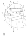
- FIG 4 is a perspective view of an exemplary rotor blade 22 suitable for use with wind turbine 10. Components shown in Figure 4 that are also shown in Figure 3 are labeled with similar reference numbers in Figure 4 .
- rotor blade 22 includes a lightning receptor 168 positioned within blade tip portion 120.
- Tip wall 116 includes a plurality of slots 170 sized and shaped to receive support rods 138 therein.
- tip wall 116 includes a forward slot 171 and an aft slot 172.
- Forward slot 171 is sized and shaped to receive forward support rod 142.
- Aft slot 172 is sized and shaped to receive aft support rod 144 therein.
- Forward support rod 142 extends inward through forward cavity 130 and is aligned obliquely from rotor blade centerline 128 towards leading edge 106.
- Forward opening 156 is positioned between forward spar 122 and leading edge 106, such that a forward shear pin 174 is inserted through forward opening 156 and extends into forward cavity 130.
- Aft opening 164 is defined through first sidewall 102 and is positioned between aft spar 124 and trailing edge 108, such that an aft shear pin 176 is inserted through aft opening 164 and extends into aft cavity 134.
- Aft support rod 144 extends inward through cavity 110 and is aligned obliquely from rotor blade centerline 128 towards trailing edge 108, such that aft support rod 144 extends through to aft cavity 134.
- Forward shear pin 174 is inserted through forward opening 156 and extends at least partially through forward support rod 142.
- Aft shear pin 176 is inserted through aft opening 164 and extends at least partially through aft support rod 144.
- shear pins 174 and 176 are cylindrically-shaped. In an alternative embodiment, shear pins 174 and 176 are substantially rectangular-shaped.
- shear pins 174 and 176 are fabricated from a non-conductive material, such as, for example, fiberglass, however, shear pins 174 and 176 may be fabricated from aluminum, steel, or any suitable material that enables blade extension assembly 100 to function as described herein.
- FIG. 5 is a cross-sectional view of an alternative blade extension assembly 200 suitable for use with rotor blade 22. Components shown in Figure 3 are labeled with similar reference numbers in Figure 5 .
- rotor blade 22 includes a pressure side surface 202 and an opposing suction side surface 204.
- Tip wall 116 extends between pressure side surface 202 and suction side surface 204.
- Blade extension assembly 200 includes a base member 206 that includes a pressure side interior surface 208, a suction side interior surface 210, and an inner wall 218.
- Base member 206 further includes a first outer surface 214 and a second outer surface 216. Pressure side interior surface 208 and suction side interior surface 210 extend outward from inner wall 218 such that interior cavity 220 is defined therein.
- Inner wall 218 is coupled to pressure side interior surface 208 and suction side interior surface 210.
- Pressure side interior surface 208 is coupled to suction side interior surface 210.
- Interior cavity 220 is sized and shaped to receive blade tip portion 120, such that tip wall 116 is positioned at or near inner wall 218, pressure side surface 202 is positioned at or near pressure side interior surface 208, and suction side surface 204 is positioned at or near suction side interior surface 210.
- tip wall 116, pressure side surface 202, and suction side surface 204 are in sealing contact with corresponding inner wall 218, pressure side interior surface 208, and suction side interior surface 210, respectively.
- base member 206 includes a plurality of openings 222 and rotor blade 22 includes a plurality of openings 224.
- Support rods 226 extend outward from base member 206 to blade tip portion 120, such that support rods 226 extend between base member openings 222 and rotor blade openings 224.
- Support rods 226 include a base opening 228 and a tip opening 230.
- Support rods 226 are positioned such that base opening 228 is concentrically aligned with base member openings 222, and tip opening 230 is concentrically aligned with rotor blade openings 224.
- a blade shear pin 232 is inserted through rotor blade openings 224 and through tip opening 230, extending at least partially through first sidewall 102 and support rods 226, such that rotor blade 22 is coupled to support rods 226.
- a base member shear pin 234 is inserted through base member opening 222 and through support rod base opening 228 at least partially extending through a first outer surface 214 and support rods 226 such that rotor blade 22 is coupled to base member 206.
- Tip wall 116 includes a plurality of slots 236.
- Inner wall 218 includes a corresponding plurality of slots 238. Slots 236 and 238 are sized and shaped to receive support rods 226.
- blade extension assembly 200 includes a winglet 240 coupled to base member 206.
- Winglet 240 is positioned near a tip end 242 of base member 206 and extends outward from first outer surface 214 and is aligned substantially perpendicular to first outer surface 214.
- winglet 240 is aligned substantially obliquely from first outer surface 214.
- winglet 240 extends outward from second outer surface 216.
- winglet 240 is positioned anywhere along base member 206, such that wind turbine 10 functions as described herein.
- Base member 206 is coupled to blade tip portion 120 such that pressure side surface 202 and first outer surface 214 are in a mating relationship and such that at least a portion of base member 206 is blended with at least a portion of blade tip portion 120, such that pressure side surface 202 and first outer surface 214 are substantially flush in order to facilitate reduced disturbances of airflow over rotor blade 22 at trailing edge 108.
- Suction side surface 204 and second outer surface 216 are in a similar mating relationship such that suction side surface 204 and second outer surface 216 are substantially flush.
- blade extension assembly 200 facilitates reducing disturbances of airflow over rotor blade 22 and facilitates reducing separation of airflow from pressure side surface 202 and suction side surface 204. More particularly, the blade extension assembly 200 facilitates reducing turbulence that generates noise at blade tip 26. Moreover, in one embodiment, blade extension assembly 200 modifies the vortices that trail from blade tip portion 120, thereby facilitating reduced levels of vortex turbulent kinetic energy (TKE) and reduced premature separation of airflow from blade tip portion 120. Reducing TKE facilitates reducing pressure fluctuations that generate noise. Reducing vortex wash facilitates reducing high efficiency source noise mechanisms, and eliminating corners facilitates reducing noise generated when air scrubs over sharp edges and facilitates diffusing and scattering acoustic waves to prevent coherent noise radiation produced by flat surfaces.
- TKE vortex turbulent kinetic energy
- FIG. 6 is a cross-sectional view of an alternative blade extension assembly 300 suitable for use with rotor blade 22. Components shown in Figure 3 are labeled with similar reference numbers in Figure 6 .
- blade extension assembly 300 includes a base member 302 that includes a first outer surface 304, a second outer surface 306, and an outer wall 308. Outer wall 308 extends between first outer surface 304 and second outer surface 306 and is coupled to first outer surface 304 and second outer surface 306. Base member 302 is coupled to rotor blade tip portion 120, such that outer wall 308 is proximate tip wall 116.
- First outer surface 304 and pressure side surface 202 are in a mating relationship, wherein first outer surface 304 extends substantially tangentially from pressure side surface 202, such that pressure side surface 202 and first outer surface 304 are substantially flush.
- Second outer surface 306 and suction side surface 204 are in a similar mating relationship, wherein second outer surface 306 extends substantially tangentially from suction side surface 204.
- Pressure side surface 202 and first outer surface 304 each include a plurality of openings 310.
- a plurality of support brackets 312 extend from base member 302 towards blade tip portion 120.
- Support brackets 312 include openings 314 positioned near outer portions 316 of support brackets 312.
- Support brackets 312 are positioned such that support bracket openings 314 correspond to openings 310.
- Openings 310 and 314 are sized and shaped to received a plurality of shear pins 318.
- Shear pins 318 are inserted through support bracket openings 314 and through openings 310, such that shear pins 318 extend at least partially through support brackets 312, pressure side surface 202, and first outer surface 304.
- Shear pins 318 are inserted through pressure side surface 202 and support bracket 312, such that rotor blade 22 is coupled to support brackets 312. Shear pins 318 are inserted through base member 302 and support brackets 312 such that rotor blade 22 is coupled to blade extension assembly 300.
- support brackets 312 are coupled to suction side surface 204 and second outer surface 306.
- support brackets 312 are coupled to pressure side surface 202, first outer surface 304, suction side surface 204, and second outer surface 306.
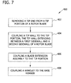
- Figure 7 is a flowchart of an exemplary method 400 for assembling blade extension assembly 100.
- method 400 includes on-site assembly of blade extension 100 at the location of wind turbine 10.
- Method 400 includes removing 402 tip end 118 from blade tip portion 120 of rotor blade 22 and coupling 404 tip wall 116 to blade tip portion 120, such that tip wall 116 extends between first sidewall 102 and second sidewall 104.
- Blade extension assembly 100 is coupled 406 to blade tip portion 120.
- blade extension assembly 100 is coupled 406 to blade tip portion 120 by inserting support rods 138 into cavity 110.
- support rods 138 are coupled to blade tip portion 120 with a plurality of shear pins 166 at least partially inserted through the blade tip portion 120 and the support rods 138.
- blade extension assembly 100 is coupled to blade tip portion 120 uptower with rotor blade 22 coupled to hub 20.
- rotor blade 22 is accessible using a man-basket, a crane, a ladder, or any suitable means of accessing rotor blade 22 with rotor blade 22 coupled to wind turbine 10.
- blade extension assembly 100 is coupled to rotor blade 22 with rotor blade 22 not coupled to wind turbine 10.
- Winglet 240 is optionally coupled 408 to base member 136, wherein winglet 240 extends substantially perpendicularly outward from base member 136.
- the above-described systems and methods facilitate an increase in the power production of an existing wind turbine, and facilitate a reduction in the generation of acoustic noise during operating of the existing wind turbine.
- the blade extension assembly coupled to an existing rotor blade facilitates an increase in the rotor blade length and surface area, thereby facilitating an increase in the power production of the wind turbine.
- the blade extension facilitates modifying the vortices that trail from the rotor blade, thereby facilitating reduced pressure fluctuations across a rotor blade surface that generate noise.
- the ability to retrofit existing rotor blades to facilitate an increase in the power production of a wind turbine eliminates the need to replace the rotor blade in an effort to increase power production. As such, the cost of upgrading a wind turbine to increase power generation is significantly reduced. Reducing such costs extends the operational life expectancies of wind turbine rotor blades.
- Exemplary embodiments of systems and methods for assembling a rotor blade extension for use in a wind turbine are described above in detail.
- the systems and methods are not limited to the specific embodiments described herein, but rather, components of systems and/or steps of the methods may be utilized independently and separately from other components and/or steps described herein.
- the methods may also be used in combination with other rotor blade improvement systems and methods, and are not limited to practice with only the wind turbine systems as described herein. Rather, the exemplary embodiment can be implemented and utilized in connection with many other rotor blade applications.
Landscapes
- Engineering & Computer Science (AREA)
- Life Sciences & Earth Sciences (AREA)
- Sustainable Development (AREA)
- Sustainable Energy (AREA)
- Chemical & Material Sciences (AREA)
- Combustion & Propulsion (AREA)
- Mechanical Engineering (AREA)
- General Engineering & Computer Science (AREA)
- Wind Motors (AREA)
Applications Claiming Priority (1)
| Application Number | Priority Date | Filing Date | Title |
|---|---|---|---|
| US12/569,251 US8328516B2 (en) | 2009-09-29 | 2009-09-29 | Systems and methods of assembling a rotor blade extension for use in a wind turbine |
Publications (3)
| Publication Number | Publication Date |
|---|---|
| EP2305999A2 true EP2305999A2 (de) | 2011-04-06 |
| EP2305999A3 EP2305999A3 (de) | 2014-03-05 |
| EP2305999B1 EP2305999B1 (de) | 2017-01-18 |
Family
ID=42983983
Family Applications (1)
| Application Number | Title | Priority Date | Filing Date |
|---|---|---|---|
| EP10178732.3A Not-in-force EP2305999B1 (de) | 2009-09-29 | 2010-09-23 | Systeme und Methoden zum Aufbau einer Rotorblattverlängerung zum Gebrauch in einer Windenergieanlage |
Country Status (5)
| Country | Link |
|---|---|
| US (1) | US8328516B2 (de) |
| EP (1) | EP2305999B1 (de) |
| CN (1) | CN102032099B (de) |
| DK (1) | DK2305999T3 (de) |
| ES (1) | ES2616317T3 (de) |
Cited By (6)
| Publication number | Priority date | Publication date | Assignee | Title |
|---|---|---|---|---|
| WO2012031976A1 (de) * | 2010-09-10 | 2012-03-15 | Wobben, Aloys | Abnehmbare rotorblattspitze |
| WO2014064088A1 (en) * | 2012-10-22 | 2014-05-01 | New World Energy Enterprises Ltd | A turbine blade system |
| EP3037655A1 (de) * | 2014-12-22 | 2016-06-29 | Siemens Aktiengesellschaft | Rotorblattverlängerung |
| WO2018019350A1 (en) * | 2016-07-29 | 2018-02-01 | Vestas Wind Systems A/S | Wind turbine blade having a lightning tip receptor |
| EP2778391A3 (de) * | 2013-03-14 | 2018-04-11 | General Electric Company | System und Verfahren zum Installieren eines Blatteinsatzes zwischen getrennten Abschnitten eines Rotorblattes |
| US11248588B2 (en) | 2016-07-29 | 2022-02-15 | Vestas Wind Systems A/S | Wind turbine blade having a lightning tip receptor |
Families Citing this family (36)
| Publication number | Priority date | Publication date | Assignee | Title |
|---|---|---|---|---|
| US8258645B2 (en) * | 2009-04-20 | 2012-09-04 | Barber Gerald L | Wind turbine with sail extensions |
| US8328516B2 (en) * | 2009-09-29 | 2012-12-11 | General Electric Company | Systems and methods of assembling a rotor blade extension for use in a wind turbine |
| US20120093627A1 (en) * | 2010-10-18 | 2012-04-19 | Clipper Windpower, Inc. | Method for site specific energy capture optimization through modular rotor blade tip extension |
| CN102200100A (zh) * | 2011-06-02 | 2011-09-28 | 东方电气集团东方汽轮机有限公司 | 风力发电机分体组装型叶片 |
| ES2401511B1 (es) * | 2011-07-06 | 2014-04-14 | Gamesa Innovation & Technology S.L. | Método de fabricación de palas de aerogeneradores de longitud variable. |
| US20130177433A1 (en) * | 2012-01-11 | 2013-07-11 | General Electric Company | Multi-material retrofitted wind turbine rotor blade and methods for making the same |
| US9399919B2 (en) | 2012-12-31 | 2016-07-26 | General Electric Company | Extension tip sleeve for wind turbine blade |
| GB201307066D0 (en) * | 2013-04-18 | 2013-05-29 | Airbus Operations Ltd | Winglet and braided composite spar |
| US20150003991A1 (en) * | 2013-06-28 | 2015-01-01 | General Electric Company | Modular extensions for wind turbine rotor blades |
| DE102014106529B4 (de) * | 2014-05-09 | 2016-02-04 | Senvion Gmbh | Reparaturverfahren für Vortexgenerator und ein Bausatz dafür |
| PL2998572T3 (pl) * | 2014-09-22 | 2017-02-28 | Best Blades Gmbh | Łopata śmigła wirnika turbiny wiatrowej |
| US10006436B2 (en) | 2014-12-18 | 2018-06-26 | General Electric Company | Wind turbine rotor blades with load-transferring exterior panels |
| US9869295B2 (en) * | 2015-05-07 | 2018-01-16 | General Electric Company | Attachment method to install components, such as tip extensions and winglets, to a wind turbine blade, as well as the wind turbine blade and component |
| US9869297B2 (en) | 2015-05-07 | 2018-01-16 | General Electric Company | Attachment method and system to install components, such as vortex generators, to a wind turbine blade |
| US9869296B2 (en) * | 2015-05-07 | 2018-01-16 | General Electric Company | Attachment method and system to install components, such as tip extensions and winglets, to a wind turbine blade |
| CN105065196B (zh) * | 2015-07-30 | 2016-11-23 | 中国大唐集团新能源股份有限公司 | 一种叶片加长型风机 |
| US10100805B2 (en) | 2015-10-12 | 2018-10-16 | General Electric Compant | Tip extension assembly for a wind turbine rotor blade |
| US10443579B2 (en) | 2016-11-15 | 2019-10-15 | General Electric Company | Tip extensions for wind turbine rotor blades and methods of installing same |
| US11098691B2 (en) | 2017-02-03 | 2021-08-24 | General Electric Company | Methods for manufacturing wind turbine rotor blades and components thereof |
| US10830206B2 (en) | 2017-02-03 | 2020-11-10 | General Electric Company | Methods for manufacturing wind turbine rotor blades and components thereof |
| US10495058B2 (en) * | 2017-02-21 | 2019-12-03 | General Electric Company | Joint assembly for rotor blade segments of a wind turbine |
| US10801469B2 (en) | 2017-11-07 | 2020-10-13 | General Electric Company | Wind blade joints with floating connectors |
| US10865769B2 (en) | 2017-11-21 | 2020-12-15 | General Electric Company | Methods for manufacturing wind turbine rotor blade panels having printed grid structures |
| US11668275B2 (en) | 2017-11-21 | 2023-06-06 | General Electric Company | Methods for manufacturing an outer skin of a rotor blade |
| US10913216B2 (en) | 2017-11-21 | 2021-02-09 | General Electric Company | Methods for manufacturing wind turbine rotor blade panels having printed grid structures |
| US11248582B2 (en) | 2017-11-21 | 2022-02-15 | General Electric Company | Multiple material combinations for printed reinforcement structures of rotor blades |
| US11040503B2 (en) | 2017-11-21 | 2021-06-22 | General Electric Company | Apparatus for manufacturing composite airfoils |
| US11390013B2 (en) | 2017-11-21 | 2022-07-19 | General Electric Company | Vacuum forming mold assembly and associated methods |
| US10821652B2 (en) | 2017-11-21 | 2020-11-03 | General Electric Company | Vacuum forming mold assembly and method for creating a vacuum forming mold assembly |
| US10773464B2 (en) | 2017-11-21 | 2020-09-15 | General Electric Company | Method for manufacturing composite airfoils |
| US10920745B2 (en) | 2017-11-21 | 2021-02-16 | General Electric Company | Wind turbine rotor blade components and methods of manufacturing the same |
| US11035339B2 (en) | 2018-03-26 | 2021-06-15 | General Electric Company | Shear web assembly interconnected with additive manufactured components |
| US10821696B2 (en) | 2018-03-26 | 2020-11-03 | General Electric Company | Methods for manufacturing flatback airfoils for wind turbine rotor blades |
| CN109014905B (zh) * | 2018-09-04 | 2024-04-02 | 深圳市源博旺科技有限公司 | 一种自动化风轮组装设备 |
| EP3867052B1 (de) | 2018-10-18 | 2023-06-21 | Vestas Wind Systems A/S | Verbesserungen im zusammenhang mit der windturbinenschaufelherstellung |
| GB202020710D0 (en) | 2020-12-30 | 2021-02-10 | Gen Electric | Method of joining segments of a composite component |
Family Cites Families (27)
| Publication number | Priority date | Publication date | Assignee | Title |
|---|---|---|---|---|
| NL9301910A (nl) * | 1993-11-04 | 1995-06-01 | Stork Prod Eng | Windturbine. |
| DE19743694C2 (de) * | 1997-10-02 | 2001-11-15 | Aloys Wobben | Rotorblatt und Windenergieanlage mit einem Rotorblatt |
| NZ511846A (en) * | 1998-12-09 | 2003-07-25 | Aloys Wobben | Reduction in the noise produced by a rotor blade of a wind turbine |
| US7059833B2 (en) * | 2001-11-26 | 2006-06-13 | Bonus Energy A/S | Method for improvement of the efficiency of a wind turbine rotor |
| ES2440218T3 (es) * | 2003-01-02 | 2014-01-28 | Wobben Properties Gmbh | Pala de rotor de turbina eólica con emisión de ruido reducida |
| DE10300284A1 (de) * | 2003-01-02 | 2004-07-15 | Aloys Wobben | Rotorblatt für eine Windenergieanlage |
| US8544800B2 (en) * | 2005-07-21 | 2013-10-01 | The Boeing Company | Integrated wingtip extensions for jet transport aircraft and other types of aircraft |
| US7690895B2 (en) * | 2005-07-29 | 2010-04-06 | General Electric Company | Multi-piece passive load reducing blades and wind turbines using same |
| US7458777B2 (en) * | 2005-09-22 | 2008-12-02 | General Electric Company | Wind turbine rotor assembly and blade having acoustic flap |
| US20070175134A1 (en) * | 2006-01-19 | 2007-08-02 | G.Mcneilus, Llc | Tilt-up support tower |
| US7654799B2 (en) * | 2006-04-30 | 2010-02-02 | General Electric Company | Modular rotor blade for a wind turbine and method for assembling same |
| US7959412B2 (en) * | 2006-09-29 | 2011-06-14 | General Electric Company | Wind turbine rotor blade with acoustic lining |
| US7713028B2 (en) * | 2006-11-27 | 2010-05-11 | Ning Liao | Turbine blade assembly |
| CN101622446B (zh) * | 2006-12-22 | 2011-12-28 | 维斯塔斯风力系统有限公司 | 带有设置小翼的转子叶片的风轮机及用于这种转子的叶片 |
| JP5242920B2 (ja) * | 2007-01-23 | 2013-07-24 | 株式会社日立製作所 | 風車用分割翼 |
| US7901189B2 (en) * | 2007-05-14 | 2011-03-08 | General Electric Company | Wind-turbine blade and method for reducing noise in wind turbine |
| ES2345583B1 (es) * | 2007-05-31 | 2011-07-28 | GAMESA INNOVATION & TECHNOLOGY, S.L. | Pala de aerogenerador con dispositivos anti-ruido. |
| US8167569B2 (en) * | 2007-12-21 | 2012-05-01 | General Electric Company | Structure and method for self-aligning rotor blade joints |
| US8231351B2 (en) * | 2007-12-27 | 2012-07-31 | General Electric Company | Adaptive rotor blade for a wind turbine |
| CA2703641A1 (en) * | 2008-01-14 | 2009-07-23 | Clipper Windpower, Inc. | A modular rotor blade for a power-generating turbine and a method for assembling a power-generating turbine with modular rotor blades |
| US20110158788A1 (en) * | 2008-08-31 | 2011-06-30 | Vestas Wind Systems A/S | A sectional blade |
| JP5249684B2 (ja) * | 2008-09-04 | 2013-07-31 | 三菱重工業株式会社 | 風車翼 |
| US8328516B2 (en) * | 2009-09-29 | 2012-12-11 | General Electric Company | Systems and methods of assembling a rotor blade extension for use in a wind turbine |
| EP2317124B1 (de) * | 2009-10-01 | 2018-08-08 | Vestas Wind Systems A/S | Windturbinenschaufel |
| EP2357357B1 (de) * | 2009-10-01 | 2016-11-09 | Vestas Wind Systems A/S | Windturbinenschaufel |
| US8083488B2 (en) * | 2010-08-23 | 2011-12-27 | General Electric Company | Blade extension for rotor blade in wind turbine |
| US8029241B2 (en) * | 2010-09-15 | 2011-10-04 | General Electric Company | Wind turbine rotor blade with aerodynamic winglet |
-
2009
- 2009-09-29 US US12/569,251 patent/US8328516B2/en not_active Expired - Fee Related
-
2010
- 2010-09-23 DK DK10178732.3T patent/DK2305999T3/en active
- 2010-09-23 EP EP10178732.3A patent/EP2305999B1/de not_active Not-in-force
- 2010-09-23 ES ES10178732.3T patent/ES2616317T3/es active Active
- 2010-09-29 CN CN201010512964.6A patent/CN102032099B/zh not_active Expired - Fee Related
Non-Patent Citations (1)
| Title |
|---|
| None |
Cited By (8)
| Publication number | Priority date | Publication date | Assignee | Title |
|---|---|---|---|---|
| WO2012031976A1 (de) * | 2010-09-10 | 2012-03-15 | Wobben, Aloys | Abnehmbare rotorblattspitze |
| US9371817B2 (en) | 2010-09-10 | 2016-06-21 | Wobben Properties Gmbh | Removable rotor blade tip |
| WO2014064088A1 (en) * | 2012-10-22 | 2014-05-01 | New World Energy Enterprises Ltd | A turbine blade system |
| EP2778391A3 (de) * | 2013-03-14 | 2018-04-11 | General Electric Company | System und Verfahren zum Installieren eines Blatteinsatzes zwischen getrennten Abschnitten eines Rotorblattes |
| EP3037655A1 (de) * | 2014-12-22 | 2016-06-29 | Siemens Aktiengesellschaft | Rotorblattverlängerung |
| WO2018019350A1 (en) * | 2016-07-29 | 2018-02-01 | Vestas Wind Systems A/S | Wind turbine blade having a lightning tip receptor |
| US10871150B2 (en) | 2016-07-29 | 2020-12-22 | Vestas Wind Systems A/S | Wind turbine blade having a lightning tip receptor |
| US11248588B2 (en) | 2016-07-29 | 2022-02-15 | Vestas Wind Systems A/S | Wind turbine blade having a lightning tip receptor |
Also Published As
| Publication number | Publication date |
|---|---|
| EP2305999A3 (de) | 2014-03-05 |
| ES2616317T3 (es) | 2017-06-12 |
| CN102032099B (zh) | 2014-05-07 |
| DK2305999T3 (en) | 2017-02-27 |
| US20110076149A1 (en) | 2011-03-31 |
| EP2305999B1 (de) | 2017-01-18 |
| US8328516B2 (en) | 2012-12-11 |
| CN102032099A (zh) | 2011-04-27 |
Similar Documents
| Publication | Publication Date | Title |
|---|---|---|
| US8328516B2 (en) | Systems and methods of assembling a rotor blade extension for use in a wind turbine | |
| US8303250B2 (en) | Method and apparatus for increasing lift on wind turbine blade | |
| DK178423B1 (en) | Rotor Blade Assembly | |
| EP2194267B1 (de) | Wurzelhülse für ein Blatt einer Windkraftanlage | |
| US20110142636A1 (en) | Expansion assembly for a rotor blade of a wind turbine | |
| US8317469B2 (en) | Wind turbine shroud | |
| US20110142676A1 (en) | Rotor blade assembly having an auxiliary blade | |
| EP2957765A1 (de) | Windturbinenschaufelspitzengelenk | |
| EP2141355A2 (de) | Windturbinenschaufeln mit mehreren Krümmungsraden | |
| US20120027588A1 (en) | Root flap for rotor blade in wind turbine | |
| EP3553307B1 (de) | Gezahnter geräuschreduzierer für ein windturbinenrotorblatt | |
| EP2204578A2 (de) | Zum Teil bogenförmiger Deckring für Windturbinenschaufeln | |
| EP2436924A1 (de) | Windenergieanalagevorrichtung | |
| US20110211952A1 (en) | Rotor blade for wind turbine | |
| JP4184847B2 (ja) | 風車装置及びそれを用いた風力発電装置 | |
| KR102493731B1 (ko) | 후류 확산을 향상시키도록 형상지워진 로터 블레이드 | |
| US20150118053A1 (en) | High efficiency vertical axis wind turbine apparatus | |
| EP4457432B1 (de) | Windenergieanlage | |
| CN113167212A (zh) | 经由其叶片尖端节段中的增加的预弯曲具有最大化的总体预弯曲的分段式转子叶片 | |
| EP2236819A1 (de) | Windmühle mit vertikaler achse | |
| KR20130069812A (ko) | 풍차 날개 및 이를 구비한 풍력 발전 장치 및 풍차 날개의 설계 방법 | |
| EP3085953A1 (de) | Windturbinenkuppel und montageverfahren | |
| KR20160026044A (ko) | 풍력 발전 장치용 허브의 공기 순환 시스템 및 이를 이용한 풍력 발전 장치 |
Legal Events
| Date | Code | Title | Description |
|---|---|---|---|
| PUAI | Public reference made under article 153(3) epc to a published international application that has entered the european phase |
Free format text: ORIGINAL CODE: 0009012 |
|
| AK | Designated contracting states |
Kind code of ref document: A2 Designated state(s): AL AT BE BG CH CY CZ DE DK EE ES FI FR GB GR HR HU IE IS IT LI LT LU LV MC MK MT NL NO PL PT RO SE SI SK SM TR |
|
| AX | Request for extension of the european patent |
Extension state: BA ME RS |
|
| PUAL | Search report despatched |
Free format text: ORIGINAL CODE: 0009013 |
|
| AK | Designated contracting states |
Kind code of ref document: A3 Designated state(s): AL AT BE BG CH CY CZ DE DK EE ES FI FR GB GR HR HU IE IS IT LI LT LU LV MC MK MT NL NO PL PT RO SE SI SK SM TR |
|
| AX | Request for extension of the european patent |
Extension state: BA ME RS |
|
| RIC1 | Information provided on ipc code assigned before grant |
Ipc: F03D 1/06 20060101AFI20140128BHEP |
|
| 17P | Request for examination filed |
Effective date: 20140905 |
|
| RBV | Designated contracting states (corrected) |
Designated state(s): AL AT BE BG CH CY CZ DE DK EE ES FI FR GB GR HR HU IE IS IT LI LT LU LV MC MK MT NL NO PL PT RO SE SI SK SM TR |
|
| 17Q | First examination report despatched |
Effective date: 20160229 |
|
| GRAP | Despatch of communication of intention to grant a patent |
Free format text: ORIGINAL CODE: EPIDOSNIGR1 |
|
| INTG | Intention to grant announced |
Effective date: 20160926 |
|
| INTG | Intention to grant announced |
Effective date: 20161004 |
|
| INTG | Intention to grant announced |
Effective date: 20161011 |
|
| GRAS | Grant fee paid |
Free format text: ORIGINAL CODE: EPIDOSNIGR3 |
|
| GRAA | (expected) grant |
Free format text: ORIGINAL CODE: 0009210 |
|
| AK | Designated contracting states |
Kind code of ref document: B1 Designated state(s): AL AT BE BG CH CY CZ DE DK EE ES FI FR GB GR HR HU IE IS IT LI LT LU LV MC MK MT NL NO PL PT RO SE SI SK SM TR |
|
| REG | Reference to a national code |
Ref country code: GB Ref legal event code: FG4D |
|
| REG | Reference to a national code |
Ref country code: CH Ref legal event code: EP |
|
| REG | Reference to a national code |
Ref country code: AT Ref legal event code: REF Ref document number: 863064 Country of ref document: AT Kind code of ref document: T Effective date: 20170215 |
|
| REG | Reference to a national code |
Ref country code: IE Ref legal event code: FG4D |
|
| REG | Reference to a national code |
Ref country code: DK Ref legal event code: T3 Effective date: 20170221 |
|
| REG | Reference to a national code |
Ref country code: DE Ref legal event code: R096 Ref document number: 602010039639 Country of ref document: DE |
|
| REG | Reference to a national code |
Ref country code: NL Ref legal event code: MP Effective date: 20170118 |
|
| REG | Reference to a national code |
Ref country code: LT Ref legal event code: MG4D |
|
| REG | Reference to a national code |
Ref country code: ES Ref legal event code: FG2A Ref document number: 2616317 Country of ref document: ES Kind code of ref document: T3 Effective date: 20170612 |
|
| REG | Reference to a national code |
Ref country code: AT Ref legal event code: MK05 Ref document number: 863064 Country of ref document: AT Kind code of ref document: T Effective date: 20170118 |
|
| PG25 | Lapsed in a contracting state [announced via postgrant information from national office to epo] |
Ref country code: NL Free format text: LAPSE BECAUSE OF FAILURE TO SUBMIT A TRANSLATION OF THE DESCRIPTION OR TO PAY THE FEE WITHIN THE PRESCRIBED TIME-LIMIT Effective date: 20170118 |
|
| PG25 | Lapsed in a contracting state [announced via postgrant information from national office to epo] |
Ref country code: NO Free format text: LAPSE BECAUSE OF FAILURE TO SUBMIT A TRANSLATION OF THE DESCRIPTION OR TO PAY THE FEE WITHIN THE PRESCRIBED TIME-LIMIT Effective date: 20170418 Ref country code: LT Free format text: LAPSE BECAUSE OF FAILURE TO SUBMIT A TRANSLATION OF THE DESCRIPTION OR TO PAY THE FEE WITHIN THE PRESCRIBED TIME-LIMIT Effective date: 20170118 Ref country code: GR Free format text: LAPSE BECAUSE OF FAILURE TO SUBMIT A TRANSLATION OF THE DESCRIPTION OR TO PAY THE FEE WITHIN THE PRESCRIBED TIME-LIMIT Effective date: 20170419 Ref country code: FI Free format text: LAPSE BECAUSE OF FAILURE TO SUBMIT A TRANSLATION OF THE DESCRIPTION OR TO PAY THE FEE WITHIN THE PRESCRIBED TIME-LIMIT Effective date: 20170118 Ref country code: IS Free format text: LAPSE BECAUSE OF FAILURE TO SUBMIT A TRANSLATION OF THE DESCRIPTION OR TO PAY THE FEE WITHIN THE PRESCRIBED TIME-LIMIT Effective date: 20170518 Ref country code: HR Free format text: LAPSE BECAUSE OF FAILURE TO SUBMIT A TRANSLATION OF THE DESCRIPTION OR TO PAY THE FEE WITHIN THE PRESCRIBED TIME-LIMIT Effective date: 20170118 |
|
| PG25 | Lapsed in a contracting state [announced via postgrant information from national office to epo] |
Ref country code: PT Free format text: LAPSE BECAUSE OF FAILURE TO SUBMIT A TRANSLATION OF THE DESCRIPTION OR TO PAY THE FEE WITHIN THE PRESCRIBED TIME-LIMIT Effective date: 20170518 Ref country code: LV Free format text: LAPSE BECAUSE OF FAILURE TO SUBMIT A TRANSLATION OF THE DESCRIPTION OR TO PAY THE FEE WITHIN THE PRESCRIBED TIME-LIMIT Effective date: 20170118 Ref country code: PL Free format text: LAPSE BECAUSE OF FAILURE TO SUBMIT A TRANSLATION OF THE DESCRIPTION OR TO PAY THE FEE WITHIN THE PRESCRIBED TIME-LIMIT Effective date: 20170118 Ref country code: SE Free format text: LAPSE BECAUSE OF FAILURE TO SUBMIT A TRANSLATION OF THE DESCRIPTION OR TO PAY THE FEE WITHIN THE PRESCRIBED TIME-LIMIT Effective date: 20170118 Ref country code: AT Free format text: LAPSE BECAUSE OF FAILURE TO SUBMIT A TRANSLATION OF THE DESCRIPTION OR TO PAY THE FEE WITHIN THE PRESCRIBED TIME-LIMIT Effective date: 20170118 Ref country code: BG Free format text: LAPSE BECAUSE OF FAILURE TO SUBMIT A TRANSLATION OF THE DESCRIPTION OR TO PAY THE FEE WITHIN THE PRESCRIBED TIME-LIMIT Effective date: 20170418 |
|
| REG | Reference to a national code |
Ref country code: FR Ref legal event code: PLFP Year of fee payment: 8 |
|
| REG | Reference to a national code |
Ref country code: DE Ref legal event code: R097 Ref document number: 602010039639 Country of ref document: DE |
|
| PG25 | Lapsed in a contracting state [announced via postgrant information from national office to epo] |
Ref country code: EE Free format text: LAPSE BECAUSE OF FAILURE TO SUBMIT A TRANSLATION OF THE DESCRIPTION OR TO PAY THE FEE WITHIN THE PRESCRIBED TIME-LIMIT Effective date: 20170118 Ref country code: RO Free format text: LAPSE BECAUSE OF FAILURE TO SUBMIT A TRANSLATION OF THE DESCRIPTION OR TO PAY THE FEE WITHIN THE PRESCRIBED TIME-LIMIT Effective date: 20170118 Ref country code: IT Free format text: LAPSE BECAUSE OF FAILURE TO SUBMIT A TRANSLATION OF THE DESCRIPTION OR TO PAY THE FEE WITHIN THE PRESCRIBED TIME-LIMIT Effective date: 20170118 Ref country code: CZ Free format text: LAPSE BECAUSE OF FAILURE TO SUBMIT A TRANSLATION OF THE DESCRIPTION OR TO PAY THE FEE WITHIN THE PRESCRIBED TIME-LIMIT Effective date: 20170118 Ref country code: SK Free format text: LAPSE BECAUSE OF FAILURE TO SUBMIT A TRANSLATION OF THE DESCRIPTION OR TO PAY THE FEE WITHIN THE PRESCRIBED TIME-LIMIT Effective date: 20170118 |
|
| PLBE | No opposition filed within time limit |
Free format text: ORIGINAL CODE: 0009261 |
|
| STAA | Information on the status of an ep patent application or granted ep patent |
Free format text: STATUS: NO OPPOSITION FILED WITHIN TIME LIMIT |
|
| PG25 | Lapsed in a contracting state [announced via postgrant information from national office to epo] |
Ref country code: SM Free format text: LAPSE BECAUSE OF FAILURE TO SUBMIT A TRANSLATION OF THE DESCRIPTION OR TO PAY THE FEE WITHIN THE PRESCRIBED TIME-LIMIT Effective date: 20170118 |
|
| 26N | No opposition filed |
Effective date: 20171019 |
|
| PG25 | Lapsed in a contracting state [announced via postgrant information from national office to epo] |
Ref country code: SI Free format text: LAPSE BECAUSE OF FAILURE TO SUBMIT A TRANSLATION OF THE DESCRIPTION OR TO PAY THE FEE WITHIN THE PRESCRIBED TIME-LIMIT Effective date: 20170118 |
|
| REG | Reference to a national code |
Ref country code: CH Ref legal event code: PL |
|
| GBPC | Gb: european patent ceased through non-payment of renewal fee |
Effective date: 20170923 |
|
| PG25 | Lapsed in a contracting state [announced via postgrant information from national office to epo] |
Ref country code: MC Free format text: LAPSE BECAUSE OF FAILURE TO SUBMIT A TRANSLATION OF THE DESCRIPTION OR TO PAY THE FEE WITHIN THE PRESCRIBED TIME-LIMIT Effective date: 20170118 |
|
| REG | Reference to a national code |
Ref country code: IE Ref legal event code: MM4A |
|
| REG | Reference to a national code |
Ref country code: BE Ref legal event code: MM Effective date: 20170930 |
|
| PG25 | Lapsed in a contracting state [announced via postgrant information from national office to epo] |
Ref country code: LU Free format text: LAPSE BECAUSE OF NON-PAYMENT OF DUE FEES Effective date: 20170923 |
|
| PG25 | Lapsed in a contracting state [announced via postgrant information from national office to epo] |
Ref country code: CH Free format text: LAPSE BECAUSE OF NON-PAYMENT OF DUE FEES Effective date: 20170930 Ref country code: LI Free format text: LAPSE BECAUSE OF NON-PAYMENT OF DUE FEES Effective date: 20170930 Ref country code: IE Free format text: LAPSE BECAUSE OF NON-PAYMENT OF DUE FEES Effective date: 20170923 Ref country code: GB Free format text: LAPSE BECAUSE OF NON-PAYMENT OF DUE FEES Effective date: 20170923 |
|
| REG | Reference to a national code |
Ref country code: FR Ref legal event code: PLFP Year of fee payment: 9 |
|
| PG25 | Lapsed in a contracting state [announced via postgrant information from national office to epo] |
Ref country code: BE Free format text: LAPSE BECAUSE OF NON-PAYMENT OF DUE FEES Effective date: 20170930 |
|
| PG25 | Lapsed in a contracting state [announced via postgrant information from national office to epo] |
Ref country code: MT Free format text: LAPSE BECAUSE OF NON-PAYMENT OF DUE FEES Effective date: 20170923 |
|
| PGFP | Annual fee paid to national office [announced via postgrant information from national office to epo] |
Ref country code: FR Payment date: 20180822 Year of fee payment: 9 Ref country code: DE Payment date: 20180821 Year of fee payment: 9 |
|
| PGFP | Annual fee paid to national office [announced via postgrant information from national office to epo] |
Ref country code: TR Payment date: 20180906 Year of fee payment: 9 Ref country code: DK Payment date: 20180824 Year of fee payment: 9 |
|
| PGFP | Annual fee paid to national office [announced via postgrant information from national office to epo] |
Ref country code: ES Payment date: 20181001 Year of fee payment: 9 |
|
| PG25 | Lapsed in a contracting state [announced via postgrant information from national office to epo] |
Ref country code: HU Free format text: LAPSE BECAUSE OF FAILURE TO SUBMIT A TRANSLATION OF THE DESCRIPTION OR TO PAY THE FEE WITHIN THE PRESCRIBED TIME-LIMIT; INVALID AB INITIO Effective date: 20100923 |
|
| PG25 | Lapsed in a contracting state [announced via postgrant information from national office to epo] |
Ref country code: CY Free format text: LAPSE BECAUSE OF NON-PAYMENT OF DUE FEES Effective date: 20170118 |
|
| PG25 | Lapsed in a contracting state [announced via postgrant information from national office to epo] |
Ref country code: MK Free format text: LAPSE BECAUSE OF FAILURE TO SUBMIT A TRANSLATION OF THE DESCRIPTION OR TO PAY THE FEE WITHIN THE PRESCRIBED TIME-LIMIT Effective date: 20170118 |
|
| REG | Reference to a national code |
Ref country code: DE Ref legal event code: R119 Ref document number: 602010039639 Country of ref document: DE |
|
| REG | Reference to a national code |
Ref country code: DK Ref legal event code: EBP Effective date: 20190930 |
|
| PG25 | Lapsed in a contracting state [announced via postgrant information from national office to epo] |
Ref country code: DE Free format text: LAPSE BECAUSE OF NON-PAYMENT OF DUE FEES Effective date: 20200401 Ref country code: AL Free format text: LAPSE BECAUSE OF FAILURE TO SUBMIT A TRANSLATION OF THE DESCRIPTION OR TO PAY THE FEE WITHIN THE PRESCRIBED TIME-LIMIT Effective date: 20170118 |
|
| PG25 | Lapsed in a contracting state [announced via postgrant information from national office to epo] |
Ref country code: FR Free format text: LAPSE BECAUSE OF NON-PAYMENT OF DUE FEES Effective date: 20190930 Ref country code: DK Free format text: LAPSE BECAUSE OF NON-PAYMENT OF DUE FEES Effective date: 20190930 |
|
| REG | Reference to a national code |
Ref country code: ES Ref legal event code: FD2A Effective date: 20210201 |
|
| PG25 | Lapsed in a contracting state [announced via postgrant information from national office to epo] |
Ref country code: ES Free format text: LAPSE BECAUSE OF NON-PAYMENT OF DUE FEES Effective date: 20190924 |
|
| PG25 | Lapsed in a contracting state [announced via postgrant information from national office to epo] |
Ref country code: TR Free format text: LAPSE BECAUSE OF NON-PAYMENT OF DUE FEES Effective date: 20190923 |
|
| P01 | Opt-out of the competence of the unified patent court (upc) registered |
Effective date: 20230522 |