EP2306005A2 - La méthode pour réduire des vibrations dans des éoliennes et l'éolienne mettant en oeuvre la méthode dite - Google Patents
La méthode pour réduire des vibrations dans des éoliennes et l'éolienne mettant en oeuvre la méthode dite Download PDFInfo
- Publication number
- EP2306005A2 EP2306005A2 EP10179698A EP10179698A EP2306005A2 EP 2306005 A2 EP2306005 A2 EP 2306005A2 EP 10179698 A EP10179698 A EP 10179698A EP 10179698 A EP10179698 A EP 10179698A EP 2306005 A2 EP2306005 A2 EP 2306005A2
- Authority
- EP
- European Patent Office
- Prior art keywords
- rotor
- wind
- degrees
- pitch
- wind turbine
- Prior art date
- Legal status (The legal status is an assumption and is not a legal conclusion. Google has not performed a legal analysis and makes no representation as to the accuracy of the status listed.)
- Granted
Links
Images



Classifications
-
- F—MECHANICAL ENGINEERING; LIGHTING; HEATING; WEAPONS; BLASTING
- F03—MACHINES OR ENGINES FOR LIQUIDS; WIND, SPRING, OR WEIGHT MOTORS; PRODUCING MECHANICAL POWER OR A REACTIVE PROPULSIVE THRUST, NOT OTHERWISE PROVIDED FOR
- F03D—WIND MOTORS
- F03D7/00—Controlling wind motors
- F03D7/02—Controlling wind motors the wind motors having rotation axis substantially parallel to the air flow entering the rotor
- F03D7/0264—Controlling wind motors the wind motors having rotation axis substantially parallel to the air flow entering the rotor for stopping; controlling in emergency situations
-
- F—MECHANICAL ENGINEERING; LIGHTING; HEATING; WEAPONS; BLASTING
- F03—MACHINES OR ENGINES FOR LIQUIDS; WIND, SPRING, OR WEIGHT MOTORS; PRODUCING MECHANICAL POWER OR A REACTIVE PROPULSIVE THRUST, NOT OTHERWISE PROVIDED FOR
- F03D—WIND MOTORS
- F03D7/00—Controlling wind motors
- F03D7/02—Controlling wind motors the wind motors having rotation axis substantially parallel to the air flow entering the rotor
- F03D7/022—Adjusting aerodynamic properties of the blades
- F03D7/0224—Adjusting blade pitch
-
- F—MECHANICAL ENGINEERING; LIGHTING; HEATING; WEAPONS; BLASTING
- F03—MACHINES OR ENGINES FOR LIQUIDS; WIND, SPRING, OR WEIGHT MOTORS; PRODUCING MECHANICAL POWER OR A REACTIVE PROPULSIVE THRUST, NOT OTHERWISE PROVIDED FOR
- F03D—WIND MOTORS
- F03D7/00—Controlling wind motors
- F03D7/02—Controlling wind motors the wind motors having rotation axis substantially parallel to the air flow entering the rotor
- F03D7/022—Adjusting aerodynamic properties of the blades
- F03D7/024—Adjusting aerodynamic properties of the blades of individual blades
-
- F—MECHANICAL ENGINEERING; LIGHTING; HEATING; WEAPONS; BLASTING
- F03—MACHINES OR ENGINES FOR LIQUIDS; WIND, SPRING, OR WEIGHT MOTORS; PRODUCING MECHANICAL POWER OR A REACTIVE PROPULSIVE THRUST, NOT OTHERWISE PROVIDED FOR
- F03D—WIND MOTORS
- F03D7/00—Controlling wind motors
- F03D7/02—Controlling wind motors the wind motors having rotation axis substantially parallel to the air flow entering the rotor
- F03D7/0296—Controlling wind motors the wind motors having rotation axis substantially parallel to the air flow entering the rotor to prevent, counteract or reduce noise emissions
-
- F—MECHANICAL ENGINEERING; LIGHTING; HEATING; WEAPONS; BLASTING
- F03—MACHINES OR ENGINES FOR LIQUIDS; WIND, SPRING, OR WEIGHT MOTORS; PRODUCING MECHANICAL POWER OR A REACTIVE PROPULSIVE THRUST, NOT OTHERWISE PROVIDED FOR
- F03D—WIND MOTORS
- F03D7/00—Controlling wind motors
- F03D7/02—Controlling wind motors the wind motors having rotation axis substantially parallel to the air flow entering the rotor
- F03D7/04—Automatic control; Regulation
- F03D7/042—Automatic control; Regulation by means of an electrical or electronic controller
-
- F—MECHANICAL ENGINEERING; LIGHTING; HEATING; WEAPONS; BLASTING
- F03—MACHINES OR ENGINES FOR LIQUIDS; WIND, SPRING, OR WEIGHT MOTORS; PRODUCING MECHANICAL POWER OR A REACTIVE PROPULSIVE THRUST, NOT OTHERWISE PROVIDED FOR
- F03D—WIND MOTORS
- F03D7/00—Controlling wind motors
- F03D7/02—Controlling wind motors the wind motors having rotation axis substantially parallel to the air flow entering the rotor
- F03D7/0264—Controlling wind motors the wind motors having rotation axis substantially parallel to the air flow entering the rotor for stopping; controlling in emergency situations
- F03D7/0268—Parking or storm protection
-
- F—MECHANICAL ENGINEERING; LIGHTING; HEATING; WEAPONS; BLASTING
- F03—MACHINES OR ENGINES FOR LIQUIDS; WIND, SPRING, OR WEIGHT MOTORS; PRODUCING MECHANICAL POWER OR A REACTIVE PROPULSIVE THRUST, NOT OTHERWISE PROVIDED FOR
- F03D—WIND MOTORS
- F03D7/00—Controlling wind motors
- F03D7/02—Controlling wind motors the wind motors having rotation axis substantially parallel to the air flow entering the rotor
- F03D7/028—Controlling wind motors the wind motors having rotation axis substantially parallel to the air flow entering the rotor controlling wind motor output power
- F03D7/0284—Controlling wind motors the wind motors having rotation axis substantially parallel to the air flow entering the rotor controlling wind motor output power in relation to the state of the electric grid
-
- F—MECHANICAL ENGINEERING; LIGHTING; HEATING; WEAPONS; BLASTING
- F05—INDEXING SCHEMES RELATING TO ENGINES OR PUMPS IN VARIOUS SUBCLASSES OF CLASSES F01-F04
- F05B—INDEXING SCHEME RELATING TO WIND, SPRING, WEIGHT, INERTIA OR LIKE MOTORS, TO MACHINES OR ENGINES FOR LIQUIDS COVERED BY SUBCLASSES F03B, F03D AND F03G
- F05B2270/00—Control
- F05B2270/30—Control parameters, e.g. input parameters
- F05B2270/32—Wind speeds
-
- F—MECHANICAL ENGINEERING; LIGHTING; HEATING; WEAPONS; BLASTING
- F05—INDEXING SCHEMES RELATING TO ENGINES OR PUMPS IN VARIOUS SUBCLASSES OF CLASSES F01-F04
- F05B—INDEXING SCHEME RELATING TO WIND, SPRING, WEIGHT, INERTIA OR LIKE MOTORS, TO MACHINES OR ENGINES FOR LIQUIDS COVERED BY SUBCLASSES F03B, F03D AND F03G
- F05B2270/00—Control
- F05B2270/30—Control parameters, e.g. input parameters
- F05B2270/321—Wind directions
-
- F—MECHANICAL ENGINEERING; LIGHTING; HEATING; WEAPONS; BLASTING
- F05—INDEXING SCHEMES RELATING TO ENGINES OR PUMPS IN VARIOUS SUBCLASSES OF CLASSES F01-F04
- F05B—INDEXING SCHEME RELATING TO WIND, SPRING, WEIGHT, INERTIA OR LIKE MOTORS, TO MACHINES OR ENGINES FOR LIQUIDS COVERED BY SUBCLASSES F03B, F03D AND F03G
- F05B2270/00—Control
- F05B2270/30—Control parameters, e.g. input parameters
- F05B2270/326—Rotor angle
-
- F—MECHANICAL ENGINEERING; LIGHTING; HEATING; WEAPONS; BLASTING
- F05—INDEXING SCHEMES RELATING TO ENGINES OR PUMPS IN VARIOUS SUBCLASSES OF CLASSES F01-F04
- F05B—INDEXING SCHEME RELATING TO WIND, SPRING, WEIGHT, INERTIA OR LIKE MOTORS, TO MACHINES OR ENGINES FOR LIQUIDS COVERED BY SUBCLASSES F03B, F03D AND F03G
- F05B2270/00—Control
- F05B2270/30—Control parameters, e.g. input parameters
- F05B2270/329—Azimuth or yaw angle
-
- Y—GENERAL TAGGING OF NEW TECHNOLOGICAL DEVELOPMENTS; GENERAL TAGGING OF CROSS-SECTIONAL TECHNOLOGIES SPANNING OVER SEVERAL SECTIONS OF THE IPC; TECHNICAL SUBJECTS COVERED BY FORMER USPC CROSS-REFERENCE ART COLLECTIONS [XRACs] AND DIGESTS
- Y02—TECHNOLOGIES OR APPLICATIONS FOR MITIGATION OR ADAPTATION AGAINST CLIMATE CHANGE
- Y02E—REDUCTION OF GREENHOUSE GAS [GHG] EMISSIONS, RELATED TO ENERGY GENERATION, TRANSMISSION OR DISTRIBUTION
- Y02E10/00—Energy generation through renewable energy sources
- Y02E10/70—Wind energy
- Y02E10/72—Wind turbines with rotation axis in wind direction
Definitions
- the present application relates generally to methods for reducing vibrations occurring in wind turbines. More particularly, the present application relates to methods for reducing the vibrations in wind turbines in situations where yawing of the wind turbine, i.e., rotating of a wind turbine nacelle about the tower axis, is not possible.
- Wind power plants also called wind farms or wind parks, include several wind turbines installed relatively close to each other in a defined area.
- One phenomenon known to occur in such wind farms is so-called vortex shedding.
- wind flowing around the tower of a wind turbine creates a von Karman vortex street downstream of the wind turbine tower.
- the turbine may start oscillating perpendicular to the wind direction. Such oscillations may then yield stresses in structural components of the wind turbine.
- a method for reducing vibrations of a wind turbine in a situation where yawing of a wind rotor of said wind turbine is at least temporarily not possible.
- the method includes adjusting a first pitch angle of a first rotor blade and a second pitch angle of a second rotor blade such that the first and second pitch angles differ by at least 30 degrees.
- a method for reducing vibrations of a wind turbine during yaw-incapability includes adjusting a first and a second rotor blade to different pitch angles, the pitch angles of the first and second rotor blades differing by at least 45 degrees.
- a wind turbine includes a first and a second rotor blade mounted to a rotor hub, each of the rotor blades being rotatable about a pitch axis for adjustment of its respective pitch angle, a pitch drive system adapted to adjust the pitch angles of each rotor blade, and a wind turbine controller adapted to control the pitch drive system to adjust, during a situation in which yawing of the wind turbine is at least temporarily not possible, a first pitch angle of the first rotor blade and a second pitch angle of the second rotor blade such that the first and second pitch angles differ by at least 30 degrees.
- Fig. 1 is a schematic front view of a wind turbine 100 having three rotor blades 140, 150, 160.
- the embodiments and examples described herein are not limited to wind turbines with three rotor blades but may be practiced also with wind turbines having a different number of rotor blades, in particular also only two rotor blades but also four or more rotor blades.
- the three rotor blades 140, 150 160 are arranged in a rotor blade plane around a rotor hub 130 which is attached to a nacelle 120 of the wind turbine.
- wind turbine rotors may have a cone shape so that the pitch axes of the rotor blades are not exactly aligned within a plane but rather form a flat cone.
- Such embodiments in which the axes of the blades are arranged on a cone rather than in a plane are nevertheless capable of practicing the embodiments described herein. Therefore, whenever reference to the rotor blade plane is made, cone-shaped embodiments are also embraced thereby. In both the plane and the cone-shaped embodiments, the angle between two adjacent rotor blades is typically equal and, in the specific embodiment shown, 120 degrees.
- Each of the rotor blades 140, 150, 160 is rotatable about its pitch axis (e.g., pitch axis 146 for rotor blade 140).
- the lines A-A, B-B, C-C denote top side views along the rotor blade axis shown in Fig. 2 .
- the nacelle 120 is mounted on top of tower 110.
- nacelle 120 is rotatable about a vertical axis 115 of tower 110 by means of a yaw drive 250.
- the wind rotor i.e. rotor hub 130 and the rotor blades 140 mounted thereto, may be aligned with the wind direction so that the rotor blade plane is oriented substantially perpendicular to the wind direction.
- yaw drive 250 is energized by power supplied by a utility grid to which wind turbine 100 is connected. In the event of a grid loss, for example, yaw drive 250 has no sufficient power supply and, thus, is disabled to align the wind rotor with respect to the wind direction. Due to such misalignment, vortex shedding may occur as explained above.
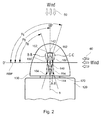
- Fig. 2 is a superimposed top side view of the wind turbine shown in Fig. 1 .
- Rotor axis 6 of the turbine extends substantially coaxially with rotor shaft 170 and substantially perpendicular to the rotor blade plane RBP in which the rotor blades are arranged.
- the rotor hub 130 is rotatably attached to nacelle 120.
- Side sectional views of all three rotor blades 140, 150 160 along lines A-A, B-B and C-C are superimposedly shown on top of rotor hub 130. It will be understood that each sectional view represents the moment at which the respective rotor blade has reached its top position.
- the pitch angles Pa, Pb, Pc of the three rotor blades 140,150, and 160, respectively, are shown in Fig. 2 .
- the three pitch angles Pa, Pb, and Pc will be identical or differ from each other only by a few degrees.
- Pitch angles Pa, Pb, Pc are shown different for clarification purposes only.
- Each of the rotor blades 140, 150, 160 has a leading edge 142, 152, 162 and a trailing edge 144, 154, 164.
- the pitch angle is defined as follows.
- a rotor blade position is defined to have a pitch angle of 0 degrees if the leading and trailing edges of the rotor blade are located within the rotor blade plane RBP (i.e., the leading edge facing left and the trailing edge facing right in Fig. 2 ).
- RBP rotor blade plane
- a positive blade angle is gained with +90 degrees being the position Pa shown for sectional view A-A of blade 140.
- the leading edge 142 and the trailing edge 144 are now aligned with rotor axis 6.
- the pitch angles Pb and Pc shown in Fig. 2 are also positive with Pb being smaller and Pc being larger than +90 degrees.
- the rotor blade has a pitch angle of +180 degrees (not shown) if its leading edge faces right and its trailing edge faces left in Fig. 2 along the rotor blade plane RBP. Pitch angles larger than +180 degrees will result in the leading edge facing toward the nacelle 120. If the rotor blade is rotated counterclockwise, i.e. the leading edge facing toward the nacelle 120, the pitch angle assumes negative values. For example -90 degrees pitch angle corresponds to a position where the trailing edge 144 faces toward the nose of rotor hub 130 and leading edge 142 faces toward nacelle 120. Accordingly, any pitch angle may be described by a positive and a negative value, for example +270 degrees being the same position as -90 degrees. This is shown as an example in Fig. 3 with respect to rotor blade 140. The positions of the rotor blades for other pitch angles can be obtained from the definitions given above.
- the +90 degree pitch angle Pa shown in Fig. 2 for rotor blade 140 is also called the feathered position of the rotor blade.
- the rotor blade does not extract a substantial amount of energy from the wind and may even result in aerodynamical braking of the wind rotor. Therefore, the rotor blades 140, 150, 160 are usually brought into feathered position when the turbine is idling and no power is generated.
- the foregoing is only true as long as the wind direction is substantially perpendicular to rotor blade plane RBP as indicated by the broken arrows 50 in Fig. 2 . In a situation where yawing of the wind turbine is at least temporarily not possible, e.g.
- rotor blade plane RBP may be misaligned with respect to the wind direction as indicated by the full arrows 60 in Fig. 2 .
- rotor blade plane RBP is misaligned by 90 degrees with respect to the wind direction 60.
- rotor blade plane RBP is parallel to the wind direction 60.
- vortex shedding is enhanced if all three rotor blades are in the feathered position.
- fore-aft oscillations or vibrations along rotor axis 6, are induced by vortex shedding.
- vibrations in other spatial directions may be induced by the vortex shedding and may vary depending upon the misalignment between the rotor blade plane RBP and the wind direction. The same phenomenon may also occur if one or more of the rotor blades have a pitch angle of - 90 degrees. Therefore, the aforementioned oscillations and vibrations may also occur during situations where the wind rotor is idling with the blades having a pitch angle of -90 degrees or with some blades having a pitch angle of +90 degrees and some having a pitch angle of -90 degrees.
- a first pitch angle Pa of a first rotor blade 140 and a second pitch angle Pb of a second rotor blade 150 are adjusted such that the first and second pitch angles Pa, Pb differ by at least 30 degrees.
- the first pitch angle Pa may be set to -90 degrees and the second pitch angle Pb may be set to +30 degrees. Due to the large difference between the first and second pitch angles, the effects caused by vortex shedding are considerably reduced. In particular, vibrations in the fore-aft direction of rotor hub 130 (in the direction or rotor axis 6) are dampened. Thus, the vibrational loads on rotor shaft 170 and other drive train components (e.g., gear box 230 and generator 240 shown in Fig.
- this method is particularly useful in situations where yawing of the wind rotor is at least temporarily not possible, such as during a grid loss.
- the wind rotor may be idling for the duration of the grid loss and the turbine is safeguarded against the adverse effects of vortex shedding.
- the vibration damping effect results from a considerable difference in pitch angles. Therefore, the first and second pitch angles may differ by at least 45 degrees.
- the damping effect in a specific direction is improved when the cross-sectional area of the rotor blades facing in this direction is enlarged.
- damping of vibrations in a specif direction is improved when the broad side of the blade faces this direction since the air drag of the blade will damp vibrations in this direction.
- the blades are set to different pitch angles so that damping occurs under any circumstances, and in particular for varying wind direction.
- a third rotor blade 160 may be part of the vibration-reducing concept described above.
- the third pitch angle Pc of the third rotor blade 160 is adjusted such that Pc is considerably different from the first and second pitch angles Pa and Pb.
- the third pitch angle Pc may differ from the first and second pitch angles Pa, Pb by at least 30 degrees, respectively.
- Fig. 3 is a superimposed top side view of the wind turbine shown in Fig. 1 . In the embodiment shown in Fig.
- the first rotor blade 140 has a pitch angle Pa of -90 degrees
- the second rotor blade 150 has a pitch angle of +30 degrees
- the third rotor blade 160 has a pitch angle Pc of + 150 degrees.
- the angular difference between the first and second pitch angles Pa, Pb is 120 degrees when measured in clockwise direction
- Pc is 120 degrees when measured in clockwise direction and between the first and third pitch angles Pa
- Pc is 120 degrees when measured in clockwise direction.
- other values for the pitch angles and the angular differences therebetween may be chosen in accordance with the circumstances so that the positions have an angular difference that is either equivalent or not equivalent.
- the first pitch angle Pa is -90 degrees
- the second pitch angle Pb is +45 degrees
- the third pitch angle Pc is zero degrees
- the first pitch angle Pa is +90 degrees
- the second pitch angle Pb is -30 degrees
- the third pitch angle Pc is -150 degrees.
- some embodiments employ even larger angular differences than only 30 degrees in which the third pitch angle differs in clockwise direction from the first and second pitch angles by at least 45 degrees, respectively.
- Even larger differences may be used between the first, second and third pitch angles Pa, Pb, Pc, respectively, such as 60 degrees, 80 degrees, 90 degrees or 120 degrees.
- the difference in clockwise direction between the first and second pitch angle Pa, Pb may in the range from 30 to 150 degrees, particularly 45 to 120 degrees, more particularly 60 to 90 degrees.
- the difference in clockwise direction between the second and third pitch angles Pb, Pc is in the range from 30 to 120 degrees, particularly 45 to 105 degrees, and more particularly 60 to 90 degrees.
- the difference in clockwise direction between the first and third pitch angles Pa, Pc is in the range from 60 to 270 degrees, particularly 90 to 240 degrees, more particularly 120 to 180 degrees in some embodiments.
- at least one of the pitch angles is in the range from 0 degrees up to, but not including, 180 degrees and at least one of the pitch angles is in the range from 180 degrees up to, but not including, 360 degrees.
- one of the pitch angles is set to zero degrees.
- a specific embodiment of a method 400 as described above is shown in the flow diagram of Fig. 4 .
- the wind turbine is continuously monitored to determine whether yawing of the wind turbine is temporarily not possible at decision block 405.
- the method proceeds to adjust the pitch angles of the rotor blades and set them to -35 degrees, zero degrees, and +35 degrees in order to reduce vibrations, in particular fore-aft vibrations due to vortex shedding at block 410.
- the particular pitch angles are, however, only examples and different pitch angle values may be used.
- a loop 415 it is monitored whether the grid loss condition still exists. As long as the inability to power the yaw drive exists, the setting of the pitch angles is maintained.
- wind turbines include an emergency power supply, such as batteries, accumulators, capacitors or the like, which enable pitching of the blades in situations where the grid is not available as a power supply.
- the described adjustment of the pitch angles may be effected by the emergency power supply.
- the emergency power supply has limited storage capacity and may be exhausted by repeatedly adjusting the pitch angles. Therefore, the pitch angles will typically be adjusted once to values that are optimized for varying wind conditions. With such a pitch angle setting, the turbine is in a safe state even for varying wind conditions. For example, such a safe setting may be the one shown in Fig. 3 .
- the wind turbine resumes normal operation 420 once the wind turbine is able to yaw.
- bringing the wind turbine back to normal operation involves specific wake-up procedures.
- the pitch angles may still be adjusted during the period of yaw-incapability without exhausting the emergency power supply. In such an event, a change in wind direction may render another pitch angle setting more preferable in view of vibration damping. Since the grid is available as a power supply for the pitch drive, the pitch angles may be adjusted to optimize vibration damping under the actual conditions.
- normal operation of the wind turbine may only be resumed after repair or replacement of the yaw system. In such a scenario, normal operation will not be resumed but the method will include repair or replacement of the defective parts. Thereafter, the wind turbine will be restarted according to usual procedure.
- the pitch angle differences will be chosen to reduce the vibrations induced by vortex shedding and/or similar phenomena. Therefore, the results of different pitch angle combinations may be monitored over time and correlated with the respective wind conditions, in particular wind direction and wind speed, at the time the pitch angle combination was employed.
- vibration detectors may sense vibrations in different parts of the turbine, for example tower vibrations, rotor shaft vibrations or the like. Also, the vibration detectors may sense vibrations in different spatial directions, for example in two or three mutually orthogonal directions. The foregoing measures allow collection of data and establishing empiric relationships which may be applied for controlling the turbines in situations of yaw-incapability.
- the wind rotor may be parked in a position in which none of the rotor blades is positioned in the vicinity of the tower 110 of the wind turbine 100. This includes positions in which the blade is in front of the tower, or behind the tower, or near the tower. In particular, vortex shedding may as well occur with the blade being in front or behind the tower with respect to wind direction.
- the terms "parking" or "parked” refer to locking the wind rotor in such position in contrast to allow idling of the wind rotor.
- the wind rotor may be locked in the desired position by applying a brake.
- the reason for parking the wind rotor in the described position is that the vortex-induced oscillations may be amplified when the rotor is parked with one blade in the vicinity of the tower, i.e. with one blade pointing down. This amplification of the oscillations may be due to a lower damping of the rotor blade being in the vicinity of the tower and/or an aerodynamical effect of the vortices on this blade.
- a rotor blade will typically be considered to be parked in the vicinity of the tower if its pitch axis is downward pointing and deviates from the tower axis within an angular range of - 15 degrees to +15 degrees.
- upward and downward may be understood relative to the horizon or, stated otherwise, the upward direction is along the tower axis from tower base to nacelle whereas the downward direction is from nacelle to tower base.
- the wind rotor is parked in a position so that none of the blades is positioned in front of, behind or near the tower.
- the wind rotor is rotated about the rotor axis into a position in which none of the rotor blades is positioned in the vicinity of a tower of the wind turbine.
- the amplification can be avoided.
- a wind rotor with three rotor blades is parked in a position in which one rotor blade is pointing upward and a pitch axis of the rotor blade forms an angle in the range of +15 degrees to -15 degrees, particularly + 10 degrees to -10 degrees, more particularly +5 degrees to -5 degrees, with a longitudinal axis of the wind turbine tower.
- a pitch axis of the rotor blade forms an angle in the range of +15 degrees to -15 degrees, particularly + 10 degrees to -10 degrees, more particularly +5 degrees to -5 degrees, with a longitudinal axis of the wind turbine tower.
- Fig. 1 where rotor blade 140 is pointing upward and is aligned with the tower axis 115, i.e. the angle between the rotor blade pitch axis 146 and the tower axis is about zero degrees.
- the pitch angle of the rotor blade closest to the tower may be adjusted in a way that it is less prone of picking up vortex-shedding excitation.
- the pitch angle of the rotor blade closest to the tower may be adjusted such that the broad side of the rotor blade is substantially perpendicular to the actual and/or anticipated wind direction.
- the described positioning of the wind rotor may be applied independent of the pitch angle setting and will still provide some reduction of the vibrations induced by vortex shedding.
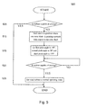
- Fig. 5 is a flow diagram of a method 500 according to a further embodiment of the method described above. Similar to Fig. 4 , yawing capability of the wind turbine is continuously monitored at decision block 505. In the event grid loss or any other situation affecting yawing capability is detected, the method proceeds to park the wind rotor in a position in which one of the rotor blades points upward with respect to the rotor shaft in order to avoid amplification of induced vibrations in block 510. Subsequently, the first pitch angle is set to -90 degrees, the second pitch angle is set to 30 degrees, and the third pitch angle is set to 150 degrees in block 515 to further reduce vibrations. As described above, the adjustment of the pitch angles may be effected by the emergency power supply.
- the pitch angles will be adjusted only once to save energy of the emergency power supply.
- a loop 520 it is monitored whether the condition still exists. As long as the inability for powering the yaw drive exists, the parking position of the wind rotor and the setting of the pitch angles are maintained.
- the turbine detects that the grid is available again or the wind turbine is otherwise able to yaw again, normal operation of the turbine will be resumed at block 525.
- bringing the wind turbine back to normal operation involves specific wake-up procedures which may be executed.
- the pitch angles of the first, second and third rotor blades differ by at least 45 degrees, respectively.
- the vibrations are not only reduced in one spatial direction, e.g. the fore-aft direction, but are also reduced in at least one further direction orthogonal to the axial direction of the rotor shaft.
- the pitch angles of the rotor blades are set to values so that vibration damping occurs in three mutually orthogonal spatial directions.
- the foregoing types of vibrations are only non-limiting examples and the embodiments of the present invention relate in general to vibration reduction during events of yaw-incapability. Accordingly, the embodiments of the present invention may be applied to reduce vibrations of wind turbine components in general.
- Such wind turbine components include, but are not limited to, tower 110, nacelle 120, rotor hub, 130, rotor blades 140, 150, 160, rotor shaft 170, gear box 230, or generator 240.
- the vibration reduction is achieved by adjusting the pitch angles of the rotor blades as described herein in connection with the various embodiments of the present invention.
- the specific settings will be empirically obtained because they depend on the specific conditions at the wind farm site and the location of the turbine within the wind farm. As a basis for the empiric control strategy, at least one variable will be monitored.
- the variable will be a tower vibration, a fore-aft vibration of the wind rotor, a wind direction, a wind speed, a yaw angle offset, a rotor position or any combination thereof.
- other environmental or turbine parameters may also be monitored and correlated with the vibrational state of the turbine.
- the pitch angle setting of the first, second and third rotor blades will be based on the determined variable(s) in order to reduce vibration.
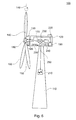
- Fig. 6 is a side view of a wind turbine 100 according to an embodiment of the present invention.
- Wind turbine 100 has first, second and third rotor blades 140, 150, 160 which are mounted to rotor hub 130. As indicated in Fig. 6 , each of the rotor blades is rotatable about a pitch axis, e.g., axis 146 for rotor blade 140, for adjustment of its respective pitch angle.
- the wind turbine further includes a pitch drive system 180 which is adapted to adjust the pitch angles of each rotor blade 140, 150, 160.
- pitch drive system 180 may include electric servomotors located at each of the rotor blades so that independent pitch angle adjustment of each rotor blade is allowed.
- an emergency power supply 185 e.g. a battery pack, accumulators or capacitors, are located within hub 130. Emergency power supply 185 is connected with pitch drive system 180 and adapted to supply the pitch drive system with power in the event power supply from the grid is not available.
- wind turbine 100 includes a wind turbine controller 190.
- wind turbine controller 190 is a specifically adapted computer system that is connected to one or more sensors. Thus, wind turbine controller 190 may continuously monitor the environmental condition in the vicinity of the wind turbine and the condition of the wind turbine. On the basis of these data, wind turbine controller 190 then determines whether any turbine parameters, e.g. pitch angles, yaw angle, generator torque, should be adjusted.
- wind turbine controller 190 is connected to a first vibration detector 200 which is adapted to detect vibrations in a fore-aft direction of the nacelle 120. Additionally or alternatively, first vibration detector 200 may be adapted to detect lateral vibrations of the nacelle 120. For example, vibration detector 200 may be directly mounted to a main frame or a wall of nacelle 120. In other embodiments, vibration detector 200 may be mounted to rotor hub 130. Also, vibration detector 200 may be adapted to detect vibrations in other spatial directions, for example in the direction of the tower axis.
- wind turbine controller 190 is connected to a further vibration sensor 210 located in tower 110.
- Vibration sensor 210 is adapted to detect tower vibrations in mutually orthogonal spatial directions, typically vibrations in directions orthogonal to the tower axis, and to report the detected vibrations to controller 190.
- wind turbine controller 190 is connected to at least one vibration detector adapted to sense the vibrations of at least one wind turbine component.
- controller 190 has an overview of the vibrational state of the wind turbine and may determine detrimental vibrations such as fore-aft vibrations that may harm turbine components such as rotor shaft 170, gear box 230 and generator 240.
- controller 190 is connected to a wind sensor 220 which is adapted to detect wind direction and wind speed.
- wind sensor 220 may include an anemometer and a wind vane.
- the vibrational state of the turbine can be correlated to the wind data collected by controller 190 either by controller 190 itself or in a control center to which the data are reported.
- the position of the wind rotor i.e. the orientation of the rotor blades 140, 150, 160 with respect to the rotor axis 6, may be used as an input parameter for the control strategy of wind turbine controller 190.
- an empiric control strategy i.e. specific pitch angle settings for specific wind conditions, may be determined and implemented in wind turbine controller 190.
- controller 190 may adjust the pitch angles of the rotor blades according to the empiric control strategy depending on the wind conditions detected by wind sensor 220.
- self-learning algorithms may be implemented in controller 190 so that the pitch angle settings are optimized for the current wind conditions during situations in which yawing is at least temporarily not possible but pitch angle adjustment is still possible, e.g. when the yaw system is out of order but the grid is available.
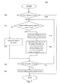
- Fig. 7 is a flow diagram of a method 700 as it may be performed by a wind turbine as shown in Fig. 6 .
- yawing of the wind turbine is continuously monitored at decision block 705.
- the method proceeds to determine wind speed, wind direction and yaw angle offset, i.e. the misalignment between the wind direction and the rotor blade plane.
- the pitch angles are set to values that reduce vibrations in at least two mutually orthogonal spatial directions at block 720.
- vibration damping is improved for the actual environmental conditions.
- the pitch angles are adjusted to reduce vibrations not only in two but also in three mutually orthogonal spatial directions. Thus, vibration damping is enhanced.
- an alternative procedure is applied if it is determined at decision block 710 that the grid is not available. In this event, the method proceeds with adjusting the pitch angles of the blades to a safe setting at block 730.
- a safe setting would be a combination of pitch angles that are adapted for damping vibrations regardless of the wind direction. Such a setting may, for example, be the setting shown in Fig. 3 . Since the grid is not available during this operation, the pitch angle adjustment is typically made by the emergency power supply.
- the pitch angles are only adjusted once, namely to the safe setting, and then not altered during the grid loss. Subsequently, the capability of yawing the wind turbine is monitored to determine whether the yaw-incapability of the turbine still exists at decision block 730 in either case. If yawing is still not possible, the method returns to decision block 710 and proceeds from thereon as described above. If it is detected in decision block 730 that the turbine is again capable of yawing, the wind turbine resumes normal operation according to block 735, which typically involves executing specific wake-up procedures as described above.
Landscapes
- Engineering & Computer Science (AREA)
- Life Sciences & Earth Sciences (AREA)
- Sustainable Development (AREA)
- Sustainable Energy (AREA)
- Chemical & Material Sciences (AREA)
- Combustion & Propulsion (AREA)
- Mechanical Engineering (AREA)
- General Engineering & Computer Science (AREA)
- Physics & Mathematics (AREA)
- Fluid Mechanics (AREA)
- Wind Motors (AREA)
Applications Claiming Priority (1)
| Application Number | Priority Date | Filing Date | Title |
|---|---|---|---|
| US12/570,396 US8360723B2 (en) | 2009-09-30 | 2009-09-30 | Method for reducing vibrations in wind turbines and wind turbine implementing said method |
Publications (3)
| Publication Number | Publication Date |
|---|---|
| EP2306005A2 true EP2306005A2 (fr) | 2011-04-06 |
| EP2306005A3 EP2306005A3 (fr) | 2014-02-19 |
| EP2306005B1 EP2306005B1 (fr) | 2016-09-21 |
Family
ID=42984058
Family Applications (1)
| Application Number | Title | Priority Date | Filing Date |
|---|---|---|---|
| EP10179698.5A Active EP2306005B1 (fr) | 2009-09-30 | 2010-09-24 | Méthode pour réduire les vibrations dans les éoliennes et éolienne mettant en oeuvre la dite méthode |
Country Status (5)
| Country | Link |
|---|---|
| US (1) | US8360723B2 (fr) |
| EP (1) | EP2306005B1 (fr) |
| CN (1) | CN102032110B (fr) |
| DK (1) | DK2306005T3 (fr) |
| ES (1) | ES2599353T3 (fr) |
Cited By (14)
| Publication number | Priority date | Publication date | Assignee | Title |
|---|---|---|---|---|
| WO2012118549A1 (fr) * | 2010-12-09 | 2012-09-07 | Northern Power Systems, Inc. | Systèmes pour la réduction de charge dans une tour d'un module d'énergie éolienne inactif, et procédés associés |
| WO2013182201A1 (fr) * | 2012-06-08 | 2013-12-12 | Vestas Wind Systems A/S | Commande de turbine éolienne |
| US8890349B1 (en) | 2012-01-19 | 2014-11-18 | Northern Power Systems, Inc. | Load reduction system and method for a wind power unit |
| WO2017084674A1 (fr) * | 2015-11-18 | 2017-05-26 | Vestas Wind Systems A/S | Système et procédé de commande pour éolienne comportant de multiples rotors |
| EP2713047A3 (fr) * | 2012-09-28 | 2018-04-04 | Hitachi, Ltd. | Système de turbine éolienne |
| WO2020002014A1 (fr) * | 2018-06-28 | 2020-01-02 | Senvion Gmbh | Procédé et commande servant à faire fonctionner une éolienne |
| EP3926161A1 (fr) * | 2020-06-19 | 2021-12-22 | Siemens Gamesa Renewable Energy Innovation & Technology S.L. | Réduction des vibrations des éoliennes en stationnement/à l'arrêt |
| EP3964706A1 (fr) * | 2020-09-02 | 2022-03-09 | General Electric Renovables España S.L. | Procédé de fonctionnement d'une éolienne, procédé de conception d'une éolienne et éolienne |
| EP4163491A1 (fr) * | 2021-10-07 | 2023-04-12 | Liftra IP ApS | Procédé d'exécution d'une opération de maintenance sur une éolienne à axe horizontal |
| EP4194686A1 (fr) * | 2021-12-08 | 2023-06-14 | General Electric Company | Système et procédé de commande de pas de pale de pales de rotor d'éolienne pour réduire les vibrations et limiter les charges dans un état verrouillé du moyeu de rotor |
| US11746756B2 (en) | 2018-08-07 | 2023-09-05 | Vestas Wind Systems A/S | Operating a wind turbine during service |
| EP3940226B1 (fr) | 2020-07-03 | 2024-05-01 | Siemens Gamesa Renewable Energy Service GmbH | Éolienne et procédé de fonctionnement d'une éolienne |
| EP4353967A4 (fr) * | 2022-06-30 | 2024-11-20 | Goldwind Science & Technology Co., Ltd. | Procédé, appareil et système de commande de vibration induite par anti-vortex pour ensemble générateur éolien |
| EP4592521A4 (fr) * | 2023-12-13 | 2026-01-21 | Envision Energy Co Ltd | Procédé et appareil de suppression de flottement d'éolienne, et système de commande et éolienne |
Families Citing this family (31)
| Publication number | Priority date | Publication date | Assignee | Title |
|---|---|---|---|---|
| US8441138B2 (en) * | 2009-05-07 | 2013-05-14 | Vestas Wind Systems A/S | Wind turbine |
| US8178989B2 (en) * | 2010-12-15 | 2012-05-15 | General Electric Company | System and methods for adjusting a yaw angle of a wind turbine |
| GB2487715A (en) * | 2011-01-18 | 2012-08-08 | Vestas Wind Sys As | Method and apparatus for protecting wind turbines from extreme wind direction changes |
| WO2012125842A2 (fr) * | 2011-03-15 | 2012-09-20 | Purdue Research Foundation | Commande de l'aspect de la charge de turbines éoliennes |
| US8317471B2 (en) * | 2011-11-29 | 2012-11-27 | General Electric Company | Method for preventing rotor overspeed of a wind turbine |
| DK201270417A (en) * | 2012-07-09 | 2014-01-10 | Envision Energy Denmark Aps | Method and System to Actively Pitch to Reduce Extreme Loads on Wind Turbine |
| DE102012218484A1 (de) * | 2012-10-10 | 2014-04-10 | Wobben Properties Gmbh | Verfahren zum Betreiben einer Windenergieanlage |
| DK3063851T3 (da) | 2013-10-31 | 2022-02-28 | Gen Electric | System og fremgangsmåde til styring af vindkraftgenereringssystemer |
| WO2015085465A1 (fr) * | 2013-12-09 | 2015-06-18 | General Electric Company | Système et procédé pour réduire des charges d'oscillation de turbine éolienne |
| EP3080445A1 (fr) * | 2013-12-09 | 2016-10-19 | Vestas Wind Systems A/S | Contrebalancement des oscillations de tour d'une turbine éolienne au ralenti |
| US9878775B2 (en) | 2013-12-30 | 2018-01-30 | X Development Llc | Dual-pitch support for a propeller |
| CN107076114B (zh) * | 2014-08-13 | 2019-08-27 | 维斯塔斯风力系统集团公司 | 与确定风力涡轮机中的转子失衡有关的改进 |
| US10337495B2 (en) * | 2016-05-19 | 2019-07-02 | General Electric Company | System and method for reducing vortex-induced tower vibrations of a wind turbine |
| EP3464883B1 (fr) * | 2016-05-26 | 2020-04-22 | Vestas Wind Systems A/S | Système de turbines éoliennes à amortissement durant l'entretien |
| US11092135B2 (en) | 2016-06-13 | 2021-08-17 | Vestas Wind Systems A/S | Damping of edgewise wind turbine blade vibrations |
| EP3580452B1 (fr) | 2017-02-10 | 2023-07-19 | Vestas Wind Systems A/S | Réduction de vibration d'un mouvement de nacelle basée sur la position |
| DE102017208266A1 (de) * | 2017-05-17 | 2018-11-22 | Zf Friedrichshafen Ag | Ermittlung eines Biegemoments |
| DE102017121750A1 (de) * | 2017-09-20 | 2019-03-21 | Wobben Properties Gmbh | Verfahren für eine Windenergieanlage im Notbetrieb sowie Steuerung und Windenergieanlage |
| US11635062B2 (en) | 2018-11-07 | 2023-04-25 | General Electric Renovables Espana, S.L. | Wind turbine and method to determine modal characteristics of the wind turbine in a continuous manner |
| EP3798445A1 (fr) * | 2019-09-30 | 2021-03-31 | Siemens Gamesa Renewable Energy A/S | Dispositif de commande et procédé de commande d'une éolienne |
| EP3859144A1 (fr) * | 2020-01-29 | 2021-08-04 | Siemens Gamesa Renewable Energy A/S | Atténuation des vibrations à l'arrêt d'une éolienne |
| CN112360684B (zh) * | 2020-10-27 | 2022-07-12 | 中车株洲电力机车研究所有限公司 | 抑制风机涡激振动的方法 |
| CN114294154A (zh) * | 2020-12-28 | 2022-04-08 | 江苏金风科技有限公司 | 停机控制方法、停机控制装置及风力发电机组 |
| US12012934B2 (en) * | 2021-12-08 | 2024-06-18 | General Electric Renovables Espana, S.L. | System and method for controlling blade pitch on wind turbine rotor blades to reduce vibrations and limit loads in a locked condition of the turbine rotor |
| US11879425B2 (en) * | 2021-12-08 | 2024-01-23 | Ge Infrastructure Technology Llc | System and method for controlling blade pitch of wind turbine rotor blades in an idling state of the rotor hub |
| DE102022120945A1 (de) * | 2022-08-18 | 2024-02-29 | Wobben Properties Gmbh | Verfahren zum Einstellen einer Windenergieanlage |
| CN116044657A (zh) * | 2023-02-21 | 2023-05-02 | 中车株洲电力机车研究所有限公司 | 基于塔筒加速度的风机保护控制方法、系统、介质及设备 |
| CN119755007B (zh) * | 2023-09-28 | 2026-03-17 | 北京金风科创风电设备有限公司 | 用于风机的抗涡激振动控制方法、装置和系统 |
| EP4556709A1 (fr) * | 2023-11-17 | 2025-05-21 | Siemens Gamesa Renewable Energy Innovation & Technology S.L. | Éolienne et procédés de fonctionnement de ladite éolienne |
| CN118327885B (zh) * | 2024-04-19 | 2025-10-17 | 明阳智慧能源集团股份公司 | 一种风电机组抗涡激振动控制方法、系统、介质及设备 |
| WO2026043488A1 (fr) * | 2024-08-23 | 2026-02-26 | Ge Infrastructure Technology Llc | Système et procédé de lacet d'une éolienne sur la base de l'évitement d'angles de pale critiques d'attaque suite à une contrainte de balayage d'angle de lacet |
Family Cites Families (12)
| Publication number | Priority date | Publication date | Assignee | Title |
|---|---|---|---|---|
| US4545728A (en) * | 1983-08-30 | 1985-10-08 | Cheney Jr Marvin C | Wind turbine generator with improved operating subassemblies |
| DE19626402C1 (de) * | 1996-07-01 | 1997-07-24 | Aerodyn Energiesysteme Gmbh | Verfahren zum Blattverstellen |
| US6441507B1 (en) | 2000-03-22 | 2002-08-27 | The Wind Turbine Company | Rotor pitch control method and apparatus for parking wind turbine |
| DE10162942A1 (de) * | 2001-12-20 | 2003-07-03 | Gen Electric | Verfahren zum Betreiben einer Windkraftanlage und Windkraftanlage |
| JP4468751B2 (ja) | 2004-06-30 | 2010-05-26 | 富士重工業株式会社 | 水平軸風車およびその待機方法 |
| ES2265771B1 (es) * | 2005-07-22 | 2008-01-16 | GAMESA INNOVATION & TECHNOLOGY, S.L. | Metodo para mantener operativos los componentes de una turbina eolica y una turbina eolica con componentes que permitan el mantenimiento operativo. |
| DK2176545T3 (en) * | 2007-07-12 | 2014-12-15 | Windurance Llc | Method and apparatus for nettabs-flow for wind turbine pitch-management system |
| CN101878365B (zh) * | 2007-11-30 | 2012-06-27 | 维斯塔斯风力系统有限公司 | 风力涡轮机、控制风力涡轮机的方法及其用途 |
| US8277185B2 (en) * | 2007-12-28 | 2012-10-02 | General Electric Company | Wind turbine, wind turbine controller and method for controlling a wind turbine |
| US7956482B2 (en) * | 2008-01-18 | 2011-06-07 | General Electric Company | Speed controlled pitch system |
| US7719128B2 (en) * | 2008-09-30 | 2010-05-18 | General Electric Company | System and method for controlling a wind turbine during loss of grid power and changing wind conditions |
| WO2010086688A1 (fr) * | 2009-01-28 | 2010-08-05 | Clipper Windpower, Inc. | Atténuation de charge dans une éolienne |
-
2009
- 2009-09-30 US US12/570,396 patent/US8360723B2/en active Active
-
2010
- 2010-09-24 ES ES10179698.5T patent/ES2599353T3/es active Active
- 2010-09-24 EP EP10179698.5A patent/EP2306005B1/fr active Active
- 2010-09-24 DK DK10179698.5T patent/DK2306005T3/en active
- 2010-09-30 CN CN201010506387.XA patent/CN102032110B/zh active Active
Non-Patent Citations (1)
| Title |
|---|
| None |
Cited By (26)
| Publication number | Priority date | Publication date | Assignee | Title |
|---|---|---|---|---|
| US8816520B2 (en) | 2010-12-09 | 2014-08-26 | Northern Power Systems, Inc. | Systems for load reduction in a tower of an idled wind-power unit and methods thereof |
| WO2012118549A1 (fr) * | 2010-12-09 | 2012-09-07 | Northern Power Systems, Inc. | Systèmes pour la réduction de charge dans une tour d'un module d'énergie éolienne inactif, et procédés associés |
| US8890349B1 (en) | 2012-01-19 | 2014-11-18 | Northern Power Systems, Inc. | Load reduction system and method for a wind power unit |
| WO2013182201A1 (fr) * | 2012-06-08 | 2013-12-12 | Vestas Wind Systems A/S | Commande de turbine éolienne |
| US9803621B2 (en) | 2012-06-08 | 2017-10-31 | Vestas Wind Systems A/S | Wind turbine control |
| EP2713047A3 (fr) * | 2012-09-28 | 2018-04-04 | Hitachi, Ltd. | Système de turbine éolienne |
| WO2017084674A1 (fr) * | 2015-11-18 | 2017-05-26 | Vestas Wind Systems A/S | Système et procédé de commande pour éolienne comportant de multiples rotors |
| CN108291523A (zh) * | 2015-11-18 | 2018-07-17 | 维斯塔斯风力系统集团公司 | 具有多个转子的风力涡轮机的控制系统和方法 |
| US10570880B2 (en) | 2015-11-18 | 2020-02-25 | Vestas Wind Systems A/S | Control system and method for wind turbine having multiple rotors |
| CN108291523B (zh) * | 2015-11-18 | 2020-03-03 | 维斯塔斯风力系统集团公司 | 具有多个转子的风力涡轮机的控制系统和方法 |
| US11549488B2 (en) | 2018-06-28 | 2023-01-10 | Siemens Gamesa Renewable Energy Service Gmbh | Method and controller for operating a wind turbine |
| WO2020002014A1 (fr) * | 2018-06-28 | 2020-01-02 | Senvion Gmbh | Procédé et commande servant à faire fonctionner une éolienne |
| US11746756B2 (en) | 2018-08-07 | 2023-09-05 | Vestas Wind Systems A/S | Operating a wind turbine during service |
| EP3926161A1 (fr) * | 2020-06-19 | 2021-12-22 | Siemens Gamesa Renewable Energy Innovation & Technology S.L. | Réduction des vibrations des éoliennes en stationnement/à l'arrêt |
| EP3940226B1 (fr) | 2020-07-03 | 2024-05-01 | Siemens Gamesa Renewable Energy Service GmbH | Éolienne et procédé de fonctionnement d'une éolienne |
| EP3964706A1 (fr) * | 2020-09-02 | 2022-03-09 | General Electric Renovables España S.L. | Procédé de fonctionnement d'une éolienne, procédé de conception d'une éolienne et éolienne |
| CN114198251A (zh) * | 2020-09-02 | 2022-03-18 | 通用电气可再生能源西班牙有限公司 | 操作风力涡轮的方法、设计风力涡轮的方法和风力涡轮 |
| WO2023057274A1 (fr) | 2021-10-07 | 2023-04-13 | Liftra Ip Aps | Procédé de réalisation d'un travail de maintenance sur une éolienne à axe horizontal |
| EP4163491A1 (fr) * | 2021-10-07 | 2023-04-12 | Liftra IP ApS | Procédé d'exécution d'une opération de maintenance sur une éolienne à axe horizontal |
| US12607168B2 (en) | 2021-10-07 | 2026-04-21 | Liftra Ip Aps | Method of performing service work on a horizontal axis wind turbine |
| EP4194686A1 (fr) * | 2021-12-08 | 2023-06-14 | General Electric Company | Système et procédé de commande de pas de pale de pales de rotor d'éolienne pour réduire les vibrations et limiter les charges dans un état verrouillé du moyeu de rotor |
| US12037984B2 (en) | 2021-12-08 | 2024-07-16 | Ge Infrastructure Technology Llc | System and method for controlling blade pitch of wind turbine rotor blades to reduce vibrations and limit loads in a locked condition of the rotor hub |
| EP4353967A4 (fr) * | 2022-06-30 | 2024-11-20 | Goldwind Science & Technology Co., Ltd. | Procédé, appareil et système de commande de vibration induite par anti-vortex pour ensemble générateur éolien |
| US12516656B2 (en) | 2022-06-30 | 2026-01-06 | Goldwind Science & Technology Co., Ltd. | Anti-vortex-induced vibration control method, apparatus, and system for wind generator set |
| EP4592521A4 (fr) * | 2023-12-13 | 2026-01-21 | Envision Energy Co Ltd | Procédé et appareil de suppression de flottement d'éolienne, et système de commande et éolienne |
| US12601322B2 (en) | 2023-12-13 | 2026-04-14 | Envision Energy Co., Ltd. | Wind turbine flutter suppression method and device, control system and wind turbine |
Also Published As
| Publication number | Publication date |
|---|---|
| US8360723B2 (en) | 2013-01-29 |
| CN102032110B (zh) | 2014-08-20 |
| US20110076142A1 (en) | 2011-03-31 |
| EP2306005B1 (fr) | 2016-09-21 |
| DK2306005T3 (en) | 2016-11-21 |
| ES2599353T3 (es) | 2017-02-01 |
| EP2306005A3 (fr) | 2014-02-19 |
| CN102032110A (zh) | 2011-04-27 |
Similar Documents
| Publication | Publication Date | Title |
|---|---|---|
| EP2306005B1 (fr) | Méthode pour réduire les vibrations dans les éoliennes et éolienne mettant en oeuvre la dite méthode | |
| US9273668B2 (en) | Yaw system for a windmill | |
| US10662924B2 (en) | Rotor blade control for high winds | |
| EP2306007B1 (fr) | Procédé et Système pour la régulation d'une Éolienne | |
| US8070437B2 (en) | Method for damping edgewise oscillations in one or more blades of a wind turbine, an active stall controlled wind turbine and use hereof | |
| US7944067B2 (en) | System and method for reducing rotor loads in a wind turbine upon detection of blade-pitch failure and loss of counter-torque | |
| US12338794B2 (en) | Mitigating standstill vibrations of a wind turbine | |
| CN101363404B (zh) | 风电机组防台风运行控制方法、装置及使用该装置的机组 | |
| US9127644B2 (en) | Wind turbine and an associated control method | |
| AU2018250454B2 (en) | Wind power generation apparatus, tower and method for suppressing tower shadow effect of tower | |
| US12241452B2 (en) | System and method for monitoring rotor blade health of a wind turbine | |
| US11879425B2 (en) | System and method for controlling blade pitch of wind turbine rotor blades in an idling state of the rotor hub | |
| CN113224774B (zh) | 一种电网频率扰动过程风储协调控制方法及系统 | |
| US20240229764A9 (en) | Protection of wind turbine components during yawing | |
| EP2851559B1 (fr) | Procédé et dispositif pour commander un mouvement du rotor de turbine éolienne |
Legal Events
| Date | Code | Title | Description |
|---|---|---|---|
| PUAI | Public reference made under article 153(3) epc to a published international application that has entered the european phase |
Free format text: ORIGINAL CODE: 0009012 |
|
| AK | Designated contracting states |
Kind code of ref document: A2 Designated state(s): AL AT BE BG CH CY CZ DE DK EE ES FI FR GB GR HR HU IE IS IT LI LT LU LV MC MK MT NL NO PL PT RO SE SI SK SM TR |
|
| AX | Request for extension of the european patent |
Extension state: BA ME RS |
|
| PUAL | Search report despatched |
Free format text: ORIGINAL CODE: 0009013 |
|
| AK | Designated contracting states |
Kind code of ref document: A3 Designated state(s): AL AT BE BG CH CY CZ DE DK EE ES FI FR GB GR HR HU IE IS IT LI LT LU LV MC MK MT NL NO PL PT RO SE SI SK SM TR |
|
| AX | Request for extension of the european patent |
Extension state: BA ME RS |
|
| RIC1 | Information provided on ipc code assigned before grant |
Ipc: F03D 7/02 20060101AFI20140115BHEP |
|
| 17P | Request for examination filed |
Effective date: 20140819 |
|
| RBV | Designated contracting states (corrected) |
Designated state(s): AL AT BE BG CH CY CZ DE DK EE ES FI FR GB GR HR HU IE IS IT LI LT LU LV MC MK MT NL NO PL PT RO SE SI SK SM TR |
|
| 17Q | First examination report despatched |
Effective date: 20150828 |
|
| REG | Reference to a national code |
Ref country code: DE Ref legal event code: R079 Ref document number: 602010036539 Country of ref document: DE Free format text: PREVIOUS MAIN CLASS: F03D0007020000 Ipc: F03D0007040000 |
|
| GRAP | Despatch of communication of intention to grant a patent |
Free format text: ORIGINAL CODE: EPIDOSNIGR1 |
|
| RIC1 | Information provided on ipc code assigned before grant |
Ipc: F03D 7/04 20060101AFI20160412BHEP Ipc: F03D 7/02 20060101ALI20160412BHEP |
|
| INTG | Intention to grant announced |
Effective date: 20160509 |
|
| GRAS | Grant fee paid |
Free format text: ORIGINAL CODE: EPIDOSNIGR3 |
|
| GRAA | (expected) grant |
Free format text: ORIGINAL CODE: 0009210 |
|
| AK | Designated contracting states |
Kind code of ref document: B1 Designated state(s): AL AT BE BG CH CY CZ DE DK EE ES FI FR GB GR HR HU IE IS IT LI LT LU LV MC MK MT NL NO PL PT RO SE SI SK SM TR |
|
| REG | Reference to a national code |
Ref country code: GB Ref legal event code: FG4D |
|
| REG | Reference to a national code |
Ref country code: CH Ref legal event code: EP |
|
| REG | Reference to a national code |
Ref country code: AT Ref legal event code: REF Ref document number: 831277 Country of ref document: AT Kind code of ref document: T Effective date: 20161015 |
|
| REG | Reference to a national code |
Ref country code: IE Ref legal event code: FG4D |
|
| REG | Reference to a national code |
Ref country code: FR Ref legal event code: PLFP Year of fee payment: 7 |
|
| REG | Reference to a national code |
Ref country code: DE Ref legal event code: R096 Ref document number: 602010036539 Country of ref document: DE |
|
| REG | Reference to a national code |
Ref country code: DK Ref legal event code: T3 Effective date: 20161115 |
|
| REG | Reference to a national code |
Ref country code: LT Ref legal event code: MG4D Ref country code: NL Ref legal event code: MP Effective date: 20160921 |
|
| PG25 | Lapsed in a contracting state [announced via postgrant information from national office to epo] |
Ref country code: FI Free format text: LAPSE BECAUSE OF FAILURE TO SUBMIT A TRANSLATION OF THE DESCRIPTION OR TO PAY THE FEE WITHIN THE PRESCRIBED TIME-LIMIT Effective date: 20160921 Ref country code: NO Free format text: LAPSE BECAUSE OF FAILURE TO SUBMIT A TRANSLATION OF THE DESCRIPTION OR TO PAY THE FEE WITHIN THE PRESCRIBED TIME-LIMIT Effective date: 20161221 Ref country code: LT Free format text: LAPSE BECAUSE OF FAILURE TO SUBMIT A TRANSLATION OF THE DESCRIPTION OR TO PAY THE FEE WITHIN THE PRESCRIBED TIME-LIMIT Effective date: 20160921 |
|
| REG | Reference to a national code |
Ref country code: ES Ref legal event code: FG2A Ref document number: 2599353 Country of ref document: ES Kind code of ref document: T3 Effective date: 20170201 |
|
| REG | Reference to a national code |
Ref country code: AT Ref legal event code: MK05 Ref document number: 831277 Country of ref document: AT Kind code of ref document: T Effective date: 20160921 |
|
| PG25 | Lapsed in a contracting state [announced via postgrant information from national office to epo] |
Ref country code: SE Free format text: LAPSE BECAUSE OF FAILURE TO SUBMIT A TRANSLATION OF THE DESCRIPTION OR TO PAY THE FEE WITHIN THE PRESCRIBED TIME-LIMIT Effective date: 20160921 Ref country code: BE Free format text: LAPSE BECAUSE OF NON-PAYMENT OF DUE FEES Effective date: 20160930 Ref country code: GR Free format text: LAPSE BECAUSE OF FAILURE TO SUBMIT A TRANSLATION OF THE DESCRIPTION OR TO PAY THE FEE WITHIN THE PRESCRIBED TIME-LIMIT Effective date: 20161222 Ref country code: LV Free format text: LAPSE BECAUSE OF FAILURE TO SUBMIT A TRANSLATION OF THE DESCRIPTION OR TO PAY THE FEE WITHIN THE PRESCRIBED TIME-LIMIT Effective date: 20160921 Ref country code: NL Free format text: LAPSE BECAUSE OF FAILURE TO SUBMIT A TRANSLATION OF THE DESCRIPTION OR TO PAY THE FEE WITHIN THE PRESCRIBED TIME-LIMIT Effective date: 20160921 |
|
| PG25 | Lapsed in a contracting state [announced via postgrant information from national office to epo] |
Ref country code: EE Free format text: LAPSE BECAUSE OF FAILURE TO SUBMIT A TRANSLATION OF THE DESCRIPTION OR TO PAY THE FEE WITHIN THE PRESCRIBED TIME-LIMIT Effective date: 20160921 Ref country code: RO Free format text: LAPSE BECAUSE OF FAILURE TO SUBMIT A TRANSLATION OF THE DESCRIPTION OR TO PAY THE FEE WITHIN THE PRESCRIBED TIME-LIMIT Effective date: 20160921 |
|
| REG | Reference to a national code |
Ref country code: CH Ref legal event code: PL |
|
| PG25 | Lapsed in a contracting state [announced via postgrant information from national office to epo] |
Ref country code: PT Free format text: LAPSE BECAUSE OF FAILURE TO SUBMIT A TRANSLATION OF THE DESCRIPTION OR TO PAY THE FEE WITHIN THE PRESCRIBED TIME-LIMIT Effective date: 20170123 Ref country code: SM Free format text: LAPSE BECAUSE OF FAILURE TO SUBMIT A TRANSLATION OF THE DESCRIPTION OR TO PAY THE FEE WITHIN THE PRESCRIBED TIME-LIMIT Effective date: 20160921 Ref country code: PL Free format text: LAPSE BECAUSE OF FAILURE TO SUBMIT A TRANSLATION OF THE DESCRIPTION OR TO PAY THE FEE WITHIN THE PRESCRIBED TIME-LIMIT Effective date: 20160921 Ref country code: BG Free format text: LAPSE BECAUSE OF FAILURE TO SUBMIT A TRANSLATION OF THE DESCRIPTION OR TO PAY THE FEE WITHIN THE PRESCRIBED TIME-LIMIT Effective date: 20161221 Ref country code: IS Free format text: LAPSE BECAUSE OF FAILURE TO SUBMIT A TRANSLATION OF THE DESCRIPTION OR TO PAY THE FEE WITHIN THE PRESCRIBED TIME-LIMIT Effective date: 20170121 Ref country code: AT Free format text: LAPSE BECAUSE OF FAILURE TO SUBMIT A TRANSLATION OF THE DESCRIPTION OR TO PAY THE FEE WITHIN THE PRESCRIBED TIME-LIMIT Effective date: 20160921 Ref country code: CZ Free format text: LAPSE BECAUSE OF FAILURE TO SUBMIT A TRANSLATION OF THE DESCRIPTION OR TO PAY THE FEE WITHIN THE PRESCRIBED TIME-LIMIT Effective date: 20160921 Ref country code: SK Free format text: LAPSE BECAUSE OF FAILURE TO SUBMIT A TRANSLATION OF THE DESCRIPTION OR TO PAY THE FEE WITHIN THE PRESCRIBED TIME-LIMIT Effective date: 20160921 Ref country code: BE Free format text: LAPSE BECAUSE OF FAILURE TO SUBMIT A TRANSLATION OF THE DESCRIPTION OR TO PAY THE FEE WITHIN THE PRESCRIBED TIME-LIMIT Effective date: 20160921 |
|
| REG | Reference to a national code |
Ref country code: DE Ref legal event code: R097 Ref document number: 602010036539 Country of ref document: DE |
|
| REG | Reference to a national code |
Ref country code: IE Ref legal event code: MM4A |
|
| PG25 | Lapsed in a contracting state [announced via postgrant information from national office to epo] |
Ref country code: IT Free format text: LAPSE BECAUSE OF FAILURE TO SUBMIT A TRANSLATION OF THE DESCRIPTION OR TO PAY THE FEE WITHIN THE PRESCRIBED TIME-LIMIT Effective date: 20160921 |
|
| PLBE | No opposition filed within time limit |
Free format text: ORIGINAL CODE: 0009261 |
|
| STAA | Information on the status of an ep patent application or granted ep patent |
Free format text: STATUS: NO OPPOSITION FILED WITHIN TIME LIMIT |
|
| PG25 | Lapsed in a contracting state [announced via postgrant information from national office to epo] |
Ref country code: IE Free format text: LAPSE BECAUSE OF NON-PAYMENT OF DUE FEES Effective date: 20160924 Ref country code: LI Free format text: LAPSE BECAUSE OF NON-PAYMENT OF DUE FEES Effective date: 20160930 Ref country code: CH Free format text: LAPSE BECAUSE OF NON-PAYMENT OF DUE FEES Effective date: 20160930 |
|
| GBPC | Gb: european patent ceased through non-payment of renewal fee |
Effective date: 20161221 |
|
| 26N | No opposition filed |
Effective date: 20170622 |
|
| PG25 | Lapsed in a contracting state [announced via postgrant information from national office to epo] |
Ref country code: LU Free format text: LAPSE BECAUSE OF NON-PAYMENT OF DUE FEES Effective date: 20160924 |
|
| REG | Reference to a national code |
Ref country code: FR Ref legal event code: PLFP Year of fee payment: 8 |
|
| PG25 | Lapsed in a contracting state [announced via postgrant information from national office to epo] |
Ref country code: SI Free format text: LAPSE BECAUSE OF FAILURE TO SUBMIT A TRANSLATION OF THE DESCRIPTION OR TO PAY THE FEE WITHIN THE PRESCRIBED TIME-LIMIT Effective date: 20160921 Ref country code: GB Free format text: LAPSE BECAUSE OF NON-PAYMENT OF DUE FEES Effective date: 20161221 |
|
| PG25 | Lapsed in a contracting state [announced via postgrant information from national office to epo] |
Ref country code: CY Free format text: LAPSE BECAUSE OF FAILURE TO SUBMIT A TRANSLATION OF THE DESCRIPTION OR TO PAY THE FEE WITHIN THE PRESCRIBED TIME-LIMIT Effective date: 20160921 Ref country code: HU Free format text: LAPSE BECAUSE OF FAILURE TO SUBMIT A TRANSLATION OF THE DESCRIPTION OR TO PAY THE FEE WITHIN THE PRESCRIBED TIME-LIMIT; INVALID AB INITIO Effective date: 20100924 |
|
| PG25 | Lapsed in a contracting state [announced via postgrant information from national office to epo] |
Ref country code: MT Free format text: LAPSE BECAUSE OF NON-PAYMENT OF DUE FEES Effective date: 20160930 Ref country code: MK Free format text: LAPSE BECAUSE OF FAILURE TO SUBMIT A TRANSLATION OF THE DESCRIPTION OR TO PAY THE FEE WITHIN THE PRESCRIBED TIME-LIMIT Effective date: 20160921 Ref country code: MC Free format text: LAPSE BECAUSE OF FAILURE TO SUBMIT A TRANSLATION OF THE DESCRIPTION OR TO PAY THE FEE WITHIN THE PRESCRIBED TIME-LIMIT Effective date: 20160921 Ref country code: HR Free format text: LAPSE BECAUSE OF FAILURE TO SUBMIT A TRANSLATION OF THE DESCRIPTION OR TO PAY THE FEE WITHIN THE PRESCRIBED TIME-LIMIT Effective date: 20160921 |
|
| REG | Reference to a national code |
Ref country code: FR Ref legal event code: PLFP Year of fee payment: 9 |
|
| PG25 | Lapsed in a contracting state [announced via postgrant information from national office to epo] |
Ref country code: AL Free format text: LAPSE BECAUSE OF FAILURE TO SUBMIT A TRANSLATION OF THE DESCRIPTION OR TO PAY THE FEE WITHIN THE PRESCRIBED TIME-LIMIT Effective date: 20160921 |
|
| P01 | Opt-out of the competence of the unified patent court (upc) registered |
Effective date: 20230530 |
|
| REG | Reference to a national code |
Ref country code: DE Ref legal event code: R081 Ref document number: 602010036539 Country of ref document: DE Owner name: GENERAL ELECTRIC RENOVABLES ESPANA, S.L., ES Free format text: FORMER OWNER: GENERAL ELECTRIC COMPANY, SCHENECTADY, NY, US |
|
| REG | Reference to a national code |
Ref country code: ES Ref legal event code: PC2A Owner name: GENERAL ELECTRIC RENOVABLES ESPANA S.L. Effective date: 20240722 |
|
| PGFP | Annual fee paid to national office [announced via postgrant information from national office to epo] |
Ref country code: DE Payment date: 20250820 Year of fee payment: 16 Ref country code: DK Payment date: 20250820 Year of fee payment: 16 |
|
| PGFP | Annual fee paid to national office [announced via postgrant information from national office to epo] |
Ref country code: TR Payment date: 20250902 Year of fee payment: 16 |
|
| PGFP | Annual fee paid to national office [announced via postgrant information from national office to epo] |
Ref country code: FR Payment date: 20250820 Year of fee payment: 16 |
|
| PGFP | Annual fee paid to national office [announced via postgrant information from national office to epo] |
Ref country code: ES Payment date: 20251001 Year of fee payment: 16 |