EP2306044A2 - Palier d'agrégat et noyau de palier correspondant - Google Patents
Palier d'agrégat et noyau de palier correspondant Download PDFInfo
- Publication number
- EP2306044A2 EP2306044A2 EP10009075A EP10009075A EP2306044A2 EP 2306044 A2 EP2306044 A2 EP 2306044A2 EP 10009075 A EP10009075 A EP 10009075A EP 10009075 A EP10009075 A EP 10009075A EP 2306044 A2 EP2306044 A2 EP 2306044A2
- Authority
- EP
- European Patent Office
- Prior art keywords
- bearing
- assembly
- stop
- bearing core
- sheath
- Prior art date
- Legal status (The legal status is an assumption and is not a legal conclusion. Google has not performed a legal analysis and makes no representation as to the accuracy of the status listed.)
- Granted
Links
Images




Classifications
-
- F—MECHANICAL ENGINEERING; LIGHTING; HEATING; WEAPONS; BLASTING
- F16—ENGINEERING ELEMENTS AND UNITS; GENERAL MEASURES FOR PRODUCING AND MAINTAINING EFFECTIVE FUNCTIONING OF MACHINES OR INSTALLATIONS; THERMAL INSULATION IN GENERAL
- F16F—SPRINGS; SHOCK-ABSORBERS; MEANS FOR DAMPING VIBRATION
- F16F13/00—Units comprising springs of the non-fluid type as well as vibration-dampers, shock-absorbers, or fluid springs
- F16F13/04—Units comprising springs of the non-fluid type as well as vibration-dampers, shock-absorbers, or fluid springs comprising both a plastics spring and a damper, e.g. a friction damper
- F16F13/06—Units comprising springs of the non-fluid type as well as vibration-dampers, shock-absorbers, or fluid springs comprising both a plastics spring and a damper, e.g. a friction damper the damper being a fluid damper, e.g. the plastics spring not forming a part of the wall of the fluid chamber of the damper
- F16F13/08—Units comprising springs of the non-fluid type as well as vibration-dampers, shock-absorbers, or fluid springs comprising both a plastics spring and a damper, e.g. a friction damper the damper being a fluid damper, e.g. the plastics spring not forming a part of the wall of the fluid chamber of the damper the plastics spring forming at least a part of the wall of the fluid chamber of the damper
- F16F13/10—Units comprising springs of the non-fluid type as well as vibration-dampers, shock-absorbers, or fluid springs comprising both a plastics spring and a damper, e.g. a friction damper the damper being a fluid damper, e.g. the plastics spring not forming a part of the wall of the fluid chamber of the damper the plastics spring forming at least a part of the wall of the fluid chamber of the damper the wall being at least in part formed by a flexible membrane or the like
- F16F13/101—Units comprising springs of the non-fluid type as well as vibration-dampers, shock-absorbers, or fluid springs comprising both a plastics spring and a damper, e.g. a friction damper the damper being a fluid damper, e.g. the plastics spring not forming a part of the wall of the fluid chamber of the damper the plastics spring forming at least a part of the wall of the fluid chamber of the damper the wall being at least in part formed by a flexible membrane or the like characterised by buffering features or stoppers
-
- F—MECHANICAL ENGINEERING; LIGHTING; HEATING; WEAPONS; BLASTING
- F16—ENGINEERING ELEMENTS AND UNITS; GENERAL MEASURES FOR PRODUCING AND MAINTAINING EFFECTIVE FUNCTIONING OF MACHINES OR INSTALLATIONS; THERMAL INSULATION IN GENERAL
- F16F—SPRINGS; SHOCK-ABSORBERS; MEANS FOR DAMPING VIBRATION
- F16F2230/00—Purpose; Design features
- F16F2230/48—Thermal insulation
Definitions
- the invention relates to an assembly bearing, comprising a bearing core and a support, which are supported by a spring body made of an elastomeric material to each other. Moreover, the invention relates to a bearing core for an assembly bearing,
- Assembly bearings and Lagerkeme are well known and designed for example as a hydraulic bearing for the storage of engines in motor vehicles. Due to the ever increasing demands on a good aerodynamics of motor vehicles and associated encapsulated and / or narrower engine compartments, the aggregate bearings used are exposed to high thermal loads.
- a bearing core of metallic material has a high strength and dimensional stability even when the assembly bearing is thermally highly stressed.
- Such a bearing core is advantageous if it has a stop for limiting extreme deflection movements of the bearing core with respect to the support.
- the disadvantage is that tied to the bearing core arranged spring body is acted upon by the good heat conductivity of the metallic bearing core with undesirably high temperatures. This often leads to at least reduced service life, if not to damage / destruction of the assembly storage.
- a bearing core of polymeric material in contrast, by its, based on metallic materials, better thermal insulation better protection of the elastomeric spring body from high temperatures.
- the bearing core has a stop for limiting extreme deflection movements and the stop also consists of a polymeric material, for example because it forms a one-piece part of the bearing core, the strength of this stop and, as a result, the service characteristics of the assembly bearing are less satisfactory.
- the invention is based on the object, an assembly bearing and a bearing core of the type mentioned in such a way that the consisting of an elastomeric material spring body through the bearing core is thermally insulated as well as possible and that the bearing core also has a sufficiently high strength when high transverse and tensile forces are introduced into the assembly bearing and these forces are limited by attacks of Lagerkems.
- an assembly warehouse comprising a bearing core with a sheath of a heat-insulating material and a support, wherein the sheath and the support are supported by a spring body made of an elastomeric material, wherein the bearing core has at least one stop made of a metallic material which is at least partially enclosed by the sheath and wherein the stop to limit extreme Auslenkterrorismen the Lagerkems can be applied relative to the support to a stop housing.
- the heat-insulating material is preferably formed by a polymeric material.
- the polymeric material may have a mineral filler for further improved thermal insulation.
- the filler may be formed by ground mica.
- the bearing core is formed as a multi-core, comprising the stopper of metallic material, which is enclosed by the sheath of polymeric material, wherein the elastomeric spring body comes into contact only with the sheath of polymeric material and not with a metallic material, the Target conflict heat insulation and thereby protection of the spring body on the one hand and strength / durability of the stop to limit extreme deflection movements on the other hand solved.
- the temperature inside the assembly bearing can be lowered by at least 10 ° C, based on assembly bearings in which the spring body touches a metallic bearing core.
- the existing of a metallic material stop which does not touch the spring body, has consistently good performance characteristics during a long service life.
- the strength of the attack can By dimensioning and / or material selection can be easily adapted to the particular circumstances of the application.
- the stop is completely covered by the sheath.
- the advantage here is that the stop is on the one hand well protected from environmental influences and on the other hand stop noises are reduced when the stop contacts the existing mostly of a metallic material stop housing to limit extreme deflection movements.
- the stop can be formed by a sheet metal part. Made of sheet metal stops can be easily and inexpensively manufactured, for example by deep drawing. In addition, the entire assembly warehouse is thus easy and inexpensive to produce. The encapsulation of metallic components with polymeric materials is well known and process reliable feasible.
- the stop and the spring body can be surrounded by the stopper housing substantially pot-shaped.
- the stop housing is frontally connected on the one hand to the support, for example by crimping, and the front side on the other hand, the stop housing on a central opening, which is penetrated by the bearing core.
- the limitation of extreme deflection movements takes place in the axial and radial direction in that the stop abuts against the stop housing. As a result, an undesirably high mechanical load of the elastomeric spring body is avoided; the service life and the performance characteristics of the assembly bearing are thereby improved.
- the support and the stop housing can be non-positively and / or positively connected to each other. Such joining techniques are also known and proven in the field of aggregates.
- the bearing core may have a fastening device for fastening an aggregate.
- the fastening device may be formed by a blind hole thread, a screw or a pin with transverse bore. This depends on the manner in which the unit to be stored can be attached to the bearing core.
- the fastening device may be at least partially covered by a mica heat shield on their sides facing the sheath.
- the mica heat shield may be formed by a mica disk and / or a mica pipe.
- the mica heat shield additionally protects the jacket against local temperature peaks.
- the assembly bearing described above may be formed as a hydraulic bearing, wherein the bearing core, the support and the spring body define a respectively filled with damping fluid working and compensation chamber, the working and compensation space separated by a partition and liquid-conductively connected to each other by a damping channel.
- the general structure described above can be modified as needed, for example by fitting nozzle cages adapted to the particular application in the dividing wall and / or by providing an additional absorber within the bearing in order to eliminate idle vibrations can.
- the bearing core according to the invention can be used in all known from the prior art Aggregatelagem.
- the invention relates to a bearing core for an assembly bearing, which has a sheath made of a heat-insulating material and at least one stop of a metallic material which is at least partially, preferably completely enclosed by the sheath.
- the heat-insulating material is, as described above, preferably a polymer.
- Such a bearing core can be used practically in all aggregate bearings, preferably in those which are exposed to high temperatures from the environment and have a stop housing for limiting extreme deflection movements. Due to the fact that the bearing core, with the exception of the abutment, consists of a polymeric material, the spring body and the interior of the assembly bearing are protected against an undesirably high heat transfer from the environment. The existing of a metallic material stop has a sufficiently high strength, even to survive a repeated impact on the stop housing without damage.
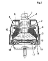
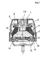
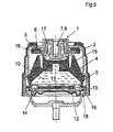
- FIGS. 1 to 6 in each case an embodiment of an assembly bearing according to the invention is shown, in which an inventive bearing core 1 is used.
- the bearing core 1 is in each case designed as MehrMechkem and comprises a sheath 2 made of a polymeric material and a stopper 5 made of a metallic material.
- the stopper 5 is formed in each case by a sheet metal part and in the FIGS. 1 and 6 partly, in the FIGS. 2 to 5 completely enclosed.
- the casing 2 is in any of the embodiments, a direct contact between the metallic stopper 5 and the spring body 4 made of elastomeric material; an undesirable in this case, material-related heat conduction from the stop 5 to the spring body 4 and into the interior of the assembly bearing is thereby avoided that the sheath 2 acts as a thermal insulation.
- the stopper 5 consists in the embodiments shown here of a metallic material which is thermally insulated from its surroundings by the sheath 2.
- the stopper 5 and the spring body 4 are enclosed by the cup-shaped stop housing 6, wherein the stopper housing 6 is flanged at its axially remote from the bearing core 1 end 18 to the corresponding end 19 of the support 3.
- the assembly bearing is designed as a hydraulic bearing and has a filled with damping fluid 10 Weg-11 and compensation chamber 12, which are separated by a partition wall 13 and liquid-conductively connected to each other through the damping channel 14.
- the hydraulic bearings are used in motor vehicles to support an internal combustion engine with respect to a chassis.
- FIG. 1 a first embodiment of an assembly bearing and a bearing core 1 is shown.
- the end face 17 of the stopper 5, which faces away axially from the working space 11, is flanged around a collar 20 of the fastening device 7
- the production of the bearing core 1 is such that the fastening device 7 and the stopper 5 are connected to a preassembled unit, wherein the preassemblable unit is then encapsulated with the polymeric material of the casing 2.
- FIG. 2 and FIG. 2a a second embodiment is shown in which the formed as a metallic deep drawn part stop 5 is completely enclosed by the casing 2.
- the fastening device 7 is encapsulated together with the stop 5 of the polymeric material of the casing 2.
- the fastening device 7 with respect to the sheath 2 by a mica disk 22 and a mica tube 23 is thermally insulated.
- FIG. 3 an embodiment is shown, similar to the embodiment of FIG. 2 , wherein the fastening element 7 is formed as a blind hole thread 8.
- FIG. 4 Is a further embodiment shown that differs from the embodiment FIG. 3 differs in that as a fastening element 7, a screw 9 is used.
- FIG. 5 an embodiment is shown, similar to the embodiment of FIG. 4 , The difference is that under the head of the screw 9, a disc 21 is arranged, via which the positive connection in the bearing core 1 is produced.
- FIG. 6 an embodiment is shown, with an intermediate ring 15 and an inner cable stop 16.
- an intermediate ring 15 can be combined with differently designed inner cable stops 16, so that, for example, fastening devices 7 in the form of a blind hole thread 8 accordingly FIG. 3 or in the form of a screw 9 accordingly FIG. 4 If necessary, they can be used.
Landscapes
- Engineering & Computer Science (AREA)
- General Engineering & Computer Science (AREA)
- Mechanical Engineering (AREA)
- Mounting Of Bearings Or Others (AREA)
- Support Of The Bearing (AREA)
- Springs (AREA)
- Sliding-Contact Bearings (AREA)
Priority Applications (1)
| Application Number | Priority Date | Filing Date | Title |
|---|---|---|---|
| PL10009075T PL2306044T3 (pl) | 2009-09-30 | 2010-09-01 | Podpora zespołu i rdzeń podpory dla podpory zespołu |
Applications Claiming Priority (1)
| Application Number | Priority Date | Filing Date | Title |
|---|---|---|---|
| DE102009043557.3A DE102009043557B4 (de) | 2009-09-30 | 2009-09-30 | Aggregatelager und ein Lagerkern dafür |
Publications (3)
| Publication Number | Publication Date |
|---|---|
| EP2306044A2 true EP2306044A2 (fr) | 2011-04-06 |
| EP2306044A3 EP2306044A3 (fr) | 2014-06-11 |
| EP2306044B1 EP2306044B1 (fr) | 2017-12-13 |
Family
ID=43413447
Family Applications (1)
| Application Number | Title | Priority Date | Filing Date |
|---|---|---|---|
| EP10009075.2A Active EP2306044B1 (fr) | 2009-09-30 | 2010-09-01 | Palier d'agrégat et noyau de palier correspondant |
Country Status (5)
| Country | Link |
|---|---|
| EP (1) | EP2306044B1 (fr) |
| CN (1) | CN201884544U (fr) |
| DE (1) | DE102009043557B4 (fr) |
| ES (1) | ES2660003T3 (fr) |
| PL (1) | PL2306044T3 (fr) |
Cited By (3)
| Publication number | Priority date | Publication date | Assignee | Title |
|---|---|---|---|---|
| WO2013159850A1 (fr) * | 2012-04-25 | 2013-10-31 | Carl Freudenberg Kg | Palier d'unité |
| EP2407684A3 (fr) * | 2010-07-14 | 2014-08-06 | Carl Freudenberg KG | Palier de groupe |
| US11085504B2 (en) * | 2019-05-28 | 2021-08-10 | Toyo Tire Corporation | Vibration isolator |
Families Citing this family (4)
| Publication number | Priority date | Publication date | Assignee | Title |
|---|---|---|---|---|
| JP5940877B2 (ja) * | 2012-04-27 | 2016-06-29 | 山下ゴム株式会社 | 液封防振装置 |
| CN104769311B (zh) * | 2013-09-10 | 2016-08-24 | 住友理工株式会社 | 流体封入式隔振装置 |
| WO2018062165A1 (fr) | 2016-09-27 | 2018-04-05 | 株式会社ブリヂストン | Dispositif d'amortissement de vibrations |
| JP6956658B2 (ja) * | 2018-03-14 | 2021-11-02 | 住友理工株式会社 | 流体封入式防振装置 |
Family Cites Families (17)
| Publication number | Priority date | Publication date | Assignee | Title |
|---|---|---|---|---|
| JPS6040143A (ja) * | 1983-08-12 | 1985-03-02 | Kuraray Co Ltd | 制振材用樹脂組成物 |
| JPH0781605B2 (ja) * | 1989-02-01 | 1995-09-06 | 東海ゴム工業株式会社 | 電気粘性流体使用装置 |
| JP3585584B2 (ja) * | 1995-06-19 | 2004-11-04 | 東洋ゴム工業株式会社 | エンジンマウント装置 |
| US6289571B1 (en) * | 1997-05-16 | 2001-09-18 | Yamashita Rubber Kabushiki Kaisha | Manufacturing process of antivibration device |
| DE19915798C2 (de) * | 1999-02-24 | 2001-06-28 | Freudenberg Carl Fa | Schaltbares, hydraulisch dämpfendes Lager |
| DE10064330A1 (de) * | 2000-12-21 | 2002-07-11 | Freudenberg Carl Kg | Hydrolager |
| JP4171182B2 (ja) * | 2001-03-02 | 2008-10-22 | 東洋ゴム工業株式会社 | エンジンマウント |
| JP3581924B2 (ja) * | 2001-03-09 | 2004-10-27 | 東洋ゴム工業株式会社 | 防振装置 |
| FR2828540B1 (fr) * | 2001-08-07 | 2003-10-31 | Hutchinson | Support antivibratoire hydraulique |
| DE10212692A1 (de) * | 2002-03-21 | 2003-10-02 | Freudenberg Carl Kg | Hydrolager |
| JP3841720B2 (ja) * | 2002-05-14 | 2006-11-01 | 東海ゴム工業株式会社 | ブラケット付き筒型マウント装置 |
| DE10262059B4 (de) * | 2002-12-04 | 2005-12-22 | Carl Freudenberg Kg | Tragarm |
| DE10310737B8 (de) * | 2003-03-10 | 2012-09-06 | Carl Freudenberg Kg | Hydraulisch dämpfendes Gummilager |
| DE102004006030B3 (de) * | 2004-02-06 | 2005-07-07 | Wegu Gmbh & Co. Kg | Schwingungstilger und Verfahren zu seiner Herstellung |
| US8376331B2 (en) * | 2008-03-06 | 2013-02-19 | The Pullman Company | External shear-hub isolator |
| JP5264272B2 (ja) * | 2008-04-30 | 2013-08-14 | 株式会社ブリヂストン | 防振装置 |
| EP2218935A1 (fr) * | 2009-02-17 | 2010-08-18 | Carl Freudenberg KG | Agencement de manchon |
-
2009
- 2009-09-30 DE DE102009043557.3A patent/DE102009043557B4/de active Active
-
2010
- 2010-09-01 ES ES10009075.2T patent/ES2660003T3/es active Active
- 2010-09-01 EP EP10009075.2A patent/EP2306044B1/fr active Active
- 2010-09-01 PL PL10009075T patent/PL2306044T3/pl unknown
- 2010-09-27 CN CN2010205896732U patent/CN201884544U/zh not_active Expired - Lifetime
Non-Patent Citations (1)
| Title |
|---|
| None |
Cited By (3)
| Publication number | Priority date | Publication date | Assignee | Title |
|---|---|---|---|---|
| EP2407684A3 (fr) * | 2010-07-14 | 2014-08-06 | Carl Freudenberg KG | Palier de groupe |
| WO2013159850A1 (fr) * | 2012-04-25 | 2013-10-31 | Carl Freudenberg Kg | Palier d'unité |
| US11085504B2 (en) * | 2019-05-28 | 2021-08-10 | Toyo Tire Corporation | Vibration isolator |
Also Published As
| Publication number | Publication date |
|---|---|
| EP2306044A3 (fr) | 2014-06-11 |
| ES2660003T3 (es) | 2018-03-20 |
| DE102009043557B4 (de) | 2017-10-19 |
| EP2306044B1 (fr) | 2017-12-13 |
| PL2306044T3 (pl) | 2018-05-30 |
| CN201884544U (zh) | 2011-06-29 |
| DE102009043557A1 (de) | 2011-05-05 |
Similar Documents
| Publication | Publication Date | Title |
|---|---|---|
| EP2306044B1 (fr) | Palier d'agrégat et noyau de palier correspondant | |
| DE69732700T2 (de) | Sphärisches elastomerlager | |
| DE102008040548A1 (de) | Hydraulisch dämpfendes Buchsenlager | |
| DE102010047464B4 (de) | Befestigungsanordnung | |
| DE102011102813A1 (de) | Kupplungszentralausrücker | |
| EP3504461B1 (fr) | Bloc de suspension | |
| DE102009005828A1 (de) | Nehmerzylinder für ein schwingungsgedämpftes hydraulisches Kraftübertragungssystem, insbesondere eine hydraulische Kupplungsbetätigung für Kraftfahrzeuge | |
| DE102017117142B4 (de) | Kühlmodullager und Baugruppe mit KFZ-Kühlmodul und Kühlmodullager | |
| EP2824362B2 (fr) | Amortisseur de vibrations de torsions | |
| EP3586028B1 (fr) | Palier élastique | |
| DE102017210867A1 (de) | Elektromotor | |
| DE112008000113B4 (de) | Kupplungsbetätigungsvorrichtung mit einer Anordnung zur Unterdrückung von Eigen-Resonanzen | |
| DE102007028041B4 (de) | Elastomerlager insbesondere für Fahrwerksbuchsen | |
| DE102019115232A1 (de) | Elektromechanisch unterstütztes Lenksystem | |
| DE102013221761A1 (de) | Gleitlagereinrichtung, elektrische Maschine | |
| DE10259801A1 (de) | Brennstoffeinspritzventil | |
| DE102017223382B3 (de) | Hydrolager | |
| EP2051353B1 (fr) | Unité d'entraînement | |
| DE102013101939A1 (de) | Antriebsanordnung für ein Aggregat eines Verbrennungsmotors | |
| DE102005053408A1 (de) | Betätigungseinrichtung | |
| DE102004035677B4 (de) | Stützlager mit mindestens zwei miteinander verbundenen Kammern | |
| EP2489898A2 (fr) | Palier et son procédé de fabrication | |
| DE102006005601A1 (de) | Fluiddynamisches Lagersystem | |
| EP2835548A1 (fr) | Agencement d'embrayage, notamment pour un embrayage à friction dans un système de débrayage d'un véhicule automobile | |
| DE102014009558A1 (de) | Halteanordnung zum schwingungsentkoppelten Befestigen zweier Bauteile |
Legal Events
| Date | Code | Title | Description |
|---|---|---|---|
| PUAI | Public reference made under article 153(3) epc to a published international application that has entered the european phase |
Free format text: ORIGINAL CODE: 0009012 |
|
| AK | Designated contracting states |
Kind code of ref document: A2 Designated state(s): AL AT BE BG CH CY CZ DE DK EE ES FI FR GB GR HR HU IE IS IT LI LT LU LV MC MK MT NL NO PL PT RO SE SI SK SM TR |
|
| AX | Request for extension of the european patent |
Extension state: BA ME RS |
|
| PUAL | Search report despatched |
Free format text: ORIGINAL CODE: 0009013 |
|
| AK | Designated contracting states |
Kind code of ref document: A3 Designated state(s): AL AT BE BG CH CY CZ DE DK EE ES FI FR GB GR HR HU IE IS IT LI LT LU LV MC MK MT NL NO PL PT RO SE SI SK SM TR |
|
| AX | Request for extension of the european patent |
Extension state: BA ME RS |
|
| RIC1 | Information provided on ipc code assigned before grant |
Ipc: F16F 13/10 20060101AFI20140508BHEP |
|
| 17P | Request for examination filed |
Effective date: 20141211 |
|
| RBV | Designated contracting states (corrected) |
Designated state(s): AL AT BE BG CH CY CZ DE DK EE ES FI FR GB GR HR HU IE IS IT LI LT LU LV MC MK MT NL NO PL PT RO SE SI SK SM TR |
|
| 17Q | First examination report despatched |
Effective date: 20160223 |
|
| RAP1 | Party data changed (applicant data changed or rights of an application transferred) |
Owner name: VIBRACOUSTIC GMBH |
|
| GRAP | Despatch of communication of intention to grant a patent |
Free format text: ORIGINAL CODE: EPIDOSNIGR1 |
|
| INTG | Intention to grant announced |
Effective date: 20170808 |
|
| GRAS | Grant fee paid |
Free format text: ORIGINAL CODE: EPIDOSNIGR3 |
|
| GRAA | (expected) grant |
Free format text: ORIGINAL CODE: 0009210 |
|
| AK | Designated contracting states |
Kind code of ref document: B1 Designated state(s): AL AT BE BG CH CY CZ DE DK EE ES FI FR GB GR HR HU IE IS IT LI LT LU LV MC MK MT NL NO PL PT RO SE SI SK SM TR |
|
| REG | Reference to a national code |
Ref country code: GB Ref legal event code: FG4D Free format text: NOT ENGLISH |
|
| REG | Reference to a national code |
Ref country code: AT Ref legal event code: REF Ref document number: 954716 Country of ref document: AT Kind code of ref document: T Effective date: 20171215 Ref country code: CH Ref legal event code: EP |
|
| REG | Reference to a national code |
Ref country code: IE Ref legal event code: FG4D Free format text: LANGUAGE OF EP DOCUMENT: GERMAN |
|
| REG | Reference to a national code |
Ref country code: DE Ref legal event code: R096 Ref document number: 502010014464 Country of ref document: DE |
|
| REG | Reference to a national code |
Ref country code: RO Ref legal event code: EPE |
|
| REG | Reference to a national code |
Ref country code: ES Ref legal event code: FG2A Ref document number: 2660003 Country of ref document: ES Kind code of ref document: T3 Effective date: 20180320 |
|
| REG | Reference to a national code |
Ref country code: NL Ref legal event code: MP Effective date: 20171213 |
|
| REG | Reference to a national code |
Ref country code: LT Ref legal event code: MG4D |
|
| PG25 | Lapsed in a contracting state [announced via postgrant information from national office to epo] |
Ref country code: SE Free format text: LAPSE BECAUSE OF FAILURE TO SUBMIT A TRANSLATION OF THE DESCRIPTION OR TO PAY THE FEE WITHIN THE PRESCRIBED TIME-LIMIT Effective date: 20171213 Ref country code: NO Free format text: LAPSE BECAUSE OF FAILURE TO SUBMIT A TRANSLATION OF THE DESCRIPTION OR TO PAY THE FEE WITHIN THE PRESCRIBED TIME-LIMIT Effective date: 20180313 Ref country code: LT Free format text: LAPSE BECAUSE OF FAILURE TO SUBMIT A TRANSLATION OF THE DESCRIPTION OR TO PAY THE FEE WITHIN THE PRESCRIBED TIME-LIMIT Effective date: 20171213 Ref country code: FI Free format text: LAPSE BECAUSE OF FAILURE TO SUBMIT A TRANSLATION OF THE DESCRIPTION OR TO PAY THE FEE WITHIN THE PRESCRIBED TIME-LIMIT Effective date: 20171213 |
|
| PG25 | Lapsed in a contracting state [announced via postgrant information from national office to epo] |
Ref country code: LV Free format text: LAPSE BECAUSE OF FAILURE TO SUBMIT A TRANSLATION OF THE DESCRIPTION OR TO PAY THE FEE WITHIN THE PRESCRIBED TIME-LIMIT Effective date: 20171213 Ref country code: BG Free format text: LAPSE BECAUSE OF FAILURE TO SUBMIT A TRANSLATION OF THE DESCRIPTION OR TO PAY THE FEE WITHIN THE PRESCRIBED TIME-LIMIT Effective date: 20180313 Ref country code: HR Free format text: LAPSE BECAUSE OF FAILURE TO SUBMIT A TRANSLATION OF THE DESCRIPTION OR TO PAY THE FEE WITHIN THE PRESCRIBED TIME-LIMIT Effective date: 20171213 Ref country code: GR Free format text: LAPSE BECAUSE OF FAILURE TO SUBMIT A TRANSLATION OF THE DESCRIPTION OR TO PAY THE FEE WITHIN THE PRESCRIBED TIME-LIMIT Effective date: 20180314 |
|
| PG25 | Lapsed in a contracting state [announced via postgrant information from national office to epo] |
Ref country code: NL Free format text: LAPSE BECAUSE OF FAILURE TO SUBMIT A TRANSLATION OF THE DESCRIPTION OR TO PAY THE FEE WITHIN THE PRESCRIBED TIME-LIMIT Effective date: 20171213 |
|
| REG | Reference to a national code |
Ref country code: SK Ref legal event code: T3 Ref document number: E 26743 Country of ref document: SK |
|
| PG25 | Lapsed in a contracting state [announced via postgrant information from national office to epo] |
Ref country code: CY Free format text: LAPSE BECAUSE OF FAILURE TO SUBMIT A TRANSLATION OF THE DESCRIPTION OR TO PAY THE FEE WITHIN THE PRESCRIBED TIME-LIMIT Effective date: 20171213 Ref country code: EE Free format text: LAPSE BECAUSE OF FAILURE TO SUBMIT A TRANSLATION OF THE DESCRIPTION OR TO PAY THE FEE WITHIN THE PRESCRIBED TIME-LIMIT Effective date: 20171213 |
|
| PG25 | Lapsed in a contracting state [announced via postgrant information from national office to epo] |
Ref country code: SM Free format text: LAPSE BECAUSE OF FAILURE TO SUBMIT A TRANSLATION OF THE DESCRIPTION OR TO PAY THE FEE WITHIN THE PRESCRIBED TIME-LIMIT Effective date: 20171213 Ref country code: IT Free format text: LAPSE BECAUSE OF FAILURE TO SUBMIT A TRANSLATION OF THE DESCRIPTION OR TO PAY THE FEE WITHIN THE PRESCRIBED TIME-LIMIT Effective date: 20171213 Ref country code: IS Free format text: LAPSE BECAUSE OF FAILURE TO SUBMIT A TRANSLATION OF THE DESCRIPTION OR TO PAY THE FEE WITHIN THE PRESCRIBED TIME-LIMIT Effective date: 20180413 |
|
| REG | Reference to a national code |
Ref country code: DE Ref legal event code: R097 Ref document number: 502010014464 Country of ref document: DE |
|
| REG | Reference to a national code |
Ref country code: FR Ref legal event code: PLFP Year of fee payment: 9 |
|
| PG25 | Lapsed in a contracting state [announced via postgrant information from national office to epo] |
Ref country code: MT Free format text: LAPSE BECAUSE OF FAILURE TO SUBMIT A TRANSLATION OF THE DESCRIPTION OR TO PAY THE FEE WITHIN THE PRESCRIBED TIME-LIMIT Effective date: 20171213 |
|
| PLBE | No opposition filed within time limit |
Free format text: ORIGINAL CODE: 0009261 |
|
| STAA | Information on the status of an ep patent application or granted ep patent |
Free format text: STATUS: NO OPPOSITION FILED WITHIN TIME LIMIT |
|
| 26N | No opposition filed |
Effective date: 20180914 |
|
| PG25 | Lapsed in a contracting state [announced via postgrant information from national office to epo] |
Ref country code: DK Free format text: LAPSE BECAUSE OF FAILURE TO SUBMIT A TRANSLATION OF THE DESCRIPTION OR TO PAY THE FEE WITHIN THE PRESCRIBED TIME-LIMIT Effective date: 20171213 |
|
| PGFP | Annual fee paid to national office [announced via postgrant information from national office to epo] |
Ref country code: DE Payment date: 20181031 Year of fee payment: 9 |
|
| PG25 | Lapsed in a contracting state [announced via postgrant information from national office to epo] |
Ref country code: SI Free format text: LAPSE BECAUSE OF FAILURE TO SUBMIT A TRANSLATION OF THE DESCRIPTION OR TO PAY THE FEE WITHIN THE PRESCRIBED TIME-LIMIT Effective date: 20171213 |
|
| PGFP | Annual fee paid to national office [announced via postgrant information from national office to epo] |
Ref country code: ES Payment date: 20181024 Year of fee payment: 9 |
|
| PG25 | Lapsed in a contracting state [announced via postgrant information from national office to epo] |
Ref country code: MC Free format text: LAPSE BECAUSE OF FAILURE TO SUBMIT A TRANSLATION OF THE DESCRIPTION OR TO PAY THE FEE WITHIN THE PRESCRIBED TIME-LIMIT Effective date: 20171213 |
|
| REG | Reference to a national code |
Ref country code: CH Ref legal event code: PL |
|
| REG | Reference to a national code |
Ref country code: BE Ref legal event code: MM Effective date: 20180930 |
|
| REG | Reference to a national code |
Ref country code: IE Ref legal event code: MM4A |
|
| PG25 | Lapsed in a contracting state [announced via postgrant information from national office to epo] |
Ref country code: LU Free format text: LAPSE BECAUSE OF NON-PAYMENT OF DUE FEES Effective date: 20180901 |
|
| PG25 | Lapsed in a contracting state [announced via postgrant information from national office to epo] |
Ref country code: IE Free format text: LAPSE BECAUSE OF NON-PAYMENT OF DUE FEES Effective date: 20180901 |
|
| PG25 | Lapsed in a contracting state [announced via postgrant information from national office to epo] |
Ref country code: BE Free format text: LAPSE BECAUSE OF NON-PAYMENT OF DUE FEES Effective date: 20180930 Ref country code: CH Free format text: LAPSE BECAUSE OF NON-PAYMENT OF DUE FEES Effective date: 20180930 Ref country code: LI Free format text: LAPSE BECAUSE OF NON-PAYMENT OF DUE FEES Effective date: 20180930 |
|
| PGFP | Annual fee paid to national office [announced via postgrant information from national office to epo] |
Ref country code: SK Payment date: 20190821 Year of fee payment: 10 Ref country code: RO Payment date: 20190820 Year of fee payment: 10 Ref country code: CZ Payment date: 20190823 Year of fee payment: 10 |
|
| REG | Reference to a national code |
Ref country code: AT Ref legal event code: MM01 Ref document number: 954716 Country of ref document: AT Kind code of ref document: T Effective date: 20180901 |
|
| PGFP | Annual fee paid to national office [announced via postgrant information from national office to epo] |
Ref country code: PL Payment date: 20190826 Year of fee payment: 10 |
|
| PGFP | Annual fee paid to national office [announced via postgrant information from national office to epo] |
Ref country code: GB Payment date: 20190924 Year of fee payment: 10 |
|
| PG25 | Lapsed in a contracting state [announced via postgrant information from national office to epo] |
Ref country code: AT Free format text: LAPSE BECAUSE OF NON-PAYMENT OF DUE FEES Effective date: 20180901 |
|
| REG | Reference to a national code |
Ref country code: DE Ref legal event code: R119 Ref document number: 502010014464 Country of ref document: DE |
|
| REG | Reference to a national code |
Ref country code: DE Ref legal event code: R082 Ref document number: 502010014464 Country of ref document: DE Representative=s name: PATENTANWAELTE OLBRICHT, BUCHHOLD, KEULERTZ PA, DE |
|
| PG25 | Lapsed in a contracting state [announced via postgrant information from national office to epo] |
Ref country code: HU Free format text: LAPSE BECAUSE OF FAILURE TO SUBMIT A TRANSLATION OF THE DESCRIPTION OR TO PAY THE FEE WITHIN THE PRESCRIBED TIME-LIMIT; INVALID AB INITIO Effective date: 20100901 Ref country code: PT Free format text: LAPSE BECAUSE OF FAILURE TO SUBMIT A TRANSLATION OF THE DESCRIPTION OR TO PAY THE FEE WITHIN THE PRESCRIBED TIME-LIMIT Effective date: 20171213 |
|
| PG25 | Lapsed in a contracting state [announced via postgrant information from national office to epo] |
Ref country code: MK Free format text: LAPSE BECAUSE OF NON-PAYMENT OF DUE FEES Effective date: 20171213 |
|
| PG25 | Lapsed in a contracting state [announced via postgrant information from national office to epo] |
Ref country code: DE Free format text: LAPSE BECAUSE OF NON-PAYMENT OF DUE FEES Effective date: 20200401 Ref country code: AL Free format text: LAPSE BECAUSE OF FAILURE TO SUBMIT A TRANSLATION OF THE DESCRIPTION OR TO PAY THE FEE WITHIN THE PRESCRIBED TIME-LIMIT Effective date: 20171213 |
|
| REG | Reference to a national code |
Ref country code: ES Ref legal event code: FD2A Effective date: 20210127 |
|
| PG25 | Lapsed in a contracting state [announced via postgrant information from national office to epo] |
Ref country code: CZ Free format text: LAPSE BECAUSE OF NON-PAYMENT OF DUE FEES Effective date: 20200901 Ref country code: RO Free format text: LAPSE BECAUSE OF NON-PAYMENT OF DUE FEES Effective date: 20200901 |
|
| GBPC | Gb: european patent ceased through non-payment of renewal fee |
Effective date: 20200901 |
|
| REG | Reference to a national code |
Ref country code: SK Ref legal event code: MM4A Ref document number: E 26743 Country of ref document: SK Effective date: 20200901 |
|
| PG25 | Lapsed in a contracting state [announced via postgrant information from national office to epo] |
Ref country code: ES Free format text: LAPSE BECAUSE OF NON-PAYMENT OF DUE FEES Effective date: 20190902 |
|
| PG25 | Lapsed in a contracting state [announced via postgrant information from national office to epo] |
Ref country code: SK Free format text: LAPSE BECAUSE OF NON-PAYMENT OF DUE FEES Effective date: 20200901 |
|
| PG25 | Lapsed in a contracting state [announced via postgrant information from national office to epo] |
Ref country code: GB Free format text: LAPSE BECAUSE OF NON-PAYMENT OF DUE FEES Effective date: 20200901 |
|
| PG25 | Lapsed in a contracting state [announced via postgrant information from national office to epo] |
Ref country code: TR Free format text: LAPSE BECAUSE OF NON-PAYMENT OF DUE FEES Effective date: 20190901 |
|
| PG25 | Lapsed in a contracting state [announced via postgrant information from national office to epo] |
Ref country code: PL Free format text: LAPSE BECAUSE OF NON-PAYMENT OF DUE FEES Effective date: 20200901 |
|
| PGFP | Annual fee paid to national office [announced via postgrant information from national office to epo] |
Ref country code: FR Payment date: 20250919 Year of fee payment: 16 |