EP2306086A2 - Barreau de grille - Google Patents
Barreau de grille Download PDFInfo
- Publication number
- EP2306086A2 EP2306086A2 EP10008873A EP10008873A EP2306086A2 EP 2306086 A2 EP2306086 A2 EP 2306086A2 EP 10008873 A EP10008873 A EP 10008873A EP 10008873 A EP10008873 A EP 10008873A EP 2306086 A2 EP2306086 A2 EP 2306086A2
- Authority
- EP
- European Patent Office
- Prior art keywords
- grate bar
- grate
- bar according
- upper side
- wear plate
- Prior art date
- Legal status (The legal status is an assumption and is not a legal conclusion. Google has not performed a legal analysis and makes no representation as to the accuracy of the status listed.)
- Granted
Links
Images

Classifications
-
- F—MECHANICAL ENGINEERING; LIGHTING; HEATING; WEAPONS; BLASTING
- F23—COMBUSTION APPARATUS; COMBUSTION PROCESSES
- F23H—GRATES; CLEANING OR RAKING GRATES
- F23H3/00—Grates with hollow bars
- F23H3/02—Grates with hollow bars internally cooled
Definitions
- the present invention relates to a grate bar for placement in a grate of an incinerator.
- combustion grate An important component of a combustion plant, such as a waste incineration plant for the thermal utilization of waste, is a combustion grate.
- a combustion grate On such a combustion grate arranged horizontally or inclined in an incinerator, the combustible material travels from a first end to a second end, the first end being the feedstock for the kiln and the second end typically being referred to as a burnout grate on which the thermal conversion of the kiln concludes.
- Combustion grates are nowadays usually constructed from a plurality of individual grate bars, which are joined together to form a corresponding combustion grate. This structure allows for easy replacement of individual grate bars in case of damage to individual areas of the grate.
- the grate bars are usually set in rows next to each other, wherein the rows are arranged one above the other like a step, so that the rows partially overlap.
- the individual rows are mutually displaceable to allow a transport of the fuel by a displacement of the overlapping grate bar rows against each other.
- the grate bars used in such incinerators and of these Gratings formed must on the one hand have sufficient mechanical stability in order to be able to absorb and transport the firing material, and on the other hand they must have suitable high-temperature resistance in order to be able to withstand the temperatures occurring during the thermal conversion of the firing material.
- the grate bars or gratings are flown from an underside with an air flow and have outlet openings, through which the incoming combustion air can pass into the kiln.
- Such grates or grate bars are for example from the DE 20111804 U1 known.
- the European patent specification EP 1 612 483 B1 discloses a corresponding grate bar for use in incinerators, which is flown from an underside with an air flow, wherein the grate bars shown here have air ducts over which the stream of air flowed from below is passed through the grate so that it lies on the lying in the feed direction longitudinal side of the Roststabes exit and there flows into the kiln.
- a problem with the use of rust or grate bars in incinerators is the high-temperature corrosion occurring there.
- High-temperature corrosion is a phenomenon similar to wet corrosion, but in this case corrosion is not caused by aqueous media, but rather by reactions of the material with the kiln or gaseous compounds produced during combustion.
- halide-containing salts under the conditions prevailing in incinerators lead to the formation of volatile halides which attack the protective oxide layer formed on the material and thus lead to corrosion of the materials.
- a grate bar for arrangement in a grate of a combustion plant, with an upper side, an end face, a rear longitudinal face and a lower face, wherein the upper face and end face merge into one another via an arc section, which is characterized in that at least below the arc section a wear plate is arranged.
- the inventively provided wear plate is preferably arranged at a distance from the arc section on the inside of the grate bar.
- a grate bar according to the invention may have on its upper side an outlet opening for gaseous media directed against the lower side, such as, for example, combustion air. Through this opening, the combustion air passes from the area below the grate bar in the firing rod located on the grate bar. As a result, combustion air is passed into the kiln in such a way that a sufficient supply of the combustion process with combustion air is ensured.
- gaseous media directed against the lower side
- the inventively provided wear plate may be attached to a central rib of the grate bar or be formed on this.
- this is integrally formed, so that the wear plate is integrally formed on a central rib of the grate bar.
- this can be cast, for example, from a suitable material.
- the above-mentioned center rib may comprise support webs or cooling webs in a grate bar according to the invention, via which the center rib is supported relative to the upper side of the grate bar.
- the support webs or cooling webs can fulfill air-conducting functions and ensure guidance of the air flow directed from below against the grate bar to the outlet opening arranged at the top of the grate bar.
- a grate bar according to the invention can have recesses, in particular in the region of the center rib, via which a plurality of grate bars can be connected to one another.
- connecting means for example connecting webs are suitable, which are insertable into the recesses.
- a grate bar according to the invention can have a support section with which it can be placed on a holding bar.
- the support rod serves at the same time as a pivot bearing, around which a rotation of the grate bar is made possible when moving superposed, individual grate sections forming grate bars.
- this has a support section both in the front region of the grate bar and in the rear region. This makes it possible to turn the grate bar in the case of too large corrosion phenomena in the region of the front arc section and so to make the rear section of the grate bar to a front section. This doubles the service life of the individual grate bar.
- this is designed mirror-symmetrically for this purpose to a transversely to the longitudinal extent of the grate bar mirror plane.
- the wear plate is formed from a different material from the rest of the material of the grate bar.
- the material of the wear plate on a higher high temperature corrosion resistance as the material of the rest of the grate bar.
- the wear plate is attached to the grate bar by suitable fastening means such as welding, screwing and the like or via a press fit.
- the grate bar in a central rib having a shape corresponding to the wear plate recess into which the wear plate is inserted and clamped there in a suitable manner.
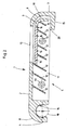
- Fig. 1 shows a grate bar 1 according to the invention with a top 2, an end face 3, a rear longitudinal surface 4 and a bottom 5.
- the grate bar 1 according to the invention may have a central rib 11 which is supported by support webs or cooling webs 12 with respect to the upper side 2.
- the center rib 11 may have recesses 13, in which connecting means, such as Connecting rods are insertable, whereby a plurality of grate bars 1 according to the invention can be combined to form a grate.
- connecting means such as Connecting rods
- a wear plate 7 is arranged at the center rib 11.
- the wear plate 7 is preferably spaced from the arc section 6 and may have support webs 17, via which it is supported relative to the center rib 11.
- the grate bar 1 according to the invention has a support part 14 with which it rests on a support rod 18.
- the grate bar 1 according to the invention can be arranged in a grid overlapping to adjacent grate bars, wherein it rests with a foot 15 on the top of a grate bar adjacent to its end face 3.
- Fig. 2 shows an embodiment of a grate bar 1 according to the invention, also with a top 2, an end face 3, a rear longitudinal face 4 and a bottom 5.
- Fig. 2 shown grate bar corresponds essentially to the structure of the grate bar, as in Fig. 1 is shown.
- the in Fig. 2 However, shown grate bar has below the outlet opening 10 and adjacent to the wear plate 7 has a passage 16, via which can flow from the bottom 5 of combustion air flowed into a transfer port 19 before it exits through the outlet opening on the top of the grate bar 1 according to the invention and in the Brenngut arrives.
- the overflow channel 19 begins in the region of the foot 15 and terminates in the present embodiment in the region of the end of the arranged on the upper side 2 outlet opening 10.
- the brought up from the bottom 5 combustion air can also get into the space 20 above the foot 15 and from there via the overflow channel 19 to the outlet opening 10.
- the arc section 6 can be cooled by means of the air flow prevailing in the overflow channel 19, whereby the occurring at the surface of the arc section 6 high-temperature corrosion can be reduced. This leads to a further extension of the service life of the grate bar 1 according to the invention.
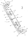
- Fig. 3 shows an embodiment of a grate bar 1 according to the invention, which is designed for double-sided support on a support rod.
- the in Fig. 3 shown grate bar also has a top 2, a bottom 5, an end face 3 and a rear longitudinal surface 4, wherein end face 3 and rear longitudinal surface 4 are mirror-symmetrical to each other.
- wear plates 7, 9 are arranged, which to the above lying arc sections 6, 8 are spaced.
- the wear plates 7, 9 are integrally formed on a central rib 11.
- the center rib 11 also has recesses 13, in which connecting means are insertable to assemble a plurality of grate bars 1 to a grid.
- the center rib 11 has support webs or cooling webs 12, via which it is supported relative to the upper side 2.
- an outlet opening 10 is arranged on the upper side 2, via which escape from the underside 5 of incoming combustion air and can get into the lying on top of the kiln.
- combustion rods 1 according to the invention are arranged relative to one another in such a way that the support part 21 comes to rest on a support rod, while the foot 15 comes to rest on the upper side of a grate rod adjacent to the end surface 3.
- the wear plate 7 can now first ensure that the functionality of the grate bar 1 is maintained. In the course of the grate bar 1 can be reversed, so that the corrosively attacked arc section 6 comes to rest in the rear region of the grate bar 1 and this is placed on the support section 14 on a support rod. By then adjacent to corrosive attacked arc section grate bar the attacked area of the grate bar 1 is shielded and is not exposed to any further high-temperature corrosion. As a result, the service life of the grate bar according to the invention can be further increased.
Landscapes
- Engineering & Computer Science (AREA)
- Chemical & Material Sciences (AREA)
- Combustion & Propulsion (AREA)
- Mechanical Engineering (AREA)
- General Engineering & Computer Science (AREA)
- Incineration Of Waste (AREA)
- Air-Flow Control Members (AREA)
Priority Applications (1)
| Application Number | Priority Date | Filing Date | Title |
|---|---|---|---|
| PL10008873T PL2306086T3 (pl) | 2009-09-23 | 2010-08-26 | Rusztowina |
Applications Claiming Priority (1)
| Application Number | Priority Date | Filing Date | Title |
|---|---|---|---|
| DE200910042722 DE102009042722A1 (de) | 2009-09-23 | 2009-09-23 | Roststab |
Publications (3)
| Publication Number | Publication Date |
|---|---|
| EP2306086A2 true EP2306086A2 (fr) | 2011-04-06 |
| EP2306086A3 EP2306086A3 (fr) | 2013-02-20 |
| EP2306086B1 EP2306086B1 (fr) | 2017-12-27 |
Family
ID=42831582
Family Applications (1)
| Application Number | Title | Priority Date | Filing Date |
|---|---|---|---|
| EP10008873.1A Active EP2306086B1 (fr) | 2009-09-23 | 2010-08-26 | Barreau de grille |
Country Status (7)
| Country | Link |
|---|---|
| EP (1) | EP2306086B1 (fr) |
| DE (1) | DE102009042722A1 (fr) |
| DK (1) | DK2306086T3 (fr) |
| PL (1) | PL2306086T3 (fr) |
| PT (1) | PT2306086T (fr) |
| RU (1) | RU2010139008A (fr) |
| TR (1) | TR201802367T4 (fr) |
Cited By (4)
| Publication number | Priority date | Publication date | Assignee | Title |
|---|---|---|---|---|
| EP2511609A2 (fr) | 2011-04-15 | 2012-10-17 | WVT Breiding GmbH | Barreau de grille modulaire, élément de recouvrement, élément de bande combustible et élément de base associé ainsi que la grille d'avance d'une installation de combustion |
| DE202011005341U1 (de) | 2011-04-15 | 2014-05-20 | Wvt Breiding Gmbh | Modularer Roststab, Auflageelement, Brennbahnelement und Fußelement dafür sowie Vorschubrost einer Verbrennungsanlage |
| DE102014004660A1 (de) | 2014-02-10 | 2015-08-13 | Joachim Kümmel | Verfahren zur Verbrennung von Abfall und Biomassen auf einem luftgekühlten Rost sowie Vorrichtung zur Durchführung des Verfahrens |
| DE102014008858A1 (de) | 2014-06-16 | 2015-12-17 | Joachim Kümmel | Verfahren zur Verbrennung von Abfall und Biomassen auf einem Flossenwand-Stufenrost sowie Vorrichtung zur Durchführung des Verfahrens |
Citations (2)
| Publication number | Priority date | Publication date | Assignee | Title |
|---|---|---|---|---|
| DE20111804U1 (de) | 2001-07-16 | 2001-09-27 | WVT Breiding GmbH, 58239 Schwerte | Rost und Roststäbe |
| EP1612483B1 (fr) | 2004-07-03 | 2008-07-23 | AE & E Lentjes GmbH | Elément de grille, grille de combustion associée et installation d'incinération de matière résiduelle |
Family Cites Families (4)
| Publication number | Priority date | Publication date | Assignee | Title |
|---|---|---|---|---|
| CH652476A5 (de) * | 1983-05-20 | 1985-11-15 | Theodor Koch | Roststab. |
| DE3570119D1 (en) * | 1984-05-21 | 1989-06-15 | Theodor Koch | Furnace, especially for the combustion of refuse, coal, wood and industrial waste |
| JPH11504700A (ja) * | 1995-03-23 | 1999-04-27 | コッホ,テオドール | 燃焼炉の火格子 |
| DE19528310A1 (de) * | 1995-08-02 | 1997-02-06 | Abb Management Ag | Rost für eine Feuerungsanlage |
-
2009
- 2009-09-23 DE DE200910042722 patent/DE102009042722A1/de not_active Ceased
-
2010
- 2010-08-26 PL PL10008873T patent/PL2306086T3/pl unknown
- 2010-08-26 DK DK10008873.1T patent/DK2306086T3/en active
- 2010-08-26 PT PT100088731T patent/PT2306086T/pt unknown
- 2010-08-26 EP EP10008873.1A patent/EP2306086B1/fr active Active
- 2010-08-26 TR TR2018/02367T patent/TR201802367T4/tr unknown
- 2010-09-23 RU RU2010139008/06A patent/RU2010139008A/ru not_active Application Discontinuation
Patent Citations (2)
| Publication number | Priority date | Publication date | Assignee | Title |
|---|---|---|---|---|
| DE20111804U1 (de) | 2001-07-16 | 2001-09-27 | WVT Breiding GmbH, 58239 Schwerte | Rost und Roststäbe |
| EP1612483B1 (fr) | 2004-07-03 | 2008-07-23 | AE & E Lentjes GmbH | Elément de grille, grille de combustion associée et installation d'incinération de matière résiduelle |
Cited By (5)
| Publication number | Priority date | Publication date | Assignee | Title |
|---|---|---|---|---|
| EP2511609A2 (fr) | 2011-04-15 | 2012-10-17 | WVT Breiding GmbH | Barreau de grille modulaire, élément de recouvrement, élément de bande combustible et élément de base associé ainsi que la grille d'avance d'une installation de combustion |
| DE102011100369A1 (de) | 2011-04-15 | 2012-10-18 | Wvt Breiding Gmbh | Modularer Roststab, Auflageelement, Brennbahnelement und Fußelement dafür sowie Vorschubrost einer Verbrennungsanlage |
| DE202011005341U1 (de) | 2011-04-15 | 2014-05-20 | Wvt Breiding Gmbh | Modularer Roststab, Auflageelement, Brennbahnelement und Fußelement dafür sowie Vorschubrost einer Verbrennungsanlage |
| DE102014004660A1 (de) | 2014-02-10 | 2015-08-13 | Joachim Kümmel | Verfahren zur Verbrennung von Abfall und Biomassen auf einem luftgekühlten Rost sowie Vorrichtung zur Durchführung des Verfahrens |
| DE102014008858A1 (de) | 2014-06-16 | 2015-12-17 | Joachim Kümmel | Verfahren zur Verbrennung von Abfall und Biomassen auf einem Flossenwand-Stufenrost sowie Vorrichtung zur Durchführung des Verfahrens |
Also Published As
| Publication number | Publication date |
|---|---|
| DE102009042722A1 (de) | 2011-03-24 |
| PL2306086T3 (pl) | 2018-06-29 |
| DK2306086T3 (en) | 2018-04-09 |
| TR201802367T4 (tr) | 2018-03-21 |
| PT2306086T (pt) | 2018-03-06 |
| RU2010139008A (ru) | 2012-03-27 |
| EP2306086B1 (fr) | 2017-12-27 |
| EP2306086A3 (fr) | 2013-02-20 |
Similar Documents
| Publication | Publication Date | Title |
|---|---|---|
| EP0499912B1 (fr) | Barreau de grille et grille pour installations de combustion | |
| EP1617143B1 (fr) | Barreau de grille, grille et incinerateur équipés dudit barreau | |
| EP0165432B1 (fr) | Four, notamment pour la combustion des ordures, du charbon, du bois et des déchets industriels | |
| EP2306086B1 (fr) | Barreau de grille | |
| EP2487414B1 (fr) | Barreau de grille | |
| EP2511609B1 (fr) | Barreau de grille modulaire, élément de recouvrement et élément de base associé ainsi que la grille d'avance d'une installation de combustion | |
| DE3804815A1 (de) | Rostanordnung, insbesondere fuer stufenschwenkroste | |
| DE3407441C2 (de) | Wirbelschicht-Verbrennungsofen | |
| EP0825383B1 (fr) | Plaque de grille | |
| EP2184540B1 (fr) | Bloc de grille à refroidissement par air | |
| EP1612483B1 (fr) | Elément de grille, grille de combustion associée et installation d'incinération de matière résiduelle | |
| DE4335085C1 (de) | Feuerrost-Befestigungskonstruktion | |
| DE2000631C3 (de) | Wärmetauscher mit kontinuirlicher Schüttgutförderung | |
| DE3813441C2 (fr) | ||
| DE10148686C1 (de) | Brennvorrichtung | |
| DE102019129171B4 (de) | Roststab für Stufenrost | |
| DE102020203289A1 (de) | Kühler zum Kühlen von Schüttgut, insbesondere Zementklinker | |
| EP2362144A1 (fr) | Barreau de grille | |
| BE1028148B1 (de) | Kühler zum Kühlen von Schüttgut, insbesondere Zementklinker | |
| EP3348903B1 (fr) | Bloc de grillage | |
| EP4118390B1 (fr) | Refroidisseur pour refroidir un matériau en vrac, en particulier du clinker de ciment | |
| DE19860553C2 (de) | Flüssigkeitsgekühlter Verbrennungsrost | |
| DE29501162U1 (de) | Verbrennungsrost zum Verbrennen von festen Brennstoffen wie Müll, insbesondere zur Verbesserung des Ausbrandes | |
| DE102006024632A1 (de) | Walzenrost | |
| DE29809506U1 (de) | Lagerungselement für eine Rutschplatte |
Legal Events
| Date | Code | Title | Description |
|---|---|---|---|
| PUAI | Public reference made under article 153(3) epc to a published international application that has entered the european phase |
Free format text: ORIGINAL CODE: 0009012 |
|
| AK | Designated contracting states |
Kind code of ref document: A2 Designated state(s): AL AT BE BG CH CY CZ DE DK EE ES FI FR GB GR HR HU IE IS IT LI LT LU LV MC MK MT NL NO PL PT RO SE SI SK SM TR |
|
| AX | Request for extension of the european patent |
Extension state: BA ME RS |
|
| RAP1 | Party data changed (applicant data changed or rights of an application transferred) |
Owner name: XERVON ENERGY GMBH |
|
| RAP1 | Party data changed (applicant data changed or rights of an application transferred) |
Owner name: HITACHI POWER EUROPE SERVICE GMBH |
|
| PUAL | Search report despatched |
Free format text: ORIGINAL CODE: 0009013 |
|
| AK | Designated contracting states |
Kind code of ref document: A3 Designated state(s): AL AT BE BG CH CY CZ DE DK EE ES FI FR GB GR HR HU IE IS IT LI LT LU LV MC MK MT NL NO PL PT RO SE SI SK SM TR |
|
| AX | Request for extension of the european patent |
Extension state: BA ME RS |
|
| RIC1 | Information provided on ipc code assigned before grant |
Ipc: F23H 3/02 20060101AFI20130111BHEP |
|
| 17P | Request for examination filed |
Effective date: 20130618 |
|
| RAP1 | Party data changed (applicant data changed or rights of an application transferred) |
Owner name: MH POWER SYSTEMS EUROPE SERVICE GMBH |
|
| 17Q | First examination report despatched |
Effective date: 20160621 |
|
| GRAP | Despatch of communication of intention to grant a patent |
Free format text: ORIGINAL CODE: EPIDOSNIGR1 |
|
| INTG | Intention to grant announced |
Effective date: 20170725 |
|
| GRAA | (expected) grant |
Free format text: ORIGINAL CODE: 0009210 |
|
| GRAS | Grant fee paid |
Free format text: ORIGINAL CODE: EPIDOSNIGR3 |
|
| AK | Designated contracting states |
Kind code of ref document: B1 Designated state(s): AL AT BE BG CH CY CZ DE DK EE ES FI FR GB GR HR HU IE IS IT LI LT LU LV MC MK MT NL NO PL PT RO SE SI SK SM TR |
|
| RAP1 | Party data changed (applicant data changed or rights of an application transferred) |
Owner name: MHPS EUROPE GMBH |
|
| REG | Reference to a national code |
Ref country code: GB Ref legal event code: FG4D Free format text: NOT ENGLISH |
|
| REG | Reference to a national code |
Ref country code: CH Ref legal event code: EP |
|
| REG | Reference to a national code |
Ref country code: AT Ref legal event code: REF Ref document number: 958615 Country of ref document: AT Kind code of ref document: T Effective date: 20180115 |
|
| REG | Reference to a national code |
Ref country code: IE Ref legal event code: FG4D Free format text: LANGUAGE OF EP DOCUMENT: GERMAN |
|
| REG | Reference to a national code |
Ref country code: DE Ref legal event code: R096 Ref document number: 502010014500 Country of ref document: DE |
|
| REG | Reference to a national code |
Ref country code: PT Ref legal event code: SC4A Ref document number: 2306086 Country of ref document: PT Date of ref document: 20180306 Kind code of ref document: T Free format text: AVAILABILITY OF NATIONAL TRANSLATION Effective date: 20180227 |
|
| REG | Reference to a national code |
Ref country code: NL Ref legal event code: FP |
|
| REG | Reference to a national code |
Ref country code: DK Ref legal event code: T3 Effective date: 20180405 |
|
| REG | Reference to a national code |
Ref country code: SE Ref legal event code: TRGR |
|
| PG25 | Lapsed in a contracting state [announced via postgrant information from national office to epo] |
Ref country code: NO Free format text: LAPSE BECAUSE OF FAILURE TO SUBMIT A TRANSLATION OF THE DESCRIPTION OR TO PAY THE FEE WITHIN THE PRESCRIBED TIME-LIMIT Effective date: 20180327 Ref country code: FI Free format text: LAPSE BECAUSE OF FAILURE TO SUBMIT A TRANSLATION OF THE DESCRIPTION OR TO PAY THE FEE WITHIN THE PRESCRIBED TIME-LIMIT Effective date: 20171227 Ref country code: LT Free format text: LAPSE BECAUSE OF FAILURE TO SUBMIT A TRANSLATION OF THE DESCRIPTION OR TO PAY THE FEE WITHIN THE PRESCRIBED TIME-LIMIT Effective date: 20171227 |
|
| REG | Reference to a national code |
Ref country code: LT Ref legal event code: MG4D |
|
| PG25 | Lapsed in a contracting state [announced via postgrant information from national office to epo] |
Ref country code: LV Free format text: LAPSE BECAUSE OF FAILURE TO SUBMIT A TRANSLATION OF THE DESCRIPTION OR TO PAY THE FEE WITHIN THE PRESCRIBED TIME-LIMIT Effective date: 20171227 Ref country code: HR Free format text: LAPSE BECAUSE OF FAILURE TO SUBMIT A TRANSLATION OF THE DESCRIPTION OR TO PAY THE FEE WITHIN THE PRESCRIBED TIME-LIMIT Effective date: 20171227 Ref country code: GR Free format text: LAPSE BECAUSE OF FAILURE TO SUBMIT A TRANSLATION OF THE DESCRIPTION OR TO PAY THE FEE WITHIN THE PRESCRIBED TIME-LIMIT Effective date: 20180328 Ref country code: BG Free format text: LAPSE BECAUSE OF FAILURE TO SUBMIT A TRANSLATION OF THE DESCRIPTION OR TO PAY THE FEE WITHIN THE PRESCRIBED TIME-LIMIT Effective date: 20180327 |
|
| PG25 | Lapsed in a contracting state [announced via postgrant information from national office to epo] |
Ref country code: SK Free format text: LAPSE BECAUSE OF FAILURE TO SUBMIT A TRANSLATION OF THE DESCRIPTION OR TO PAY THE FEE WITHIN THE PRESCRIBED TIME-LIMIT Effective date: 20171227 Ref country code: CY Free format text: LAPSE BECAUSE OF FAILURE TO SUBMIT A TRANSLATION OF THE DESCRIPTION OR TO PAY THE FEE WITHIN THE PRESCRIBED TIME-LIMIT Effective date: 20171227 Ref country code: ES Free format text: LAPSE BECAUSE OF FAILURE TO SUBMIT A TRANSLATION OF THE DESCRIPTION OR TO PAY THE FEE WITHIN THE PRESCRIBED TIME-LIMIT Effective date: 20171227 Ref country code: EE Free format text: LAPSE BECAUSE OF FAILURE TO SUBMIT A TRANSLATION OF THE DESCRIPTION OR TO PAY THE FEE WITHIN THE PRESCRIBED TIME-LIMIT Effective date: 20171227 |
|
| REG | Reference to a national code |
Ref country code: FR Ref legal event code: PLFP Year of fee payment: 9 |
|
| PG25 | Lapsed in a contracting state [announced via postgrant information from national office to epo] |
Ref country code: RO Free format text: LAPSE BECAUSE OF FAILURE TO SUBMIT A TRANSLATION OF THE DESCRIPTION OR TO PAY THE FEE WITHIN THE PRESCRIBED TIME-LIMIT Effective date: 20171227 Ref country code: IS Free format text: LAPSE BECAUSE OF FAILURE TO SUBMIT A TRANSLATION OF THE DESCRIPTION OR TO PAY THE FEE WITHIN THE PRESCRIBED TIME-LIMIT Effective date: 20180427 Ref country code: SM Free format text: LAPSE BECAUSE OF FAILURE TO SUBMIT A TRANSLATION OF THE DESCRIPTION OR TO PAY THE FEE WITHIN THE PRESCRIBED TIME-LIMIT Effective date: 20171227 |
|
| PG25 | Lapsed in a contracting state [announced via postgrant information from national office to epo] |
Ref country code: MT Free format text: LAPSE BECAUSE OF FAILURE TO SUBMIT A TRANSLATION OF THE DESCRIPTION OR TO PAY THE FEE WITHIN THE PRESCRIBED TIME-LIMIT Effective date: 20171227 |
|
| REG | Reference to a national code |
Ref country code: DE Ref legal event code: R097 Ref document number: 502010014500 Country of ref document: DE |
|
| PGFP | Annual fee paid to national office [announced via postgrant information from national office to epo] |
Ref country code: GB Payment date: 20180927 Year of fee payment: 16 |
|
| PLBE | No opposition filed within time limit |
Free format text: ORIGINAL CODE: 0009261 |
|
| STAA | Information on the status of an ep patent application or granted ep patent |
Free format text: STATUS: NO OPPOSITION FILED WITHIN TIME LIMIT |
|
| PGFP | Annual fee paid to national office [announced via postgrant information from national office to epo] |
Ref country code: BE Payment date: 20180822 Year of fee payment: 9 Ref country code: TR Payment date: 20180814 Year of fee payment: 9 |
|
| 26N | No opposition filed |
Effective date: 20180928 |
|
| PGFP | Annual fee paid to national office [announced via postgrant information from national office to epo] |
Ref country code: PT Payment date: 20180821 Year of fee payment: 9 |
|
| PG25 | Lapsed in a contracting state [announced via postgrant information from national office to epo] |
Ref country code: SI Free format text: LAPSE BECAUSE OF FAILURE TO SUBMIT A TRANSLATION OF THE DESCRIPTION OR TO PAY THE FEE WITHIN THE PRESCRIBED TIME-LIMIT Effective date: 20171227 |
|
| PG25 | Lapsed in a contracting state [announced via postgrant information from national office to epo] |
Ref country code: MC Free format text: LAPSE BECAUSE OF FAILURE TO SUBMIT A TRANSLATION OF THE DESCRIPTION OR TO PAY THE FEE WITHIN THE PRESCRIBED TIME-LIMIT Effective date: 20171227 |
|
| PG25 | Lapsed in a contracting state [announced via postgrant information from national office to epo] |
Ref country code: LU Free format text: LAPSE BECAUSE OF NON-PAYMENT OF DUE FEES Effective date: 20180826 |
|
| REG | Reference to a national code |
Ref country code: DK Ref legal event code: EBP Effective date: 20190831 |
|
| PG25 | Lapsed in a contracting state [announced via postgrant information from national office to epo] |
Ref country code: PT Free format text: LAPSE BECAUSE OF NON-PAYMENT OF DUE FEES Effective date: 20200226 |
|
| PG25 | Lapsed in a contracting state [announced via postgrant information from national office to epo] |
Ref country code: HU Free format text: LAPSE BECAUSE OF FAILURE TO SUBMIT A TRANSLATION OF THE DESCRIPTION OR TO PAY THE FEE WITHIN THE PRESCRIBED TIME-LIMIT; INVALID AB INITIO Effective date: 20100826 Ref country code: CZ Free format text: LAPSE BECAUSE OF NON-PAYMENT OF DUE FEES Effective date: 20190826 |
|
| REG | Reference to a national code |
Ref country code: BE Ref legal event code: MM Effective date: 20190831 |
|
| PG25 | Lapsed in a contracting state [announced via postgrant information from national office to epo] |
Ref country code: IE Free format text: LAPSE BECAUSE OF NON-PAYMENT OF DUE FEES Effective date: 20180826 Ref country code: MK Free format text: LAPSE BECAUSE OF NON-PAYMENT OF DUE FEES Effective date: 20171227 |
|
| PG25 | Lapsed in a contracting state [announced via postgrant information from national office to epo] |
Ref country code: AL Free format text: LAPSE BECAUSE OF FAILURE TO SUBMIT A TRANSLATION OF THE DESCRIPTION OR TO PAY THE FEE WITHIN THE PRESCRIBED TIME-LIMIT Effective date: 20171227 Ref country code: DK Free format text: LAPSE BECAUSE OF NON-PAYMENT OF DUE FEES Effective date: 20190831 |
|
| PG25 | Lapsed in a contracting state [announced via postgrant information from national office to epo] |
Ref country code: IT Free format text: LAPSE BECAUSE OF NON-PAYMENT OF DUE FEES Effective date: 20190826 Ref country code: BE Free format text: LAPSE BECAUSE OF NON-PAYMENT OF DUE FEES Effective date: 20190831 |
|
| PGFP | Annual fee paid to national office [announced via postgrant information from national office to epo] |
Ref country code: NL Payment date: 20210823 Year of fee payment: 12 |
|
| PGFP | Annual fee paid to national office [announced via postgrant information from national office to epo] |
Ref country code: SE Payment date: 20210823 Year of fee payment: 12 Ref country code: CH Payment date: 20210824 Year of fee payment: 12 |
|
| PG25 | Lapsed in a contracting state [announced via postgrant information from national office to epo] |
Ref country code: TR Free format text: LAPSE BECAUSE OF NON-PAYMENT OF DUE FEES Effective date: 20190826 |
|
| REG | Reference to a national code |
Ref country code: SE Ref legal event code: EUG |
|
| REG | Reference to a national code |
Ref country code: CH Ref legal event code: PL |
|
| REG | Reference to a national code |
Ref country code: NL Ref legal event code: MM Effective date: 20220901 |
|
| PG25 | Lapsed in a contracting state [announced via postgrant information from national office to epo] |
Ref country code: SE Free format text: LAPSE BECAUSE OF NON-PAYMENT OF DUE FEES Effective date: 20220827 Ref country code: LI Free format text: LAPSE BECAUSE OF NON-PAYMENT OF DUE FEES Effective date: 20220831 Ref country code: CH Free format text: LAPSE BECAUSE OF NON-PAYMENT OF DUE FEES Effective date: 20220831 |
|
| PG25 | Lapsed in a contracting state [announced via postgrant information from national office to epo] |
Ref country code: NL Free format text: LAPSE BECAUSE OF NON-PAYMENT OF DUE FEES Effective date: 20220901 |
|
| PGFP | Annual fee paid to national office [announced via postgrant information from national office to epo] |
Ref country code: DE Payment date: 20250807 Year of fee payment: 16 |
|
| PGFP | Annual fee paid to national office [announced via postgrant information from national office to epo] |
Ref country code: PL Payment date: 20250821 Year of fee payment: 16 |
|
| PGFP | Annual fee paid to national office [announced via postgrant information from national office to epo] |
Ref country code: GB Payment date: 20250818 Year of fee payment: 16 |
|
| PGFP | Annual fee paid to national office [announced via postgrant information from national office to epo] |
Ref country code: FR Payment date: 20250821 Year of fee payment: 16 Ref country code: AT Payment date: 20250819 Year of fee payment: 16 |