EP2306137A1 - Tourelleau de montage d'un équipement tel un armement secondaire - Google Patents
Tourelleau de montage d'un équipement tel un armement secondaire Download PDFInfo
- Publication number
- EP2306137A1 EP2306137A1 EP10290325A EP10290325A EP2306137A1 EP 2306137 A1 EP2306137 A1 EP 2306137A1 EP 10290325 A EP10290325 A EP 10290325A EP 10290325 A EP10290325 A EP 10290325A EP 2306137 A1 EP2306137 A1 EP 2306137A1
- Authority
- EP
- European Patent Office
- Prior art keywords
- platform
- vehicle
- turret
- hatch
- equipment mounting
- Prior art date
- Legal status (The legal status is an assumption and is not a legal conclusion. Google has not performed a legal analysis and makes no representation as to the accuracy of the status listed.)
- Granted
Links
Images


Classifications
-
- F—MECHANICAL ENGINEERING; LIGHTING; HEATING; WEAPONS; BLASTING
- F41—WEAPONS
- F41A—FUNCTIONAL FEATURES OR DETAILS COMMON TO BOTH SMALLARMS AND ORDNANCE, e.g. CANNONS; MOUNTINGS FOR SMALLARMS OR ORDNANCE
- F41A27/00—Gun mountings permitting traversing or elevating movement, e.g. gun carriages
- F41A27/06—Mechanical systems
- F41A27/08—Bearings, e.g. trunnions; Brakes or blocking arrangements
-
- F—MECHANICAL ENGINEERING; LIGHTING; HEATING; WEAPONS; BLASTING
- F41—WEAPONS
- F41A—FUNCTIONAL FEATURES OR DETAILS COMMON TO BOTH SMALLARMS AND ORDNANCE, e.g. CANNONS; MOUNTINGS FOR SMALLARMS OR ORDNANCE
- F41A23/00—Gun mountings, e.g. on vehicles; Disposition of guns on vehicles
- F41A23/24—Turret gun mountings
-
- F—MECHANICAL ENGINEERING; LIGHTING; HEATING; WEAPONS; BLASTING
- F41—WEAPONS
- F41A—FUNCTIONAL FEATURES OR DETAILS COMMON TO BOTH SMALLARMS AND ORDNANCE, e.g. CANNONS; MOUNTINGS FOR SMALLARMS OR ORDNANCE
- F41A23/00—Gun mountings, e.g. on vehicles; Disposition of guns on vehicles
- F41A23/34—Gun mountings, e.g. on vehicles; Disposition of guns on vehicles on wheeled or endless-track vehicles
-
- F—MECHANICAL ENGINEERING; LIGHTING; HEATING; WEAPONS; BLASTING
- F41—WEAPONS
- F41A—FUNCTIONAL FEATURES OR DETAILS COMMON TO BOTH SMALLARMS AND ORDNANCE, e.g. CANNONS; MOUNTINGS FOR SMALLARMS OR ORDNANCE
- F41A27/00—Gun mountings permitting traversing or elevating movement, e.g. gun carriages
- F41A27/06—Mechanical systems
- F41A27/18—Mechanical systems for gun turrets
-
- F—MECHANICAL ENGINEERING; LIGHTING; HEATING; WEAPONS; BLASTING
- F41—WEAPONS
- F41H—ARMOUR; ARMOURED TURRETS; ARMOURED OR ARMED VEHICLES; MEANS OF ATTACK OR DEFENCE, e.g. CAMOUFLAGE, IN GENERAL
- F41H5/00—Armour; Armour plates
- F41H5/26—Peepholes; Windows; Loopholes
- F41H5/266—Periscopes for fighting or armoured vehicles
Definitions
- the technical field of the invention is that of cupolas for mounting equipment, for example a secondary armament, on a turret armored vehicle.
- Turrets carrying a secondary armament frequently equip the turrets of armored vehicles.
- turrets carrying other types of equipment for example, close defense means (launchers of smoke ammunition for example) or means of observation or communication.
- cupolas most often include a small caliber weapon (less than 14 mm) which is associated with optronic sighting means.
- the cupola are pivotable in site and in field to allow the observation or the engagement of targets independently of the position of the main turret.
- the cupola can also carry several weapons, even missile launch tubes or rockets.
- the latter has in fact most often an optical viewfinder rotatable 360 ° and whose field of vision is limited by the presence of the cupola.
- Optronic means can to some extent be used to observe the hidden areas, but these means do not generally provide the optical quality of a vision. Direct and their implementation requires the turret pointing to the observed point which in law enforcement operations may appear as a threat.
- the invention aims to provide a turret structure, allowing the mounting of equipment such as a secondary armament on an armored vehicle, turret not otherwise impeding the optical vision means of the vehicle, whether of episcopes or the panoramic optical viewfinder.
- the invention relates to a turret for mounting an equipment, such as a secondary armament, on an armored vehicle, turret comprising a pivotable platform in site and bearing by engine means, turret characterized in that the platform is fixed on a slewing sleeve pivotally mounted coaxially with the axis of a panoramic viewfinder of the vehicle having a head positioned above the platform and a cylindrical median body crossing the platform, the platform being further pivotally mounted in relation to the sleeve, the platform comprising for this a light allowing its movement in the site relative to the panoramic viewfinder.
- the platform may also carry a means of aiming.
- the platform may be integral with a vehicle access hatch.
- the access hatch may be a hatch pivotally mounted relative to the vehicle on an axis near an edge of the hatch.
- the panoramic viewfinder of the vehicle may then include a path that will be coaxial with the pivot axis of the hatch.
- the coaxial path to the pivot axis of the hatch may be an optical channel.
- the hatch may be disposed on a dome provided with a crown of optical viewing means.
- the platform will finally be able to carry at least a second equipment, such as a missile launcher.
- a cupola 1 according to the invention comprises a platform 2 which is fixed on a sleeve 3 mounted coaxially with a panoramic viewfinder 4.
- the panoramic viewfinder 4 conventionally comprises a head 4a (enclosing a deflection mirror-not shown-which is movable relative to a horizontal axis), a cylindrical median body 4b and a vision eyepiece 4c.
- panoramic viewfinders allow the crew (and especially the vehicle commander) to have a vision of the external space surrounding the vehicle.
- the vision is provided 360 ° due to the possible pivoting of the head 4a relative to the body 4b. This pivoting is ensured in a conventional manner thanks to a small drive motor (not shown).
- the panoramic viewfinder 4 is preferably an optical viewfinder because such technology ensures good visibility whatever the weather and allows image magnification without loss of resolution.
- the panoramic viewfinder 4 may also include a digital channel, in particular an infrared night vision channel or a light intensification channel.
- a digital channel in particular an infrared night vision channel or a light intensification channel.
- Such viewers are well known to those skilled in the art and it is not necessary to describe them in more detail.
- patents FR2714162 , FR2686429 and FR2656079 thus describe panoramic viewers that can associate a day and a night channel.
- the viewfinder 4 is disposed in a cylindrical support 5 which is integral with a panel 6 closing an upper wall 7 of a vehicle turret 8.
- the support 5 could be directly integral with the roof of the vehicle.
- the panel is fixedly mounted on the wall 7. It would however be possible to mount the cupola 1 on a movable panel closing a passage for access to the vehicle.
- the sleeve 3 of the platform is pivotally mounted on the support 5.
- the assembly is carried out for example by means of bearings and stops 9.
- the platform 2 can pivot in a bearing around the vertical axis 10 which is also the panoramic viewfinder axis 4.
- the pivoting in the bearing is controlled by a first motor 11 which is integral with the panel 6 and which comprises a pinion 11a meshing with a cylindrical ring gear 12 integral with the sleeve 3.
- the pivoting of the platform 2 can thus be performed practically over 360 ° (subject to limitations imposed by unrepresented cable passages).
- the platform 2 is for example formed by a welded sheet metal structure. It carries on one side a weapon 13 of small gauge (for example of 12.7 millimeters), of which only the body 13a and the barrel 13b have been shown in the figures. A rim 2a of the platform 2 supports an ammunition magazine 14 which is connected to the weapon by corridors (not shown).
- the platform 2 On the other side of the axis 10, the platform 2 carries an optronic sighting means 15, for example a camera.
- This sighting means 15 is parallel to the axis of the tube 13b of the weapon. It ensures the conduct of the shooting of the weapon 13.
- the platform 2 is pivotally mounted in position with respect to the sleeve 3 at the level of journals 16 which materialize a horizontal (pointing) axis in elevation 20, perpendicular to the vertical axis 10.
- the control of the pointing is carried out by a second motor 17 which is integral with the platform 2.
- the motorization comprises for example a pinion meshing with a toothed wheel 18 secured to it of a trunnion 16.
- the latter In order to allow platform 2 travel, the latter carries a light 19 ( figure 2 ) through which the body 4b of the panoramic viewfinder 4 passes.
- the dimensions of the light 19 will make it possible to define the maximum permitted clearance angles at authorized sites. It will be possible to authorize a pointing in a site varying, for example, between -15 ° and + 45 ° with respect to the horizontal.
- the platform 2 of the cupola is located below the head 4a of the panoramic viewfinder.
- the cupola 1 does not limit the vision ability given by this viewfinder, and this regardless of the angle of sighting site or field of the cupola.
- the episcopes 21 are situated below the platform 2. Their field of vision (particularly close-up) is therefore not limited by the cupola 1 either.
- the invention thus provides a very compact mounting of a small-caliber weapon system with a pointing capability in site and extensive deposit, while not limiting the fields of view of the optical means of the vehicle.
- the panoramic viewfinder 4 can be pointed by the head of the vehicle towards a goal in a manner independent of the pointing of the platform 2 (this thanks to the pivoting head 4a).
- the weapon system 13 is not itself pointed towards the objective which avoids any threatening attitude during an observation phase. It is also not necessary to orient the main turret (not shown) and carrying a larger caliber weapon towards the objective during this observation phase.
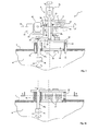
- the figure 3a shows a second embodiment of the invention. This mode differs from the previous one by the body structure 4b of the panoramic viewfinder 4.
- the aim sought here was to fix the cupola 1 according to the invention to a hatch 22 which is pivotally mounted relative to a vertical axis 23 (which is close to an edge of the hatch 22) to allow the opening of an access passage 24 inside the vehicle 8.
- the latter comprises a body 4b comprising two parallel vertical parts 4b 1 and 4b 2 which are connected to each other by a horizontal portion 4b 3 .
- the viewfinder 4 is here a viewfinder comprising an optical channel.
- the vertical portions 4b 1 and 4b 2 are optically connected to each other by optical return means 25, for example prisms or mirrors.
- the panoramic viewfinder 4 thus comprises an optical channel which is coaxial with the axis 23 of pivoting of the hatch 22.
- the vision capabilities conferred by the panoramic viewfinder 4 are not limited or disturbed by the opening of the hatch 22.
- Locking means and possibly an opening operator may be provided and have not been shown in the figures.
- This dome will advantageously wear a crown of episcopes 21 regularly distributed angularly which will ensure a near vision of good quality.
- the near vision provided by the episcopes 21 is not hindered by the mounting and the movement of the cupola 1.
- FIGS. 4a and 4b show an alternative embodiment in which the episcopes 21 are replaced by portholes or transparent walls 27 carried by the cylindrical wall of the dome 26.
- These portholes will be made of armored glass. They will further improve the peripheral vision close to the occupants of the vehicle.
- Turrets bearing small arms have been shown in the various figures. It is understood that a cupola according to the invention could carry other types of equipment, for example a missile launcher.
Landscapes
- Engineering & Computer Science (AREA)
- General Engineering & Computer Science (AREA)
- Aiming, Guidance, Guns With A Light Source, Armor, Camouflage, And Targets (AREA)
- Telescopes (AREA)
Abstract
Description
- Le domaine technique de l'invention est celui des tourelleaux permettant le montage d'un équipement, par exemple un armement secondaire, sur une tourelle de véhicule blindé.
- Des tourelleaux portant un armement secondaire équipent fréquemment les tourelles de véhicules blindés. Il existe par ailleurs des tourelleaux portant d'autres types d'équipements, par exemple des moyens de défense rapprochée (lanceurs de munitions fumigènes par exemple) ou bien des moyens d'observation ou de communication.
- Ces tourelleaux comportent le plus souvent une arme de petit calibre (inférieur à 14 mm) qui est associée à des moyens de visée optroniques.
- Ils sont pivotables en site et en gisement pour permettre l'observation ou l'engagement de cibles indépendamment de la position de la tourelle principale. Les tourelleaux peuvent aussi porter plusieurs armes, voire des tubes de lancement de missiles ou de roquettes.
- Le brevet
US5036748 décrit un tel type de tourelleau. - Les tourelleaux classiques présentent comme inconvénient d'obturer partiellement le champ de vision du chef de véhicule.
- Ce dernier dispose en effet le plus souvent d'un viseur optique pivotable sur 360° et dont le champ de vision se trouve limité par la présence du tourelleau.
- Par ailleurs les occupants du véhicule disposent également d'épiscopes répartis qui permettent d'observer l'espace rapproché autour du véhicule. Ces épiscopes sont généralement disposés très près de la paroi du véhicule et leur champ de vision est donc très perturbé par la mise en place d'un tourelleau.
- Des moyens optroniques peuvent dans une certaine mesure être utilisés pour observer les zones cachées mais ces moyens n'apportent pas généralement la qualité optique d'une vision directe et leur mise en oeuvre oblige au pointage de la tourelle vers le point observé ce qui dans des opérations de maintien de l'ordre peut apparaître comme une menace.
- L'invention a pour but de proposer une structure de tourelleau, permettant le montage d'un équipement tel un armement secondaire sur un véhicule blindé, tourelleau ne gênant pas par ailleurs les moyens de vision optique du véhicule, qu'il s'agisse des épiscopes ou bien du viseur optique panoramique.
- Ainsi l'invention a pour objet un tourelleau de montage d'un équipement, tel un armement secondaire, sur un véhicule blindé, tourelleau comprenant une plateforme pivotable en site et gisement par des moyens moteurs, tourelleau caractérisé en ce que la plateforme est fixée sur un manchon monté pivotant en gisement coaxialement à l'axe d'un viseur panoramique du véhicule comportant une tête positionnée au dessus de la plateforme et un corps médian cylindrique traversant la plateforme, la plateforme étant par ailleurs montée pivotante en site par rapport au manchon, la plateforme comportant pour cela une lumière autorisant son débattement en site par rapport au viseur panoramique.
- La plateforme pourra porter également un moyen de visée.
- Selon un mode de réalisation, la plateforme pourra être solidaire d'une trappe d'accès au véhicule.
- La trappe d'accès pourra être une trappe montée pivotante par rapport au véhicule sur un axe voisin d'un bord de la trappe.
- Le viseur panoramique du véhicule pourra alors comporter une voie qui sera coaxiale à l'axe de pivotement de la trappe. La voie coaxiale à l'axe de pivotement de la trappe pourra être une voie optique.
- Selon une variante de réalisation, la trappe pourra être disposée sur une coupole dotée d'une couronne de moyens de vision optiques.
- La plateforme pourra enfin porter au moins un deuxième équipement, tel un lanceur de missile.
- L'invention sera mieux comprise à la lecture du descriptif qui va suivre de différents modes de réalisation, descriptif établi en référence aux dessins annexés et dans lesquels :
- la
figure 1 est une vue frontale en coupe partielle d'un tourelleau selon un premier mode de réalisation de l'invention, - la
figure 2 est une vue de dessus de ce tourelleau, - la
figure 3 est une vue frontale en coupe partielle d'un tourelleau selon un second mode de réalisation de l'invention, - la
figure 4a est une vue frontale partielle de la partie inférieure d'une variante de réalisation d'un tourelleau selon l'invention, - la
figure 4b est une vue en coupe de cette variante, coupe réalisée suivant le plan dont la trace AA est repérée à lafigure 4a . - En se reportant à la
figure 1 , un tourelleau 1 selon l'invention comprend une plateforme 2 qui est fixée sur un manchon 3 monté d'une façon coaxiale à un viseur panoramique 4. - Le viseur panoramique 4 comprend d'une façon classique une tête 4a (renfermant un miroir de renvoi -non représenté- qui est mobile par rapport à un axe horizontal), un corps médian cylindrique 4b et un oculaire de vision 4c.
- Ces viseurs panoramiques permettent à l'équipage (et plus particulièrement au chef de véhicule) d'avoir une vision de l'espace externe entourant le véhicule. La vision est assurée sur 360° en raison du pivotement possible de la tête 4a par rapport au corps 4b. Ce pivotement est assuré d'une façon classique grâce à un petit moteur d'entraînement (non représenté).
- Le viseur panoramique 4 est de préférence un viseur optique car une telle technologie permet d'assurer une bonne visibilité quelle que soit la météorologie et elle permet des grossissements d'image sans perte de résolution.
- Le viseur panoramique 4 pourra également comporter une voie numérique, en particulier une voie de vision nocturne infrarouge ou encore une voie d'intensification de lumière. De tels viseurs sont bien connus de l'Homme du Métier et il n'est donc pas nécessaire de les décrire plus en détails. A titre d'exemple, les brevets
FR2714162 FR2686429 FR2656079 - Le viseur 4 est disposé dans un support cylindrique 5 qui est solidaire d'un panneau 6 obturant une paroi supérieure 7 d'une tourelle de véhicule 8. Le support 5 pourrait être directement solidaire du toit du véhicule.
- Suivant le mode de réalisation qui est décrit ici, le panneau est monté de façon fixe sur la paroi 7. Il serait cependant possible de monter le tourelleau 1 sur un panneau mobile obturant un passage permettant l'accès au véhicule.
- Le manchon 3 de la plateforme est monté pivotant sur le support 5. Le montage est réalisé par exemple à l'aide de roulements et butées 9. Ainsi la plateforme 2 peut pivoter en gisement autour de l'axe vertical 10 qui est aussi l'axe du viseur panoramique 4.
- Le pivotement en gisement est commandé par une première motorisation 11 qui est solidaire du panneau 6 et qui comprend un pignon 11a engrenant sur une couronne dentée cylindrique 12 solidaire du manchon 3.
- Le pivotement de la plateforme 2 peut ainsi être effectué pratiquement sur 360° (sous réserve de limitations imposées par des passages de câbles non représentés).
- La plateforme 2 est par exemple formée par une structure de tôles mécano soudées. Elle porte d'un côté une arme 13 de petit calibre (par exemple de 12,7 millimètres), dont on n'a représenté sur les figures que le corps 13a et le canon 13b. Un rebord 2a de la plateforme 2 supporte un magasin de munitions 14 qui est relié à l'arme par des couloirs (non représentés).
- De l'autre côté de l'axe 10, la plateforme 2 porte un moyen de visée optronique 15, par exemple une caméra. Ce moyen de visée 15 est parallèle à l'axe du tube 13b de l'arme. Il permet d'assurer la conduite du tir de l'arme 13.
- La plateforme 2 est montée basculante en site par rapport au manchon 3 au niveau de tourillons 16 qui matérialisent un axe (horizontal) de pointage en site 20, perpendiculaire à l'axe vertical 10.
- Une telle disposition permet d'assurer le pointage en site de l'arme 13. La commande du pointage est effectuée par une deuxième motorisation 17 qui est solidaire de la plateforme 2. La motorisation comprend par exemple un pignon engrenant sur une roue dentée 18 solidaire d'un tourillon 16.
- Afin d'autoriser le débattement en site de la plateforme 2, cette dernière porte une lumière 19 (
figure 2 ) au travers de laquelle passe le corps 4b du viseur panoramique 4. Les dimensions de la lumière 19 permettront de définir les angles maximaux de débattement en site autorisés. On pourra autoriser un pointage en site variant par exemple entre -15° et +45° par rapport l'horizontale. - On remarque enfin sur les
figures 1 et 2 , que des épiscopes 21 sont répartis autour du panneau 6. Ces épiscopes permettent de donner aux occupants du véhicule une capacité de vision de proximité. - On remarque que, grâce à l'invention, la plateforme 2 du tourelleau est située en dessous de la tête 4a du viseur panoramique. Le tourelleau 1 ne limite donc pas la capacité de vision donnée par ce viseur, et cela quel que soit l'angle de pointage en site ou en gisement du tourelleau.
- Inversement les épiscopes 21 sont situés en dessous de la plateforme 2. Leur champ de vision (en particulier rapproché) n'est donc pas non plus limité par le tourelleau 1.
- L'invention assure donc un montage très compact d'un système d'arme de petit calibre avec une capacité de pointage en site et gisement étendue, tout en ne limitant pas les champs de vision des moyens optiques du véhicule.
- On notera que le viseur panoramique 4 peut être pointé par le chef du véhicule vers un objectif d'une façon indépendante du pointage de la plateforme 2 (cela grâce à la tête pivotante 4a). Le système d'arme 13 n'est donc pas lui-même pointé vers l'objectif ce qui évite toute attitude menaçante lors d'une phase d'observation. Il n'est par ailleurs pas nécessaire non plus d'orienter la tourelle principale (non représentée) et qui porte une arme de plus gros calibre vers l'objectif lors de cette phase d'observation.
- La
figure 3a montre un deuxième mode de réalisation de l'invention. Ce mode diffère du précédent par la structure du corps 4b du viseur panoramique 4. - Le but recherché ici a été de fixer le tourelleau 1 selon l'invention à une trappe 22 qui est montée pivotante par rapport à un axe vertical 23 (qui est voisin d'un bord de la trappe 22) pour permettre l'ouverture d'un passage d'accès 24 à l'intérieur du véhicule 8.
- Afin d'autoriser un tel pivotement sans interférences mécaniques avec le viseur panoramique 4, ce dernier comporte un corps 4b comprenant deux parties verticales parallèles 4b1 et 4b2 qui sont reliées l'une à l'autre par une partie horizontale 4b3.
- Le viseur 4 est ici un viseur comportant une voie optique. Ainsi les parties verticales 4b1 et 4b2 sont reliées optiquement l'une à l'autre par des moyens de renvoi optique 25, par exemple des prismes ou bien des miroirs.
- Le viseur panoramique 4 comporte donc une voie optique qui est coaxiale à l'axe 23 de pivotement de la trappe 22.
- Les capacités de vision conférées par le viseur panoramique 4 ne sont donc pas limitées ou perturbées par l'ouverture de la trappe 22.
- Des moyens de verrouillage et éventuellement une motorisation d'ouverture pourront être prévus et n'ont pas été représentés sur les figures.
- On voit sur la
figure 3 que la trappe 22 est disposée sur une coupole cylindrique 26 qui est en saillie au-dessus de la paroi 7 du véhicule 8. - Cette coupole portera avantageusement une couronne d'épiscopes 21 régulièrement répartis angulairement ce qui assurera une vision de près de bonne qualité.
- Comme dans le mode de réalisation précédent, la vision de près assurée par les épiscopes 21 n'est pas gênée par le montage et le débattement du tourelleau 1.
- Les
figures 4a et4b montrent une variante de réalisation dans laquelle les épiscopes 21 sont remplacés par des hublots ou parois transparentes 27 portés par la paroi cylindrique de la coupole 26. Ces hublots seront réalisés en verre blindé. Ils permettront d'améliorer encore la vision périphérique proche des occupants du véhicule. - Diverses variantes sont possibles sans sortir du cadre de l'invention. On a ainsi représenté sur les différentes figures des tourelleaux portant une arme de petit calibre. I1 est bien entendu qu'un tourelleau selon l'invention pourrait porter d'autres types d'équipements, par exemple un lanceur de missiles.
- On pourra par ailleurs réaliser un tourelleau portant, d'un côté une arme de petit calibre, et de l'autre côté (sur les figures du côté du moyen de visée optronique 15) un deuxième équipement, tel un lanceur de missile.
Claims (8)
- Tourelleau (1) de montage d'un équipement, tel un armement secondaire (13), sur un véhicule blindé, tourelleau comprenant une plateforme (2) pivotable en site et gisement par des moyens moteurs (11,17), tourelleau caractérisé en ce que la plateforme (2) est fixée sur un manchon (3) monté pivotant en gisement coaxialement à l'axe (10) d'un viseur panoramique (4) du véhicule comportant une tête (4a) positionnée au dessus de la plateforme (2) et un corps médian cylindrique (4b) traversant la plateforme (2), la plateforme (2) étant par ailleurs montée pivotante en site par rapport au manchon (3), la plateforme comportant pour cela une lumière (19) autorisant son débattement en site par rapport au viseur panoramique (4).
- Tourelleau de montage d'équipement selon la revendication 1, caractérisé en ce que la plateforme (2) porte également un moyen de visée (15).
- Tourelleau de montage d'équipement selon une des revendications 1 ou 2, caractérisé en ce que la plateforme (2) est solidaire d'une trappe (22) d'accès au véhicule.
- Tourelleau de montage d'équipement selon la revendication 3, caractérisé en ce que la trappe d'accès (22) est une trappe montée pivotante par rapport au véhicule sur un axe (23) voisin d'un bord de la trappe (22).
- Tourelleau de montage d'équipement selon la revendication 4, caractérisé en ce que le viseur panoramique (4) du véhicule comporte une voie qui est coaxiale à l'axe (23) de pivotement de la trappe (22).
- Tourelleau de montage d'équipement selon la revendication 4, caractérisé en ce que la voie coaxiale à l'axe (23) de pivotement de la trappe est une voie optique.
- Tourelleau de montage d'équipement selon une des revendications 1 ou 2, caractérisé en ce que la trappe (22) est disposée sur une coupole (26) dotée d'une couronne de moyens de vision optiques (21,27).
- Tourelleau de montage d'équipement selon une des revendications 1 à 7, caractérisé en ce que la plateforme (2) porte au moins un deuxième équipement, tel un lanceur de missile.
Priority Applications (1)
| Application Number | Priority Date | Filing Date | Title |
|---|---|---|---|
| PL10290325T PL2306137T3 (pl) | 2009-10-01 | 2010-06-16 | Wieżyczka do mocowania wyposażenia takiego jak broń pomocnicza |
Applications Claiming Priority (1)
| Application Number | Priority Date | Filing Date | Title |
|---|---|---|---|
| FR0904725A FR2950962B1 (fr) | 2009-10-01 | 2009-10-01 | Tourelleau de montage d'un equipement, tel un armement secondaire |
Publications (2)
| Publication Number | Publication Date |
|---|---|
| EP2306137A1 true EP2306137A1 (fr) | 2011-04-06 |
| EP2306137B1 EP2306137B1 (fr) | 2013-05-29 |
Family
ID=42104706
Family Applications (1)
| Application Number | Title | Priority Date | Filing Date |
|---|---|---|---|
| EP10290325.9A Active EP2306137B1 (fr) | 2009-10-01 | 2010-06-16 | Tourelleau de montage d'un équipement tel un armement secondaire |
Country Status (3)
| Country | Link |
|---|---|
| EP (1) | EP2306137B1 (fr) |
| FR (1) | FR2950962B1 (fr) |
| PL (1) | PL2306137T3 (fr) |
Cited By (6)
| Publication number | Priority date | Publication date | Assignee | Title |
|---|---|---|---|---|
| WO2011131183A1 (fr) * | 2010-04-21 | 2011-10-27 | Krauss-Maffei Wegmann Gmbh & Co. Kg | Véhicule comprenant un affût de tourelle, un affût supplémentaire et un appareil de visualisation disposé sur l'affût supplémentaire |
| WO2012015777A1 (fr) * | 2010-07-27 | 2012-02-02 | Raytheon Company | Poste d'armes et procédé associé |
| DE102012002043A1 (de) * | 2012-02-02 | 2013-08-08 | Diehl Bgt Defence Gmbh & Co. Kg | Waffenbasierte Schutzeinrichtung für Fahrzeuge |
| WO2015144937A1 (fr) * | 2014-03-28 | 2015-10-01 | Sagem Defense Securite | Tourelleau optronique arme |
| EP3029409A1 (fr) | 2014-12-05 | 2016-06-08 | NEXTER Systems | Tourelleau pour arme de petit calibre |
| RU2813389C1 (ru) * | 2023-01-19 | 2024-02-12 | Общество с ограниченной ответственностью "НЕЙРОТЕХ" | Устройство защиты от беспилотных летательных аппаратов |
Citations (9)
| Publication number | Priority date | Publication date | Assignee | Title |
|---|---|---|---|---|
| GB1055480A (en) * | 1963-12-05 | 1967-01-18 | Ruf Walter | Weapon mountings |
| FR1470459A (fr) * | 1965-03-01 | 1967-02-24 | Fmc Corp | Ensemble de montage et de viseur pour canon |
| FR2656079A1 (fr) | 1989-12-20 | 1991-06-21 | France Etat Armement | Lunette episcopique modulable et reconfigurable. |
| US5036748A (en) | 1988-07-20 | 1991-08-06 | The Marconi Company Limited | Weapon system |
| FR2686429A1 (fr) | 1992-01-22 | 1993-07-23 | Giat Ind Sa | Systeme de visee optique pour controler le debattement angulaire d'un appareil mobile en rotation sur un axe. |
| FR2714162A1 (fr) | 1993-12-22 | 1995-06-23 | Giat Ind Sa | Dispositif de visée intégrant une voie épiscopique. |
| WO2004036138A1 (fr) * | 2002-10-10 | 2004-04-29 | Krauss-Maffei Wegmann Gmbh & Co. Kg | Dispositif pour protéger des objets contre des munitions en forme de projectiles guidés |
| EP1591746A1 (fr) * | 2004-04-29 | 2005-11-02 | Krauss-Maffei Wegmann GmbH & Co. KG | Vehicule blindé, en particulier char |
| US20080034954A1 (en) * | 2005-01-31 | 2008-02-14 | David Ehrlich Grober | Stabilizing mount for hands-on and remote operation of cameras, sensors, computer intelligent devices and weapons |
-
2009
- 2009-10-01 FR FR0904725A patent/FR2950962B1/fr not_active Expired - Fee Related
-
2010
- 2010-06-16 PL PL10290325T patent/PL2306137T3/pl unknown
- 2010-06-16 EP EP10290325.9A patent/EP2306137B1/fr active Active
Patent Citations (9)
| Publication number | Priority date | Publication date | Assignee | Title |
|---|---|---|---|---|
| GB1055480A (en) * | 1963-12-05 | 1967-01-18 | Ruf Walter | Weapon mountings |
| FR1470459A (fr) * | 1965-03-01 | 1967-02-24 | Fmc Corp | Ensemble de montage et de viseur pour canon |
| US5036748A (en) | 1988-07-20 | 1991-08-06 | The Marconi Company Limited | Weapon system |
| FR2656079A1 (fr) | 1989-12-20 | 1991-06-21 | France Etat Armement | Lunette episcopique modulable et reconfigurable. |
| FR2686429A1 (fr) | 1992-01-22 | 1993-07-23 | Giat Ind Sa | Systeme de visee optique pour controler le debattement angulaire d'un appareil mobile en rotation sur un axe. |
| FR2714162A1 (fr) | 1993-12-22 | 1995-06-23 | Giat Ind Sa | Dispositif de visée intégrant une voie épiscopique. |
| WO2004036138A1 (fr) * | 2002-10-10 | 2004-04-29 | Krauss-Maffei Wegmann Gmbh & Co. Kg | Dispositif pour protéger des objets contre des munitions en forme de projectiles guidés |
| EP1591746A1 (fr) * | 2004-04-29 | 2005-11-02 | Krauss-Maffei Wegmann GmbH & Co. KG | Vehicule blindé, en particulier char |
| US20080034954A1 (en) * | 2005-01-31 | 2008-02-14 | David Ehrlich Grober | Stabilizing mount for hands-on and remote operation of cameras, sensors, computer intelligent devices and weapons |
Cited By (14)
| Publication number | Priority date | Publication date | Assignee | Title |
|---|---|---|---|---|
| WO2011131183A1 (fr) * | 2010-04-21 | 2011-10-27 | Krauss-Maffei Wegmann Gmbh & Co. Kg | Véhicule comprenant un affût de tourelle, un affût supplémentaire et un appareil de visualisation disposé sur l'affût supplémentaire |
| US8646374B2 (en) | 2010-07-27 | 2014-02-11 | Raytheon Company | Weapon station and associated method |
| WO2012015777A1 (fr) * | 2010-07-27 | 2012-02-02 | Raytheon Company | Poste d'armes et procédé associé |
| EP2598824B1 (fr) | 2010-07-27 | 2017-11-15 | Raytheon Company | Poste d'armes et procédé associé |
| DE102012002043B4 (de) * | 2012-02-02 | 2014-01-16 | Diehl Bgt Defence Gmbh & Co. Kg | Waffenbasierte Schutzeinrichtung für Fahrzeuge |
| DE102012002043C5 (de) * | 2012-02-02 | 2016-05-12 | Diehl Bgt Defence Gmbh & Co. Kg | Waffenbasierte Schutzeinrichtung für Fahrzeuge |
| DE102012002043A1 (de) * | 2012-02-02 | 2013-08-08 | Diehl Bgt Defence Gmbh & Co. Kg | Waffenbasierte Schutzeinrichtung für Fahrzeuge |
| WO2015144937A1 (fr) * | 2014-03-28 | 2015-10-01 | Sagem Defense Securite | Tourelleau optronique arme |
| FR3019279A1 (fr) * | 2014-03-28 | 2015-10-02 | Sagem Defense Securite | Tourelleau optronique arme |
| EP3123097B1 (fr) | 2014-03-28 | 2018-05-09 | Safran Electronics & Defense | Tourelleau optronique arme |
| RU2672454C2 (ru) * | 2014-03-28 | 2018-11-14 | Сафран Электроникс Энд Дифенс | Вооруженная оптоэлектронная турель |
| AU2015238173B2 (en) * | 2014-03-28 | 2018-12-13 | Safran Electronics & Defense | Armed optoelectronic turret |
| EP3029409A1 (fr) | 2014-12-05 | 2016-06-08 | NEXTER Systems | Tourelleau pour arme de petit calibre |
| RU2813389C1 (ru) * | 2023-01-19 | 2024-02-12 | Общество с ограниченной ответственностью "НЕЙРОТЕХ" | Устройство защиты от беспилотных летательных аппаратов |
Also Published As
| Publication number | Publication date |
|---|---|
| PL2306137T3 (pl) | 2013-10-31 |
| FR2950962A1 (fr) | 2011-04-08 |
| EP2306137B1 (fr) | 2013-05-29 |
| FR2950962B1 (fr) | 2011-10-14 |
Similar Documents
| Publication | Publication Date | Title |
|---|---|---|
| EP2306137B1 (fr) | Tourelleau de montage d'un équipement tel un armement secondaire | |
| FR2940246A1 (fr) | Dispositif de tir de munition a partir d'un drone arme | |
| EP3123100B1 (fr) | Viseur optronique a blindage modulable | |
| WO2021130605A1 (fr) | Dispositif lanceur de munitions | |
| EP2669617A1 (fr) | Tourelle modulaire pour véhicule blindé et char de combat | |
| EP3155358B1 (fr) | Systeme de guidage de missiles pour vehicules et cibles mobiles | |
| EP0435771A1 (fr) | Tourelle pour blindé léger équipée d'une arme latérale | |
| WO1997005442A1 (fr) | Systeme de pointage d'une arme a feu montee sur un engin blinde par exemple | |
| FR2705770A1 (fr) | Dispositif à silencieux pour armes à tube. | |
| FR2549218A1 (fr) | Vehicule blinde equipe d'un mortier | |
| FR2514489A1 (fr) | Vehicule blinde | |
| FR2459447A1 (fr) | Perfectionnements aux tourelles blindees munies d'un tourelleau | |
| FR2654819A1 (fr) | Affut pour une arme legere sur des vehicules blindes. | |
| EP2163843B1 (fr) | Tourelleau escamotable | |
| EP4317903B1 (fr) | Montage d'arme et tourelle comportant un tel montage d'arme | |
| FR3060142A1 (fr) | Appareil de visee pour vehicule et vehicule associe | |
| BE1020527A3 (fr) | Tourelle modulaire pour vehicule blinde et char de combat. | |
| FR3022338A1 (fr) | Tourelleau comportant un magasin a munitions | |
| EP3877718B1 (fr) | Montage d'arme et tourelle comportant un tel montage | |
| RU2222759C2 (ru) | Гранатометная установка | |
| FR2943126A1 (fr) | Vehicule blinde equipe d'une tourelle et tourelle pour un tel vehicule | |
| EP2956738B1 (fr) | Systeme d'arme leger | |
| EP0140053A2 (fr) | Mortier capable d'être monté sur un véhicule | |
| FR2656084A1 (fr) | Perfectionnements aux projectiles antichars agissant en survol de l'objectif avec basculement. | |
| FR2522132A1 (fr) | Dispositif de reperage horizontal d'un periscope monte sur un tube d'une piece d'artillerie |
Legal Events
| Date | Code | Title | Description |
|---|---|---|---|
| PUAI | Public reference made under article 153(3) epc to a published international application that has entered the european phase |
Free format text: ORIGINAL CODE: 0009012 |
|
| AK | Designated contracting states |
Kind code of ref document: A1 Designated state(s): AL AT BE BG CH CY CZ DE DK EE ES FI FR GB GR HR HU IE IS IT LI LT LU LV MC MK MT NL NO PL PT RO SE SI SK SM TR |
|
| AX | Request for extension of the european patent |
Extension state: BA ME RS |
|
| 17P | Request for examination filed |
Effective date: 20111006 |
|
| GRAP | Despatch of communication of intention to grant a patent |
Free format text: ORIGINAL CODE: EPIDOSNIGR1 |
|
| RIC1 | Information provided on ipc code assigned before grant |
Ipc: F41A 23/34 20060101ALI20121130BHEP Ipc: F41A 27/18 20060101ALI20121130BHEP Ipc: F41A 27/06 20060101ALI20121130BHEP Ipc: F41A 27/08 20060101ALI20121130BHEP Ipc: F41G 1/40 20060101AFI20121130BHEP Ipc: F41H 5/26 20060101ALI20121130BHEP Ipc: F41A 23/24 20060101ALI20121130BHEP |
|
| GRAS | Grant fee paid |
Free format text: ORIGINAL CODE: EPIDOSNIGR3 |
|
| GRAA | (expected) grant |
Free format text: ORIGINAL CODE: 0009210 |
|
| AK | Designated contracting states |
Kind code of ref document: B1 Designated state(s): AL AT BE BG CH CY CZ DE DK EE ES FI FR GB GR HR HU IE IS IT LI LT LU LV MC MK MT NL NO PL PT RO SE SI SK SM TR |
|
| REG | Reference to a national code |
Ref country code: GB Ref legal event code: FG4D Free format text: NOT ENGLISH |
|
| REG | Reference to a national code |
Ref country code: CH Ref legal event code: EP |
|
| REG | Reference to a national code |
Ref country code: AT Ref legal event code: REF Ref document number: 614666 Country of ref document: AT Kind code of ref document: T Effective date: 20130615 |
|
| REG | Reference to a national code |
Ref country code: IE Ref legal event code: FG4D Free format text: LANGUAGE OF EP DOCUMENT: FRENCH |
|
| REG | Reference to a national code |
Ref country code: DE Ref legal event code: R096 Ref document number: 602010007299 Country of ref document: DE Effective date: 20130725 |
|
| REG | Reference to a national code |
Ref country code: SE Ref legal event code: TRGR |
|
| REG | Reference to a national code |
Ref country code: NO Ref legal event code: T2 Effective date: 20130529 |
|
| REG | Reference to a national code |
Ref country code: AT Ref legal event code: MK05 Ref document number: 614666 Country of ref document: AT Kind code of ref document: T Effective date: 20130529 |
|
| REG | Reference to a national code |
Ref country code: LT Ref legal event code: MG4D |
|
| PG25 | Lapsed in a contracting state [announced via postgrant information from national office to epo] |
Ref country code: SI Free format text: LAPSE BECAUSE OF FAILURE TO SUBMIT A TRANSLATION OF THE DESCRIPTION OR TO PAY THE FEE WITHIN THE PRESCRIBED TIME-LIMIT Effective date: 20130529 Ref country code: FI Free format text: LAPSE BECAUSE OF FAILURE TO SUBMIT A TRANSLATION OF THE DESCRIPTION OR TO PAY THE FEE WITHIN THE PRESCRIBED TIME-LIMIT Effective date: 20130529 Ref country code: GR Free format text: LAPSE BECAUSE OF FAILURE TO SUBMIT A TRANSLATION OF THE DESCRIPTION OR TO PAY THE FEE WITHIN THE PRESCRIBED TIME-LIMIT Effective date: 20130830 Ref country code: LT Free format text: LAPSE BECAUSE OF FAILURE TO SUBMIT A TRANSLATION OF THE DESCRIPTION OR TO PAY THE FEE WITHIN THE PRESCRIBED TIME-LIMIT Effective date: 20130529 Ref country code: AT Free format text: LAPSE BECAUSE OF FAILURE TO SUBMIT A TRANSLATION OF THE DESCRIPTION OR TO PAY THE FEE WITHIN THE PRESCRIBED TIME-LIMIT Effective date: 20130529 Ref country code: PT Free format text: LAPSE BECAUSE OF FAILURE TO SUBMIT A TRANSLATION OF THE DESCRIPTION OR TO PAY THE FEE WITHIN THE PRESCRIBED TIME-LIMIT Effective date: 20130930 Ref country code: IS Free format text: LAPSE BECAUSE OF FAILURE TO SUBMIT A TRANSLATION OF THE DESCRIPTION OR TO PAY THE FEE WITHIN THE PRESCRIBED TIME-LIMIT Effective date: 20130929 Ref country code: ES Free format text: LAPSE BECAUSE OF FAILURE TO SUBMIT A TRANSLATION OF THE DESCRIPTION OR TO PAY THE FEE WITHIN THE PRESCRIBED TIME-LIMIT Effective date: 20130909 |
|
| REG | Reference to a national code |
Ref country code: PL Ref legal event code: T3 |
|
| REG | Reference to a national code |
Ref country code: NL Ref legal event code: VDEP Effective date: 20130529 |
|
| PG25 | Lapsed in a contracting state [announced via postgrant information from national office to epo] |
Ref country code: HR Free format text: LAPSE BECAUSE OF FAILURE TO SUBMIT A TRANSLATION OF THE DESCRIPTION OR TO PAY THE FEE WITHIN THE PRESCRIBED TIME-LIMIT Effective date: 20130529 Ref country code: BG Free format text: LAPSE BECAUSE OF FAILURE TO SUBMIT A TRANSLATION OF THE DESCRIPTION OR TO PAY THE FEE WITHIN THE PRESCRIBED TIME-LIMIT Effective date: 20130829 |
|
| PG25 | Lapsed in a contracting state [announced via postgrant information from national office to epo] |
Ref country code: LV Free format text: LAPSE BECAUSE OF FAILURE TO SUBMIT A TRANSLATION OF THE DESCRIPTION OR TO PAY THE FEE WITHIN THE PRESCRIBED TIME-LIMIT Effective date: 20130529 |
|
| PG25 | Lapsed in a contracting state [announced via postgrant information from national office to epo] |
Ref country code: SK Free format text: LAPSE BECAUSE OF FAILURE TO SUBMIT A TRANSLATION OF THE DESCRIPTION OR TO PAY THE FEE WITHIN THE PRESCRIBED TIME-LIMIT Effective date: 20130529 Ref country code: EE Free format text: LAPSE BECAUSE OF FAILURE TO SUBMIT A TRANSLATION OF THE DESCRIPTION OR TO PAY THE FEE WITHIN THE PRESCRIBED TIME-LIMIT Effective date: 20130529 Ref country code: DK Free format text: LAPSE BECAUSE OF FAILURE TO SUBMIT A TRANSLATION OF THE DESCRIPTION OR TO PAY THE FEE WITHIN THE PRESCRIBED TIME-LIMIT Effective date: 20130529 Ref country code: CZ Free format text: LAPSE BECAUSE OF FAILURE TO SUBMIT A TRANSLATION OF THE DESCRIPTION OR TO PAY THE FEE WITHIN THE PRESCRIBED TIME-LIMIT Effective date: 20130529 |
|
| PG25 | Lapsed in a contracting state [announced via postgrant information from national office to epo] |
Ref country code: RO Free format text: LAPSE BECAUSE OF FAILURE TO SUBMIT A TRANSLATION OF THE DESCRIPTION OR TO PAY THE FEE WITHIN THE PRESCRIBED TIME-LIMIT Effective date: 20130529 Ref country code: MC Free format text: LAPSE BECAUSE OF FAILURE TO SUBMIT A TRANSLATION OF THE DESCRIPTION OR TO PAY THE FEE WITHIN THE PRESCRIBED TIME-LIMIT Effective date: 20130529 Ref country code: NL Free format text: LAPSE BECAUSE OF FAILURE TO SUBMIT A TRANSLATION OF THE DESCRIPTION OR TO PAY THE FEE WITHIN THE PRESCRIBED TIME-LIMIT Effective date: 20130529 |
|
| REG | Reference to a national code |
Ref country code: IE Ref legal event code: MM4A |
|
| PLBE | No opposition filed within time limit |
Free format text: ORIGINAL CODE: 0009261 |
|
| STAA | Information on the status of an ep patent application or granted ep patent |
Free format text: STATUS: NO OPPOSITION FILED WITHIN TIME LIMIT |
|
| PG25 | Lapsed in a contracting state [announced via postgrant information from national office to epo] |
Ref country code: IE Free format text: LAPSE BECAUSE OF NON-PAYMENT OF DUE FEES Effective date: 20130616 |
|
| 26N | No opposition filed |
Effective date: 20140303 |
|
| REG | Reference to a national code |
Ref country code: DE Ref legal event code: R097 Ref document number: 602010007299 Country of ref document: DE Effective date: 20140303 |
|
| REG | Reference to a national code |
Ref country code: CH Ref legal event code: PL |
|
| PG25 | Lapsed in a contracting state [announced via postgrant information from national office to epo] |
Ref country code: MT Free format text: LAPSE BECAUSE OF FAILURE TO SUBMIT A TRANSLATION OF THE DESCRIPTION OR TO PAY THE FEE WITHIN THE PRESCRIBED TIME-LIMIT Effective date: 20130529 |
|
| PG25 | Lapsed in a contracting state [announced via postgrant information from national office to epo] |
Ref country code: CH Free format text: LAPSE BECAUSE OF NON-PAYMENT OF DUE FEES Effective date: 20140630 Ref country code: LI Free format text: LAPSE BECAUSE OF NON-PAYMENT OF DUE FEES Effective date: 20140630 |
|
| PG25 | Lapsed in a contracting state [announced via postgrant information from national office to epo] |
Ref country code: SM Free format text: LAPSE BECAUSE OF FAILURE TO SUBMIT A TRANSLATION OF THE DESCRIPTION OR TO PAY THE FEE WITHIN THE PRESCRIBED TIME-LIMIT Effective date: 20130529 |
|
| PG25 | Lapsed in a contracting state [announced via postgrant information from national office to epo] |
Ref country code: CY Free format text: LAPSE BECAUSE OF FAILURE TO SUBMIT A TRANSLATION OF THE DESCRIPTION OR TO PAY THE FEE WITHIN THE PRESCRIBED TIME-LIMIT Effective date: 20130529 |
|
| PG25 | Lapsed in a contracting state [announced via postgrant information from national office to epo] |
Ref country code: MK Free format text: LAPSE BECAUSE OF FAILURE TO SUBMIT A TRANSLATION OF THE DESCRIPTION OR TO PAY THE FEE WITHIN THE PRESCRIBED TIME-LIMIT Effective date: 20130529 Ref country code: LU Free format text: LAPSE BECAUSE OF NON-PAYMENT OF DUE FEES Effective date: 20130616 Ref country code: HU Free format text: LAPSE BECAUSE OF FAILURE TO SUBMIT A TRANSLATION OF THE DESCRIPTION OR TO PAY THE FEE WITHIN THE PRESCRIBED TIME-LIMIT; INVALID AB INITIO Effective date: 20100616 |
|
| REG | Reference to a national code |
Ref country code: FR Ref legal event code: PLFP Year of fee payment: 7 |
|
| REG | Reference to a national code |
Ref country code: FR Ref legal event code: PLFP Year of fee payment: 8 |
|
| REG | Reference to a national code |
Ref country code: FR Ref legal event code: PLFP Year of fee payment: 9 |
|
| PG25 | Lapsed in a contracting state [announced via postgrant information from national office to epo] |
Ref country code: AL Free format text: LAPSE BECAUSE OF FAILURE TO SUBMIT A TRANSLATION OF THE DESCRIPTION OR TO PAY THE FEE WITHIN THE PRESCRIBED TIME-LIMIT Effective date: 20130529 |
|
| PGFP | Annual fee paid to national office [announced via postgrant information from national office to epo] |
Ref country code: SE Payment date: 20190527 Year of fee payment: 10 Ref country code: TR Payment date: 20190530 Year of fee payment: 10 |
|
| PGFP | Annual fee paid to national office [announced via postgrant information from national office to epo] |
Ref country code: GB Payment date: 20190522 Year of fee payment: 10 |
|
| GBPC | Gb: european patent ceased through non-payment of renewal fee |
Effective date: 20200616 |
|
| PG25 | Lapsed in a contracting state [announced via postgrant information from national office to epo] |
Ref country code: GB Free format text: LAPSE BECAUSE OF NON-PAYMENT OF DUE FEES Effective date: 20200616 |
|
| PG25 | Lapsed in a contracting state [announced via postgrant information from national office to epo] |
Ref country code: SE Free format text: LAPSE BECAUSE OF NON-PAYMENT OF DUE FEES Effective date: 20200617 |
|
| REG | Reference to a national code |
Ref country code: SE Ref legal event code: EUG |
|
| PG25 | Lapsed in a contracting state [announced via postgrant information from national office to epo] |
Ref country code: TR Free format text: LAPSE BECAUSE OF NON-PAYMENT OF DUE FEES Effective date: 20200616 |
|
| PG25 | Lapsed in a contracting state [announced via postgrant information from national office to epo] |
Ref country code: PL Free format text: LAPSE BECAUSE OF NON-PAYMENT OF DUE FEES Effective date: 20200616 |
|
| PGFP | Annual fee paid to national office [announced via postgrant information from national office to epo] |
Ref country code: DE Payment date: 20250520 Year of fee payment: 16 |
|
| PGFP | Annual fee paid to national office [announced via postgrant information from national office to epo] |
Ref country code: NO Payment date: 20250522 Year of fee payment: 16 |
|
| PGFP | Annual fee paid to national office [announced via postgrant information from national office to epo] |
Ref country code: BE Payment date: 20250520 Year of fee payment: 16 Ref country code: IT Payment date: 20250520 Year of fee payment: 16 |
|
| PGFP | Annual fee paid to national office [announced via postgrant information from national office to epo] |
Ref country code: FR Payment date: 20250520 Year of fee payment: 16 |