EP2956738B1 - Systeme d'arme leger - Google Patents
Systeme d'arme leger Download PDFInfo
- Publication number
- EP2956738B1 EP2956738B1 EP14711805.3A EP14711805A EP2956738B1 EP 2956738 B1 EP2956738 B1 EP 2956738B1 EP 14711805 A EP14711805 A EP 14711805A EP 2956738 B1 EP2956738 B1 EP 2956738B1
- Authority
- EP
- European Patent Office
- Prior art keywords
- tube
- weapon system
- drawer
- mortar
- light weapon
- Prior art date
- Legal status (The legal status is an assumption and is not a legal conclusion. Google has not performed a legal analysis and makes no representation as to the accuracy of the status listed.)
- Active
Links
Images


Classifications
-
- F—MECHANICAL ENGINEERING; LIGHTING; HEATING; WEAPONS; BLASTING
- F41—WEAPONS
- F41F—APPARATUS FOR LAUNCHING PROJECTILES OR MISSILES FROM BARRELS, e.g. CANNONS; LAUNCHERS FOR ROCKETS OR TORPEDOES; HARPOON GUNS
- F41F1/00—Launching apparatus for projecting projectiles or missiles from barrels, e.g. cannons; Harpoon guns
- F41F1/06—Mortars
-
- F—MECHANICAL ENGINEERING; LIGHTING; HEATING; WEAPONS; BLASTING
- F41—WEAPONS
- F41A—FUNCTIONAL FEATURES OR DETAILS COMMON TO BOTH SMALLARMS AND ORDNANCE, e.g. CANNONS; MOUNTINGS FOR SMALLARMS OR ORDNANCE
- F41A23/00—Gun mountings, e.g. on vehicles; Disposition of guns on vehicles
- F41A23/24—Turret gun mountings
-
- F—MECHANICAL ENGINEERING; LIGHTING; HEATING; WEAPONS; BLASTING
- F41—WEAPONS
- F41A—FUNCTIONAL FEATURES OR DETAILS COMMON TO BOTH SMALLARMS AND ORDNANCE, e.g. CANNONS; MOUNTINGS FOR SMALLARMS OR ORDNANCE
- F41A9/00—Feeding or loading of ammunition; Magazines; Guiding means for the extracting of cartridges
- F41A9/38—Loading arrangements, i.e. for bringing the ammunition into the firing position
-
- F—MECHANICAL ENGINEERING; LIGHTING; HEATING; WEAPONS; BLASTING
- F41—WEAPONS
- F41H—ARMOUR; ARMOURED TURRETS; ARMOURED OR ARMED VEHICLES; MEANS OF ATTACK OR DEFENCE, e.g. CAMOUFLAGE, IN GENERAL
- F41H5/00—Armour; Armour plates
- F41H5/22—Manhole covers, e.g. on tanks; Doors on armoured vehicles or structures
- F41H5/223—Manhole covers specially adapted for armoured or fighting vehicles
Definitions
- the technical field of the invention is that of light weapon systems adaptable to a vehicle hatch.
- Armored vehicles for military use often include a panel of weapons adapted to their main mission.
- a tank that is a vehicle specialized in direct fire or tight fire, it includes a gun for direct anti-tank fire or anti infrastructure.
- This weapon is often associated with a secondary weapon of small or medium caliber intended for the direct fire antipersonnel or anti light material.
- the invention proposes a weapon system that can equip a vehicle, mortar-type weapon system that can be served from inside the vehicle and without causing a heavy impact on the architecture of the vehicle.
- the light weapon system comprises a closure means of the opening ensuring a ballistic protection.
- the closure means is secured to a loading means comprising a drawer intended to contain a shell, the slide being slidably mounted by a sliding connection in the opening of the riser.
- the drawer has a chute for passing the tube, the drawer pushing when sliding the shell in the mouth of the tube.
- the chute of the drawer is open in its upper part to let in and out of the drawer the mouth of the tube during positioning movements in site thereof.
- the light weapon system may include a site angle sensor for pointing up the tube.
- the firing means is a striker controllable from inside the vehicle and located in the cylinder head of the tube.
- the tube orientation means of the tube is an electric jack.
- a turret 100 of an armored vehicle (vehicle shown very schematically) comprises two manholes 101 and 102 intended to let in or out all or part of a crew member in a passenger compartment formed by the turret 100.
- Each manhole is closed by an articulated hatch 101a and 102a.
- One of the manholes 101 carries a light weapon system 1 according to the invention, which is intended to fire mortar shells.
- This weapon system 1 comprises a mortar tube 2 which is, according to the embodiment shown, oriented in parallel with the reference to the main weapon 100a of the turret 100.
- the bearing pointing of the weapon system 1 will therefore be carried out by rotating the turret or the entire vehicle.
- the weapon system 1 is fixed at the manhole by conventional fastening means, such as screws and / or bolts, other means may be used.
- the weapon system comprises a riser 3 which extends vertically above the manhole 101a (not visible hole).
- This enhancement 3 surrounds the entire periphery of the manhole.
- a support 4 of the mortar tube 2 is secured in a fixed manner at a first end of the riser 2, below a hinge 5 serving to open the hatch 6.
- the support 4 extending substantially horizontally in an interfacing plane P of the weapon system 1 on the manhole.
- the support 4 comprises at its second end a pivot connection 4b intended to allow the rotation of the tube 2 around the horizontal axis A to orient the tube 2 in place and thus adjust the rise.
- the support 4 comprises two lateral flanks 4a between which a front portion of the tube 2 having the mouth of the tube 2a can be placed when it is horizontal.
- the weapon system 1 comprises an orientation means 7 of the tube 2 in site.
- the orientation means 7 is an electric jack secured to a flank 4a of the support 4 and secured by another end of the pivot connection 4b connected to the tube 2 (for example by a connecting rod - crank system ).
- the second end of the jack may be integral with the tube 2 directly.
- This cylinder 7 is controllable from the cabin of the turret 100.
- the weapon system 1 comprises a measuring means (not shown) for the orientation of the tube 2.
- a measuring means for the orientation of the tube 2.
- Such means are well known to those skilled in the art, they may be constituted by an angular sensor for example or any other measuring means for indicating the value of pointing in site of the tube to a servant of the weapon system located in the cabin of the turret 100.
- the weapon system 1 is shown without its hatch or hinge to see the internal operation of the weapon system 1.
- the riser 3 has in its wall an opening 8 opening, towards the outside of the extension 3, between the flanks 4a of the support 4 and facing the mouth 2a of the tube 2 when it is at the horizontal.
- This opening 8 corresponds with a loading means 9 of the tube 2.
- This loading means may be a slide 9 which is slidably mounted by a sliding connection 10 in the opening 8, the sliding drawer of the inside of the riser 3 to outside and vice versa.
- the drawer 9 has on one of its sides a window 11 intended to allow to place a shell 12 inside the drawer 9.
- the shell 12 is placed so that its rear part is closest to the opening 8 so that this part subsequently enters the first in the mouth 2a of the tube 2 during the loading of the shell 12 as shown in FIG. figure 4 .
- the servant During loading, from the cabin of the turret 100, the servant has access to the drawer while being protected by the hatch 6 which closes the raiser (hatch not shown at the figure 4 ). It pushes the drawer towards the tube 2a, thus causing the shell 12 to enter the mouth of the tube 2a.
- the drawer 9 has a stretcher shape and therefore comprises a chute 9a which is dimensioned so as to allow the tube 2 to enter the drawer 9 when the latter is pushed to slide the shell 12 into the mouth 2a of the tube 2 .
- the chute 9a of the drawer 9 is also completely open in its upper part. Thus the tube can be rotated for its positioning in the site without being obstructed by the drawer 9.
- the slide 9 carries at its rear part a plate 9b ( figure 8 ) forming a closing means of the bottom of the opening 8.
- This plate 9b provides ballistic protection of the riser 3 after the tube tilted.
- a locking means (not shown) will lock the drawer 9 relative to the riser 3 in this position.
- the plate 9b will be made of a material having resistance capabilities similar to that of the riser 3 and will have a thickness of the same order as that of the riser.
- the drawer 9 is open on its upper part leaving the tube 2 apparent and free to move upwards.
- the servant controls the setting firing site from the inside of the turret by activating the cylinder 7.
- the tube 2 under the action of the orientation means 7, raises the mouth 2a of the tube which causes the descent of the shell at the bottom of the tube 2 by gravity.
- the servant can control the firing of the shell by means conventionally known to those skilled in the art such as a remotely controllable striker located in the cylinder head 2b of the tube 2.
- the weapon system According to a simpler embodiment of the weapon system according to the invention, it is conceivable not to equip the weapon system with a loading drawer. In this case, the shell will be inserted manually into the mouth of the tube through the opening 8.
- a pivoting flap may be provided to close the opening 8 but the ballistic seal is not guaranteed in this case during the loading phase.
- the small size of the opening 8 and its position protected by the flanks 4a of the support 4 provides a low exposure of the servant vis-à-vis the ballistic threats.
- the invention makes it possible to equip an armored vehicle with a light weapon system that can be safely served from the passenger compartment of the vehicle without causing the vehicle to be heavily modified.
- pivot connection 4b between the tube 2 and the support 4 is located cantilevered with respect to the turret nape. This allows the tube 2 to point in height without its breech interferes with the turret.
- the pivot connection 4b between the tube 2 and the support 4 is situated at the rear part of the tube, which avoids, during the raising of the tube 2, any interference with elements of the vehicle placed under the device 1.
Landscapes
- Engineering & Computer Science (AREA)
- General Engineering & Computer Science (AREA)
- Aiming, Guidance, Guns With A Light Source, Armor, Camouflage, And Targets (AREA)
Description
- Le domaine technique de l'invention est celui des systèmes d'arme légers adaptables à une trappe de véhicule.
- Les véhicules blindés à usage militaire comportent souvent un panel d'armes adaptées à leur mission principale. Dans le cas d'un char qui est un véhicule spécialisé dans le tir direct ou tir tendu, celui-ci comporte un canon pour le tir direct antichar ou anti infrastructures. Cette arme est souvent associée avec une arme secondaire de petit ou de moyen calibre destinée au tir direct antipersonnel ou anti matériels légers.
- Certaines missions demandent pourtant plus de polyvalence et une arme destinée au tir indirect ou tir balistique courbe est souhaitée. Pour cela il est connu d'équiper les personnels avec des mortiers légers (calibre 40 à 80 mm) ou des lance grenades portatifs. Ceux-ci doivent être servis depuis l'extérieur du véhicule ce qui implique une exposition des servants à des tirs ennemis ceci n'étant pas admissible.
- D'autre part il est connu du brevet
FR2572803 - On connaît aussi par le brevet
EP0011856 une tourelle de véhicule blindé comportant un support d'arme rigidement solidaire de la tourelle. Cependant ce support d'arme n'est pas un système d'arme léger pouvant s'interfacer avec un trou d'homme. - On connaît par le brevet
FR2674949 EP1318375 un système d'arme léger destiné à s'interfacer sur un trou d'homme d'un habitacle, ledit système comportant une rehausse entourant le trou d'homme et s'étendant verticalement au-dessus du trou d'homme, rehausse obturée par une trappe articulée. On connaît enfin par le brevetEP1273869 un véhicule comportant deux mortiers à chargement par la bouche qui sont servis sous blindage. Là c'est tout le véhicule qui est dévolu à l'alimentation de chaque mortier en munitions. Ce dispositif est donc lui aussi complexe, et il ne peut pas être associé à une tourelle sans un impact important sur l'architecture du véhicule. - L'invention propose un système d'arme pouvant équiper un véhicule, système d'arme de type mortier qui peut être servi depuis l'intérieur du véhicule et sans engendrer d'impact lourd sur l'architecture du véhicule.
- Ainsi l'invention a pour objet un système d'arme léger destiné à tirer des obus de mortier et à s'interfacer sur un trou d'homme d'un habitacle, système d'arme comportant :
- un tube de mortier,
- une rehausse entourant le trou d'homme et s'étendant verticalement au-dessus du trou d'homme, rehausse obturée par une trappe articulée et comportant une ouverture destinée à permettre d'alimenter le tube de mortier par sa bouche avec un obus,
- un support du tube de mortier solidaire fixement de la rehausse par une première extrémité et comportant à sa seconde extrémité une liaison pivot solidaire du tube de mortier,
- l'ouverture débouchant, vers l'extérieur de la rehausse, entre des flancs du support et en regard de la bouche du tube lorsque celui-ci est à l'horizontale,
- un moyen d'orientation en site du tube de mortier,
- un moyen de mise à feu destiné à déclencher le tir de l'obus.
- Selon un mode de réalisation l'invention le système d'arme léger comporte un moyen de fermeture de l'ouverture garantissant une protection balistique.
- Avantageusement le moyen de fermeture est solidaire d'un moyen de chargement comportant un tiroir destiné à contenir un obus, le tiroir étant monté coulissant par une liaison glissière dans l'ouverture de la rehausse.
- Avantageusement le tiroir comporte une goulotte destinée à laisser passer le tube, le tiroir poussant lors de son coulissement l'obus dans la bouche du tube.
- Avantageusement la goulotte du tiroir est ouverte dans sa partie supérieure pour laisser entrer et sortir du tiroir la bouche du tube durant les mouvements de positionnement en site de celui-ci.
- Le système d'arme léger pourra comporter un capteur d'angle de site destiné à donner le pointage en hausse du tube.
- Avantageusement le moyen de mise de feu est un percuteur commandable depuis l'intérieur du véhicule et situé dans la culasse du tube.
- Avantageusement, le moyen d'orientation en site du tube est un vérin électrique.
- L'invention sera mieux comprise à la lecture de la description suivante faite en référence aux dessins annexés dans lesquels :
- La
figure 1 représente une vue de trois quarts d'un système d'arme léger selon l'invention monté sur un véhicule. - La
figure 2 représente une vue de trois quarts supérieure d'un système d'arme léger selon l'invention. - La
figure 3 représente une vue de trois quarts supérieure d'un système d'arme léger selon l'invention dans une première phase de chargement et sans trappe. - La
figure 4 représente une vue de trois quarts supérieure d'un système d'arme léger selon l'invention dans une seconde phase de chargement et sans trappe. - La
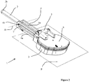
figure 5 représente une vue de trois quarts supérieure d'un système d'arme léger selon l'invention dans une dernière phase de chargement et sans trappe. - La
figure 6 représente une vue de trois quarts supérieure d'un système d'arme léger selon l'invention dans une phase de pointage et sans trappe. - La
figure 7 représente une vue latérale d'un système d'arme léger selon un deuxième mode de réalisation de l'invention dans une phase de pointage. - La
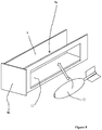
figure 8 représente une vue de trois quarts supérieure d'un moyen de chargement selon l'invention. - Selon la
figure 1 , une tourelle 100 d'un véhicule blindé (véhicule représenté très schématiquement) comporte deux trous d'homme 101 et 102 destinés à laisser entrer ou sortir tout ou partie d'un membre d'équipage dans un habitacle formé par la tourelle 100. - Chaque trou d'homme est obturé par une trappe articulée 101a et 102a. Un des trous d'homme 101 porte un système d'arme léger 1 selon l'invention, qui est destiné à tirer des obus de mortier.
- Ce système d'arme 1 comporte un tube de mortier 2 qui est, selon le mode de réalisation représenté, orienté en gisement parallèlement à l'arme principale 100a de la tourelle 100. Le pointage en gisement du système d'arme 1 sera donc effectué par la rotation de la tourelle ou du véhicule entier. Le système d'arme 1 est fixé au niveau du trou d'homme par des moyens de fixation classiques, tels que des vis et/ou boulons, d'autres moyens pourront être employés.
- Il est envisageable de solidariser le système d'arme 1 avec le véhicule dans une autre position relativement à l'axe longitudinal du véhicule ou de la tourelle. Ainsi, on pourra solidariser le système d'arme perpendiculairement à l'arme principale 100a de la tourelle par exemple.
- Selon la
figure 2 , le système d'arme comporte une rehausse 3 qui s'étend verticalement au-dessus du trou d'homme 101a (trou non visible). Cette rehausse 3 entoure toute la périphérie du trou d'homme. Un support 4 du tube de mortier 2 est solidaire de façon fixe au niveau d'une première extrémité de la rehausse 2, en-dessous d'une charnière 5 servant à l'ouverture de la trappe 6. Le support 4 s'étendant sensiblement horizontalement dans un plan d'interfaçage P du système d'arme 1 sur le trou d'homme. Le support 4 comporte à sa seconde extrémité une liaison pivot 4b destinée à permettre la rotation du tube 2 autour de l'axe horizontal A pour orienter le tube 2 en site et régler ainsi la hausse. - Selon le mode de réalisation représenté, le support 4 comporte deux flancs latéraux 4a entre lesquels une partie avant du tube 2 comportant la bouche du tube 2a peut se placer lorsqu'il est à l'horizontal.
- Le système d'arme 1 comporte un moyen d'orientation 7 du tube 2 en site. Selon le mode de réalisation représenté, le moyen d'orientation 7 est un vérin électrique solidaire d'un flanc 4a du support 4 et solidaire par une autre extrémité de la liaison pivot 4b liée au tube 2 (par exemple par un système bielle - manivelle).
- Selon un autre mode de réalisation illustré à la
figure 7 , la seconde extrémité du vérin pourra être solidaire du tube 2 directement. Ce vérin 7 est commandable depuis l'habitacle de la tourelle 100. - Le système d'arme 1 comporte un moyen de mesure (non représenté) de l'orientation en site du tube 2. De tels moyens sont bien connus de l'Homme du Métier, ils peuvent être constitués par un capteur angulaire par exemple ou tout autre moyen de mesure permettant d'indiquer la valeur de pointage en site du tube à un servant du système d'arme situé dans l'habitacle de la tourelle 100.
- Selon la
figure 3 , le système d'arme 1 est représenté sans sa trappe ni sa charnière afin de voir le fonctionnement interne du système d'arme 1. - Ainsi, on voit que la rehausse 3 comporte dans sa paroi une ouverture 8 débouchant, vers l'extérieur de la rehausse 3, entre les flancs 4a du support 4 et en regard de la bouche 2a du tube 2 lorsque celui-ci est à l'horizontale.
- Cette ouverture 8 correspond avec un moyen de chargement 9 du tube 2. Ce moyen de chargement pourra être un tiroir 9 qui est monté coulissant par une liaison glissière 10 dans l'ouverture 8, le tiroir coulissant de l'intérieur de la rehausse 3 vers l'extérieur et inversement.
- A la
figure 8 notamment, on voit que le tiroir 9 comporte sur un de ses cotés une fenêtre 11 destinée à permettre de placer un obus 12 à l'intérieur du tiroir 9. On notera que l'obus 12 est placé de manière à ce que sa partie arrière soit la plus proche de l'ouverture 8 afin que cette partie rentre par la suite la première dans la bouche 2a du tube 2 lors du chargement de l'obus 12 tel que représenté à lafigure 4 . - Lors du chargement, depuis l'habitacle de la tourelle 100, le servant a accès au tiroir tout en étant protégé par la trappe 6 qui obture la rehausse (trappe non représentée à la
figure 4 ). Il pousse le tiroir en direction du tube 2a, faisant ainsi pénétrer l'obus 12 dans la bouche du tube 2a. - Comme on le voit sur la
figure 8 , le tiroir 9 a une forme de civière et comporte donc une goulotte 9a qui est dimensionnée de façon à laisser entrer le tube 2 dans le tiroir 9 lorsqu'on pousse ce dernier pour faire coulisser l'obus 12 dans la bouche 2a du tube 2. - La goulotte 9a du tiroir 9 est par ailleurs complètement ouverte dans sa partie supérieure. Ainsi le tube peut être pivoté pour son positionnement en site sans être gêné par le tiroir 9.
- Selon la
figure 5 , une fois le tiroir 9 poussé au fond de l'ouverture 8, entre les flancs 4a du support 4, l'obus est complètement enfoncé dans la partie avant 2a du tube 2. Le tiroir 9 porte à sa partie arrière une plaque 9b (figure 8 ) formant un moyen de fermeture du fond de l'ouverture 8. Cette plaque 9b assure la protection balistique de la rehausse 3 une fois le tube basculé. Un moyen de verrouillage (non représenté) permettra de verrouiller le tiroir 9 par rapport à la rehausse 3 dans cette position. La plaque 9b sera réalisée dans un matériau ayant des capacités de résistance analogues à celle de la rehausse 3 et aura une épaisseur du même ordre que celle de la rehausse. - Le tiroir 9 est donc ouvert sur sa partie supérieure laissant le tube 2 apparent et libre de se mouvoir vers le haut.
- Selon la
figure 6 le servant commande la mise au site de tir souhaité depuis l'intérieur de la tourelle en activant le vérin 7. Le tube 2, sous l'action du moyen d'orientation 7, opère un relèvement de la bouche 2a du tube qui provoque la descente de l'obus au fond du tube 2 par gravité. - Une fois la position de site de tir souhaitée obtenue, le servant peut commander la mise à feu de l'obus par un moyen classiquement connu de l'homme du métier tel qu'un percuteur commandable à distance situé dans la culasse 2b du tube 2.
- Suivant un mode de réalisation plus simple du système d'arme selon l'invention, il est envisageable de ne pas équiper le système d'arme d'un tiroir de chargement. L'obus sera dans ce cas introduit manuellement dans la bouche du tube au travers de l'ouverture 8.
- Un volet pivotant peut être prévu pour fermer l'ouverture 8 mais l'étanchéité balistique n'est dans ce cas pas garantie pendant la phase de chargement. Cependant la faible dimension de l'ouverture 8 et sa situation protégée par les flancs 4a du support 4 offre une faible exposition du servant vis-à-vis des menaces balistiques.
- Ainsi, l'invention permet d'équiper un véhicule blindé d'un système d'arme léger pouvant être servi en sécurité depuis l'habitacle du véhicule et ceci sans faire subir de lourdes modifications au véhicule.
- On notera à la
figure 1 que la liaison pivot 4b entre le tube 2 et le support 4 est située en porte à faux par rapport à la nuque de tourelle. Ceci permet au tube 2 de pointer en hauteur sans que sa culasse ne vienne interférer avec la tourelle. Selon un autre mode de réalisation représenté à lafigure 7 , la liaison pivot 4b entre le tube 2 et le support 4 est situé en partie arrière du tube ce qui évite lors du relèvement du tube 2 d'éventuelles interférences avec des éléments du véhicule placés sous le dispositif 1.
Claims (8)
- Système d'arme (1) léger destiné à tirer des obus de mortier (12) et à s'interfacer sur un trou d'homme (101) d'un habitacle (100), système d'arme (1) comportant :- un tube (2) de mortier,- une rehausse (3) destinée à entourer le trou d'homme (101) et à s'étendre verticalement au-dessus du trou d'homme (101), rehausse (3) obturée par une trappe (6) articulée et comportant une ouverture (8) destinée à permettre d'alimenter le tube (2) de mortier par sa bouche avec un obus (12),- un support (4) du tube de mortier (2) solidaire fixement de la rehausse (3) par une première extrémité et comportant à sa seconde extrémité une liaison pivot (4b) solidaire du tube de mortier (2),- l'ouverture (8) débouchant, vers l'extérieur de la rehausse (3), entre des flancs (4a) du support (4) et en regard de la bouche (2a) du tube (2) lorsque celui-ci est à l'horizontale,- un moyen d'orientation (7) en site du tube de mortier (2),- un moyen de mise à feu (2b) destiné à déclencher le tir de l'obus (12).
- Système d'arme (1) léger selon la revendication 1, caractérisé en ce qu'il comporte un moyen de fermeture de l'ouverture (8) garantissant une protection balistique.
- Système d'arme léger selon la revendication 2, caractérisé en ce que le moyen de fermeture est solidaire d'un moyen de chargement comportant un tiroir (9) destiné à contenir un obus (12), le tiroir (9) étant monté coulissant par une liaison glissière (10) dans l'ouverture (8) de la rehausse (3).
- Système d'arme léger selon la revendication 3, caractérisé en ce que le tiroir (9) comporte une goulotte (9a) destinée à laisser passer le tube (2), le tiroir poussant lors de son coulissement l'obus (12) dans la bouche (2a) du tube (2).
- Système d'arme (1) léger selon la revendication 4, caractérisé en ce que la goulotte du tiroir (9) est ouverte dans sa partie supérieure pour laisser entrer et sortir du tiroir (9) la bouche (2a) du tube (2) durant les mouvements de positionnement en site de celui-ci.
- Système d'arme (1) léger selon une des revendications 1 à 5, caractérisé en ce qu'il comporte un capteur d'angle (20) de site destiné à donner le pointage en hausse du tube (2).
- Système d'arme (1) léger selon une des revendications 1 à 6, caractérisé en ce que le moyen de mise de feu est un percuteur commandable depuis l'intérieur du véhicule et situé dans la culasse (2b) du tube.
- Système d'arme léger selon une des revendications 1 à 7, caractérisé en ce que le moyen d'orientation (7) en site du tube est un vérin électrique (7).
Priority Applications (1)
| Application Number | Priority Date | Filing Date | Title |
|---|---|---|---|
| PL14711805T PL2956738T3 (pl) | 2013-02-12 | 2014-02-07 | System broni lekkiej |
Applications Claiming Priority (2)
| Application Number | Priority Date | Filing Date | Title |
|---|---|---|---|
| FR1300314A FR3002030B1 (fr) | 2013-02-12 | 2013-02-12 | Systeme d'arme leger |
| PCT/FR2014/050240 WO2014125195A1 (fr) | 2013-02-12 | 2014-02-07 | Systeme d'arme leger |
Publications (2)
| Publication Number | Publication Date |
|---|---|
| EP2956738A1 EP2956738A1 (fr) | 2015-12-23 |
| EP2956738B1 true EP2956738B1 (fr) | 2017-04-19 |
Family
ID=48856677
Family Applications (1)
| Application Number | Title | Priority Date | Filing Date |
|---|---|---|---|
| EP14711805.3A Active EP2956738B1 (fr) | 2013-02-12 | 2014-02-07 | Systeme d'arme leger |
Country Status (5)
| Country | Link |
|---|---|
| EP (1) | EP2956738B1 (fr) |
| FR (1) | FR3002030B1 (fr) |
| PL (1) | PL2956738T3 (fr) |
| RU (1) | RU2638203C2 (fr) |
| WO (1) | WO2014125195A1 (fr) |
Citations (21)
| Publication number | Priority date | Publication date | Assignee | Title |
|---|---|---|---|---|
| FR819842A (fr) | 1936-06-29 | 1937-10-27 | Plate-forme orientable et pivotante pour armes à feu et autres applications analogues | |
| GB772463A (en) | 1954-02-16 | 1957-04-10 | Georges Even | Armoured vehicle |
| DE2043852A1 (de) | 1969-09-04 | 1971-03-11 | Societe Nationale Industrielle Aerospatiale Paris | Versenkbare Abschußvorrichtung fur Lenkwaffen |
| EP0011856A1 (fr) | 1978-11-29 | 1980-06-11 | Industrie-Werke Karlsruhe Augsburg Aktiengesellschaft | Dispositif pour verrouiller un affût d'arme monté pivotant autour d'un axe horizontal et avec lequel une arme, p.ex. un canon à cadence de tir élevée, peut être orientée en site |
| DE3436369A1 (de) | 1984-10-04 | 1986-04-10 | Diehl GmbH & Co, 8500 Nürnberg | Waffensystem mit einer fahrzeuggebundenen vorderladerwaffe |
| EP0373283A1 (fr) | 1987-12-14 | 1990-06-20 | NORICUM MASCHINENBAU UND HANDEL GESELLSCHAFT m.b.H. | Dispositif de pointage pour système d'armes à tir plongeant mobile |
| EP0402753A2 (fr) | 1989-06-12 | 1990-12-19 | DIEHL GMBH & CO. | Arme à canon tubulaire |
| FR2674949A1 (fr) | 1991-04-04 | 1992-10-09 | Giat Ind Sa | Mortier par chargement a l'arriere. |
| EP0540848A1 (fr) | 1991-11-07 | 1993-05-12 | Wegmann & Co. GmbH | Affût à bague rotatif pour arme légère sur un véhicule blindé de combat, en particulier sur la trappe d'un char |
| DE3440467C2 (fr) | 1984-11-06 | 1993-06-03 | Diehl Gmbh & Co, 8500 Nuernberg, De | |
| FR2698438A1 (fr) | 1992-11-26 | 1994-05-27 | Bofors Ab | Mortier. |
| DE4304761A1 (de) | 1993-02-17 | 1994-08-18 | Mak System Gmbh | Waffenlafette für Panzerfahrzeuge |
| EP1273869A2 (fr) | 2001-07-07 | 2003-01-08 | Rheinmetall Landsysteme GmbH | Véhicule blindé |
| EP1318375A2 (fr) | 2001-12-07 | 2003-06-11 | Rheinmetall Landsysteme GmbH | Couvercle de trou pour un anneau de montage multifunctionel dans des véhicules blindés |
| JP2003336998A (ja) | 2002-05-21 | 2003-11-28 | Komatsu Ltd | 車両搭載式火砲発射機構 |
| EP2124011A2 (fr) | 2008-05-19 | 2009-11-25 | Alenia Aeronautica S.P.A. | Tourelle, en particulier pour véhicule blindé militaire, avec une stucture portageuse d'une arme à feu |
| DE102009009082A1 (de) | 2009-02-14 | 2010-08-19 | Krauss-Maffei Wegmann Gmbh & Co. Kg | Wirkmittelwurfsystem zum Abschuss nicht-letaler Wirkmittel von einem Fahrzeug, insbesondere einem Polizei-oder Militärfahrzeug |
| DE102007018507B4 (de) | 2007-04-19 | 2012-05-03 | Krauss-Maffei Wegmann Gmbh & Co. Kg | Verfahren und Vorrichtung zur Bekämpfung einer Angriffsmunitionskörper-Abschussvorrichtung |
| US20120167750A1 (en) | 2011-01-04 | 2012-07-05 | Lockheed Martin Corporation | Rapid fire launch system |
| DE102011050277B4 (de) | 2011-05-11 | 2012-11-29 | Krauss-Maffei Wegmann Gmbh & Co. Kg | Adapter zur Befestigung einer Lafette an einem Objekt, Lafette und militärisches Fahrzeug |
| DE102012001172A1 (de) | 2012-01-24 | 2013-07-25 | Rheinmetall Waffe Munition Gmbh | Waffe, wie Mörser oder Düsenmörser, mit Lafette |
Family Cites Families (2)
| Publication number | Priority date | Publication date | Assignee | Title |
|---|---|---|---|---|
| FR2163932A5 (fr) * | 1971-12-07 | 1973-07-27 | France Etat | |
| RU2184333C2 (ru) * | 2000-08-21 | 2002-06-27 | Открытое акционерное общество "Завод им. В.А. Дегтярева" | Башня бронемашины с системой оружия |
-
2013
- 2013-02-12 FR FR1300314A patent/FR3002030B1/fr not_active Expired - Fee Related
-
2014
- 2014-02-07 RU RU2015138764A patent/RU2638203C2/ru active
- 2014-02-07 WO PCT/FR2014/050240 patent/WO2014125195A1/fr not_active Ceased
- 2014-02-07 EP EP14711805.3A patent/EP2956738B1/fr active Active
- 2014-02-07 PL PL14711805T patent/PL2956738T3/pl unknown
Patent Citations (21)
| Publication number | Priority date | Publication date | Assignee | Title |
|---|---|---|---|---|
| FR819842A (fr) | 1936-06-29 | 1937-10-27 | Plate-forme orientable et pivotante pour armes à feu et autres applications analogues | |
| GB772463A (en) | 1954-02-16 | 1957-04-10 | Georges Even | Armoured vehicle |
| DE2043852A1 (de) | 1969-09-04 | 1971-03-11 | Societe Nationale Industrielle Aerospatiale Paris | Versenkbare Abschußvorrichtung fur Lenkwaffen |
| EP0011856A1 (fr) | 1978-11-29 | 1980-06-11 | Industrie-Werke Karlsruhe Augsburg Aktiengesellschaft | Dispositif pour verrouiller un affût d'arme monté pivotant autour d'un axe horizontal et avec lequel une arme, p.ex. un canon à cadence de tir élevée, peut être orientée en site |
| DE3436369A1 (de) | 1984-10-04 | 1986-04-10 | Diehl GmbH & Co, 8500 Nürnberg | Waffensystem mit einer fahrzeuggebundenen vorderladerwaffe |
| DE3440467C2 (fr) | 1984-11-06 | 1993-06-03 | Diehl Gmbh & Co, 8500 Nuernberg, De | |
| EP0373283A1 (fr) | 1987-12-14 | 1990-06-20 | NORICUM MASCHINENBAU UND HANDEL GESELLSCHAFT m.b.H. | Dispositif de pointage pour système d'armes à tir plongeant mobile |
| EP0402753A2 (fr) | 1989-06-12 | 1990-12-19 | DIEHL GMBH & CO. | Arme à canon tubulaire |
| FR2674949A1 (fr) | 1991-04-04 | 1992-10-09 | Giat Ind Sa | Mortier par chargement a l'arriere. |
| EP0540848A1 (fr) | 1991-11-07 | 1993-05-12 | Wegmann & Co. GmbH | Affût à bague rotatif pour arme légère sur un véhicule blindé de combat, en particulier sur la trappe d'un char |
| FR2698438A1 (fr) | 1992-11-26 | 1994-05-27 | Bofors Ab | Mortier. |
| DE4304761A1 (de) | 1993-02-17 | 1994-08-18 | Mak System Gmbh | Waffenlafette für Panzerfahrzeuge |
| EP1273869A2 (fr) | 2001-07-07 | 2003-01-08 | Rheinmetall Landsysteme GmbH | Véhicule blindé |
| EP1318375A2 (fr) | 2001-12-07 | 2003-06-11 | Rheinmetall Landsysteme GmbH | Couvercle de trou pour un anneau de montage multifunctionel dans des véhicules blindés |
| JP2003336998A (ja) | 2002-05-21 | 2003-11-28 | Komatsu Ltd | 車両搭載式火砲発射機構 |
| DE102007018507B4 (de) | 2007-04-19 | 2012-05-03 | Krauss-Maffei Wegmann Gmbh & Co. Kg | Verfahren und Vorrichtung zur Bekämpfung einer Angriffsmunitionskörper-Abschussvorrichtung |
| EP2124011A2 (fr) | 2008-05-19 | 2009-11-25 | Alenia Aeronautica S.P.A. | Tourelle, en particulier pour véhicule blindé militaire, avec une stucture portageuse d'une arme à feu |
| DE102009009082A1 (de) | 2009-02-14 | 2010-08-19 | Krauss-Maffei Wegmann Gmbh & Co. Kg | Wirkmittelwurfsystem zum Abschuss nicht-letaler Wirkmittel von einem Fahrzeug, insbesondere einem Polizei-oder Militärfahrzeug |
| US20120167750A1 (en) | 2011-01-04 | 2012-07-05 | Lockheed Martin Corporation | Rapid fire launch system |
| DE102011050277B4 (de) | 2011-05-11 | 2012-11-29 | Krauss-Maffei Wegmann Gmbh & Co. Kg | Adapter zur Befestigung einer Lafette an einem Objekt, Lafette und militärisches Fahrzeug |
| DE102012001172A1 (de) | 2012-01-24 | 2013-07-25 | Rheinmetall Waffe Munition Gmbh | Waffe, wie Mörser oder Düsenmörser, mit Lafette |
Also Published As
| Publication number | Publication date |
|---|---|
| PL2956738T3 (pl) | 2017-08-31 |
| RU2638203C2 (ru) | 2017-12-12 |
| WO2014125195A1 (fr) | 2014-08-21 |
| FR3002030B1 (fr) | 2017-08-11 |
| RU2015138764A (ru) | 2017-03-17 |
| EP2956738A1 (fr) | 2015-12-23 |
| FR3002030A1 (fr) | 2014-08-15 |
Similar Documents
| Publication | Publication Date | Title |
|---|---|---|
| US8393258B2 (en) | Retractable turret | |
| US9080828B2 (en) | Assembly of turret and low radar reflection weapon | |
| EP2071268B1 (fr) | Tourelleau escamotable | |
| FR2991763A1 (fr) | Plateau tournant motorise pour elements additionnels de tourelle. | |
| US9360266B2 (en) | Cannon and military vehicle | |
| EP2956738B1 (fr) | Systeme d'arme leger | |
| EP4042088B1 (fr) | Conteneur logistique destiné à être équipé d'au moins un moyen de protection | |
| US20130213278A1 (en) | Gun port arrangement for an armoured structure | |
| FR2950962A1 (fr) | Tourelleau de montage d'un equipement, tel un armement secondaire | |
| EP1714105B1 (fr) | Dispositif securise d'emport et de tir de cartouches telles que des cartouches de leurrage | |
| EP2163843B1 (fr) | Tourelleau escamotable | |
| FR2549218A1 (fr) | Vehicule blinde equipe d'un mortier | |
| EP3699542B1 (fr) | Véhicule furtif avec système d'arme integré à déploiement rapide | |
| FR3022338A1 (fr) | Tourelleau comportant un magasin a munitions | |
| EP2913628B1 (fr) | Fusée d'ogive de projectile d'artillerie comportant un dispositif de freinage en translation | |
| EP2437025B1 (fr) | Système d'arme lance-munition à prolongateur tubulaire | |
| IL229623A (en) | Entry pipe for firing sub-caliber ammunition bodies and weapons containing an entry pipe | |
| FR3061768A1 (fr) | Dispositif d'evacuation de douilles | |
| EP4339550A2 (fr) | Tourelle avec toit de protection escamotable | |
| FR2898968A1 (fr) | Amelioration de la protection des vehicules blindes | |
| FR3058789A1 (fr) | Systeme de tir de projectile |
Legal Events
| Date | Code | Title | Description |
|---|---|---|---|
| PUAI | Public reference made under article 153(3) epc to a published international application that has entered the european phase |
Free format text: ORIGINAL CODE: 0009012 |
|
| 17P | Request for examination filed |
Effective date: 20150911 |
|
| AK | Designated contracting states |
Kind code of ref document: A1 Designated state(s): AL AT BE BG CH CY CZ DE DK EE ES FI FR GB GR HR HU IE IS IT LI LT LU LV MC MK MT NL NO PL PT RO RS SE SI SK SM TR |
|
| AX | Request for extension of the european patent |
Extension state: BA ME |
|
| DAX | Request for extension of the european patent (deleted) | ||
| GRAP | Despatch of communication of intention to grant a patent |
Free format text: ORIGINAL CODE: EPIDOSNIGR1 |
|
| STAA | Information on the status of an ep patent application or granted ep patent |
Free format text: STATUS: GRANT OF PATENT IS INTENDED |
|
| INTG | Intention to grant announced |
Effective date: 20161129 |
|
| GRAS | Grant fee paid |
Free format text: ORIGINAL CODE: EPIDOSNIGR3 |
|
| GRAA | (expected) grant |
Free format text: ORIGINAL CODE: 0009210 |
|
| STAA | Information on the status of an ep patent application or granted ep patent |
Free format text: STATUS: THE PATENT HAS BEEN GRANTED |
|
| AK | Designated contracting states |
Kind code of ref document: B1 Designated state(s): AL AT BE BG CH CY CZ DE DK EE ES FI FR GB GR HR HU IE IS IT LI LT LU LV MC MK MT NL NO PL PT RO RS SE SI SK SM TR |
|
| REG | Reference to a national code |
Ref country code: GB Ref legal event code: FG4D Free format text: NOT ENGLISH |
|
| REG | Reference to a national code |
Ref country code: CH Ref legal event code: EP |
|
| REG | Reference to a national code |
Ref country code: AT Ref legal event code: REF Ref document number: 886397 Country of ref document: AT Kind code of ref document: T Effective date: 20170515 |
|
| REG | Reference to a national code |
Ref country code: IE Ref legal event code: FG4D Free format text: LANGUAGE OF EP DOCUMENT: FRENCH |
|
| REG | Reference to a national code |
Ref country code: DE Ref legal event code: R096 Ref document number: 602014008780 Country of ref document: DE |
|
| REG | Reference to a national code |
Ref country code: SE Ref legal event code: TRGR |
|
| REG | Reference to a national code |
Ref country code: NL Ref legal event code: MP Effective date: 20170419 |
|
| REG | Reference to a national code |
Ref country code: NO Ref legal event code: T2 Effective date: 20170419 |
|
| REG | Reference to a national code |
Ref country code: LT Ref legal event code: MG4D |
|
| REG | Reference to a national code |
Ref country code: AT Ref legal event code: MK05 Ref document number: 886397 Country of ref document: AT Kind code of ref document: T Effective date: 20170419 |
|
| PG25 | Lapsed in a contracting state [announced via postgrant information from national office to epo] |
Ref country code: NL Free format text: LAPSE BECAUSE OF FAILURE TO SUBMIT A TRANSLATION OF THE DESCRIPTION OR TO PAY THE FEE WITHIN THE PRESCRIBED TIME-LIMIT Effective date: 20170419 |
|
| PG25 | Lapsed in a contracting state [announced via postgrant information from national office to epo] |
Ref country code: ES Free format text: LAPSE BECAUSE OF FAILURE TO SUBMIT A TRANSLATION OF THE DESCRIPTION OR TO PAY THE FEE WITHIN THE PRESCRIBED TIME-LIMIT Effective date: 20170419 Ref country code: AT Free format text: LAPSE BECAUSE OF FAILURE TO SUBMIT A TRANSLATION OF THE DESCRIPTION OR TO PAY THE FEE WITHIN THE PRESCRIBED TIME-LIMIT Effective date: 20170419 Ref country code: GR Free format text: LAPSE BECAUSE OF FAILURE TO SUBMIT A TRANSLATION OF THE DESCRIPTION OR TO PAY THE FEE WITHIN THE PRESCRIBED TIME-LIMIT Effective date: 20170720 Ref country code: HR Free format text: LAPSE BECAUSE OF FAILURE TO SUBMIT A TRANSLATION OF THE DESCRIPTION OR TO PAY THE FEE WITHIN THE PRESCRIBED TIME-LIMIT Effective date: 20170419 Ref country code: LT Free format text: LAPSE BECAUSE OF FAILURE TO SUBMIT A TRANSLATION OF THE DESCRIPTION OR TO PAY THE FEE WITHIN THE PRESCRIBED TIME-LIMIT Effective date: 20170419 |
|
| PG25 | Lapsed in a contracting state [announced via postgrant information from national office to epo] |
Ref country code: BG Free format text: LAPSE BECAUSE OF FAILURE TO SUBMIT A TRANSLATION OF THE DESCRIPTION OR TO PAY THE FEE WITHIN THE PRESCRIBED TIME-LIMIT Effective date: 20170719 Ref country code: LV Free format text: LAPSE BECAUSE OF FAILURE TO SUBMIT A TRANSLATION OF THE DESCRIPTION OR TO PAY THE FEE WITHIN THE PRESCRIBED TIME-LIMIT Effective date: 20170419 Ref country code: IS Free format text: LAPSE BECAUSE OF FAILURE TO SUBMIT A TRANSLATION OF THE DESCRIPTION OR TO PAY THE FEE WITHIN THE PRESCRIBED TIME-LIMIT Effective date: 20170819 Ref country code: RS Free format text: LAPSE BECAUSE OF FAILURE TO SUBMIT A TRANSLATION OF THE DESCRIPTION OR TO PAY THE FEE WITHIN THE PRESCRIBED TIME-LIMIT Effective date: 20170419 |
|
| REG | Reference to a national code |
Ref country code: DE Ref legal event code: R026 Ref document number: 602014008780 Country of ref document: DE |
|
| REG | Reference to a national code |
Ref country code: FR Ref legal event code: PLFP Year of fee payment: 5 |
|
| PLBI | Opposition filed |
Free format text: ORIGINAL CODE: 0009260 |
|
| PG25 | Lapsed in a contracting state [announced via postgrant information from national office to epo] |
Ref country code: CZ Free format text: LAPSE BECAUSE OF FAILURE TO SUBMIT A TRANSLATION OF THE DESCRIPTION OR TO PAY THE FEE WITHIN THE PRESCRIBED TIME-LIMIT Effective date: 20170419 Ref country code: RO Free format text: LAPSE BECAUSE OF FAILURE TO SUBMIT A TRANSLATION OF THE DESCRIPTION OR TO PAY THE FEE WITHIN THE PRESCRIBED TIME-LIMIT Effective date: 20170419 Ref country code: DK Free format text: LAPSE BECAUSE OF FAILURE TO SUBMIT A TRANSLATION OF THE DESCRIPTION OR TO PAY THE FEE WITHIN THE PRESCRIBED TIME-LIMIT Effective date: 20170419 Ref country code: EE Free format text: LAPSE BECAUSE OF FAILURE TO SUBMIT A TRANSLATION OF THE DESCRIPTION OR TO PAY THE FEE WITHIN THE PRESCRIBED TIME-LIMIT Effective date: 20170419 Ref country code: SK Free format text: LAPSE BECAUSE OF FAILURE TO SUBMIT A TRANSLATION OF THE DESCRIPTION OR TO PAY THE FEE WITHIN THE PRESCRIBED TIME-LIMIT Effective date: 20170419 |
|
| PLAX | Notice of opposition and request to file observation + time limit sent |
Free format text: ORIGINAL CODE: EPIDOSNOBS2 |
|
| 26 | Opposition filed |
Opponent name: RHEINMETALL WAFFE MUNITION GMBH Effective date: 20180119 |
|
| PG25 | Lapsed in a contracting state [announced via postgrant information from national office to epo] |
Ref country code: SM Free format text: LAPSE BECAUSE OF FAILURE TO SUBMIT A TRANSLATION OF THE DESCRIPTION OR TO PAY THE FEE WITHIN THE PRESCRIBED TIME-LIMIT Effective date: 20170419 |
|
| PG25 | Lapsed in a contracting state [announced via postgrant information from national office to epo] |
Ref country code: SI Free format text: LAPSE BECAUSE OF FAILURE TO SUBMIT A TRANSLATION OF THE DESCRIPTION OR TO PAY THE FEE WITHIN THE PRESCRIBED TIME-LIMIT Effective date: 20170419 |
|
| PLBB | Reply of patent proprietor to notice(s) of opposition received |
Free format text: ORIGINAL CODE: EPIDOSNOBS3 |
|
| REG | Reference to a national code |
Ref country code: CH Ref legal event code: PL |
|
| PG25 | Lapsed in a contracting state [announced via postgrant information from national office to epo] |
Ref country code: MC Free format text: LAPSE BECAUSE OF FAILURE TO SUBMIT A TRANSLATION OF THE DESCRIPTION OR TO PAY THE FEE WITHIN THE PRESCRIBED TIME-LIMIT Effective date: 20170419 Ref country code: MT Free format text: LAPSE BECAUSE OF FAILURE TO SUBMIT A TRANSLATION OF THE DESCRIPTION OR TO PAY THE FEE WITHIN THE PRESCRIBED TIME-LIMIT Effective date: 20170419 |
|
| REG | Reference to a national code |
Ref country code: IE Ref legal event code: MM4A |
|
| REG | Reference to a national code |
Ref country code: BE Ref legal event code: MM Effective date: 20180228 |
|
| PG25 | Lapsed in a contracting state [announced via postgrant information from national office to epo] |
Ref country code: CH Free format text: LAPSE BECAUSE OF NON-PAYMENT OF DUE FEES Effective date: 20180228 Ref country code: LU Free format text: LAPSE BECAUSE OF NON-PAYMENT OF DUE FEES Effective date: 20180207 Ref country code: LI Free format text: LAPSE BECAUSE OF NON-PAYMENT OF DUE FEES Effective date: 20180228 |
|
| PG25 | Lapsed in a contracting state [announced via postgrant information from national office to epo] |
Ref country code: IE Free format text: LAPSE BECAUSE OF NON-PAYMENT OF DUE FEES Effective date: 20180207 |
|
| PG25 | Lapsed in a contracting state [announced via postgrant information from national office to epo] |
Ref country code: BE Free format text: LAPSE BECAUSE OF NON-PAYMENT OF DUE FEES Effective date: 20180228 |
|
| REG | Reference to a national code |
Ref country code: DE Ref legal event code: R100 Ref document number: 602014008780 Country of ref document: DE |
|
| PLCK | Communication despatched that opposition was rejected |
Free format text: ORIGINAL CODE: EPIDOSNREJ1 |
|
| PLBN | Opposition rejected |
Free format text: ORIGINAL CODE: 0009273 |
|
| STAA | Information on the status of an ep patent application or granted ep patent |
Free format text: STATUS: OPPOSITION REJECTED |
|
| 27O | Opposition rejected |
Effective date: 20190626 |
|
| PG25 | Lapsed in a contracting state [announced via postgrant information from national office to epo] |
Ref country code: PT Free format text: LAPSE BECAUSE OF FAILURE TO SUBMIT A TRANSLATION OF THE DESCRIPTION OR TO PAY THE FEE WITHIN THE PRESCRIBED TIME-LIMIT Effective date: 20170419 |
|
| PG25 | Lapsed in a contracting state [announced via postgrant information from national office to epo] |
Ref country code: HU Free format text: LAPSE BECAUSE OF FAILURE TO SUBMIT A TRANSLATION OF THE DESCRIPTION OR TO PAY THE FEE WITHIN THE PRESCRIBED TIME-LIMIT; INVALID AB INITIO Effective date: 20140207 Ref country code: MK Free format text: LAPSE BECAUSE OF NON-PAYMENT OF DUE FEES Effective date: 20170419 Ref country code: CY Free format text: LAPSE BECAUSE OF FAILURE TO SUBMIT A TRANSLATION OF THE DESCRIPTION OR TO PAY THE FEE WITHIN THE PRESCRIBED TIME-LIMIT Effective date: 20170419 |
|
| PG25 | Lapsed in a contracting state [announced via postgrant information from national office to epo] |
Ref country code: AL Free format text: LAPSE BECAUSE OF FAILURE TO SUBMIT A TRANSLATION OF THE DESCRIPTION OR TO PAY THE FEE WITHIN THE PRESCRIBED TIME-LIMIT Effective date: 20170419 |
|
| PGFP | Annual fee paid to national office [announced via postgrant information from national office to epo] |
Ref country code: PL Payment date: 20250122 Year of fee payment: 12 |
|
| PGFP | Annual fee paid to national office [announced via postgrant information from national office to epo] |
Ref country code: SE Payment date: 20260121 Year of fee payment: 13 |
|
| PGFP | Annual fee paid to national office [announced via postgrant information from national office to epo] |
Ref country code: GB Payment date: 20260121 Year of fee payment: 13 |
|
| PGFP | Annual fee paid to national office [announced via postgrant information from national office to epo] |
Ref country code: NO Payment date: 20260123 Year of fee payment: 13 Ref country code: DE Payment date: 20260121 Year of fee payment: 13 |
|
| PGFP | Annual fee paid to national office [announced via postgrant information from national office to epo] |
Ref country code: IT Payment date: 20260121 Year of fee payment: 13 Ref country code: FI Payment date: 20260121 Year of fee payment: 13 |
|
| PGFP | Annual fee paid to national office [announced via postgrant information from national office to epo] |
Ref country code: FR Payment date: 20260121 Year of fee payment: 13 |
|
| PGFP | Annual fee paid to national office [announced via postgrant information from national office to epo] |
Ref country code: TR Payment date: 20260126 Year of fee payment: 13 |