EP2306282A2 - Sensorvorrichtung und Informationsverarbeitungsvorrichtung - Google Patents
Sensorvorrichtung und Informationsverarbeitungsvorrichtung Download PDFInfo
- Publication number
- EP2306282A2 EP2306282A2 EP10172764A EP10172764A EP2306282A2 EP 2306282 A2 EP2306282 A2 EP 2306282A2 EP 10172764 A EP10172764 A EP 10172764A EP 10172764 A EP10172764 A EP 10172764A EP 2306282 A2 EP2306282 A2 EP 2306282A2
- Authority
- EP
- European Patent Office
- Prior art keywords
- pressure
- sensitive sensor
- sensor
- sensor device
- barrier
- Prior art date
- Legal status (The legal status is an assumption and is not a legal conclusion. Google has not performed a legal analysis and makes no representation as to the accuracy of the status listed.)
- Withdrawn
Links
Images





Classifications
-
- H—ELECTRICITY
- H01—ELECTRIC ELEMENTS
- H01G—CAPACITORS; CAPACITORS, RECTIFIERS, DETECTORS, SWITCHING DEVICES, LIGHT-SENSITIVE OR TEMPERATURE-SENSITIVE DEVICES OF THE ELECTROLYTIC TYPE
- H01G5/00—Capacitors in which the capacitance is varied by mechanical means, e.g. by turning a shaft; Processes of their manufacture
- H01G5/16—Capacitors in which the capacitance is varied by mechanical means, e.g. by turning a shaft; Processes of their manufacture using variation of distance between electrodes
-
- G—PHYSICS
- G06—COMPUTING OR CALCULATING; COUNTING
- G06F—ELECTRIC DIGITAL DATA PROCESSING
- G06F3/00—Input arrangements for transferring data to be processed into a form capable of being handled by the computer; Output arrangements for transferring data from processing unit to output unit, e.g. interface arrangements
- G06F3/01—Input arrangements or combined input and output arrangements for interaction between user and computer
- G06F3/017—Gesture based interaction, e.g. based on a set of recognized hand gestures
-
- G—PHYSICS
- G06—COMPUTING OR CALCULATING; COUNTING
- G06F—ELECTRIC DIGITAL DATA PROCESSING
- G06F3/00—Input arrangements for transferring data to be processed into a form capable of being handled by the computer; Output arrangements for transferring data from processing unit to output unit, e.g. interface arrangements
- G06F3/01—Input arrangements or combined input and output arrangements for interaction between user and computer
- G06F3/03—Arrangements for converting the position or the displacement of a member into a coded form
- G06F3/033—Pointing devices displaced or positioned by the user, e.g. mice, trackballs, pens or joysticks; Accessories therefor
- G06F3/0354—Pointing devices displaced or positioned by the user, e.g. mice, trackballs, pens or joysticks; Accessories therefor with detection of two-dimensional [2D] relative movements between the device, or an operating part thereof, and a plane or surface, e.g. 2D mice, trackballs, pens or pucks
- G06F3/03545—Pens or stylus
-
- G—PHYSICS
- G06—COMPUTING OR CALCULATING; COUNTING
- G06F—ELECTRIC DIGITAL DATA PROCESSING
- G06F3/00—Input arrangements for transferring data to be processed into a form capable of being handled by the computer; Output arrangements for transferring data from processing unit to output unit, e.g. interface arrangements
- G06F3/01—Input arrangements or combined input and output arrangements for interaction between user and computer
- G06F3/03—Arrangements for converting the position or the displacement of a member into a coded form
- G06F3/041—Digitisers, e.g. for touch screens or touch pads, characterised by the transducing means
- G06F3/044—Digitisers, e.g. for touch screens or touch pads, characterised by the transducing means by capacitive means
- G06F3/0445—Digitisers, e.g. for touch screens or touch pads, characterised by the transducing means by capacitive means using two or more layers of sensing electrodes, e.g. using two layers of electrodes separated by a dielectric layer
-
- G—PHYSICS
- G06—COMPUTING OR CALCULATING; COUNTING
- G06F—ELECTRIC DIGITAL DATA PROCESSING
- G06F3/00—Input arrangements for transferring data to be processed into a form capable of being handled by the computer; Output arrangements for transferring data from processing unit to output unit, e.g. interface arrangements
- G06F3/01—Input arrangements or combined input and output arrangements for interaction between user and computer
- G06F3/03—Arrangements for converting the position or the displacement of a member into a coded form
- G06F3/041—Digitisers, e.g. for touch screens or touch pads, characterised by the transducing means
- G06F3/044—Digitisers, e.g. for touch screens or touch pads, characterised by the transducing means by capacitive means
- G06F3/0447—Position sensing using the local deformation of sensor cells
-
- G—PHYSICS
- G06—COMPUTING OR CALCULATING; COUNTING
- G06F—ELECTRIC DIGITAL DATA PROCESSING
- G06F2203/00—Indexing scheme relating to G06F3/00 - G06F3/048
- G06F2203/041—Indexing scheme relating to G06F3/041 - G06F3/045
- G06F2203/04105—Pressure sensors for measuring the pressure or force exerted on the touch surface without providing the touch position
-
- G—PHYSICS
- G06—COMPUTING OR CALCULATING; COUNTING
- G06F—ELECTRIC DIGITAL DATA PROCESSING
- G06F2203/00—Indexing scheme relating to G06F3/00 - G06F3/048
- G06F2203/041—Indexing scheme relating to G06F3/041 - G06F3/045
- G06F2203/04107—Shielding in digitiser, i.e. guard or shielding arrangements, mostly for capacitive touchscreens, e.g. driven shields, driven grounds
-
- H—ELECTRICITY
- H03—ELECTRONIC CIRCUITRY
- H03K—PULSE TECHNIQUE
- H03K2217/00—Indexing scheme related to electronic switching or gating, i.e. not by contact-making or -breaking covered by H03K17/00
- H03K2217/94—Indexing scheme related to electronic switching or gating, i.e. not by contact-making or -breaking covered by H03K17/00 characterised by the way in which the control signal is generated
- H03K2217/96—Touch switches
- H03K2217/9607—Capacitive touch switches
- H03K2217/960755—Constructional details of capacitive touch and proximity switches
- H03K2217/960765—Details of shielding arrangements
Definitions
- the present invention relates to a sensor device and an information processing device.
- information processing devices such as mobile phones and car navigation systems each of which includes a sensor device including a touch panel have been distributed in the market.
- a variety of methods such as a resistive method, an electromagnetic method, and a capacitive method are adopted. According to such technology, by the contact of an operation tool such as a finger or a touch pen on the touch panel, the position of the operation tool can be detected.
- the touch panel described above is for detecting the position of an operation tool, the pressure on the touch panel is difficult to be determined, which thus limits realizable operation.
- information processing devices each of which is provided with a pressure-sensitive sensor for changing the capacitance according to pressure on a touch panel. According to the device, change in the pressure exerted on the touch panel by a user is detected as change in the capacitance of the pressure-sensitive sensor, and thereby a variety of operation according to the change in pressure (pressing force) in addition to the position can be realized.
- the capacitance to be detected may change based on capacitive coupling between the pressure-sensitive sensor and the operation tool even by the approach of an operation tool such as a finger of the user.
- the change in the capacitance value is false detection, so that the pressure-sensitive sensor outputs a false pressure value.
- a sensor device and an information processing device which are novel and improved, and which are capable of preventing change in the capacitance of the sensor device due to capacitive coupling with an operation tool that occurs with approach of the operation tool such as a finger.
- a sensor device including a pressure-sensitive sensor which changes shape in response to pressing of an operation tool, such as a user's finger, and which detects changes in capacitance due to the change in shape, and a barrier which covers at least a part of the pressure-sensitive sensor and which inhibits or prevents changes in capacitance of the pressure-sensitive sensor due to capacitive coupling that occurs with approach between the pressure-sensitive sensor and the operation tool.
- the barrier may be an electric conductor connected to a ground, and the electric conductor may inhibit or prevent the change in the capacitance of the pressure-sensitive sensor due to the capacitive coupling between the operation tool and the pressure-sensitive sensor.
- a touch panel which includes an input operation surface and which detects a pressing position of the operation tool on the input operation surface.
- the pressure-sensitive sensor may change form according to the pressing position on the input operation surface of the touch panel, and the pressure-sensitive sensor may detect the change in the capacitance due to the change in shape while inhibiting or preventing false detection of the pressure-sensitive sensor due to the operation tool near the pressure-sensitive sensor by using the barrier.
- the barrier may cover the pressure-sensitive sensor from the input operation surface side and from a surface side perpendicular to the input operation surface.
- the barrier may include a first barrier which covers the pressure-sensitive sensor from the input operation surface side and a second barrier which covers the pressure-sensitive sensor from the surface side perpendicular to the input operation surface, the first barrier and the second barrier may be physically separated, and the first barrier may be movable according to the change in form.
- the first barrier may be a thin film.
- the second barrier may cover, among surfaces of the pressure-sensitive sensor, a surface on the opposite side of the touch panel side.
- the second barrier may be formed with a distal end higher than a position of the input operation surface.
- the pressure-sensitive sensor may include a first elastic body
- the barrier may include a second elastic body which changes form with the first elastic body while being integrated with the first elastic body, according to the pressing of the operation tool.
- an information processing device including a pressure-sensitive sensor which changes shape in response to pressing of an operation tool and which detects change in capacitance due to the change in shape, a barrier which covers at least a part of the pressure-sensitive sensor and which inhibits or prevents changes in capacitance of the pressure-sensitive sensor due to capacitive coupling that occurs with approach between the pressure-sensitive sensor and the operation tool, and a controller which processes information according to operation of the operation tool based on the changes in the capacitance detected by the pressure-sensitive sensor.
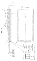
- FIGS. 8 and FIGS. 9 are sectional views and a plan view of the sensor device 10 according to the related art.
- FIGS. 9 are sectional views of the sensor device 10 according to the related art to which fingers 50, 52, and 54 are in proximity.
- an X direction shown in FIGS. 8 and FIGS. 9 refers to a direction perpendicular to the thickness direction in which a pressure-sensitive sensor 11, a touch panel 12, and a top plate 15 are stacked on a base member 16.
- a Y direction shown in FIGS. 8 and FIGS. 9 refers to a direction perpendicular to the thickness direction in which the pressure-sensitive sensor 11, the touch panel 12, and the top plate 15 are stacked on the base member 16 and orthogonal to the X direction.
- a Z direction shown in FIGS. 8 and FIGS. 9 refers to a direction perpendicular to X-Y plane. Note that an X direction, a Y direction, and a Z direction in FIG. 2 to FIG. 7 described below are the same as the X direction, the Y direction, and the Z direction shown in FIGS. 8 and FIGS. 9 .
- an operation tool such as a finger or a stylus and a metal object can be given as examples of objects which cause capacitive coupling with a pressure-sensitive sensor
- the description in the following will be made mainly taking the fingers 50, 52, and 54 as examples.
- FIG. 8 (a) is a sectional view showing a cross-section of the sensor device 10 taken along the cross-section line 3-3 in FIG. 8 (b) .
- FIG. 8 (b) is a plan view of the surface of the sensor device 10 seen from the positive Z-axis direction.
- FIG. 8 (c) is an enlarged sectional view of the pressure-sensitive sensor 11 in FIG. 8 (a) .
- the sensor device 10 includes the base member 16, the pressure-sensitive sensor 11, the capacitive touch panel 12, and the top plate 15.
- the pressure-sensitive sensor 11 is arranged on the base member 16. As shown in FIG. 8 (b) , the pressure-sensitive sensor 11 is formed with a substantially rectangular frame. Moreover, as shown in FIG. 8 (c) , the pressure-sensitive sensor 11 includes two electrodes 22 and an elastic body 24. The elastic body 24 is sandwiched between the two electrodes 22 aligned in the Z direction. The elastic body 24 contracts by the pressure of an operation tool such as the finger 50 in the negative direction of the Z-axis. The pressure-sensitive sensor 11 detects change in capacitance caused by the elastic body 24 contracting and the distance between the two electrodes 22 being changed, as change in electric current or voltage. Examples of the elastic body 24 include a rubber elastic body and a sponge. Examples of rubber materials include a urethane rubber and a silicone rubber.
- the touch panel 12 is formed immediately above the pressure-sensitive sensor 11.
- the touch panel 12 is a capacitive type with the surface which the finger 50 contacts served as an input operation surface, and the touch panel 12 detects change in the capacitance of an electrode formed on the input operation surface by contact of the finger 50 on the input operation surface, thereby detecting a position of the finger 50 in the XY direction.
- a display panel (not shown) is formed between the touch panel 12 and the base member 16. A user brings the finger 50 in contact with a predetermined position on the XY surface according to the content displayed on the display panel.
- the touch panel 12 includes, for example, a polyimide substrate, a PET film substrate, or a glass substrate.
- the top plate 15 is formed on the touch panel 12.
- the top plate 15 plays a function of protecting the touch panel 12 and prevents occurrence of scratch on the touch panel 12.
- the finger 50 presses the touch panel 12 via the top plate 15.
- the top plate 15 includes a glass substrate or a resin substrate, for example.
- the controller 17 is connected to the pressure-sensitive sensor 11 and the touch panel 12.
- the controller 17 controls a predetermined input operation of a mobile device provided with the sensor device 10, according to the detection values of the pressure-sensitive sensor 11 and the touch panel 12.
- the controller 17 calculates the pressure of the operation tool based on the capacitance detected by the pressure-sensitive sensor 11.
- FIG. 9 (a) shows the sensor device 10 with the fingers 50, 52, and 54 in proximity thereto.
- FIG. 9 (b) shows the sensor 10 with the fingers 50, 52, and 54 not yet in proximity thereto.
- FIG. 9 (c) is an enlarged sectional view of the sensor device 10 with the finger 50 in proximity thereto.
- Change in the capacitance of the pressure-sensitive sensor 11 is caused by the finger 50 approaching the sensor device 10. This is because the proximity of the finger 50 to the sensor device 10 causes capacitive coupling between the finger 50 and the sensor device 10 (electrode of the pressure-sensitive sensor 11), which makes a difference to the capacitance of the pressure-sensitive sensor 11.
- the cause of the change in the capacitance of the pressure-sensitive sensor 11 is not limited to the proximity of the finger from the above. For example, as shown in FIG. 9(a) , the capacitance of the pressure-sensitive sensor 11 changes also in the case where the finger 52 approaches from the side of the sensor device 10 or in the case where the finger 54 approaches from below the sensor device 10.
- the pressure-sensitive sensor 11 may falsely detect change in the capacitance which does not reflect the pressure desired to be detected. Consequently, in the following, there will be described a sensor device according to the present embodiment which prevents change in capacitance caused by proximity of a finger in order to detect change in the capacitance with high accuracy.
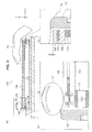
- FIG. 1 is a diagram for explaining the mobile phone 1000 provided with the sensor device according to the embodiments.
- the mobile phone 1000 shown in FIG. 1 is formed by using a sensor device 100 (which may be a sensor device 200 or a sensor device 300; the same applies to descriptions made with reference to FIG. 1 , hereinafter).
- the sensor device 100 mainly includes a pressure-sensitive sensor 110 and a touch panel 120.
- a user brings a finger 50 into contact with the touch panel 120 and presses the touch panel 120 with the finger, thereby performing input operation to the mobile phone 1000.
- a position of the finger 50 is detected by the touch panel 120.
- the pressure-sensitive sensor 110 detects change in capacitance based on change in the distance between two electrodes caused by contraction of an elastic body sandwiched by the two electrodes, as a pressure of the finger 50. In this manner, input operation is controlled in the mobile phone 1000 according to the contact position of the finger 50 on the touch panel 120 and the pressure of the finger 50.
- the mobile phone 1000 is given as an example of the information processing device provided with the sensor device 100
- use of the sensor device 100 is not particularly limited, and the sensor device 100 can be applied to a variety of devices such as portable communication devices including PHS (Personal Handyphone System) cellular phones, portable video/music players, portable game players, and computers including PDAs (Personal Digital Assistants) and notebook PCs. Note that there may be a case where the sensor device 100 is not provided with the touch panel 120.
- PHS Personal Handyphone System
- portable video/music players Portable video/music players
- portable game players portable game players
- computers including PDAs (Personal Digital Assistants) and notebook PCs.
- notebook PCs Personal Computers
- FIGS. 2 are a sectional view and a plan view for explaining the sensor device according to the first embodiment of the present invention.
- FIGS. 3 are sectional views of the sensor device according to the embodiment to which fingers are in proximity.
- the sensor device is provided to a mobile device, for example.
- FIG. 2 (a) is a sectional view showing a cross-section of the sensor device 100 taken along the cross-section line 1-1 in FIG. 2 (b) .
- FIG. 2 (b) is a plan view of the surface of the sensor device 100 seen from the positive Z-axis direction.
- FIG. 2 (c) is an enlarged sectional view of the pressure-sensitive sensor 110 in FIG. 2 (a) .
- the sensor device 100 includes a base member 160, a pressure-sensitive sensor 110, a capacitive touch panel 120, a top plate 150, a conductive housing 130, and a conductive evaporated film 140.
- the pressure-sensitive sensor 110 includes two electrodes 112 and an elastic body 114.
- the sensor device 100 is installed on the base member 160.
- a mobile phone 1000 provided with the sensor device 100 is often placed on a table 60 in FIG. 3 or the like.
- the base member 160 is formed of a resin substrate, for example.
- the conductive housing 130 is formed of a conductive material and is formed of a barrier and the like.
- the conductive housing 130 is a metal housing having a groove running through the center adapted to fit the external shape of the touch panel 120.
- the conductive housing 130 is fitted into the base member 160.
- the conductive housing 130 prevents occurrence of capacitive coupling between a finger approaching from the side of the sensor device 100 and the pressure-sensitive sensor 110.
- Projection 132 is formed on the conductive housing 130.
- the projection 132 protrudes from the XY surface and plays a role of supporting the pressure-sensitive sensor 110, the touch panel 120, the conductive evaporated film 140, and the top plate 150.
- the projection 132 prevents occurrence of capacitive coupling between a finger and the pressure-sensitive sensor 110 against the finger's approach to the sensor device 100 from the negative direction of the Z axis (from the bottom side).
- the conductive housing 130 is connected to a ground in order to prevent occurrence of capacitive coupling between a finger and the pressure-sensitive sensor 110. It is only necessary for the conductive housing 130 to be a conductive material, which contains as the main component aluminum, conductive rubber, or conductive carbon, for example.
- a thin film metal surface is formed on the bottom surface of the top plate 150 by evaporation. Moreover, as shown in FIG. 2 (b) , by making the conductive evaporated film 140 in the form of a frame, the top surface of the pressure-sensitive sensor 110 is covered by the conductive evaporated film 140. Moreover, the conductive evaporated film 140 does not exist anywhere other than the outer edge of the touch panel 120, which thus does not affect position detection of the touch panel 120.
- the conductive evaporated film 140 is formed of a conductive material and is an example of the barrier.
- the conductive evaporated film 140 is formed on the pressure-sensitive sensor 110 as shown in FIG. 2 (a) , and the pressure-sensitive sensor 110, the touch panel 120, and the conductive evaporated film 140 are formed in that order.
- the pressure-sensitive sensor 110, the conductive evaporated film 140, and the touch panel 120 may be formed in that order.
- the conductive evaporated film 140 is not physically attached to the conductive housing 130. This enables the conductive evaporated film 140 to move up and down with the top plate 150 and the touch panel 120. Consequently, by a finger 50 pressing the touch panel 120, the pressure-sensitive sensor 110 contracts.
- the conductive evaporated film 140 is connected to the ground in order to prevent occurrence of capacitive coupling between the pressure-sensitive sensor 110 and the finger 50.
- the conductive evaporated film 140 contains as the main component aluminum, conductive rubber, or conductive carbon, for example.
- the conductive evaporated film 140 may include as the main component the same material as the conductive housing 130 or may include as the main component a different material from the conductive housing 130.
- the pressure-sensitive sensor 110 is a substantially-rectangular frame.
- the elastic body 114 changes shape (contracts) by pressure exerted on the top plate 150 (the touch panel 120) due to finger's pressing.
- the distance between the two electrodes 112 is changed by the elastic body 114 shown in FIG. 2 (c) contracting, and thereby the capacitance between the electrodes changes.
- the capacitance of the pressure-sensitive sensor 110 is transmitted to a controller 170.
- the elastic body 114 include a rubber elastic body and a sponge.
- rubber materials include a urethane rubber and a silicone rubber.
- An insulator 116 is formed on the surface of the electrode.
- An example of the insulator 116 is double-sided tape.
- the touch panel 120 is formed immediately above the pressure-sensitive sensor 110.
- the touch panel 120 is a capacitive type including an input operation surface on the surface which the finger contacts.
- the input operation surface detects the contact position of the finger on the XY surface.
- a display panel (not shown) is formed between the touch panel 120 and the base member 160. A user causes the finger to contact and press a predetermined position of the touch panel 120 according to the content displayed on the display panel.
- the touch panel 120 includes, for example, a polyimide substrate, a PET film substrate, or a glass substrate.
- the top plate 150 is formed on the touch panel 120.
- the top plate 150 plays a function of protecting the touch panel 120 and prevents occurrence of scratch on the touch panel 120.
- the finger presses the touch panel 120 via the top plate 150.
- the top plate 150 includes a glass substrate or a resin substrate, for example.
- the controller 170 is connected to the pressure-sensitive sensor 110 and the touch panel 120.
- the controller 170 calculates the value of the pressure of the finger's pressing from the change amount of the capacitance detected by the pressure-sensitive sensor 110 and calculates the contact position from the change amount of the capacitance detected by the touch panel 120.
- FIGS. 3 a state where a finger is in proximity to the sensor device 100 will be described with reference to FIGS. 3 .
- capacitive coupling is about to occur between the finger 50 and the pressure-sensitive sensor 110 as shown in the enlarged view of FIG. 3 (b) .
- the conductive evaporated film 140 between the finger 50 and the pressure-sensitive sensor 110, and the conductive evaporated film 140 is connected to the ground, as describe above. Consequently, the conductive evaporated film 140 prevents occurrence of capacitive coupling between the pressure-sensitive sensor 110 and the finger 50.
- the projection 132 of the conductive housing 130 between the metal table 60 or the finger and the pressure-sensitive sensor 110 there is the projection 132 of the conductive housing 130 between the metal table 60 or the finger and the pressure-sensitive sensor 110, and the conductive housing 130 is connected to the ground. Consequently, the projection 132 prevents occurrence of capacitive coupling between the pressure-sensitive sensor 110 and the metal table 60 or the finger. As a result, the pressure-sensitive sensor 110 can detect change in the capacitance with high accuracy.
- control of input operation according to pressing by the fingers 50 and 52 performed by the sensor device 100 can be realized by providing the conductive housing 130 and the conductive evaporated film 140.
- provision of the projection 132 prevents occurrence of capacitive coupling between the pressure-sensitive sensor 110 and the metal table 60 or the finger, so that thinning of the device can be realized without worrying about the capacitive coupling.
- the sensor device 100 can prevent occurrence of capacitive coupling between the finger and the pressure-sensitive sensor 110. Furthermore, in the configuration of the device shown in FIG. 3 , it never happens that a finger or the like approaches the inside of the sensor device 100, but approach to the inside is possible depending on a configuration of the sensor device 100. In this case, a metal surface connected a ground in the same manner is placed around the inner surface of a pressure-sensitive sensor 110, and thereby false detection of a pressure value can be prevented.
- the pressure value is desirable to be zero.
- the hand contacts the side of a top plate 150 in FIG. 1 on B part, which affects the sensor value of a pressure-sensitive sensor 110.
- the heights of the distal portions of the conductive housing 130 are set only dt (>0) higher than the top surface of the top plate as shown in FIG. 3 (c) , and thereby, in the operation as shown in FIG.
- occurrence of capacitive coupling between the hand on B part and the pressure-sensitive sensor 110 can be prevented by the conductive housing 130.
- the conductive housing 130 functions as a barrier to make the finger 52 physically difficult to approach the pressure-sensitive sensor 110, which thus can prevent false detection of a pressure value.
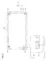
- FIG. 4 is a plan view of the surface of the sensor device 105 seen from the positive Z-axis direction.
- the sensor device 105 includes a base member 160, pressure-sensitive sensors 115, a touch panel 120, a top plate 150, conductive housings 135, and conductive evaporated films 145.
- each of the pressure-sensitive sensors 115 includes two electrodes and an elastic body.
- the base member 160, the touch panel 120, and the top plate 150 have substantially the same configurations as those of the base member 160, the touch panel 120, and the top plate 150 according to the first embodiment. Therefore, in the variation of the first embodiment of the present invention, among the components of the sensor device 105, the pressure-sensitive sensors 115, the conductive housings 135, and the conductive evaporated films 145 will be mainly described and description of the same components as those in the first embodiment described above is omitted.
- Each of the pressure-sensitive sensors 115 has a substantially parallelepiped shape.
- the pressure-sensitive sensors 115 are formed at the four corners of the XY plane of the sensor device 105. According to a pressing position of a finger, the ratio of the pressure exerted on each of the four pressure-sensitive sensors 115 differs.
- Each of the conductive housings 135 is formed to cover the sides in the X-axis direction and the Y-axis direction of one of the pressure-sensitive sensors 115 at the four corners, as shown in FIG. 4 .
- the conductive housing 135 is formed to cover the two side surfaces of the pressure-sensitive sensor 115
- the conductive housing 135 may be formed to cover three sides or four sides of the pressure-sensitive sensor 115.
- the conductive housing 135 may be formed to cover the bottom surface of the pressure-sensitive sensor 115.
- the form of the conductive housing 135 differs from that of the conductive housing 130, but the point of preventing occurrence of capacitive coupling between a finger and the pressure-sensitive sensor 115 and the other aspects of the configuration are substantially the same as those of the conductive housing 130, so that the description thereof is omitted.
- Each of the conductive housings 145 is formed to cover the top surface of one of the pressure-sensitive sensors 115 at the four corners.
- the form of the conductive evaporated film 145 differs from that of the conductive evaporated film 140, but the point of preventing occurrence of capacitive coupling between a finger and the pressure-sensitive sensor 115 and the other aspects of the configuration are substantially the same as those of the conductive evaporated film 140, so that the description thereof is omitted.
- FIG. 5 is a sectional view of the sensor device 200.
- the sensor device 200 includes a base member 160, a pressure-sensitive sensor 210, a touch panel 220, a top plate 250, and a conductive housing 230.
- the pressure-sensitive sensor 210 includes two electrodes and an elastic body.
- the base member 160 and a controller 170 have substantially the same configurations as those of the base member 160 and the controller 170 according to the first embodiment.
- the top plate 250 is formed smaller than the touch panel 220 in the XZ direction due to the structures of the conductive housing 230 and the pressure-sensitive sensor 210, but the other aspects of the configuration are substantially the same as those of the top plate 150 according to the first embodiment. Therefore in the second embodiment of the present invention, among the components of the sensor device 200, the conductive housing 230, the pressure-sensitive sensor 210, and the touch panel 220 will be mainly described and description of the same components as those in the first embodiment described above is omitted.
- the conductive housing 230 is formed of a conductive material and an example of a barrier.
- the conductive housing 230 is formed on the base member 160 to cover the outer peripheral surface of the pressure-sensitive sensor 210 formed in a frame shape. Furthermore, the conductive housing 230 is formed to cover the top of the pressure-sensitive sensor 210 in the positive X-axis direction.
- a projection 234 is formed on the conductive housing 230 so as to also cover the inner peripheral surface of the pressure-sensitive sensor 210 formed in a frame shape.
- a projection 232 is formed between the base member 160 and the touch panel 220 and on the conductive housing 230.
- the conductive housing 230 is also formed in a frame shape so as to cover the entire pressure-sensitive sensor 210. Moreover, in the case where pressure-sensitive sensors 210 are formed only at the four corners of the sensor device 200, conductive housings 230 may formed only at the four corners. The material of the conductive housing 230 may be the same as that of the conductive housing 130 according to the first embodiment. The conductive housing 230 prevents occurrence of capacitive coupling between a finger approaching the sensor device 200 and the pressure-sensitive sensor 210.
- the pressure-sensitive sensor 210 is formed immediately above the touch panel 220.
- the pressure-sensitive sensor 210 is formed in a frame shape in the same manner as the pressure-sensitive sensor 110 according to the first embodiment.
- the elastic body changes shape (stretches) by pressure exerted on the top plate 250 (the touch panel 220) due to pressing by a finger 50.
- the distance between the two electrodes is changed by the elastic body of the pressure-sensitive sensor 210 changing its shape (stretching), and thereby the capacitance between the electrodes of the pressure-sensitive sensor 210 changes.
- the capacitance of the pressure-sensitive sensor 210 is transmitted to the controller 170.
- examples of the elastic body of the pressure-sensitive sensor 210 include substantially the same elastic bodies as those of the pressure-sensitive sensor 110 according to the first embodiment.
- the touch panel 220 is formed between the pressure-sensitive sensor 210 and the projection 234 of the conductive housing 230.
- the configuration of touch panel 220 is the same as that of the touch panel 120 according to the first embodiment, except that the elastic body of the pressure-sensitive sensor 210 changes shape (stretches) by the finger 50 pressing the touch panel 220, so that the description thereof is omitted.
- a display panel (not shown) is formed between the touch panel 120 and the base member 160.
- the controller 170 calculates the pressure of the operation tool.
- the conductive housing 230 is on the top side, the outer peripheral surface side, the inner peripheral surface side, and the bottom side of the pressure-sensitive sensor 210 and is connected to a ground. Consequently, the conductive housing 230 prevents occurrence of capacitive coupling between the pressure-sensitive sensor 210 and the finger 50.
- the pressure-sensitive sensor 210 can detect change in the capacitance due to pressing by the finger 50 with high accuracy, without changing the capacitance of the pressure-sensitive sensor 210.
- a conductive evaporated film is not always necessary for the conductive housing 230 to be on the top side, the outer peripheral surface side, the inner peripheral surface side, and the bottom side of the pressure-sensitive sensor 210.
- the sensor device 200 may include a conductive evaporated film to more reliably prevent occurrence of capacitive coupling between a finger and the pressure-sensitive sensor 210.
- a conductive evaporated film may be formed between the pressure-sensitive sensor 210 and the conductive housing 230 or between the pressure-sensitive sensor 210 and the touch panel 220. In this manner, in the case of not including a conductive evaporated film, the sensor device 200 can be manufactured at low cost and easily.
- FIG. 6 is a sectional view for explaining the sensor device 300.
- the sensor device 300 includes a base member 360, pressure-sensitive sensors 310, a touch panel 120, a top plate 150, and conductive rubbers 330.
- the pressure-sensitive sensor 310 includes two electrodes 312 and an elastic body 314.
- configurations of the touch panel 120 and the top plate 150 are the same as those of the touch panel 120 and the top plate 150 according to the first embodiment.
- the base member 360 although the form of the base member 360 is different from that of the base member 160 according to the first embodiment due to the relationship with other components, the other aspects of the configuration are substantially the same. Therefore, in the third embodiment of the present invention, among the components of the sensor device 300, the pressure-sensitive sensors 310 and the conductive rubbers 330 will be mainly described and description of the same components as those in the first embodiment described above is omitted.
- the conductive rubber 330 is an example of a barrier.
- the conductive rubber 330 is formed to cover at least a part of the pressure-sensitive sensors 310 which has a substantially parallelepiped shape.
- the pressure-sensitive sensor 310 and the conductive rubber 330 are formed in a parallelepiped shape as a whole. As shown in FIG. 6 , the conductive rubber 330 is expected to cover the entire pressure-sensitive sensors 310.
- the pressure-sensitive sensors 310 and the conductive rubbers 330 are formed at the four corners of the base member 360 having a rectangular shape.
- the conductive rubber 330 changes shape (contracts) integrally with the elastic body 314 of the pressure-sensitive sensors 310 in response to pressing by a finger 50.
- a conductive carbon that changes shape (contracts) with the elastic body 314 of the pressure-sensitive sensors 310 in response to pressing, for example.
- the pressure-sensitive sensors 310 may be formed in a substantially parallelepiped shape as shown in the enlarged view of FIG. 6 but may be formed in a frame shape on the base member 360.
- the conductive rubber 330 is formed in a cylindrical shape so as to cover the entire pressure-sensitive sensors 310.
- a controller 170 calculates the pressure of the operation tool.
- the conductive rubber 330 prevents occurrence of capacitive coupling between the pressure-sensitive sensor 310 and the finger 50 against the approach of the finger 50 from the top side, the outer peripheral surface side, the inner peripheral surface side, or the bottom side of the pressure-sensitive sensor 310.
- the pressure-sensitive sensor 310 can detect change in the capacitance due to pressing by the finger 50 with high accuracy, without changing the capacitance of the pressure-sensitive sensor 310.
- FIG. 7 is a sectional view for explaining the sensor device 305.
- the sensor device 305 includes a base member 160, a pressure-sensitive sensor 310, and a conductive rubber 330.
- the base member 160, the pressure-sensitive sensor 310, the conductive rubber 330, and the controller 170 are substantially the same as the base member 160, the pressure-sensitive sensor 310, the conductive rubber 330, and the controller 170 according to the third embodiment. Consequently, in the variation of the first embodiment of the present invention, among the components of the sensor device 305, a button 307 will be mainly described and description of the same components as those in the third embodiment described above is omitted.
- the button 307 is positioned on the base member 160 and is formed to cover the pressure-sensitive sensor 310 and the conductive rubber 330. As shown in FIG. 7 , the button 307 is formed in a curved shape, for example. By a finger 50 pressing the button 307, the pressure-sensitive sensor 310 and the conductive rubber 330 contract and the distance between two electrodes 312 changes, thereby the capacitance of the pressure-sensitive sensor 315 changes.
- the sensor device 305 it is possible to separate only the pressure-sensitive sensor 310 and the conductive rubber 330 from the sensor device 300 and to use the pressure-sensitive sensor 310 and the conductive rubber 330 for another device which does not need a touch panel 120.
- the sensor device 305 is provided to a mobile phone 1000, for example.
- a user presses the button 307 with the finger 50 or the like and thereby can perform predetermined operation.
Landscapes
- Engineering & Computer Science (AREA)
- General Engineering & Computer Science (AREA)
- Theoretical Computer Science (AREA)
- Human Computer Interaction (AREA)
- Physics & Mathematics (AREA)
- General Physics & Mathematics (AREA)
- Power Engineering (AREA)
- Microelectronics & Electronic Packaging (AREA)
- Position Input By Displaying (AREA)
- Push-Button Switches (AREA)
- Switches That Are Operated By Magnetic Or Electric Fields (AREA)
- Electronic Switches (AREA)
Applications Claiming Priority (1)
| Application Number | Priority Date | Filing Date | Title |
|---|---|---|---|
| JP2009206464A JP5446626B2 (ja) | 2009-09-07 | 2009-09-07 | センサ装置及び情報処理装置 |
Publications (2)
| Publication Number | Publication Date |
|---|---|
| EP2306282A2 true EP2306282A2 (de) | 2011-04-06 |
| EP2306282A3 EP2306282A3 (de) | 2014-06-18 |
Family
ID=42829413
Family Applications (1)
| Application Number | Title | Priority Date | Filing Date |
|---|---|---|---|
| EP10172764.2A Withdrawn EP2306282A3 (de) | 2009-09-07 | 2010-08-13 | Sensorvorrichtung und Informationsverarbeitungsvorrichtung |
Country Status (4)
| Country | Link |
|---|---|
| US (3) | US9146642B2 (de) |
| EP (1) | EP2306282A3 (de) |
| JP (1) | JP5446626B2 (de) |
| CN (1) | CN102012771B (de) |
Cited By (5)
| Publication number | Priority date | Publication date | Assignee | Title |
|---|---|---|---|---|
| RU2519404C2 (ru) * | 2012-03-22 | 2014-06-10 | Руслан Анатольевич Корешков | Устройство для воздействия на сенсорный экран мобильного компьютера |
| WO2016016612A1 (en) * | 2014-07-31 | 2016-02-04 | Touchnetix Limited | Displacement sensing apparatus and methods |
| EP3048512A4 (de) * | 2013-09-20 | 2017-05-31 | Murata Manufacturing Co., Ltd. | Berührungssensor |
| WO2018115524A1 (fr) * | 2016-12-23 | 2018-06-28 | Dav | Interface pour véhicule automobile et procédé de montage |
| US11725992B2 (en) | 2018-01-05 | 2023-08-15 | Sony Corporation | Sensor, inputting device, and electronic apparatus |
Families Citing this family (34)
| Publication number | Priority date | Publication date | Assignee | Title |
|---|---|---|---|---|
| CN106020583B (zh) | 2009-08-21 | 2019-05-28 | 苹果公司 | 用于电容感测的方法和装置 |
| JP5446626B2 (ja) * | 2009-09-07 | 2014-03-19 | ソニー株式会社 | センサ装置及び情報処理装置 |
| TWI544458B (zh) * | 2010-04-02 | 2016-08-01 | 元太科技工業股份有限公司 | 顯示面板 |
| TW201205404A (en) * | 2010-07-16 | 2012-02-01 | Elan Microelectronics Corp | Three-dimensional touch sensor and application thereof |
| EP2708985A4 (de) | 2011-05-12 | 2014-11-26 | Alps Electric Co Ltd | Eingabevorrichtung und mehrpunktlasterkennungsverfahren unter verwendung der eingabevorrichtung |
| JPWO2013047227A1 (ja) * | 2011-09-27 | 2015-03-26 | シャープ株式会社 | 電子機器 |
| WO2014049794A1 (ja) * | 2012-09-27 | 2014-04-03 | パイオニア株式会社 | 電子機器 |
| US10817096B2 (en) | 2014-02-06 | 2020-10-27 | Apple Inc. | Force sensor incorporated into display |
| JP2016507119A (ja) * | 2013-02-08 | 2016-03-07 | アップル インコーポレイテッド | 容量感知に基づく力判定 |
| CN104281298A (zh) * | 2013-07-05 | 2015-01-14 | 深圳富泰宏精密工业有限公司 | 便携式电子装置 |
| US9671889B1 (en) | 2013-07-25 | 2017-06-06 | Apple Inc. | Input member with capacitive sensor |
| CN104516558B (zh) * | 2013-09-27 | 2017-08-25 | 汉王科技股份有限公司 | 触摸定位装置 |
| WO2015123322A1 (en) | 2014-02-12 | 2015-08-20 | Apple Inc. | Force determination employing sheet sensor and capacitive array |
| GB2533949B (en) * | 2015-01-08 | 2017-05-17 | Touchnetix Ltd | Displacement sensing apparatus and methods |
| US10126861B2 (en) * | 2015-05-08 | 2018-11-13 | Synaptics Incorporated | Force sensor substrate |
| CN104992627B (zh) * | 2015-07-29 | 2018-11-06 | 敦泰电子有限公司 | 具有压力检测器的显示模块 |
| US9857928B2 (en) * | 2015-09-08 | 2018-01-02 | Microsoft Technology Licensing, Llc | Force sensitive device |
| CN105224126B (zh) * | 2015-09-17 | 2017-02-01 | 京东方科技集团股份有限公司 | 触摸屏及其压力触控检测方法 |
| US9734380B2 (en) * | 2015-09-30 | 2017-08-15 | Apple Inc. | Finger biometric sensor including capacitance change sensing pressure sensing circuit and related methods |
| US10007343B2 (en) | 2016-03-31 | 2018-06-26 | Apple Inc. | Force sensor in an input device |
| WO2018052096A1 (ja) * | 2016-09-14 | 2018-03-22 | ソニー株式会社 | センサ、入力装置および電子機器 |
| EP3309966A1 (de) * | 2016-10-17 | 2018-04-18 | RAFI GmbH & Co. KG | Kapazitive schalt-vorrichtung |
| WO2018074309A1 (ja) * | 2016-10-19 | 2018-04-26 | 三菱電機株式会社 | 表示装置 |
| CN107315503B (zh) * | 2017-06-30 | 2020-02-07 | 上海天马微电子有限公司 | 一种显示装置 |
| KR20190020481A (ko) * | 2017-08-21 | 2019-03-04 | 삼성전자주식회사 | 센서 및 센서의 신호를 이용하여 구동하기 위한 하나 이상의 도전층들을 포함하는 전자 장치 |
| CN108170319A (zh) * | 2018-01-29 | 2018-06-15 | 苏州艾拓琪光电有限公司 | 一种触摸屏压力识别处理方法 |
| GB2574253B (en) * | 2018-06-01 | 2020-06-03 | Touchnetix Ltd | Displacement sensing |
| JP7071234B2 (ja) * | 2018-06-29 | 2022-05-18 | キヤノン株式会社 | 電子機器 |
| DE102018120337B3 (de) * | 2018-08-21 | 2020-02-27 | Preh Gmbh | Berührempfindliches bedienelement für ein kraftfahrzeug |
| WO2020137009A1 (ja) * | 2018-12-27 | 2020-07-02 | 株式会社ジャパンディスプレイ | 押力センサ及び表示装置 |
| US12287926B2 (en) | 2019-08-28 | 2025-04-29 | Fujikura Ltd. | Sensor device |
| DE112020004265T5 (de) | 2019-09-10 | 2022-06-02 | Hakko Corporation | Vorgangskoordinierungsvorrichtung, Vorgangskoordinierungsverfahren und Steuer-bzw. Regelprogramm |
| US11334189B2 (en) | 2020-06-04 | 2022-05-17 | Sensel, Inc. | Sensor module and method for detecting and characterizing side inputs at devices |
| US12130977B2 (en) * | 2023-03-27 | 2024-10-29 | Cirque Corporation | Pressure capacitive reference fixed to a housing |
Family Cites Families (20)
| Publication number | Priority date | Publication date | Assignee | Title |
|---|---|---|---|---|
| JPH0367318A (ja) * | 1989-05-18 | 1991-03-22 | Wacom Co Ltd | 位置指示器及びこれに使用するコンデンサ |
| US5548306A (en) * | 1994-04-28 | 1996-08-20 | At&T Global Information Solutions Company | Visible and touchable touch screen shield |
| WO1997040482A1 (en) * | 1996-04-24 | 1997-10-30 | Logitech, Inc. | Touch and pressure sensing method and apparatus |
| US5854625A (en) * | 1996-11-06 | 1998-12-29 | Synaptics, Incorporated | Force sensing touchpad |
| JP2000347807A (ja) * | 1999-06-08 | 2000-12-15 | Newcom:Kk | 指やペンなどにより入力可能な座標入力装置 |
| JP2002090213A (ja) * | 2000-09-14 | 2002-03-27 | Tetsuo Hosoda | 静電容量重量センサもしくは静電容量感圧テープセンサ |
| US6927761B2 (en) * | 2002-03-29 | 2005-08-09 | 3M Innovative Properties Company | Moisture deflector for capacitive NFI touch screens for use with bezels of conductive material |
| US6943705B1 (en) * | 2002-05-03 | 2005-09-13 | Synaptics, Inc. | Method and apparatus for providing an integrated membrane switch and capacitive sensor |
| US11275405B2 (en) * | 2005-03-04 | 2022-03-15 | Apple Inc. | Multi-functional hand-held device |
| KR20050086679A (ko) * | 2002-12-17 | 2005-08-30 | 마쯔시다덴기산교 가부시키가이샤 | 감압 센서의 지지 구조 |
| US7148882B2 (en) * | 2003-05-16 | 2006-12-12 | 3M Innovatie Properties Company | Capacitor based force sensor |
| JP4655948B2 (ja) | 2005-01-31 | 2011-03-23 | パナソニック株式会社 | 感圧導電シート及びその製造方法、並びにこれを用いたタッチパネル |
| US7595790B2 (en) * | 2005-01-31 | 2009-09-29 | Panasonic Corporation | Pressure sensitive conductive sheet, method of manufacturing the same, and touch panel using the same |
| JP2008203055A (ja) * | 2007-02-20 | 2008-09-04 | Omron Corp | 静電容量センサ |
| TW200844811A (en) * | 2007-03-27 | 2008-11-16 | N trig ltd | Shield for a digitizer sensor |
| TWI329221B (en) * | 2007-09-04 | 2010-08-21 | Au Optronics Corp | Touch panel |
| KR100943989B1 (ko) * | 2008-04-02 | 2010-02-26 | (주)엠아이디티 | 정전용량식 터치스크린 |
| US20100026655A1 (en) * | 2008-07-31 | 2010-02-04 | Avago Technologies Ecbu Ip (Singapore) Pte. Ltd. | Capacitive Touchscreen or Touchpad for Finger or Stylus |
| US9459734B2 (en) * | 2009-04-06 | 2016-10-04 | Synaptics Incorporated | Input device with deflectable electrode |
| JP5446626B2 (ja) * | 2009-09-07 | 2014-03-19 | ソニー株式会社 | センサ装置及び情報処理装置 |
-
2009
- 2009-09-07 JP JP2009206464A patent/JP5446626B2/ja not_active Expired - Fee Related
-
2010
- 2010-07-30 US US12/847,122 patent/US9146642B2/en not_active Expired - Fee Related
- 2010-08-13 EP EP10172764.2A patent/EP2306282A3/de not_active Withdrawn
- 2010-08-31 CN CN201010272411.8A patent/CN102012771B/zh not_active Expired - Fee Related
-
2015
- 2015-09-23 US US14/862,230 patent/US9836153B2/en not_active Expired - Fee Related
-
2017
- 2017-10-30 US US15/797,522 patent/US10126855B2/en active Active
Non-Patent Citations (1)
| Title |
|---|
| None |
Cited By (6)
| Publication number | Priority date | Publication date | Assignee | Title |
|---|---|---|---|---|
| RU2519404C2 (ru) * | 2012-03-22 | 2014-06-10 | Руслан Анатольевич Корешков | Устройство для воздействия на сенсорный экран мобильного компьютера |
| EP3048512A4 (de) * | 2013-09-20 | 2017-05-31 | Murata Manufacturing Co., Ltd. | Berührungssensor |
| WO2016016612A1 (en) * | 2014-07-31 | 2016-02-04 | Touchnetix Limited | Displacement sensing apparatus and methods |
| WO2018115524A1 (fr) * | 2016-12-23 | 2018-06-28 | Dav | Interface pour véhicule automobile et procédé de montage |
| FR3061319A1 (fr) * | 2016-12-23 | 2018-06-29 | Dav | Interface pour vehicule automobile et procede de montage |
| US11725992B2 (en) | 2018-01-05 | 2023-08-15 | Sony Corporation | Sensor, inputting device, and electronic apparatus |
Also Published As
| Publication number | Publication date |
|---|---|
| CN102012771B (zh) | 2014-03-19 |
| JP5446626B2 (ja) | 2014-03-19 |
| US9836153B2 (en) | 2017-12-05 |
| EP2306282A3 (de) | 2014-06-18 |
| US9146642B2 (en) | 2015-09-29 |
| CN102012771A (zh) | 2011-04-13 |
| US20180052557A1 (en) | 2018-02-22 |
| US20160026318A1 (en) | 2016-01-28 |
| US20110057904A1 (en) | 2011-03-10 |
| US10126855B2 (en) | 2018-11-13 |
| JP2011059822A (ja) | 2011-03-24 |
Similar Documents
| Publication | Publication Date | Title |
|---|---|---|
| US10126855B2 (en) | Sensor device and information processing device | |
| US8305361B2 (en) | Device and method for detecting position of object and image display system having such device | |
| US9791930B1 (en) | Determination of input from force sensing input device under an unbroken exterior portion of a device | |
| CN102193699B (zh) | 传感设备和显示设备 | |
| JP5897055B2 (ja) | 感圧センサ及びタッチパネル | |
| CN102446043B (zh) | 传感器装置和信息处理装置 | |
| CN105556439A (zh) | 检测传感器以及输入装置 | |
| US9552118B2 (en) | Capacitive finger navigation module and manufacturing method thereof | |
| CN102053750A (zh) | 传感装置和电子装置 | |
| JP2013008231A (ja) | 静電容量方式にも抵抗膜方式にも対応可能な押圧検出機能を有するタッチパネル | |
| WO2015141332A1 (ja) | 入力装置、表示装置及び端末装置 | |
| CN108027676B (zh) | 力敏设备 | |
| JPWO2020090535A1 (ja) | 入力装置、及び入力システム | |
| US10627297B2 (en) | Input device pressing unit | |
| US10845914B2 (en) | Electronic device | |
| JP6950700B2 (ja) | センシング装置および電子機器 | |
| US10275065B2 (en) | Multi-sensing system, portable electronic device and touch-sensing method | |
| US20130207931A1 (en) | Electrostatic capacitive input device | |
| CN110032297B (zh) | 触控感测模组及应用其的触控显示面板及电子装置 | |
| CA2730678C (en) | Capacitive touch sensitive overlay including touch sensor and electronic device including same | |
| CN103427818A (zh) | 触摸面板开关 | |
| HK1240662A1 (en) | Force sensing architectures | |
| HK1192380B (en) | Pressure sensitive keys | |
| HK1192380A (en) | Pressure sensitive keys |
Legal Events
| Date | Code | Title | Description |
|---|---|---|---|
| PUAI | Public reference made under article 153(3) epc to a published international application that has entered the european phase |
Free format text: ORIGINAL CODE: 0009012 |
|
| 17P | Request for examination filed |
Effective date: 20100906 |
|
| AK | Designated contracting states |
Kind code of ref document: A2 Designated state(s): AL AT BE BG CH CY CZ DE DK EE ES FI FR GB GR HR HU IE IS IT LI LT LU LV MC MK MT NL NO PL PT RO SE SI SK SM TR |
|
| AX | Request for extension of the european patent |
Extension state: BA ME RS |
|
| PUAL | Search report despatched |
Free format text: ORIGINAL CODE: 0009013 |
|
| AK | Designated contracting states |
Kind code of ref document: A3 Designated state(s): AL AT BE BG CH CY CZ DE DK EE ES FI FR GB GR HR HU IE IS IT LI LT LU LV MC MK MT NL NO PL PT RO SE SI SK SM TR |
|
| AX | Request for extension of the european patent |
Extension state: BA ME RS |
|
| RIC1 | Information provided on ipc code assigned before grant |
Ipc: H01G 5/16 20060101ALI20140515BHEP Ipc: G06F 3/041 20060101ALI20140515BHEP Ipc: G06F 3/044 20060101AFI20140515BHEP |
|
| STAA | Information on the status of an ep patent application or granted ep patent |
Free format text: STATUS: THE APPLICATION HAS BEEN WITHDRAWN |
|
| 18W | Application withdrawn |
Effective date: 20150216 |