EP2306426A1 - Dispositif de détection de véhicules sur une voie de circulation - Google Patents
Dispositif de détection de véhicules sur une voie de circulation Download PDFInfo
- Publication number
- EP2306426A1 EP2306426A1 EP09450189A EP09450189A EP2306426A1 EP 2306426 A1 EP2306426 A1 EP 2306426A1 EP 09450189 A EP09450189 A EP 09450189A EP 09450189 A EP09450189 A EP 09450189A EP 2306426 A1 EP2306426 A1 EP 2306426A1
- Authority
- EP
- European Patent Office
- Prior art keywords
- time
- images
- traffic area
- cameras
- distance
- Prior art date
- Legal status (The legal status is an assumption and is not a legal conclusion. Google has not performed a legal analysis and makes no representation as to the accuracy of the status listed.)
- Granted
Links
Images



Classifications
-
- G—PHYSICS
- G08—SIGNALLING
- G08G—TRAFFIC CONTROL SYSTEMS
- G08G1/00—Traffic control systems for road vehicles
- G08G1/01—Detecting movement of traffic to be counted or controlled
- G08G1/04—Detecting movement of traffic to be counted or controlled using optical or ultrasonic detectors
-
- G—PHYSICS
- G01—MEASURING; TESTING
- G01S—RADIO DIRECTION-FINDING; RADIO NAVIGATION; DETERMINING DISTANCE OR VELOCITY BY USE OF RADIO WAVES; LOCATING OR PRESENCE-DETECTING BY USE OF THE REFLECTION OR RERADIATION OF RADIO WAVES; ANALOGOUS ARRANGEMENTS USING OTHER WAVES
- G01S17/00—Systems using the reflection or reradiation of electromagnetic waves other than radio waves, e.g. lidar systems
- G01S17/02—Systems using the reflection of electromagnetic waves other than radio waves
- G01S17/04—Systems determining the presence of a target
-
- G—PHYSICS
- G01—MEASURING; TESTING
- G01S—RADIO DIRECTION-FINDING; RADIO NAVIGATION; DETERMINING DISTANCE OR VELOCITY BY USE OF RADIO WAVES; LOCATING OR PRESENCE-DETECTING BY USE OF THE REFLECTION OR RERADIATION OF RADIO WAVES; ANALOGOUS ARRANGEMENTS USING OTHER WAVES
- G01S17/00—Systems using the reflection or reradiation of electromagnetic waves other than radio waves, e.g. lidar systems
- G01S17/02—Systems using the reflection of electromagnetic waves other than radio waves
- G01S17/06—Systems determining position data of a target
-
- G—PHYSICS
- G01—MEASURING; TESTING
- G01S—RADIO DIRECTION-FINDING; RADIO NAVIGATION; DETERMINING DISTANCE OR VELOCITY BY USE OF RADIO WAVES; LOCATING OR PRESENCE-DETECTING BY USE OF THE REFLECTION OR RERADIATION OF RADIO WAVES; ANALOGOUS ARRANGEMENTS USING OTHER WAVES
- G01S17/00—Systems using the reflection or reradiation of electromagnetic waves other than radio waves, e.g. lidar systems
- G01S17/88—Lidar systems specially adapted for specific applications
- G01S17/89—Lidar systems specially adapted for specific applications for mapping or imaging
- G01S17/894—Three-dimensional [3D] imaging with simultaneous measurement of time-of-flight at a two-dimensional [2D] array of receiver pixels, e.g. time-of-flight cameras or flash lidar
-
- G—PHYSICS
- G01—MEASURING; TESTING
- G01S—RADIO DIRECTION-FINDING; RADIO NAVIGATION; DETERMINING DISTANCE OR VELOCITY BY USE OF RADIO WAVES; LOCATING OR PRESENCE-DETECTING BY USE OF THE REFLECTION OR RERADIATION OF RADIO WAVES; ANALOGOUS ARRANGEMENTS USING OTHER WAVES
- G01S7/00—Details of systems according to groups G01S13/00, G01S15/00, G01S17/00
- G01S7/48—Details of systems according to groups G01S13/00, G01S15/00, G01S17/00 of systems according to group G01S17/00
- G01S7/4802—Details of systems according to groups G01S13/00, G01S15/00, G01S17/00 of systems according to group G01S17/00 using analysis of echo signal for target characterisation; Target signature; Target cross-section
-
- G—PHYSICS
- G08—SIGNALLING
- G08G—TRAFFIC CONTROL SYSTEMS
- G08G1/00—Traffic control systems for road vehicles
- G08G1/01—Detecting movement of traffic to be counted or controlled
- G08G1/015—Detecting movement of traffic to be counted or controlled with provision for distinguishing between two or more types of vehicles, e.g. between motor-cars and cycles
Definitions
- the present invention relates to a device for detecting vehicles on a traffic area.
- One known method of detecting, tracking and classifying objects is the use of laser scanners.
- the laser scanners are mounted above or to the side of the carriageway and capture the objects during transit.
- a disadvantage of this solution is that the laser scanners scan the objects only in one plane and therefore the complete detection of the objects is possible only in connection with the movement of the vehicles. If the movement of the objects through the scan area is not uniform, the measurement will be affected. For example, the measurement of the object length is then not or only inaccurately possible. Especially in traffic congestion or stop-and-go situations, this procedure is not well suited.
- Another known solution is to capture the objects using stereo cameras.
- the objects are detected with at least two cameras from different directions. From the geometrical position of corresponding points in the camera images, the position of the points in three-dimensional space can be calculated.
- the disadvantage is that for the calculation of the distance corresponding points in the various camera images must be found. This is associated with considerable calculation effort.
- the calculation is only reliably possible for object points with local changes of the image content (texture). On surfaces with a substantially uniform color no reliable measurement is possible, so that the distance values can not be measured in a dense grid, but only at specific points in the image.
- the invention has for its object to provide a device for detecting vehicles on a traffic surface, which overcomes the disadvantages of the known prior art and allows accurate and secure detection of both moving and stationary vehicles on a traffic area.
- a device of the aforementioned type which according to the invention by at least one cooperating with an associated light transmitter time-of-flight camera for generating distance images of the traffic area and connected to the time-of-flight camera Evaluation device for the detection of vehicles in the distance images distinguished.
- Time-of-flight (ToF) cameras also known as photonic mixing (PMD) cameras, represent a new breed of 3D image sensors that perform pixel-by-pixel time-of-flight measurement of light from an associated light transmitter of known locations, including light emitters and optical transmitters ToF receivers must also be time-synchronized accordingly.
- Signal propagation time measurement in a ToF pixel generally takes place by means of a phase interference measurement between the received light signal and a modulation signal of the light emitter which is supplied to the pixel as a reference signal.
- R for the known functioning of ToF cameras, for example R.
- the invention contemplates the use of ToF cameras for traffic surveillance.
- both stationary and moving vehicles can be detected and evaluated three-dimensionally without costly subsequent image processing, whereby the first time a secure detection of stop-and-go traffic is possible.
- both the quiescent traffic e.g. on parking areas in the field of view of the ToF camera, as well as the flowing traffic, e.g. on lanes in the same field of view, be monitored.
- the evaluation device preferably determines from the distance images motion parameters of the vehicles, such as speeds, dwell times, distance measurements, etc., for traffic monitoring, parking fee or toll purposes.
- the evaluation device can preferably also measure and / or classify the detected vehicles for these purposes, e.g. in terms of size, load condition, axle numbers, etc.
- a preferred embodiment of the invention distinguishes by at least two time-of-flight cameras cooperating with associated light transmitters for generating different distance images of the traffic surface, which are connected to a common evaluation device, the light transmitters differing only from the respectively associated time-of -Flight Camera emitting detectable light.
- the invention is based on the recognition that in order to achieve a high coverage area several light emitters must be arranged distributed in order to illuminate the entire traffic area.
- the problem may arise that the light components of the various light emitters mix, for example due to overlapping cones of light or reflection or scattering effects on objects in the field of vision.
- accurate functioning of ToF cameras requires accurate knowledge of the location of the received light. By separating the light components of the individual light emitters, a precise assignment of the received light to a specific light output point is possible for each ToF camera.
- the separation of the light components of the individual light emitters can be achieved in various ways.
- the light emitters emit light of different wavelengths.
- the light emitters are temporally synchronized with each other and with the time-of-flight cameras and emit their light for them alternately.
- the light emitters can emit amplitude modulated light having different modulation patterns, preferably different pseudorandom codes, so that the ToF cameras can distinguish the light components of the light emitters based on their modulation pattern.
- the time-of-flight cameras have viewing axes which are offset in parallel from one another and are preferably arranged so that they are rotated relative to the direction of travel of the traffic area.
- This can, if the fields of vision of ToF cameras For example, are rectangular and the rotation takes place in the direction of their image diagonal, a corresponding to the image diagonal larger detection width, for example, in the transverse direction of the road and at the same time a greater detection length are achieved in the longitudinal direction of the road;
- the twisting prevents eg road-parallel edges of an object from being parallel to the pixel grid, whereby edges can be more accurately recognized, as will be discussed in more detail later.
- the fields of view of the time-of-flight cameras partially overlap. This allows objects located in the transition region between two ToF cameras, e.g. lane changing vehicles, are detected correctly.
- ToF cameras rotated about their viewing axis are used in such a way that the fields of view of two adjacent time-of-flight cameras overlap with rectangular fields of view in the corner areas, whereby the advantages of an enlarged coverage width with the advantages of multiple detection of Objects in the overlap area can be connected.
- the viewing axis of at least one time-of-flight camera is directed obliquely from above or the side of the traffic area in or against the direction of travel of the traffic area.
- Another particularly advantageous embodiment of the invention is characterized in that at least one time-of-flight camera additionally generates an intensity image of the traffic area and the evaluation device evaluates the distance and intensity images of the traffic area in combination in order to detect vehicles on the traffic area.
- the combination of distance and intensity information eg brightness information, makes it possible to demarcate and detect vehicles in the captured images particularly robustly. For example, it is also possible to avoid problems in shadow areas in which the intensity information provides little information or, conversely, problems in reflection or total absorption areas in which the distance measurement can be impaired and, for example, the brightness information of an image provides more robust results.
- At least one time-of-flight camera records temporally successive distance and possibly intensity images and the evaluation device recognizes objects detected in successive images in order to detect their movement and to generate motion parameters and / or signaling from them.
- the speed and direction of an object can be determined and e.g. Derive trigger signals for traffic monitoring or control.
- Fig. 1 shows a device 1 for detecting objects 2, in particular vehicles, on a traffic area 3, for example a road.
- the device 1 comprises one, two or more units 4 each of a time-of-flight camera 5 (ToF camera) and an associated light transmitter 6.
- the units 4 with the ToF cameras 5 and the light emitters 6 are connected to a common Evaluation device 7 is connected, which evaluates the distance images E (t) recorded by the ToF cameras 5, so-called "2.5D images", and possibly additionally intensity images I (t), for example brightness or color images, as will be explained later from Fig. 3 is explained in more detail.
- Fig. 2 the fields of view 8 of two ToF cameras 5 are shown.
- the fields of view 8 are here approximately rectangular and overlap slightly in a marginal strip region 9.
- Fig. 3 schematically shows an example of how the evaluation 7 detected on the one hand from the distance image E (t) and on the other hand from the intensity image I (t) of one (or more) ToF cameras 5 objects 2 and subsequently measured and / or classify.
- the intensity image I (t) contains in each pixel information about the brightness of the imaged object point and shows the appearance of the objects.
- the distance image E (t) in each pixel contains the distance of the imaged object point to the ToF camera 5 and thus shows the shape of the objects.
- the pixels in the intensity image I (t) preferably correspond exactly to the pixels in the range image E (t), so that a common processing is advantageously possible.
- a first step 10 the distance values from the image of the ToF camera (s) 5 are converted by a geometric transformation into height values, i. in vertical distance values of the pixel from the traffic area 3, converted.
- a second step 11 all pixels whose height values are above the traffic area 3, taking into account a threshold value, are marked as possible object points.
- pixels which are marked as possible object points are grouped together to form objects on the basis of their geometric position.
- the summary is based on an analysis of the neighborhood of object points. Object points that are adjacent to each other are considered to belong to the same object. Neighborhood analysis is done in such a way that small areas with erroneous distance information do not matter. For example, smaller gaps in objects that arise due to measurement errors in the distance image can be bridged.
- the intensity information I (t) for example Brightness information, used to delineate the objects.
- the objects can be separated from the background in the intensity image I (t) using various known methods, for example by calculating a background image or by analyzing the brightness difference between two successive images of an image sequence.
- the individual pixels are classified into foreground and background points.
- the pixels are also divided into further categories, e.g. Pixels in the shade, divided.
- the marked pixels are combined into regions due to their proximity. This step is advantageously performed in combination with the marked object points in the range image, i. in the aforementioned step 12.
- the delimitation of the objects on the basis of the brightness information I (t) in the images requires a sufficient high contrast between the object and the background. Under certain circumstances, the formed objects can be divided into different parts. However, the combination of brightness information I (t) and the distance information E (t) makes it possible to more robustly demarcate the image areas assigned to the objects. For example, problems in shadow areas can also be avoided.
- the distance measurement E (t) alone could also be affected, for example, by reflections on objects (vehicle bodies) or by total absorption (very dark objects) of the light. In such areas, the additional consideration of the brightness information I (t) may lead to a more robust result.
- a discontinuous course of the distance information is typically registered in the distance image E (t).
- the course of depth information is not always enough to reliably separate objects.
- the simultaneous assistance of the brightness information I (t) in these cases also provides additional information that can be used for object separation. Consists e.g. In addition to the discontinuous course of the depth information and a brightness difference, which coincides with the sudden change in the distance, the objects can be separated with increased security.
- Another function of the evaluation device 7 may be to recognize objects in successive images of an image sequence and thus to establish a relationship between objects in different images.
- the combined evaluation of the distance and intensity image E (t), I (t) is a great advantage because the objects can be recognized not only by their appearance, but also by their shape.
- the motion of the objects can be detected and motion parameters, e.g. the speed, the distance between objects, the length of stay at a certain place, etc., are derived.
- motion parameters e.g. the speed, the distance between objects, the length of stay at a certain place, etc.
- license plate reading cameras may be triggered when the vehicle front exceeds a certain line on the road.
- the individual images of a sequence show different views of a vehicle in a moving object. Object parts that are hidden in one image may be visible in another image.
- the data of the individual images can be combined into a more accurate and complete data set of the object.
- the distance and intensity information E (t), I (t) makes it possible to correctly compose the individual partial views and nevertheless to correctly determine the outer dimensions of large objects: For the detection of large objects by multiple distance and intensity images that Problem, the image sections in the correct position to assemble, so that the composite image correctly represents the object. In the distance image, this is often not possible or only with insufficient accuracy, because there are not enough characteristic features for the image allocation, especially on planar surfaces, see Fig. 11 , In contrast, the intensity image generally has significantly more texture, see Fig.
- the combined evaluation of the distance image and the intensity image combines the advantages of both variants in that the image assignment is carried out either on the basis of the distance information combined with the intensity information or is transmitted only on the basis of the intensity information and then on the distance images.
- This method is - with computationally somewhat higher effort - also possible if the intensity images are not taken by the time-of-flight camera, but by a separate standard camera.
- the detected distance and brightness information can also be used for the classification and tracking of the objects. If object tracking and data enhancement have previously been performed, advantageously the distance and intensity images improved by multiple measurement in different images can be used for the classification. For the classification of objects will be off the distance images E (t) characteristic features, such as the geometric dimensions (length, height, width), the load state, the number of axles, etc., determined.
- the shape of the object from the distance data and its appearance from the brightness information can be used to assign the object with pattern recognition methods of an object class (eg, car, truck, etc.).
- Fig. 4 shows a further advantageous arrangement in which the ToF cameras 5 are rotated about their axis of view relative to the nominal direction of travel of vehicles as objects 2. Only the ground plan is shown. In plan view of the field of view of the ToF cameras 5 is located on the traffic area 3. In this arrangement, the larger aperture angle of ToF cameras 5 with rectangular field of view in the image diagonal is utilized. That is, one uses the corners of the image on the one hand to capture vehicles earlier (image corners are more in the direction of travel), and on the other hand to achieve greater lateral overlap (image corners cause a larger lateral image angle).
- Fig. 5 shows that the rotation of the ToF cameras 5 can also be advantageous for increasing the accuracy of measurement.
- the objects 2 to be measured on the road often have a rectangular outline. This leads to a parallel to Street-oriented pixel grid of the field of view 8 to the fact that in the image E (t) or I (t) edges of the object 2 are parallel to the pixel grid and the phase angle between an object edge and the grid over the length of the edge is largely constant, please refer Fig. 5 below. If the edges like in Fig. 5 As shown above do not come to lie parallel to the pixel grid, the edge covers each a different area ratio of the individual pixels. By averaging the position of the edges can then be determined much more accurately.
- Fig. 6 shows a further advantageous arrangement in which the fields of view 8 of the ToF cameras 5 are reduced to narrow strips.
- This arrangement is similar to the use of laser scanners that capture objects only in one plane. Due to the reduced detection range of the ToF cameras 5 less light power is required for lighting.
- ToF cameras can be used with fewer picture elements (pixels), which in turn has the advantage that such cameras can have larger picture elements and are therefore more sensitive.
- As an advantage over laser scanners results in that the entire measurement plane is detected simultaneously and that the measuring system does not need any moving parts (rotating mirror).
- FIG. 7 An advantageous variant of the arrangement of Fig. 6 is in Fig. 7 shown. Again, as in Fig. 4 - The ToF cameras 5 mounted twisted around their line of sight.
- This arrangement can eg for the in the patent EP 1 454 164 described measuring method, which is incorporated herein by reference, and also has all the advantages mentioned there. For example, this arrangement allows a measurement of the speed, although only a narrow strip of the vehicle is detected.
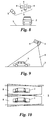
- Fig. 8 shows that the ToF cameras 5 need not necessarily have a parallel view axis, but for example may also be directed at the traffic area 3 at different angles. Also, the individual ToF cameras 5 respectively associated light transmitter 6 may be mounted at different points, for example, to avoid shadowing.
- the individual ToF cameras 5 respectively assigned and separated in their light components light emitter 6 need not necessarily be formed by physically separate light sources.
- one and the same light source could be used, which is time division multiplexed, i. each time is alternately operated for one of the ToF cameras 5 and so forms the light emitter associated with these ToF cameras.
- FIGS. 9 and 10 show yet another advantageous arrangement in which the ToF cameras 5 are directed in the direction of approaching traffic obliquely from above on the traffic area 3.
- the ToF cameras 5 have an oblong image format of 4: 1.
- Vehicles 2 can thus be detected very early and yet be tracked over a longer range.
- the accuracy of the measurement is lower at the beginning of the detection range and increases toward the end of the detection range as the camera becomes closer to the camera.
- an early detection and an accurate distance measurement can be advantageously combined.
- this arrangement can also be used so that the camera is tilted against the direction of travel.
Landscapes
- Physics & Mathematics (AREA)
- Engineering & Computer Science (AREA)
- General Physics & Mathematics (AREA)
- Electromagnetism (AREA)
- Computer Networks & Wireless Communication (AREA)
- Radar, Positioning & Navigation (AREA)
- Remote Sensing (AREA)
- Image Processing (AREA)
- Traffic Control Systems (AREA)
Priority Applications (6)
| Application Number | Priority Date | Filing Date | Title |
|---|---|---|---|
| PT94501897T PT2306426E (pt) | 2009-10-01 | 2009-10-01 | Dispositivo para detecção de veículos sobre uma superfície de circulação |
| SI200930529T SI2306426T1 (sl) | 2009-10-01 | 2009-10-01 | Naprava za detekcijo vozil na prometni površini |
| DK09450189.7T DK2306426T3 (da) | 2009-10-01 | 2009-10-01 | Apparat til detektering af køretøjer i et trafikområde |
| EP09450189A EP2306426B1 (fr) | 2009-10-01 | 2009-10-01 | Dispositif de détection de véhicules sur une voie de circulation |
| ES09450189T ES2401668T3 (es) | 2009-10-01 | 2009-10-01 | Dispositivo para la detección de vehículos en una superficie de tráfico |
| PL09450189T PL2306426T3 (pl) | 2009-10-01 | 2009-10-01 | Urządzenie do wykrywania pojazdów na powierzchni komunikacyjnej |
Applications Claiming Priority (1)
| Application Number | Priority Date | Filing Date | Title |
|---|---|---|---|
| EP09450189A EP2306426B1 (fr) | 2009-10-01 | 2009-10-01 | Dispositif de détection de véhicules sur une voie de circulation |
Publications (2)
| Publication Number | Publication Date |
|---|---|
| EP2306426A1 true EP2306426A1 (fr) | 2011-04-06 |
| EP2306426B1 EP2306426B1 (fr) | 2012-12-19 |
Family
ID=41683358
Family Applications (1)
| Application Number | Title | Priority Date | Filing Date |
|---|---|---|---|
| EP09450189A Active EP2306426B1 (fr) | 2009-10-01 | 2009-10-01 | Dispositif de détection de véhicules sur une voie de circulation |
Country Status (6)
| Country | Link |
|---|---|
| EP (1) | EP2306426B1 (fr) |
| DK (1) | DK2306426T3 (fr) |
| ES (1) | ES2401668T3 (fr) |
| PL (1) | PL2306426T3 (fr) |
| PT (1) | PT2306426E (fr) |
| SI (1) | SI2306426T1 (fr) |
Cited By (11)
| Publication number | Priority date | Publication date | Assignee | Title |
|---|---|---|---|---|
| CN103116988A (zh) * | 2013-01-18 | 2013-05-22 | 合肥工业大学 | 基于tof相机的车流量及车型检测方法 |
| AT513589A1 (de) * | 2012-11-08 | 2014-05-15 | Bluetechnix Gmbh | Aufnahmeverfahren für zumindest zwei ToF-Kameras |
| EP2757346A1 (fr) * | 2013-01-21 | 2014-07-23 | Kapsch TrafficCom AG | Procédé de mesure d'un profil de hauteur d'un véhicule passant sur une route |
| DE102013007886B3 (de) * | 2013-05-08 | 2014-09-25 | Audi Ag | Time-of-Flight-System mit räumlich voneinander getrennten Time-of-Flight-Empfangseinrichtungen und Verfahren zur Abstandsmessung von einem Objekt |
| EP2820632A4 (fr) * | 2012-03-02 | 2015-08-12 | Leddartech Inc | Système et procédé pour une détection et une caractérisation de la circulation à objectifs multiples |
| FR3018940A1 (fr) * | 2014-03-24 | 2015-09-25 | Survision | Systeme de classification automatique de vehicules automobiles |
| US9378640B2 (en) | 2011-06-17 | 2016-06-28 | Leddartech Inc. | System and method for traffic side detection and characterization |
| EP3104357A1 (fr) * | 2015-06-09 | 2016-12-14 | Kapsch TrafficCom AG | Dispositif de détection de véhicules sur une zone de trafic |
| US10488492B2 (en) | 2014-09-09 | 2019-11-26 | Leddarttech Inc. | Discretization of detection zone |
| WO2021250258A1 (fr) * | 2020-06-11 | 2021-12-16 | Continental Automotive Gmbh | Procédé de mise en œuvre d'un dispositif lidar avec descripteurs |
| DE102009046108B4 (de) | 2009-10-28 | 2022-06-09 | pmdtechnologies ag | Kamerasystem |
Citations (5)
| Publication number | Priority date | Publication date | Assignee | Title |
|---|---|---|---|---|
| WO2001085491A1 (fr) * | 2000-05-08 | 2001-11-15 | Automotive Technologies International, Inc. | Systeme de surveillance et d'identification des angles morts d'un vehicule |
| US20020140924A1 (en) * | 1999-01-08 | 2002-10-03 | Richard J. Wangler | Vehicle classification and axle counting sensor system and method |
| EP1454164A2 (fr) | 2001-12-14 | 2004-09-08 | Kapsch Trafficcom AG | Procede et dispositif de mesure geometrique et permettant de determiner la vitesse de vehicules |
| DE60020420T2 (de) * | 1999-02-16 | 2006-05-04 | Mitsubishi Denki K.K. | Situationsdarstellungs-Anzeigesystem |
| DE202008007078U1 (de) * | 2008-05-26 | 2008-09-04 | Signalbau Huber Gmbh | Videodetektion mit PMD-Sensorik |
Family Cites Families (1)
| Publication number | Priority date | Publication date | Assignee | Title |
|---|---|---|---|---|
| US7405812B1 (en) * | 2006-05-18 | 2008-07-29 | Canesta, Inc. | Method and system to avoid inter-system interference for phase-based time-of-flight systems |
-
2009
- 2009-10-01 EP EP09450189A patent/EP2306426B1/fr active Active
- 2009-10-01 DK DK09450189.7T patent/DK2306426T3/da active
- 2009-10-01 PT PT94501897T patent/PT2306426E/pt unknown
- 2009-10-01 SI SI200930529T patent/SI2306426T1/sl unknown
- 2009-10-01 PL PL09450189T patent/PL2306426T3/pl unknown
- 2009-10-01 ES ES09450189T patent/ES2401668T3/es active Active
Patent Citations (5)
| Publication number | Priority date | Publication date | Assignee | Title |
|---|---|---|---|---|
| US20020140924A1 (en) * | 1999-01-08 | 2002-10-03 | Richard J. Wangler | Vehicle classification and axle counting sensor system and method |
| DE60020420T2 (de) * | 1999-02-16 | 2006-05-04 | Mitsubishi Denki K.K. | Situationsdarstellungs-Anzeigesystem |
| WO2001085491A1 (fr) * | 2000-05-08 | 2001-11-15 | Automotive Technologies International, Inc. | Systeme de surveillance et d'identification des angles morts d'un vehicule |
| EP1454164A2 (fr) | 2001-12-14 | 2004-09-08 | Kapsch Trafficcom AG | Procede et dispositif de mesure geometrique et permettant de determiner la vitesse de vehicules |
| DE202008007078U1 (de) * | 2008-05-26 | 2008-09-04 | Signalbau Huber Gmbh | Videodetektion mit PMD-Sensorik |
Non-Patent Citations (1)
| Title |
|---|
| R. SCHWARTE ET AL.: "A New Active 3D-Vision System Based on RF-Modulation Interferometry of Incoherent Light", PHOTONICS EAST-INTELLIGENT SYSTEMS AND ADVANCED MANUFACTURING, PROCEEDINGS OF THE SPIE, vol. 2588, 1995 |
Cited By (20)
| Publication number | Priority date | Publication date | Assignee | Title |
|---|---|---|---|---|
| DE102009046108B4 (de) | 2009-10-28 | 2022-06-09 | pmdtechnologies ag | Kamerasystem |
| US9378640B2 (en) | 2011-06-17 | 2016-06-28 | Leddartech Inc. | System and method for traffic side detection and characterization |
| US9235988B2 (en) | 2012-03-02 | 2016-01-12 | Leddartech Inc. | System and method for multipurpose traffic detection and characterization |
| USRE48914E1 (en) | 2012-03-02 | 2022-02-01 | Leddartech Inc. | System and method for multipurpose traffic detection and characterization |
| EP2820632A4 (fr) * | 2012-03-02 | 2015-08-12 | Leddartech Inc | Système et procédé pour une détection et une caractérisation de la circulation à objectifs multiples |
| USRE50261E1 (en) | 2012-03-02 | 2025-01-07 | Leddartech Inc. | System and method for multipurpose traffic detection and characterization |
| AT513589A1 (de) * | 2012-11-08 | 2014-05-15 | Bluetechnix Gmbh | Aufnahmeverfahren für zumindest zwei ToF-Kameras |
| US9977128B2 (en) | 2012-11-08 | 2018-05-22 | Bluetechnix, GMBH | Recording method for at least two TOF cameras |
| CN103116988B (zh) * | 2013-01-18 | 2014-10-08 | 合肥工业大学 | 基于tof相机的车流量及车型检测方法 |
| CN103116988A (zh) * | 2013-01-18 | 2013-05-22 | 合肥工业大学 | 基于tof相机的车流量及车型检测方法 |
| US9547912B2 (en) | 2013-01-21 | 2017-01-17 | Kapsch Trafficcom Ag | Method for measuring the height profile of a vehicle passing on a road |
| EP2757346A1 (fr) * | 2013-01-21 | 2014-07-23 | Kapsch TrafficCom AG | Procédé de mesure d'un profil de hauteur d'un véhicule passant sur une route |
| DE102013007886B3 (de) * | 2013-05-08 | 2014-09-25 | Audi Ag | Time-of-Flight-System mit räumlich voneinander getrennten Time-of-Flight-Empfangseinrichtungen und Verfahren zur Abstandsmessung von einem Objekt |
| EP2924671A1 (fr) | 2014-03-24 | 2015-09-30 | Survision | Système de classification automatique de véhicules automobiles |
| FR3018940A1 (fr) * | 2014-03-24 | 2015-09-25 | Survision | Systeme de classification automatique de vehicules automobiles |
| US10488492B2 (en) | 2014-09-09 | 2019-11-26 | Leddarttech Inc. | Discretization of detection zone |
| EP3104357A1 (fr) * | 2015-06-09 | 2016-12-14 | Kapsch TrafficCom AG | Dispositif de détection de véhicules sur une zone de trafic |
| WO2016198242A1 (fr) * | 2015-06-09 | 2016-12-15 | Kapsch Trafficcom Ag | Dispositif de détection de véhicules dans une zone de trafic |
| FR3111434A1 (fr) * | 2020-06-11 | 2021-12-17 | Continental Automotive | Procédé de mise en œuvre d’un dispositif LIDAR avec descripteurs |
| WO2021250258A1 (fr) * | 2020-06-11 | 2021-12-16 | Continental Automotive Gmbh | Procédé de mise en œuvre d'un dispositif lidar avec descripteurs |
Also Published As
| Publication number | Publication date |
|---|---|
| PL2306426T3 (pl) | 2013-05-31 |
| SI2306426T1 (sl) | 2013-04-30 |
| PT2306426E (pt) | 2013-03-18 |
| DK2306426T3 (da) | 2013-03-25 |
| ES2401668T3 (es) | 2013-04-23 |
| EP2306426B1 (fr) | 2012-12-19 |
Similar Documents
| Publication | Publication Date | Title |
|---|---|---|
| EP2306426B1 (fr) | Dispositif de détection de véhicules sur une voie de circulation | |
| EP2394234B1 (fr) | Procédé et dispositif de détermination d'un marquage de voie de circulation en vigueur | |
| DE102009023326B4 (de) | Vorrichtung und Verfahren zum Detektieren eines kritischen Bereiches und Fußgängerdetektionsvorrichtung unter Verwendung derselben | |
| DE69736764T2 (de) | Lokales Positionierungsgerät und Verfahren dafür | |
| DE4410406C2 (de) | Optoelektronische Vorrichtung zum Überwachen der Umgebung eines Fahrzeugs | |
| EP2306429B1 (fr) | Dispositif et procédé destinés à la détermination de la direction, de la vitesse et/ou de l'écart de véhicules | |
| EP1634243B1 (fr) | Procede et dispositif de localisation d'objets pour des vehicules a moteur | |
| EP3696537B1 (fr) | Dispositif et procédé de détection des dommages sur un véhicule en déplacement | |
| WO2016026568A1 (fr) | Procédé et dispositif de comptage sans contact d'essieux d'un véhicule et système de comptage d'essieux pour trafic routier | |
| WO2015032709A1 (fr) | Procédé et dispositif de surveillance de la circulation routière pour la constatation d'une circulation dans le mauvais sens d'un véhicule automobile | |
| WO2007033870A1 (fr) | Procede et systeme d'aide a la conduite pour la commande de demarrage d'un vehicule automobile basee sur un capteur | |
| DE19926559A1 (de) | Verfahren und Vorrichtung zur Detektion von Objekten im Umfeld eines Straßenfahrzeugs bis in große Entfernung | |
| EP3520023B1 (fr) | Détection et validation d'objets provenant d'images séquentielles d'une caméra | |
| DE102014112820A1 (de) | Fahrzeugaußenumgebungerkennungsvorrichtung | |
| WO2019063341A1 (fr) | Procédé destiné à détecter une qualité de chaussée d'une chaussée pour un véhicule automobile, système d'assistance à la conduite et véhicule automobile | |
| WO2011045277A1 (fr) | Système de caméra | |
| EP2306425A1 (fr) | Dispositif et procédé destinés à la détection d'axes de roue | |
| WO2010099847A1 (fr) | Procédé et dispositif de détermination d'une portée de visibilité pour un véhicule | |
| EP2341367B1 (fr) | Procédé et agencement de détection des infractions au code de la route dans une zone de feux de signalisation | |
| EP3193276A1 (fr) | Dispositif de detection et procede destine a la reconnaissance d'essieux de vehicule | |
| EP3715779B1 (fr) | Procédé et dispositif de détermination des déformations d'un objet | |
| DE102015223500B4 (de) | Verfahren und Vorrichtung zur Prüfung der Funktionalität einer außenseitigen Lichteinrichtung eines Fahrzeugs | |
| EP2656105B1 (fr) | Procédé pour établir un document image selon lequel un véhicule mesuré par un appareil radar peut être identifié et document image établi par ce procédé | |
| DE102019008840A1 (de) | Verfahren zur Detektion von Objekten auf Schnellstraßen | |
| EP2254104B1 (fr) | Procédé de reconnaissance automatique d'une modification de situation |
Legal Events
| Date | Code | Title | Description |
|---|---|---|---|
| PUAI | Public reference made under article 153(3) epc to a published international application that has entered the european phase |
Free format text: ORIGINAL CODE: 0009012 |
|
| AK | Designated contracting states |
Kind code of ref document: A1 Designated state(s): AT BE BG CH CY CZ DE DK EE ES FI FR GB GR HR HU IE IS IT LI LT LU LV MC MK MT NL NO PL PT RO SE SI SK SM TR |
|
| AX | Request for extension of the european patent |
Extension state: AL BA RS |
|
| 17P | Request for examination filed |
Effective date: 20110919 |
|
| 17Q | First examination report despatched |
Effective date: 20120131 |
|
| RIC1 | Information provided on ipc code assigned before grant |
Ipc: G08G 1/015 20060101AFI20120615BHEP Ipc: G08G 1/04 20060101ALI20120615BHEP Ipc: G01S 17/02 20060101ALI20120615BHEP Ipc: G01S 17/06 20060101ALI20120615BHEP Ipc: G01S 7/48 20060101ALI20120615BHEP Ipc: G01S 17/89 20060101ALI20120615BHEP |
|
| GRAP | Despatch of communication of intention to grant a patent |
Free format text: ORIGINAL CODE: EPIDOSNIGR1 |
|
| GRAS | Grant fee paid |
Free format text: ORIGINAL CODE: EPIDOSNIGR3 |
|
| GRAA | (expected) grant |
Free format text: ORIGINAL CODE: 0009210 |
|
| AK | Designated contracting states |
Kind code of ref document: B1 Designated state(s): AT BE BG CH CY CZ DE DK EE ES FI FR GB GR HR HU IE IS IT LI LT LU LV MC MK MT NL NO PL PT RO SE SI SK SM TR |
|
| REG | Reference to a national code |
Ref country code: GB Ref legal event code: FG4D Free format text: NOT ENGLISH |
|
| REG | Reference to a national code |
Ref country code: CH Ref legal event code: EP |
|
| REG | Reference to a national code |
Ref country code: AT Ref legal event code: REF Ref document number: 589734 Country of ref document: AT Kind code of ref document: T Effective date: 20130115 |
|
| REG | Reference to a national code |
Ref country code: DE Ref legal event code: R096 Ref document number: 502009005728 Country of ref document: DE Effective date: 20130214 |
|
| REG | Reference to a national code |
Ref country code: SE Ref legal event code: TRGR |
|
| REG | Reference to a national code |
Ref country code: CH Ref legal event code: NV Representative=s name: BUECHEL, VON REVY AND PARTNER, CH |
|
| REG | Reference to a national code |
Ref country code: PT Ref legal event code: SC4A Free format text: AVAILABILITY OF NATIONAL TRANSLATION Effective date: 20130308 |
|
| REG | Reference to a national code |
Ref country code: DK Ref legal event code: T3 |
|
| REG | Reference to a national code |
Ref country code: ES Ref legal event code: FG2A Ref document number: 2401668 Country of ref document: ES Kind code of ref document: T3 Effective date: 20130423 |
|
| REG | Reference to a national code |
Ref country code: NL Ref legal event code: T3 |
|
| PG25 | Lapsed in a contracting state [announced via postgrant information from national office to epo] |
Ref country code: FI Free format text: LAPSE BECAUSE OF FAILURE TO SUBMIT A TRANSLATION OF THE DESCRIPTION OR TO PAY THE FEE WITHIN THE PRESCRIBED TIME-LIMIT Effective date: 20121219 Ref country code: LT Free format text: LAPSE BECAUSE OF FAILURE TO SUBMIT A TRANSLATION OF THE DESCRIPTION OR TO PAY THE FEE WITHIN THE PRESCRIBED TIME-LIMIT Effective date: 20121219 |
|
| REG | Reference to a national code |
Ref country code: CH Ref legal event code: NV Representative=s name: PATWIL AG, CH |
|
| REG | Reference to a national code |
Ref country code: SK Ref legal event code: T3 Ref document number: E 13471 Country of ref document: SK |
|
| REG | Reference to a national code |
Ref country code: NO Ref legal event code: T2 Effective date: 20121219 |
|
| REG | Reference to a national code |
Ref country code: LT Ref legal event code: MG4D |
|
| PG25 | Lapsed in a contracting state [announced via postgrant information from national office to epo] |
Ref country code: GR Free format text: LAPSE BECAUSE OF FAILURE TO SUBMIT A TRANSLATION OF THE DESCRIPTION OR TO PAY THE FEE WITHIN THE PRESCRIBED TIME-LIMIT Effective date: 20130320 Ref country code: LV Free format text: LAPSE BECAUSE OF FAILURE TO SUBMIT A TRANSLATION OF THE DESCRIPTION OR TO PAY THE FEE WITHIN THE PRESCRIBED TIME-LIMIT Effective date: 20121219 |
|
| REG | Reference to a national code |
Ref country code: PL Ref legal event code: T3 |
|
| REG | Reference to a national code |
Ref country code: HU Ref legal event code: AG4A Ref document number: E015741 Country of ref document: HU |
|
| PG25 | Lapsed in a contracting state [announced via postgrant information from national office to epo] |
Ref country code: EE Free format text: LAPSE BECAUSE OF FAILURE TO SUBMIT A TRANSLATION OF THE DESCRIPTION OR TO PAY THE FEE WITHIN THE PRESCRIBED TIME-LIMIT Effective date: 20121219 Ref country code: BG Free format text: LAPSE BECAUSE OF FAILURE TO SUBMIT A TRANSLATION OF THE DESCRIPTION OR TO PAY THE FEE WITHIN THE PRESCRIBED TIME-LIMIT Effective date: 20130319 Ref country code: IS Free format text: LAPSE BECAUSE OF FAILURE TO SUBMIT A TRANSLATION OF THE DESCRIPTION OR TO PAY THE FEE WITHIN THE PRESCRIBED TIME-LIMIT Effective date: 20130419 |
|
| PG25 | Lapsed in a contracting state [announced via postgrant information from national office to epo] |
Ref country code: RO Free format text: LAPSE BECAUSE OF FAILURE TO SUBMIT A TRANSLATION OF THE DESCRIPTION OR TO PAY THE FEE WITHIN THE PRESCRIBED TIME-LIMIT Effective date: 20121219 |
|
| PLBE | No opposition filed within time limit |
Free format text: ORIGINAL CODE: 0009261 |
|
| STAA | Information on the status of an ep patent application or granted ep patent |
Free format text: STATUS: NO OPPOSITION FILED WITHIN TIME LIMIT |
|
| 26N | No opposition filed |
Effective date: 20130920 |
|
| PG25 | Lapsed in a contracting state [announced via postgrant information from national office to epo] |
Ref country code: CY Free format text: LAPSE BECAUSE OF FAILURE TO SUBMIT A TRANSLATION OF THE DESCRIPTION OR TO PAY THE FEE WITHIN THE PRESCRIBED TIME-LIMIT Effective date: 20121219 Ref country code: HR Free format text: LAPSE BECAUSE OF FAILURE TO SUBMIT A TRANSLATION OF THE DESCRIPTION OR TO PAY THE FEE WITHIN THE PRESCRIBED TIME-LIMIT Effective date: 20121219 |
|
| REG | Reference to a national code |
Ref country code: DE Ref legal event code: R097 Ref document number: 502009005728 Country of ref document: DE Effective date: 20130920 |
|
| PG25 | Lapsed in a contracting state [announced via postgrant information from national office to epo] |
Ref country code: MC Free format text: LAPSE BECAUSE OF FAILURE TO SUBMIT A TRANSLATION OF THE DESCRIPTION OR TO PAY THE FEE WITHIN THE PRESCRIBED TIME-LIMIT Effective date: 20121219 |
|
| REG | Reference to a national code |
Ref country code: IE Ref legal event code: MM4A |
|
| PG25 | Lapsed in a contracting state [announced via postgrant information from national office to epo] |
Ref country code: IE Free format text: LAPSE BECAUSE OF NON-PAYMENT OF DUE FEES Effective date: 20131001 |
|
| PG25 | Lapsed in a contracting state [announced via postgrant information from national office to epo] |
Ref country code: SM Free format text: LAPSE BECAUSE OF FAILURE TO SUBMIT A TRANSLATION OF THE DESCRIPTION OR TO PAY THE FEE WITHIN THE PRESCRIBED TIME-LIMIT Effective date: 20121219 |
|
| PG25 | Lapsed in a contracting state [announced via postgrant information from national office to epo] |
Ref country code: TR Free format text: LAPSE BECAUSE OF FAILURE TO SUBMIT A TRANSLATION OF THE DESCRIPTION OR TO PAY THE FEE WITHIN THE PRESCRIBED TIME-LIMIT Effective date: 20121219 |
|
| PG25 | Lapsed in a contracting state [announced via postgrant information from national office to epo] |
Ref country code: LU Free format text: LAPSE BECAUSE OF NON-PAYMENT OF DUE FEES Effective date: 20131001 Ref country code: MK Free format text: LAPSE BECAUSE OF FAILURE TO SUBMIT A TRANSLATION OF THE DESCRIPTION OR TO PAY THE FEE WITHIN THE PRESCRIBED TIME-LIMIT Effective date: 20121219 |
|
| PG25 | Lapsed in a contracting state [announced via postgrant information from national office to epo] |
Ref country code: MT Free format text: LAPSE BECAUSE OF FAILURE TO SUBMIT A TRANSLATION OF THE DESCRIPTION OR TO PAY THE FEE WITHIN THE PRESCRIBED TIME-LIMIT Effective date: 20121219 |
|
| REG | Reference to a national code |
Ref country code: FR Ref legal event code: PLFP Year of fee payment: 7 |
|
| REG | Reference to a national code |
Ref country code: FR Ref legal event code: PLFP Year of fee payment: 8 |
|
| PGFP | Annual fee paid to national office [announced via postgrant information from national office to epo] |
Ref country code: SK Payment date: 20160930 Year of fee payment: 8 Ref country code: PL Payment date: 20160929 Year of fee payment: 8 |
|
| PGFP | Annual fee paid to national office [announced via postgrant information from national office to epo] |
Ref country code: CZ Payment date: 20160930 Year of fee payment: 8 Ref country code: NO Payment date: 20161024 Year of fee payment: 8 Ref country code: GB Payment date: 20161020 Year of fee payment: 8 Ref country code: DK Payment date: 20161019 Year of fee payment: 8 Ref country code: HU Payment date: 20161019 Year of fee payment: 8 Ref country code: NL Payment date: 20161019 Year of fee payment: 8 Ref country code: CH Payment date: 20161020 Year of fee payment: 8 |
|
| PGFP | Annual fee paid to national office [announced via postgrant information from national office to epo] |
Ref country code: PT Payment date: 20161003 Year of fee payment: 8 Ref country code: SI Payment date: 20160923 Year of fee payment: 8 Ref country code: BE Payment date: 20161019 Year of fee payment: 8 Ref country code: IT Payment date: 20161024 Year of fee payment: 8 |
|
| REG | Reference to a national code |
Ref country code: FR Ref legal event code: PLFP Year of fee payment: 9 |
|
| PG25 | Lapsed in a contracting state [announced via postgrant information from national office to epo] |
Ref country code: CZ Free format text: LAPSE BECAUSE OF NON-PAYMENT OF DUE FEES Effective date: 20171001 |
|
| REG | Reference to a national code |
Ref country code: DK Ref legal event code: EBP Effective date: 20171031 |
|
| REG | Reference to a national code |
Ref country code: NO Ref legal event code: MMEP |
|
| REG | Reference to a national code |
Ref country code: CH Ref legal event code: PL |
|
| REG | Reference to a national code |
Ref country code: NL Ref legal event code: MM Effective date: 20171101 |
|
| GBPC | Gb: european patent ceased through non-payment of renewal fee |
Effective date: 20171001 |
|
| REG | Reference to a national code |
Ref country code: SI Ref legal event code: KO00 Effective date: 20180508 |
|
| REG | Reference to a national code |
Ref country code: SK Ref legal event code: MM4A Ref document number: E 13471 Country of ref document: SK Effective date: 20171001 |
|
| PG25 | Lapsed in a contracting state [announced via postgrant information from national office to epo] |
Ref country code: CH Free format text: LAPSE BECAUSE OF NON-PAYMENT OF DUE FEES Effective date: 20171031 Ref country code: SK Free format text: LAPSE BECAUSE OF NON-PAYMENT OF DUE FEES Effective date: 20171001 Ref country code: PT Free format text: LAPSE BECAUSE OF NON-PAYMENT OF DUE FEES Effective date: 20180402 Ref country code: NO Free format text: LAPSE BECAUSE OF NON-PAYMENT OF DUE FEES Effective date: 20171031 Ref country code: LI Free format text: LAPSE BECAUSE OF NON-PAYMENT OF DUE FEES Effective date: 20171031 Ref country code: GB Free format text: LAPSE BECAUSE OF NON-PAYMENT OF DUE FEES Effective date: 20171001 Ref country code: NL Free format text: LAPSE BECAUSE OF NON-PAYMENT OF DUE FEES Effective date: 20171101 |
|
| REG | Reference to a national code |
Ref country code: BE Ref legal event code: MM Effective date: 20171031 |
|
| PG25 | Lapsed in a contracting state [announced via postgrant information from national office to epo] |
Ref country code: BE Free format text: LAPSE BECAUSE OF NON-PAYMENT OF DUE FEES Effective date: 20171031 Ref country code: SI Free format text: LAPSE BECAUSE OF NON-PAYMENT OF DUE FEES Effective date: 20171002 Ref country code: HU Free format text: LAPSE BECAUSE OF NON-PAYMENT OF DUE FEES Effective date: 20171002 |
|
| REG | Reference to a national code |
Ref country code: FR Ref legal event code: PLFP Year of fee payment: 10 |
|
| PG25 | Lapsed in a contracting state [announced via postgrant information from national office to epo] |
Ref country code: IT Free format text: LAPSE BECAUSE OF NON-PAYMENT OF DUE FEES Effective date: 20171001 |
|
| PG25 | Lapsed in a contracting state [announced via postgrant information from national office to epo] |
Ref country code: DK Free format text: LAPSE BECAUSE OF NON-PAYMENT OF DUE FEES Effective date: 20171031 |
|
| PG25 | Lapsed in a contracting state [announced via postgrant information from national office to epo] |
Ref country code: PL Free format text: LAPSE BECAUSE OF NON-PAYMENT OF DUE FEES Effective date: 20171001 |
|
| P01 | Opt-out of the competence of the unified patent court (upc) registered |
Effective date: 20230513 |
|
| PGFP | Annual fee paid to national office [announced via postgrant information from national office to epo] |
Ref country code: DE Payment date: 20241021 Year of fee payment: 16 |
|
| PGFP | Annual fee paid to national office [announced via postgrant information from national office to epo] |
Ref country code: FR Payment date: 20241021 Year of fee payment: 16 Ref country code: AT Payment date: 20241022 Year of fee payment: 16 |
|
| PGFP | Annual fee paid to national office [announced via postgrant information from national office to epo] |
Ref country code: ES Payment date: 20241127 Year of fee payment: 16 |
|
| PGFP | Annual fee paid to national office [announced via postgrant information from national office to epo] |
Ref country code: SE Payment date: 20241021 Year of fee payment: 16 |