EP2306573A1 - Festoxid-Brennstoffzellenvorrichtung - Google Patents
Festoxid-Brennstoffzellenvorrichtung Download PDFInfo
- Publication number
- EP2306573A1 EP2306573A1 EP10181370A EP10181370A EP2306573A1 EP 2306573 A1 EP2306573 A1 EP 2306573A1 EP 10181370 A EP10181370 A EP 10181370A EP 10181370 A EP10181370 A EP 10181370A EP 2306573 A1 EP2306573 A1 EP 2306573A1
- Authority
- EP
- European Patent Office
- Prior art keywords
- fuel cell
- fuel
- amount
- temperature
- inverter permitted
- Prior art date
- Legal status (The legal status is an assumption and is not a legal conclusion. Google has not performed a legal analysis and makes no representation as to the accuracy of the status listed.)
- Granted
Links
- 239000000446 fuel Substances 0.000 title claims abstract description 428
- 239000007787 solid Substances 0.000 title claims abstract description 77
- 230000008859 change Effects 0.000 claims abstract description 211
- 238000002407 reforming Methods 0.000 claims abstract description 30
- 230000004044 response Effects 0.000 claims abstract description 10
- 238000001514 detection method Methods 0.000 claims description 9
- 238000000034 method Methods 0.000 claims description 8
- 239000002737 fuel gas Substances 0.000 description 38
- XLYOFNOQVPJJNP-UHFFFAOYSA-N water Substances O XLYOFNOQVPJJNP-UHFFFAOYSA-N 0.000 description 38
- 238000006243 chemical reaction Methods 0.000 description 32
- 239000007789 gas Substances 0.000 description 32
- 238000002485 combustion reaction Methods 0.000 description 29
- 238000012937 correction Methods 0.000 description 27
- 238000006057 reforming reaction Methods 0.000 description 22
- 230000015556 catabolic process Effects 0.000 description 14
- 238000006731 degradation reaction Methods 0.000 description 14
- 238000010586 diagram Methods 0.000 description 14
- QVGXLLKOCUKJST-UHFFFAOYSA-N atomic oxygen Chemical compound [O] QVGXLLKOCUKJST-UHFFFAOYSA-N 0.000 description 11
- 230000001934 delay Effects 0.000 description 11
- 239000001301 oxygen Substances 0.000 description 11
- 229910052760 oxygen Inorganic materials 0.000 description 11
- 230000002547 anomalous effect Effects 0.000 description 10
- 230000007423 decrease Effects 0.000 description 10
- 230000003247 decreasing effect Effects 0.000 description 9
- 238000000629 steam reforming Methods 0.000 description 9
- 238000010438 heat treatment Methods 0.000 description 8
- PXHVJJICTQNCMI-UHFFFAOYSA-N Nickel Chemical compound [Ni] PXHVJJICTQNCMI-UHFFFAOYSA-N 0.000 description 7
- 230000003647 oxidation Effects 0.000 description 7
- 238000007254 oxidation reaction Methods 0.000 description 7
- 230000005611 electricity Effects 0.000 description 6
- 229910052739 hydrogen Inorganic materials 0.000 description 6
- 238000002453 autothermal reforming Methods 0.000 description 5
- 238000009826 distribution Methods 0.000 description 5
- 238000000605 extraction Methods 0.000 description 5
- 239000001257 hydrogen Substances 0.000 description 5
- 230000008569 process Effects 0.000 description 5
- 229910052712 strontium Inorganic materials 0.000 description 5
- UFHFLCQGNIYNRP-UHFFFAOYSA-N Hydrogen Chemical compound [H][H] UFHFLCQGNIYNRP-UHFFFAOYSA-N 0.000 description 4
- MCMNRKCIXSYSNV-UHFFFAOYSA-N Zirconium dioxide Chemical compound O=[Zr]=O MCMNRKCIXSYSNV-UHFFFAOYSA-N 0.000 description 4
- 230000002159 abnormal effect Effects 0.000 description 4
- 239000003792 electrolyte Substances 0.000 description 4
- 229910052746 lanthanum Inorganic materials 0.000 description 4
- FZLIPJUXYLNCLC-UHFFFAOYSA-N lanthanum atom Chemical compound [La] FZLIPJUXYLNCLC-UHFFFAOYSA-N 0.000 description 4
- 239000007800 oxidant agent Substances 0.000 description 4
- 229910052761 rare earth metal Inorganic materials 0.000 description 4
- 238000011144 upstream manufacturing Methods 0.000 description 4
- 239000003054 catalyst Substances 0.000 description 3
- 230000001276 controlling effect Effects 0.000 description 3
- 230000006872 improvement Effects 0.000 description 3
- 239000011810 insulating material Substances 0.000 description 3
- 239000000203 mixture Substances 0.000 description 3
- 229910052759 nickel Inorganic materials 0.000 description 3
- 230000001590 oxidative effect Effects 0.000 description 3
- 230000001105 regulatory effect Effects 0.000 description 3
- NBIIXXVUZAFLBC-UHFFFAOYSA-N Phosphoric acid Chemical compound OP(O)(O)=O NBIIXXVUZAFLBC-UHFFFAOYSA-N 0.000 description 2
- 239000003570 air Substances 0.000 description 2
- PNEYBMLMFCGWSK-UHFFFAOYSA-N aluminium oxide Inorganic materials [O-2].[O-2].[O-2].[Al+3].[Al+3] PNEYBMLMFCGWSK-UHFFFAOYSA-N 0.000 description 2
- 229910052791 calcium Inorganic materials 0.000 description 2
- CETPSERCERDGAM-UHFFFAOYSA-N ceric oxide Chemical compound O=[Ce]=O CETPSERCERDGAM-UHFFFAOYSA-N 0.000 description 2
- 229910000422 cerium(IV) oxide Inorganic materials 0.000 description 2
- 230000009977 dual effect Effects 0.000 description 2
- 230000000694 effects Effects 0.000 description 2
- 230000006870 function Effects 0.000 description 2
- LNTHITQWFMADLM-UHFFFAOYSA-N gallic acid Chemical compound OC(=O)C1=CC(O)=C(O)C(O)=C1 LNTHITQWFMADLM-UHFFFAOYSA-N 0.000 description 2
- 229910052742 iron Inorganic materials 0.000 description 2
- 238000010248 power generation Methods 0.000 description 2
- 238000011160 research Methods 0.000 description 2
- 229910052706 scandium Inorganic materials 0.000 description 2
- 230000035945 sensitivity Effects 0.000 description 2
- 230000006641 stabilisation Effects 0.000 description 2
- 238000011105 stabilization Methods 0.000 description 2
- 230000000087 stabilizing effect Effects 0.000 description 2
- 238000003860 storage Methods 0.000 description 2
- 230000007704 transition Effects 0.000 description 2
- 229910052727 yttrium Inorganic materials 0.000 description 2
- KJTLSVCANCCWHF-UHFFFAOYSA-N Ruthenium Chemical compound [Ru] KJTLSVCANCCWHF-UHFFFAOYSA-N 0.000 description 1
- BQENXCOZCUHKRE-UHFFFAOYSA-N [La+3].[La+3].[O-][Mn]([O-])=O.[O-][Mn]([O-])=O.[O-][Mn]([O-])=O Chemical compound [La+3].[La+3].[O-][Mn]([O-])=O.[O-][Mn]([O-])=O.[O-][Mn]([O-])=O BQENXCOZCUHKRE-UHFFFAOYSA-N 0.000 description 1
- 229910000147 aluminium phosphate Inorganic materials 0.000 description 1
- 238000013459 approach Methods 0.000 description 1
- 229910052963 cobaltite Inorganic materials 0.000 description 1
- 238000001816 cooling Methods 0.000 description 1
- 230000002950 deficient Effects 0.000 description 1
- 238000013461 design Methods 0.000 description 1
- 230000003009 desulfurizing effect Effects 0.000 description 1
- 238000011161 development Methods 0.000 description 1
- 230000003292 diminished effect Effects 0.000 description 1
- 230000002349 favourable effect Effects 0.000 description 1
- 238000001914 filtration Methods 0.000 description 1
- 239000010763 heavy fuel oil Substances 0.000 description 1
- 150000002431 hydrogen Chemical class 0.000 description 1
- 238000004519 manufacturing process Methods 0.000 description 1
- 239000000463 material Substances 0.000 description 1
- 230000001404 mediated effect Effects 0.000 description 1
- 238000012986 modification Methods 0.000 description 1
- 230000004048 modification Effects 0.000 description 1
- 230000008447 perception Effects 0.000 description 1
- 230000002250 progressing effect Effects 0.000 description 1
- 230000000630 rising effect Effects 0.000 description 1
- 229910052707 ruthenium Inorganic materials 0.000 description 1
- 238000004904 shortening Methods 0.000 description 1
- 239000007784 solid electrolyte Substances 0.000 description 1
- 230000001629 suppression Effects 0.000 description 1
- 230000008016 vaporization Effects 0.000 description 1
- 239000002699 waste material Substances 0.000 description 1
- 229910009112 xH2O Inorganic materials 0.000 description 1
- 229910000859 α-Fe Inorganic materials 0.000 description 1
Images





Classifications
-
- H—ELECTRICITY
- H01—ELECTRIC ELEMENTS
- H01M—PROCESSES OR MEANS, e.g. BATTERIES, FOR THE DIRECT CONVERSION OF CHEMICAL ENERGY INTO ELECTRICAL ENERGY
- H01M8/00—Fuel cells; Manufacture thereof
- H01M8/04—Auxiliary arrangements, e.g. for control of pressure or for circulation of fluids
- H01M8/04082—Arrangements for control of reactant parameters, e.g. pressure or concentration
- H01M8/04201—Reactant storage and supply, e.g. means for feeding, pipes
-
- H—ELECTRICITY
- H01—ELECTRIC ELEMENTS
- H01M—PROCESSES OR MEANS, e.g. BATTERIES, FOR THE DIRECT CONVERSION OF CHEMICAL ENERGY INTO ELECTRICAL ENERGY
- H01M8/00—Fuel cells; Manufacture thereof
- H01M8/04—Auxiliary arrangements, e.g. for control of pressure or for circulation of fluids
- H01M8/04298—Processes for controlling fuel cells or fuel cell systems
- H01M8/04313—Processes for controlling fuel cells or fuel cell systems characterised by the detection or assessment of variables; characterised by the detection or assessment of failure or abnormal function
- H01M8/0432—Temperature; Ambient temperature
-
- H—ELECTRICITY
- H01—ELECTRIC ELEMENTS
- H01M—PROCESSES OR MEANS, e.g. BATTERIES, FOR THE DIRECT CONVERSION OF CHEMICAL ENERGY INTO ELECTRICAL ENERGY
- H01M8/00—Fuel cells; Manufacture thereof
- H01M8/04—Auxiliary arrangements, e.g. for control of pressure or for circulation of fluids
- H01M8/04298—Processes for controlling fuel cells or fuel cell systems
- H01M8/04694—Processes for controlling fuel cells or fuel cell systems characterised by variables to be controlled
- H01M8/04746—Pressure; Flow
- H01M8/04753—Pressure; Flow of fuel cell reactants
-
- H—ELECTRICITY
- H01—ELECTRIC ELEMENTS
- H01M—PROCESSES OR MEANS, e.g. BATTERIES, FOR THE DIRECT CONVERSION OF CHEMICAL ENERGY INTO ELECTRICAL ENERGY
- H01M8/00—Fuel cells; Manufacture thereof
- H01M8/04—Auxiliary arrangements, e.g. for control of pressure or for circulation of fluids
- H01M8/04298—Processes for controlling fuel cells or fuel cell systems
- H01M8/04694—Processes for controlling fuel cells or fuel cell systems characterised by variables to be controlled
- H01M8/04858—Electric variables
- H01M8/04925—Power, energy, capacity or load
- H01M8/0494—Power, energy, capacity or load of fuel cell stacks
-
- H—ELECTRICITY
- H01—ELECTRIC ELEMENTS
- H01M—PROCESSES OR MEANS, e.g. BATTERIES, FOR THE DIRECT CONVERSION OF CHEMICAL ENERGY INTO ELECTRICAL ENERGY
- H01M8/00—Fuel cells; Manufacture thereof
- H01M8/10—Fuel cells with solid electrolytes
- H01M8/12—Fuel cells with solid electrolytes operating at high temperature, e.g. with stabilised ZrO2 electrolyte
- H01M2008/1293—Fuel cells with solid oxide electrolytes
-
- Y—GENERAL TAGGING OF NEW TECHNOLOGICAL DEVELOPMENTS; GENERAL TAGGING OF CROSS-SECTIONAL TECHNOLOGIES SPANNING OVER SEVERAL SECTIONS OF THE IPC; TECHNICAL SUBJECTS COVERED BY FORMER USPC CROSS-REFERENCE ART COLLECTIONS [XRACs] AND DIGESTS
- Y02—TECHNOLOGIES OR APPLICATIONS FOR MITIGATION OR ADAPTATION AGAINST CLIMATE CHANGE
- Y02E—REDUCTION OF GREENHOUSE GAS [GHG] EMISSIONS, RELATED TO ENERGY GENERATION, TRANSMISSION OR DISTRIBUTION
- Y02E60/00—Enabling technologies; Technologies with a potential or indirect contribution to GHG emissions mitigation
- Y02E60/30—Hydrogen technology
- Y02E60/50—Fuel cells
Definitions
- the present invention relates to a solid oxide fuel cell device, and more particularly to a solid oxide fuel cell device furnished with a load following function for changing the amount of fuel supplied in accordance with the amount of required power load.
- the most important issue in attaining a practical fuel cell device is how to achieve the two-fold goal of preventing fuel cell breakage and saving energy (reduce electrical grid power from commercial power sources and increase generated power from fuel cells).
- SOFC solid oxide fuel cell
- JP-07-307163-A discloses a fuel cell device (a phosphoric acid fuel cell device) in which power is output by instructing an inverter permitted current value to the fuel cell, using a delay time after instructing a gas increase or decrease amount determined by the amount of change in load; in the method of JP-07-307163-A , breakage of fuel cells caused by fuel depletion can be suppressed, since during load following power is not extracted until the amount of fuel is ideal.
- this type of time delay occurs when extracting electrical power, load following characteristics are degraded, so from an energy saving standpoint, this solution alone is not enough.
- the fuel cell of JP-07-307163- A is thus unable to solve the dual problem of increasing energy saving performance and preventing breakage of fuel cells.
- JP-2007-220620-A describes a fuel cell device in which, when the temperature of the gas reforming section (the reformer) falls below a predetermined temperature, the gradual increase in output from the fuel cell main unit to the power conversion section (the inverter) is stopped and the current status is maintained, and when the temperature exceeds a predetermined temperature, a gradual increase is implemented, so that when there is temporarily insufficient heating of the reformer due to deficient supply of fuel or the like, operational halting of the device is prevented.
- inverter permitted current value inverter permitted power value
- inverter permitted power value indicating the power to be obtained from a fuel cell device
- fuel cell device because of delays in supply of fuel and water to the reformer, delays in the reforming reaction, and, as described above, uncertain time delays under various conditions in the fuel cell device as well, it occurs that ideal conditions may not be achieved due to various time delays in the SOFC device, even when the inverter permitted current value rate of increase or rate of decrease are changed to ideal design values, thereby leading to the issue (problem) of fuel cell breakage.
- these characteristics of fuel cell device mean that feedback control is difficult, and there is no alternative to implementing feed forward control. For this reason, it was conventionally believed that speeding up load following would be difficult.
- the SOFC device had inherent major problems of its own. For example, with general use storage batteries it is physically impossible to extract an amount of electrical power from a storage battery which exceeds the limit of what can extracted, and breakage does not occur, so control can be easily implemented. In the SOFC device, however, if an instruction to extract electrical power in excess of a limit value is given, that power can be extracted from the fuel cells, and that excessive power extraction leads to breakage of the fuel cells. Because of this inherent problem, the perception has been that very high precision control must be imposed on the SOFC device in order to improve load following performance amidst the elements of uncertainty, thus making it extremely difficult to improve SOFC energy saving performance.
- the present inventors have discovered similar unstable states in which uncertain variability occurs in solid oxide fuel cell device as the result of changes in the state of various parameters such as the reformer temperature state, the fuel cell stack temperature state, outside air temperature, and fuel cell anomalies (degradation), and seek to simultaneously resolve these problems and improve reliability.
- a solid oxide fuel cell device with a load following function for changing a fuel supply rate in response to a load defined as a required power determined by demand power, comprising: a fuel cell module having a fuel cell stack composed of a plurality of solid oxide fuel cells and a reformer for reforming fuel and supplying the fuel to the fuel cells; inverter means for receiving electrical power generated by the fuel cell module and converting the power to alternating power; command power value setting means for setting a command power value to be generated by the fuel cell module based on an amount of the load; fuel control means for determining an fuel supply rate and supplying the fuel by the fuel supply rate to the fuel cells so as to generate the command power value; inverter permitted power value instruction means for instructing to the inverter means an inverter permitted power value corresponding to the command power value, which is the permitted amount of power to be extracted from the fuel cell module, after the fuel has been supplied by the fuel supply rate to the fuel cells by the fuel control means; and inverter permitted power value
- a fuel supply rate and a command power value to be generated by the fuel cell module are set based on the amount of load; next, an inverter permitted power value corresponding to the amount of power permitted to be extracted from the fuel cell module is instructed to the inverter means, whereupon the state of the solid oxide fuel cell (SOFC) device reforming reaction and changes in conditions under which air, fuel, and the like reach the entirety of the fuel cells are added, and the amount of change per unit time in the inverter permitted power value is changed based on the temperature inside the fuel cell module, therefore fuel cell breakage associated with fuel runout and air runout can be prevented while load following characteristics are improved so that generated power obtained from the fuel cell device is increased and grid power obtained from commercial power sources is decreased, thereby saving energy.
- SOFC solid oxide fuel cell
- the amount of change per unit time in the inverter permitted power value is changed to be large in the high temperature region within the temperature region equal to or lower than a first predetermined temperature, thereby allowing for increased load following performance, and the amount of change per unit time in the inverter permitted power value is changed to be small in the low temperature region within the temperature region equal to or lower than the first predetermined temperature, thereby assuring fuel cell device performance and increasing energy savings.
- the amount of change per unit time in the inverter permitted power value is changed so that change is smaller, the higher the temperature is, in the temperature region equal to or higher than the second predetermined temperature, therefore further degradation of the fuel cells can be prevented and reliability improved while assuring energy saving performance.
- the temperature inside the fuel cell module is the temperature of the reformer
- the solid oxide fuel cell device further comprises reformer temperature detection means for detecting the temperature of the reformer.
- the amount of change per unit time in the inverter permitted power value is changed based on the temperature of the reformer, which indicates changes in the reforming reaction, therefore the amount of change per unit time in the inverter permitted power value (the rate of change) can be optimized by absorbing changes in the reformer reforming reaction, thereby increasing fuel cell reliability and energy saving performance.
- the reforming reaction is in a stable state when the reformer temperature is in the high temperature region within the temperature region equal to or lower than the first predetermined temperature, the amount of change per unit time in the inverter permitted power value can be changed to become large so as to raise load following performance; when the temperature of the reformer is in the low temperature region within the temperature region equal to or lower than the first predetermined temperature, the reforming reaction is insufficient, therefore a change is made so that the amount of change per unit time in the inverter permitted power value becomes small, and fuel cell reliability can be assured while energy saving performance is improved.
- the temperature inside the fuel cell module is the temperature of the fuel cell stack
- the solid oxide fuel cell device further comprises stack temperature detection means for detecting the temperature of the fuel cell stack.
- the generating reaction in the fuel cell stack is stable when the fuel cell stack is in the high temperature region within the temperature region equal to or lower than the first predetermined temperature, the amount of change per unit time in the inverter permitted power value can be changed to be large so as to increase load following performance, resulting in an improvement in energy saving performance while assuring fuel cell reliability.
- the possibility can be conceived of anomalies (degradation) in the fuel cells, if the fuel cell stack temperature is in an anomalous high temperature region which is equal to or higher than the second predetermined temperature, and of a drop in oxygen concentration occurring when generating air supplied to the fuel cell stack expands beyond the normal level but the amount of oxygen contained in that air does not change, thus decreasing the amount of oxygen supplied to the fuel cells and consequently decreasing the amount of oxygen capable of being involved in electrical generation; in such cases the amount of change per unit time in the inverter permitted power value is changed to be small, thereby increasing reliability of the fuel cells while assuring energy savings.
- anomalies degradation
- the inverter permitted power value change means controls the amount of change per unit time in the inverter permitted power value so as to be constant in a temperature region between the first predetermined temperature and the second predetermined temperature.
- the generating reaction and reforming reaction are stable in the temperature regions between the first predetermined temperature and the second predetermined temperature, therefore a stable state of the generating reaction and the reforming reaction can be maintained by keeping the temperature constant, without excessively changing the amount of change per unit time in the inverter permitted power value; this enables reliability of the fuel cells to be increased while increasing energy saving performance.
- a solid oxide fuel cell (SOFC) device according to an embodiment of the present invention will be explained.
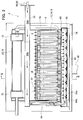
- a solid oxide fuel cell (SOFC) device according to an embodiment of the present invention is furnished with a fuel cell module 2 and an auxiliary unit 4.
- the fuel cell module 2 is furnished with a housing 6; a sealed space 8 is formed within the housing 6, mediated by insulating material (not shown, however the insulating material is not an indispensable structure and may be omitted). Note that it is acceptable to provide no insulating material.
- a fuel cell assembly 12 for carrying out the power generating reaction between fuel gas and oxidant (air) is disposed in the power generating chamber 10 at the lower portion of this sealed space 8.
- This fuel cell assembly 12 is furnished with ten fuel cell stacks 14 (see Fig. 5 ), and the fuel cell stack 14 comprises 16 fuel cell units 16 (see Fig. 4 ).
- the fuel cell assembly 12 has 160 fuel cell units 16, all of which are serially connected.
- a combustion chamber 18 is formed above the aforementioned power generating chamber 10 in the sealed space 8 of the fuel cell module 2. Residual fuel gas and residual oxidant (air) not used in the power generation reaction is combusted in this combustion chamber 18 to produce exhaust gas.
- a reformer 20 for reforming fuel gas is disposed at the top of the combustion chamber 18; the reformer 20 is heated by the heat of residual gas combustion to a temperature at which the reforming reaction can take place.
- An air heat exchanger 22 for receiving the heat of combustion and heating the air is further disposed above this reformer 20.
- the auxiliary unit 4 is furnished with a pure water tank 26 for holding water from a municipal or other water supply source 24 and filtering it into pure water, and a water flow rate regulator unit 28 (a "water pump” or the like driven by a motor) for regulating the flow rate (litter per minute) of water supplied from the reservoir tank.
- the auxiliary unit 4 is further furnished with a gas shutoff valve 32 for shutting off the fuel gas supply from a fuel supply source 30 such as municipal gas or the like, a desulfurizer 36 for desulfurizing the fuel gas, and a fuel gas flow rate regulator unit 38 (a "fuel pump” or the like driven by a motor) for regulating the flow rate (litter per minute) of fuel gas.
- an auxiliary unit 4 is furnished with an electromagnetic valve 42 for shutting off air serving as an oxidant and supplied from an air supply source 40, and a reforming air flow rate regulator unit 44 and generating air flow rate regulator unit 45 ("air blower" or the like driven by a motor) for regulating air flow rate (litter per minute).
- a heating means such as a heater for heating the reforming air supply to the reformer 20 or the power generating air supply to the power generating chamber 10 in order to efficiently raise the temperature at startup, nor is there a heating means for separately heating the reformer 20.
- a hot-water producing device 50 supplied with exhaust gas is connected to the fuel cell module 2.
- Municipal water from a water supply source 24 is supplied to this hot-water producing device 50; this water is turned into hot water by the heat of the exhaust gas, and is supplied to a hot water reservoir tank in an external water heater (not shown).
- the fuel cell module 2 is provided with a control box 52 for controlling the supply flow rates of fuel gas and the like.
- an inverter 54 serving as an electrical power extraction unit (electrical power conversion unit) for supplying electrical power generated by the fuel cell module to the outside is connected to the fuel cell module 2.
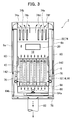
- FIG. 2 and 3 The internal structure of the solid oxide fuel cell (SOFC) device according to the embodiment of the present invention is explained using Figures 2 and 3 .
- a fuel cell assembly 12 As shown in Figures 2 and 3 , a fuel cell assembly 12, a reformer 20, and an air heat exchanger 22 are arranged in sequence starting from the bottom in the sealed space 8 within the fuel cell module 2 housing 6, as described above.
- a pure water guide pipe 60 for introducing pure water on the upstream end of the reformer 20, and a reform gas guide pipe 62 for introducing the fuel gas and reforming air to be reformed, are attached to the reformer 20; a vaporizing section 20a and a reforming section 20b are formed in sequence starting from the upstream side within the reformer 20, and the reforming section 20b is filled with a reforming catalyst. Fuel gas and air blended with the steam (pure water) introduced into the reformer 20 is reformed by the reforming catalyst used to fill in the reformer 20.
- Appropriate reforming catalysts are used, such as those in which nickel is imparted to the surface of alumina spheres, or ruthenium is imparted to alumina spheres.
- a fuel gas supply line 64 is connected to the downstream end of the reformer 20; this fuel gas supply line 64 extends downward, then further extends horizontally within a manifold formed under the fuel cell assembly 12.
- Multiple fuel supply holes 64b are formed on the bottom surface of a horizontal portion 64a of the fuel gas supply line 64; reformed fuel gas is supplied into the manifold 66 from these fuel supply holes 64b.
- a lower support plate 68 provided with through holes for supporting the above-described fuel cell stack 14 is attached at the top of the manifold 66, and fuel gas in the manifold 66 is supplied into the fuel cell unit 16.
- An air heat exchanger 22 is provided over the reformer 20.
- the air heat exchanger 22 is furnished with an air concentration chamber 70 on the upstream side and two air distribution chambers 72 on the downstream side; the air concentration chamber 70 and the distribution chambers 72 are connected using six air flow conduits 74.
- three air flow conduits 74 form a set (74a, 74b, 74c, 74d, 74e, 74f); air in the air concentration chamber 70 flows from each set of the air flow conduits 74 to the respective air distribution chambers 72.
- Air flowing in the six air flow conduits 74 of the air heat exchanger 22 is preheated by rising combustion exhaust gas from the combustion chamber 18.
- Air guide pipes 76 are connected to each of the respective air distribution chambers 72; these air guide pipes 76 extend downward, communicating at the bottom end side with the lower space in the generating chamber 10, and introducing preheated air into the generating chamber 10.
- an exhaust gas chamber 78 is formed below the manifold 66.
- an exhaust gas conduit 80 extending in the vertical direction is formed on the insides of the front surface 6a and the rear surface 6b which form the faces in the longitudinal direction of the housing 6; the top inside of the exhaust gas conduit 80 communicates with the space in which the air heat exchanger to rule 22 is disposed, and the bottom end side communicates with the exhaust gas chamber 78.
- An exhaust gas discharge pipe 82 is connected at approximately the center of the bottom surface of the exhaust gas chamber 78; the downstream end of the exhaust gas discharge pipe 82 is connected to the above-described hot water producing device 50 shown in Figure 1 . As shown in Fig.
- an ignition device 83 for starting the combustion of fuel gas and air is disposed on the combustion chamber 18.
- No heating means such as a burner or the like for separately heating the combustion chamber 18 or the fuel cell unit 16 to support ignition at startup or prevent flameout or blow out is provided on the combustion chamber 18.
- the fuel cell unit 16 is furnished with a fuel cell 84 and internal electrode terminals 86, respectively connected to the respective terminals at the top and bottom of the fuel cell 84.
- the fuel cell 84 is a tubular structure extending in the vertical direction, furnished with a cylindrical internal electrode layer 90, on the inside of which is formed a fuel gas flow path 88, a cylindrical external electrode layer 92, and an electrolyte layer 94 between the internal electrode layer 90 and the external electrode layer 92.
- the internal electrode layer 90 is a fuel electrode through which fuel gas passes, and is a (-) pole, while the external electrode layer 92 is an air electrode for contacting the air, and is a (+) pole.
- the internal electrode terminals 86 attached at the top and bottom ends of the fuel cell unit 16 have the same structure, therefore the internal electrode terminal 86 attached at the top end side will be specifically explained.
- the top portion 90a of the inside electrode layer 90 is furnished with an outside perimeter surface 90b and top end surface 90c, exposed to the electrolyte layer 94 and the outside electrode layer 92.
- the inside electrode terminal 86 is connected to the outer perimeter surface 90b of the inside electrode layer 90 through a conductive seal material 96, and is electrically connected to the inside electrode layer 90 by making direct contact with the top end surface 90c of the inside electrode layer 90.
- a fuel gas flow path 98 communicating with fuel gas flow path 88 in the inside electrode layer 90 is formed at the center portion of the inside electrode terminal 86.
- the inside electrode layer 90 is formed, for example, from at least one of a mixture of Ni and zirconia doped with at least one type of rare earth element selected from among Ca, Y, Sc, or the like; or a mixture of Ni and ceria doped with at least one type of rare earth element; or any mixture of Ni with lanthanum gallate doped with at least one element selected from among Sr, Mg, Co, Fe, or Cu.
- the electrolyte layer 94 is formed, for example, from at least one of the following: zirconia doped with at least one type of rare earth element selected from among Y, Sc, or the like; ceria doped with at least one type of selected rare earth element; or lanthanum gallate doped with at least one element selected from among Sr or Mg.
- the outside electrode layer 92 is formed, for example, from at least one of the following: lanthanum manganite doped with at least one element selected from among Sr or Ca; lanthanum ferrite doped with at least one element selected from among Sr, Co, Ni, or Cu; lanthanum cobaltite doped with at least one element selected from among Sr, Fe, Ni, or Cu; Ag, or the like.
- the fuel cell stack 14 As shown in Figure 5 , the fuel cell stack 14 is furnished with sixteen fuel cell units 16; the top sides and bottom sides of these fuel cell units 16 are respectively supported by a lower support plate 68 and upper support plate 100. Through holes 68a and 100a, through which the inside electrode terminal 86 can penetrate, are provided on the lower support plate 68 and upper support plate 100.
- a current collector 102 and an external terminal 104 are attached to the fuel cell unit 16.
- the current collector 102 is integrally formed by a fuel electrode connecting portion 102a, which is electrically connected to the inside electrode terminal 86 attached to the inside electrode layer 90 serving as the fuel electrode, and by an air electrode connecting portion 102b, which is electrically connected to the entire external perimeter of the outside electrode layer 92 serving as the air electrode.
- the air electrode connecting portion 102b is formed of a vertical portion 102c extending vertically along the surface of the outside electrode layer 92, and multiple horizontal portions 102d extending in the horizontal direction from the vertical portion 102c along the surface of the outside electrode layer 92.
- the fuel electrode connecting portion 102a extends linearly in an upward or downward diagonal direction from the vertical portion 102c of the air electrode connecting portion 102b toward the inside electrode terminals 86 positioned in the upper and lower directions on the fuel cell unit 16.
- inside electrode terminals 86 at the top and bottom ends of the two fuel cell units 16 positioned at the end of the fuel cell stack 14 (at the front and back sides on the left edge in Figure 5 ) are respectively connected to the external terminals 104.
- These external terminals 104 are connected to the external terminals 104 (not shown) at the ends of the adjacent fuel cell stack 14, and as described above, all of the 160 fuel cell units 16 are connected in series.
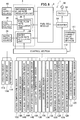
- a solid oxide fuel cell device 1 is furnished with a control unit 110, an operating device 112 provided with operating buttons such as "ON” or “OFF” for user operation, a display device 114 for displaying various data such as a generator output value (Watts), and a notification device 116 for issuing warnings during abnormal states and the like are connected to the control unit 110.
- the notification device 116 may be connected to a remote control center to inform the control center of abnormal states.
- a flammable gas detection sensor 120 detects gas leaks and is attached to the fuel cell module 2 and the auxiliary unit 4.
- the purpose of the flammable gas detection sensor 120 is to detect leakage of CO in the exhaust gas, which is meant to be exhausted to the outside via the exhaust gas conduit 80 and the like, into the external housing (not shown) which covers the fuel cell module 2 and the auxiliary unit 4.
- a water reservoir state detection sensor 124 detects the temperature and amount of hot water in a water heater (not shown).
- An electrical power state detection sensor 126 detects current, voltage, and the like in the inverter 54 and in a distribution panel (not shown).
- a power generating air flow rate detection sensor 128 detects the flow rate of power generating air supplied to the generating chamber 10.
- a reforming air flow rate sensor 130 detects the flow rate of reforming air supplied to the reformer 20.
- a fuel flow rate sensor 132 detects the flow rate of fuel gas supplied to the reformer 20.
- a water flow rate sensor 134 detects the flow rate of pure water (steam) supplied to the reformer 20.
- a water level sensor 136 detects the water level in pure water tank 26.
- a pressure sensor 138 detects pressure on the upstream side outside the reformer 20.
- An exhaust temperature sensor 140 detects the temperature of exhaust gas flowing into the hot water producing device 50.
- a generating chamber temperature sensor 142 is disposed on the front surface side and rear surface side around the fuel cell assembly 12, and detects the temperature around the fuel cell stack 14 in order to estimate the temperature of the fuel cell stack 14 (i.e., of the fuel cell 84 itself).
- a combustion chamber temperature sensor 144 detects the temperature in combustion chamber 18.
- An exhaust gas chamber temperature sensor 146 detects the temperature of exhaust gases in the exhaust gas chamber 78.
- a reformer temperature sensor 148 detects the temperature of the reformer 20 and calculates the reformer 20 temperature from the intake and exit temperatures on the reformer 20. If the solid oxide fuel cell (SOFC) device is placed outdoors, the outside temperature sensor 150 detects the temperature of the outside atmosphere. Sensors to detect outside atmospheric humidity and the like may also be provided.
- SOFC solid oxide fuel cell
- control unit 110 Signals from these various sensors are sent to the control unit 110; the control unit 110 sends control signals to the water flow rate regulator unit 28, the fuel flow rate regulator unit 38, the reforming air flow rate regulator unit 44, and the power generating air flow rate regulator unit 45 based on data from the sensors, and controls the flow rates in each of these units.
- the control unit 110 sends control signals to the inverter 54 to control the supplied electrical power.
- reforming air is supplied from the reforming air flow rate regulator unit 44 to the reformer 20 on the fuel cell module 2.
- power generating air is supplied from the generating air flow rate regulator unit 45 to an air heat exchanger 22 of the fuel cell module 2, and the power generating air reaches the generating chamber 10 and the combustion chamber 18.
- fuel gas is also supplied from the fuel flow rate regulator unit 38, and fuel gas into which reforming air is blended passes through the reformer 20, the fuel cell stack 14, and the fuel cell unit 16 to reach the combustion chamber 18.
- ignition is brought about by the ignition device 83, and fuel gas and air (reforming air and power generating air) supplied to the combustion chamber 18 is combusted.
- fuel gas and air reforming air and power generating air
- This combustion of fuel gas and air produces exhaust gas; the generating chamber 10 is warmed by the exhaust gas, and when the exhaust gas rises into the fuel cell module 2 sealed space 8, the fuel gas, which includes the reforming air in the reformer 20 is warm, as is the power generating air inside the air heat exchanger 22.
- This partial oxidation reforming reaction POX is an exothermic reaction, and therefore has favorable starting characteristics.
- the fuel gas whose temperature has risen is supplied from the fuel gas supply line 64 to the bottom of the fuel cell stack 14, and by this means the fuel cell stack 14 is heated from the bottom, and the temperature of the combustion chamber 18 has risen by the combustion of the fuel gas and air, and the fuel cell stack 14 is therefore heated from the upper side such that the temperature of the fuel cell stack 14 can be raised in an essentially uniform manner in the vertical direction. Even though the partial oxidation reforming reaction POX is progressing, the ongoing combustion reaction between fuel gas and air is continued in the combustion chamber 18.
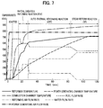
- the reformer temperature sensor 148 detects that the reformer 20 has reached a predetermined temperature (e.g. 600° C) after the start of the partial oxidation reforming reaction POX, a pre-blended gas of fuel gas, reforming air, and steam is applied to the reformer 20 by the water flow rate regulator unit 28, the fuel flow rate regulator unit 38, and the reforming air flow rate regulator unit 44.
- a predetermined temperature e.g. 600° C
- a pre-blended gas of fuel gas, reforming air, and steam is applied to the reformer 20 by the water flow rate regulator unit 28, the fuel flow rate regulator unit 38, and the reforming air flow rate regulator unit 44.
- an auto-thermal reforming reaction ATR which makes use of both the aforementioned partial oxidation reforming reaction POX and the steam reforming reaction SR described below, proceeds in the reformer 20.
- This auto-thermal reforming reaction ATR can be internally thermally balanced, therefore the reaction proceeds in a thermally independent fashion inside the reformer 20.
- the reformer temperature sensor 146 detects that the reformer 20 has reached a predetermined temperature (e.g., 700° C) following the start of the auto-thermal reforming reaction ATR shown as Expression (2), the supply of reforming air by the reforming air flow rate regulator unit 44 is stopped, and the supply of steam by the water flow rate regulator unit 28 is increased.
- a gas containing no air and only containing fuel gas and steam is supplied to the reformer 20, where the steam reforming reaction SR of Expression (3) proceeds.
- This steam reforming reaction SR is an endothermic reaction, therefore the reaction proceeds as a thermal balance is maintained with the heat of combustion from the combustion chamber 18.
- the fuel cell module 2 is in the final stages of startup, therefore the temperature has risen to a sufficiently high level within the generating chamber 10 so that no major temperature drop is induced in the power generating chamber 10 even though an endothermic reaction is proceeding.
- the combustion reaction continues to proceed in the combustion chamber 18 even as the steam reforming reaction SR is proceeding.
- the temperature inside the generating chamber 10 gradually rises as a result of the partial oxidation reforming reaction POX, the auto-thermal reforming reaction ATR, and the steam reforming reaction SR which proceed in that sequence.
- the circuit which includes the fuel cell module 2 is closed, power generation by the fuel cell module 2 begins, and current then flows to the circuit.
- Generation of electricity by the fuel cell module 2 causes the fuel cell 84 to emit heat, such that the temperature of the fuel cell 84 rises.
- the rated temperature at which the fuel cell module 2 is operated becomes, for example, 600°C - 800°C.
- the flow rate of power generating air supplied by the power generating air flow rate regulator unit 45 into the fuel cell module 2 is being increased at the same time that the flow rates of fuel gas and steam being supplied to the reformer 20 is being reduced; the fuel cell assembly 12 and the reformer 20 are air cooled to reduce their temperature. Thereafter, when the temperature of the generating chamber reaches a predetermined temperature, e.g. 400° C, supply of the fuel gas and steam to the reformer 20 is stopped, and the steam reforming reaction SR in the reformer 20 ends. Supply of the power generating air continues until the temperature in the reformer 20 reaches a predetermined temperature, e.g. 200° C; when the predetermined temperature is reached, the supply of power generating air from the power generating air flow rate regulator unit 45 is stopped.
- a predetermined temperature e.g. 400° C
- the steam reforming reaction SR by the reformer 20 and cooling by power generating air are used in combination, therefore when the operation of the fuel cell module 2 is stopped, that operation can be stopped relatively quickly.
- the solid oxide fuel cell device 1 of the present embodiment is disposed in a facility 56 such as a household or store, and the facility 56 is supplied with generated power from the inverter 54.
- This facility 56 is connected to a commercial power supply 58, and grid power is supplied from this commercial power supply 58.
- all or a portion of the demand power quantity required by the facility 56 is set as demand power P of the solid oxide fuel cell device 1, and power following operation is performed whereby the electrical generation output value is changed in response to this demand power P.
- the solid oxide fuel cell device 1 is furnished with a command current value setting section 111 for setting the command current value I S , which is the amount of current for the power to be generated by the solid oxide fuel cell device 1 based on the required power P of the solid oxide fuel cell device 1 as determined from the demand power required by the facility 56.
- the electrical power generated by the solid oxide fuel cell device 1 according to the present embodiment (the actual generated power) is controlled based on the demand power required by facilities 56 such as homes and the like (the total demand power), but if the demand power exceeds the maximum rated power which can be generated by the solid oxide fuel cell device 1, the missing portion is supplied by grid power (here, the portion representing the burden demanded of the solid oxide fuel cell device 1 out of the demand power is referred to as required power P (required load P)). Since demand power varies greatly with time, it is difficult for the power generated by the solid oxide fuel cell 1 to completely follow this demand power.
- the power generated by the solid oxide fuel cell device 1 (the fuel cell module 2) is controlled using as a target value a command power in which variation in required power P is kept down to a followable level.
- a command power in which variation in required power P is kept down to a followable level.
- time is required to actually generate electrical power within the fuel cell module 2, therefore a time delay arises the actual generated power extracted from the fuel cell module 2 after fuel is supplied, hence the inverter permitted power serving as permission signal, which is the permitted value for actually extracting power output to the inverter, is output by anticipating a time delay from the start of the supply of fuel.
- the solid oxide fuel cell device 1 operates so that the output voltage of the inverter 54 is a constant value 100V, therefore the above-described required power, maximum rated power, inverter permitted power, and actual generated power are respectively proportional to the required current, maximum rated current, inverter permitted current, and actual generated current. While the solid oxide fuel cell device 1 of the present embodiment is controlled based on these current values, the solid oxide fuel cell 1 may also be controlled in the same fashion, replacing "current" in the above with “power.” Note that, in the claims of the present invention, "power” is used in a broad meaning (command power, inverter permitted power, etc.) where reference is made to controlling current, and that this is not a description in which the interpretation is limited to current.
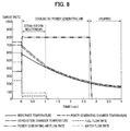
- Figure 9 is a timing chart showing the operating state during load following, when the electrical generating output value is changed in response to the demand power on the solid oxide fuel cell device 1 according to the embodiment of the present invention.
- the horizontal axis of the Figure 9 shows time, and the typical times at which the command current value I s changes are shown by times t1-t5.
- the vertical axis of Figure 9 shows in a time line from top to bottom as (i) - (iv) the processes by which, starting from the setting of required power P, the inverter permitted current I sinv permitting the extraction of the actual generated power P r is output at the inverter 54.
- the control section 110 sets the fuel supply amount F supplied to the reformer 20 in the fuel cell module 2 from the fuel flow regulator unit 38 based on the command current I s set by the command current value setting section 111.
- the fuel flow regulator unit 38 is controlled to increase or decrease the fuel supply rate F in accordance with the change in the command current I s , so that at least the command current I s can be output, and fuel is supplied to follow the required load.
- the actual fuel supply rate F r which is the actual measured value of the fuel supply rate supplied to the reformer 20 from the fuel flow regulator unit 38, is detected by a fuel flow rate sensor 132 (see Figure 9 "(iii) Actual Fuel Supply Rate F r ).
- control section 110 sets the generating air supply rate A supplied to the fuel cell assembly 12 in the fuel cell module 2 from the generating air flow regulator unit 45 based on the command current I s set in the command current value setting section 111, and on the previously detected actual fuel supply rate F r .
- control section 110 also sets the water supply rate W supplied to the reformer 20 in the fuel cell module 2 from the water flow regulator unit 28 based on the command current I s set in the command current value setting section 111 and on the previously detected actual fuel supply rate F r .
- the control section 110 permits the extraction of the actual generated power P r and sends an inverter permitted current I sinv control signal corresponding to the command current I s to the inverter 54, thereby controlling the power supply rate supplied to the facility 56.
- the inverter permitted current I sinv normally corresponds to a value for the current actually output from the fuel cell module 2 to the inverter 54 (actual generated current r ) (see Figure 9 "(iv) Inverter Permitted Current I sinv ").
- the amount of change per unit time in the inverter permitted current value I sinv commanded to the inverter 54 is changed based on the load status (described in detail below); that is, the system has been given the characteristic that a plurality of differing values for the amount of change per unit time are obtained for the inverter permitted current value, thus preventing fuel cell breakage associated with fuel depletion or air depletion, while saving energy by raising load following characteristics, thus increasing generated power from the fuel cell and reducing grid power from commercial power sources.
- the control section 110 thus changes the amount of change per unit time for the inverter permitted current value I sinv , and this changed inverter permitted current value I sinv per unit time is output to the inverter 54.
- control exercised by the control section 110 which changes the amount of change per unit time in the inverter permitted current value relative to the amount of load for load following by the solid oxide fuel cell device of the present embodiment will be described.
- Examples in which the amount of change per unit time in the inverter permitted current value is changed under various load conditions to increase load following performance and thereby improve energy saving performance will be described; these examples can be freely combined as needed.
- Example 1 of the control according to the present embodiment will be described, whereby the amount of change per unit time in the inverter permitted current value is changed.
- the amount of change per unit time in the inverter permitted current value (the inverter permitted current value change amount) is determined by the amount of change in load (load change amount) and the positive or negative the polarity state of the load change amount.
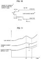
- the amount of change per unit time in the inverter permitted current value is set to be smaller when the amount of change in the load is small than when it is large. Specifically, when the amount of load change is small, it is set at 1 A/min (load change amount is positive), 1 A/min, and 3 A/min (load change amount is negative); and when the load change amount is large, it is set at 2A/min (load change amount is positive) and 5 A/min (load change amount is negative).
- the amounts of fuel and air supplied to the fuel cell module 2 can be increased, so that the fuel and air pressure fluctuation increases due to this increase in supply rate, thereby making the supply to each fuel cell 84 more uniform.
- the amount of change in the load is small, the fluctuation in fuel and air pressure is also small, making it difficult to supply each of the fuel cells 84 in a uniform manner.
- Example 1 of the present embodiment the amount of change per unit time in the next inverter permitted current value was changed to be a smaller value when the amount of change is load was small than when it was large, so that target amounts of fuel and air were not supplied in a portion of the fuel cells, and notwithstanding the partial insufficient state, the inverter extracted electrical power, thereby preventing the degradation or breakage of fuel cells.
- the amount of change per unit time in the inverter permitted current value (the inverter permitted current value change amount) is changed in both the case in which the load change amount is positive (load amount is increasing) and the case in which it is negative (load amount is decreasing)
- the amount of change per unit time in the inverter permitted current value (the inverter permitted current value change amount) is changed to a larger value when the load change amount is negative than when it is positive.
- Example 1 of the present embodiment when the amount of change per unit time in the inverter permitted current value from the past to the present is negative, i.e., when load decreases, the amount of change for the next inverter permitted current value is selected to have a proportionality characteristic whereby the amount of change per unit time is greater than when load increases, therefore when excessive fuel is being supplied relative to the target, the supply of fuel can be quickly reduced to the target value, thereby increasing fuel cell following performance and preventing unnecessary fuel waste.
- Example 1 of the present embodiment when the amount of change per unit time in the inverter permitted current value from the past to the present is positive, i.e.
- the amount of change per unit time in the inverter permitted current value is changed to a value which is smaller than when the load decreases, thereby enabling the suppression of problems arising from fuel cell module following delays, and reliably preventing the degradation and breakage of fuel cells arising from excessive extraction of current by the inverter.
- Example 2 of the control according to the present embodiment will be described, whereby the amount of change per unit time in the inverter permitted current value is changed.
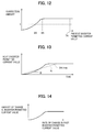
- the decrease in the amount of change per unit time in the inverter permitted current value is suppressed. Specifically, the amount of change per unit time in the inverter permitted current value is changed from the dotted line A to the solid line B.
- Example 2 of the present embodiment under those circumstances the amount of change per unit time in the next inverter permitted current value is changed so as to suppress a decrease in the amount of change in the next inverter permitted current value, thereby shortening the time needed to approach the target inverter permitted current value, resulting in an increase in generated power obtained from the fuel cell and a decrease in grid power obtained from commercial power supplies, thereby saving energy.
- Example 3 of the control according to the present embodiment will be described, whereby the amount of change per unit time in the inverter permitted current value is changed.
- the amount of change per unit time in the next inverter permitted current value is changed (corrected) to a larger value when the present inverter permitted current value is large than when that value is small.
- the correction amount of the change amount per unit time in the inverter permitted current value increases with the size of the inverter permitted current value; in the region in which the present inverter permitted current value is 3A or greater, the amount of correction is a fixed value.
- the correction amount is "1 ".
- Figure 13 shows the next inverter permitted current value by changing the amount of change per unit time in the present inverter permitted current value.
- Figure 13 shows an example in which the amount of change per unit time in the next inverter permitted current value changed from the present inverter permitted current value is 2 A/min; this change amount is shown by the dotted line A; in actuality, response is as shown by the solid line B.
- Example 3 of the present embodiment the generating reaction is occurring and the fuel cells are stable at a high temperature when the inverter permitted current value has a large value, i.e., when the amount of power generated by the present fuel cell module 2 is high, therefore negative effects on the fuel cells can be suppressed even when the amount of change per unit time when changing the present inverter permitted current value to the next inverter permitted current value is changed to a greater value when the present inverter permitted current value is large than when it is small in order to increase following sensitivity.
- Example 4 of the control according to the present embodiment will be described, whereby the amount of change per unit time in the inverter permitted current value is changed.
- the amount of change per unit time in the inverter permitted current value is changed based on the status of the past inverter permitted current value. In other words, when the past inverter permitted current value is increasing and the next inverter permitted current value will also increase, the larger amount of change per unit time in the next inverter permitted current value is changed to increase, the larger the past inverter permitted current value rate of change was. It is preferable to use the average value of the differential in inverter permitted current values over the last 5 times, for example, as the past inverter permitted current value state. An average value for the last 5 times of the inverter permitted current value itself may also be used.
- Example 4 of the present embodiment when the past inverter permitted current value is increasing and the next inverter permitted current value is also increasing, a change is made so that the larger amount of change per unit time in the next inverter permitted current value increases, the larger the amount of change per unit time in the past inverter permitted current value is, so following performance can be increased and energy savings improved, while negative effects on the fuel cells are suppressed.
- Example 5 of the control according to the present embodiment will be described, whereby the amount of change per unit time in the inverter permitted current value is changed.
- the amount of change per unit time in the present inverter permitted current value is changed (corrected) to be more greater, the larger the deviation relative to the target inverter permitted current value is.
- the correction amount of the change amount per unit time in the inverter permitted current value increases with the size of the inverter permitted current value deviation, and in the region in which the present inverter permitted current value deviation is 2 A or greater, the amount of correction is a fixed value.
- the inverter permitted current value deviation is 1.5A, the correction amount is "1".
- Example 5 of the embodiment the amount of change per unit time in the present inverter permitted current value is changed (corrected) so as to be large to the degree that the deviation of the present inverter permitted current value is large relative to the target inverter permitted current value, therefore following performance can be improved. Furthermore, in the convergence process in which the deviation is reduced, the amount of change per unit time in the inverter permitted current value slowly reaches the target inverter permitted current value, therefore fuel depletion can be reliably prevented.
- Example 6 of the control according to the present embodiment will be described, whereby the amount of change per unit time in the inverter permitted current value is changed.
- proportionality characteristics indicating the amount of change per unit time for three different inverter permitted current values are prepared (set) ahead of time; one of these proportionality characteristics is selected according to the amount of change in load (load change amount), and the amount of change per unit time in inverter permitted current value is changed according to this selected proportionality characteristic.
- a 3 A/min proportionality characteristic B1 for the inverter permitted current value amount of change per unit time when the load change amount is large a 2 A/min proportionality characteristic B2 for the inverter permitted current value amount of change per unit time when the load change amount is medium, and a 1 A/min proportionality characteristic B3 for the inverter permitted current value amount of change per unit time when the load change amount is small; one of these proportionality characteristics is selected according to the size of the load change amount.
- Example 6 three different proportionality characteristics indicating the inverter permitted current value amount of change per unit time are prepared ahead of time; one of these three proportionality characteristics is selected based on the state of the load, and the next inverter permitted current value amount of change per unit time is changed by using this selected proportionality characteristic, thus simplifying fuel cell control and stabilizing changes in the inverter permitted current value with respect to the changing load state; as a result, fuel supply, air supply, and the reformer reaction can be stabilized.
- Example 7 of the control according to the present embodiment will be described, whereby the amount of change per unit time in the inverter permitted current value is changed.
- the amount of change per unit time in the inverter permitted current value is kept down even when the load amount changes greatly, thereby enabling a stabilization of fuel, air, and reform reaction.
- Example 8 of the control according to the present embodiment will be described, whereby the amount of change per unit time in the inverter permitted current value is changed.
- three different proportionality characteristics for the deviation in the present inverter permitted current value relative to the target inverter permitted current value are prepared (set); one of these proportionality characteristics is selected based on the amount of the deviation, and the amount of change per unit time in the present inverter permitted current value is changed according to this selected proportionality characteristic.
- control may also be exercised simultaneously with the above-described Examples 1 through 8. That is, it is also acceptable to vary the fuel supply rate supplied in response to the amount of change per unit time in the deviation of the present inverter permitted current value relative to the target inverter permitted current value while simultaneously changing the amount of change per unit time in the deviation of the present inverter permitted current value relative to the target inverter permitted current value.
- the amount of fuel supplied is varied in response to the amount of change per unit time in the inverter permitted current value at the same time that the amount of change per unit time in the inverter permitted current value is being changed, thereby enabling increased load following characteristics while also greatly increasing the reliability of fuel cells.
- the control (Example 1) for changing the amount of change per unit time in the inverter permitted current value by using the "reformer temperature," which is a predetermined parameter, by means of the inverter permitted current value change means of the second embodiment.
- the reformer temperature transitions from a low temperature region at which the reform reaction starts to a stable high temperature region at which the reforming reaction is carried out.
- the reformer temperature also goes into an anomalous high temperature region at a temperature above the stable high temperature region.
- the amount of change per unit time in the inverter permitted current value is first changed (corrected) based on this reformer temperature state.
- the amount of change per unit time in the inverter permitted current value is changed (corrected) based on the temperature of the reformer, which indicates changes in the reforming reaction, therefore the amount of change per unit time in the inverter permitted current value (the rate of change) can be optimized by absorbing changes in the reformer reforming reaction, thereby increasing fuel cell reliability and energy saving performance.
- the reformer temperature is in a low temperature region when the reformer temperature is below A°C, and is therefore changed (corrected) so that the amount of correction is less than "1", and the amount of change per unit time in the inverter permitted current value becomes small.
- the reformer temperature is between A°C and C°C, the reformer temperature is in a high temperature region state, therefore a change (correction) is made so that the amount of correction is greater than "1", and the amount of change per unit time in the inverter permitted current value is large.
- the fuel cell device when the reformer temperature is between B°C and C°C, the fuel cell device is in a stable high temperature region, therefore the amount of correction applied to the change amount per unit time in the command current value is fixed or constant.
- the reformer temperature when the reformer temperature is in a temperature region below the first predetermined temperature (the reformer temperature is B°C), the amount of change per unit time in the inverter permitted current value is changed (corrected) to be larger to the extent that the reformer temperature increases.
- Example 1 of the second embodiment when the reformer is in a temperature region below the second predetermined temperature (the reformer temperature is C°C), the reforming reaction in the reformer is in a stable state at a high temperature state in which the reformer temperature is between A°C and C°C, therefore a correction is made so that the amount of change per unit time in the inverter permitted current value becomes large, thereby increasing load following performance.
- the amount of change per unit time in the inverter permitted current value is changed (corrected) to be small, such that fuel cell reliability can be assured while energy saving performance is improved.
- Example 2 of the second embodiment if it is determined that the reformer temperature is in the anomalous high temperature region above the second predetermined temperature (the reformer temperature is C°C), a correction is made to make the amount of change per unit time in the command current value small.
- the reformer temperature when the reformer temperature is in the anomalous high temperature region, there is a possibility of reformer anomalies or fuel cell anomalies (degradation), hence the amount of change per unit time in the inverter permitted current value was changed (corrected) to become small, preventing further degradation of the fuelcells and improving reliability improved while assuring energy saving performance.
- the amount of change per unit time in the inverter permitted current value is first changed (corrected) and the inverter permitted current value changed (corrected) based on the fuel cell stack temperature state.
- the amount of change per unit time in the inverter permitted current value is changed (corrected) based on the temperature state of the fuel cell stack, which indicates changes in the generating reaction, therefore the inverter permitted power value can be optimized using the temperature state of the fuel cell stack generating reaction, thereby increasing fuel cell reliability and energy saving performance.
- Example 2 when the fuel cell stack temperature is in a temperature region equal to or lower than the first predetermined temperature (the fuel cell stack temperature is E°C), the amount of change per unit time in the inverter permitted current value is changed (corrected) to be larger, the higher the reformer temperature is.
- the generating reaction in the fuel cell stack is stable when the fuel cell stack is in a high temperature region within the temperature region equal to or lower than a predetermined temperature (the fuel cell stack temperature is E°C), and the amount of change per unit time in the inverter permitted power value can be changed (corrected) to be large to increase load following performance, resulting in an improvement in energy saving performance while assuring fuel cell reliability.
- Example 2 of the second embodiment if it is determined that the fuel cell stack temperature is in the anomalous high temperature region above the second predetermined temperature (the fuel cell stack temperature is F°C), a change (correction) is made to make the amount of change per unit time in the inverter permitted current value small.
- Example 2 of the second embodiment the possibility can be conceived of anomalies (degradation) in the fuel cells if the fuel cell stack temperature enters an anomalous high temperature region above the second predetermined temperature, and of a drop in oxygen concentration occurring when generating air supplied to the fuel cell stack expands beyond the normal level but the amount of oxygen contained in that air does not change, thus decreasing the amount of oxygen supplied to the fuel cells and consequently decreasing the amount of oxygen capable of being involved in electrical generation; in such cases the amount of change per unit time in the inverter permitted current value is changed (corrected) to be small, thereby increasing reliability of the fuel cells while assuring energy savings.
- anomalies degradation
- Example 3 the control (Example 3) for changing the amount of change per unit time in the inverter permitted current value using "outside air temperature", which is a predetermined parameter, by means of the second command current value change means of the second embodiment will be described.
- the amount of change per unit time in the inverter permitted current value is changed (corrected) to be smaller, the higher that the outside air temperature is.
- Example 3 of the second embodiment it is conceivable that when the outside air temperature is low, temperature changes in the space around the fuel cell stack will be small, and that steam production in the reformer will be diminished, so a correction is made to follow such a state and keep the amount of change per unit time in the inverter permitted current value small, thereby increasing energy saving performance and fuel cell reliability.
- the control for changing the amount of change per unit time in the inverter permitted current value by using "fuel cell anomaly," which is a predetermined parameter, by means of the inverter permitted current value change means of the second embodiment.
- the fuel cells degrade with long years of use, so when these fuel cells become degraded, a determination of an anomalous condition is made.
- the fuel cell operating state can be stabilized by maintaining supply rates of fuel gas, generating air, and water to the fuel cells at a level corresponding to the maximum rated generating power output (e.g., 700W); if the generating chamber temperature is above a predetermined temperature after stabilizing, a determination is made that degradation has occurred.
- a determination of an anomalous fuel cell state is also made for a clogged filter or the like.
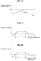
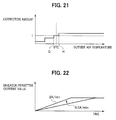
- Example 4 of the second embodiment when a determination is made that a fuel cell is abnormal, a change (correction) from 2 A/min to 0. 5 A/min is specifically made so that the amount of change per unit time in the inverter permitted current value is made small, as shown in Figure 21 .
- a change (correction) when a determination is made of an abnormal fuel cell due to fuel cell degradation or filter clogging or the like, a change (correction) is made so that the amount of change per unit time in the inverter permitted current value becomes small, and the inverter permitted current value is lowered, so fuel cell reliability can be increased while improving energy saving performance.
- This third embodiment combines the above-described first inverter permitted current value change means of the first embodiment and second inverter permitted current value change means of the second embodiment. Specifically, the amount of change per unit time in the inverter permitted current value is changed according to load amount by the first inverter permitted current value change means, then the amount of change per unit time in the inverter permitted current value changed by the first inverter permitted current value change means is further changed according to predetermined parameters by the second inverter permitted current value change means.
- the amount of change per unit time in the inverter permitted current value is first changed according to load amount by using the first inverter permitted current value change means, then a judgment is made of the conditions in which changes in the generating reaction or the reforming reaction arise when using the second inverter permitted current value change means, and the amount of change per unit time in the inverter permitted current value is further changed, therefore control sensitivity can be increased by the provision of the first inverter permitted current value change means for optimally changing the amount of change per unit time in the inverter permitted current value according to load amount; moreover, the inverter permitted current value is also changed according to parameters other than load, making it possible to assure reliability of the fuel cells so that load following performance is safely increased.
Landscapes
- Life Sciences & Earth Sciences (AREA)
- Engineering & Computer Science (AREA)
- Manufacturing & Machinery (AREA)
- Sustainable Development (AREA)
- Sustainable Energy (AREA)
- Chemical & Material Sciences (AREA)
- Chemical Kinetics & Catalysis (AREA)
- Electrochemistry (AREA)
- General Chemical & Material Sciences (AREA)
- Fuel Cell (AREA)
Applications Claiming Priority (1)
| Application Number | Priority Date | Filing Date | Title |
|---|---|---|---|
| JP2009228733A JP5391976B2 (ja) | 2009-09-30 | 2009-09-30 | 固体電解質型燃料電池 |
Publications (2)
| Publication Number | Publication Date |
|---|---|
| EP2306573A1 true EP2306573A1 (de) | 2011-04-06 |
| EP2306573B1 EP2306573B1 (de) | 2012-06-27 |
Family
ID=43416853
Family Applications (1)
| Application Number | Title | Priority Date | Filing Date |
|---|---|---|---|
| EP10181370A Not-in-force EP2306573B1 (de) | 2009-09-30 | 2010-09-28 | Festoxid-Brennstoffzellenvorrichtung |
Country Status (4)
| Country | Link |
|---|---|
| US (2) | US20110076577A1 (de) |
| EP (1) | EP2306573B1 (de) |
| JP (1) | JP5391976B2 (de) |
| CN (1) | CN102035005B (de) |
Cited By (1)
| Publication number | Priority date | Publication date | Assignee | Title |
|---|---|---|---|---|
| EP2800185A4 (de) * | 2011-12-28 | 2015-06-17 | Panasonic Corp | Brennstoffzellensystem und betriebsverfahren dafür |
Families Citing this family (6)
| Publication number | Priority date | Publication date | Assignee | Title |
|---|---|---|---|---|
| DK2541722T3 (en) * | 2011-06-29 | 2016-01-11 | Siemens Ag | A method and controller for controlling a device for producing electrical power, in particular a wind turbine |
| WO2013061513A1 (ja) * | 2011-10-24 | 2013-05-02 | パナソニック株式会社 | 燃料電池システム及びその運転方法 |
| CN102520613A (zh) * | 2011-12-30 | 2012-06-27 | 西南交通大学 | 基于最优过氧比的质子交换膜燃料电池系统二自由度控制方法 |
| JP6154256B2 (ja) * | 2013-09-10 | 2017-06-28 | 京セラ株式会社 | 燃料電池システム及び燃料電池システムの運転方法 |
| WO2015179208A1 (en) | 2014-05-20 | 2015-11-26 | Koninklijke Philips N.V. | Intravascular devices, systems, and methods having drive cables with a lubricious coating and/or radiopaque markers |
| JP6749799B2 (ja) * | 2016-06-27 | 2020-09-02 | 三菱日立パワーシステムズ株式会社 | 燃料電池の制御装置及び制御方法並びに発電システム |
Citations (4)
| Publication number | Priority date | Publication date | Assignee | Title |
|---|---|---|---|---|
| JPH07307163A (ja) | 1994-05-13 | 1995-11-21 | Tokyo Gas Co Ltd | 燃料電池発電装置の負荷制御装置 |
| US6379826B1 (en) * | 1999-11-18 | 2002-04-30 | Plug Power Inc. | Regulating a fuel cell powered heating system |
| US20050042488A1 (en) * | 2003-08-19 | 2005-02-24 | Quantum Technologies | Transportable solid oxide fuel cell generator |
| JP2007220620A (ja) | 2006-02-20 | 2007-08-30 | Sanyo Electric Co Ltd | 燃料電池発電装置 |
Family Cites Families (7)
| Publication number | Priority date | Publication date | Assignee | Title |
|---|---|---|---|---|
| JP3744341B2 (ja) * | 2000-11-02 | 2006-02-08 | 日産自動車株式会社 | 改質反応器の制御装置 |
| WO2003105261A1 (ja) * | 2002-05-15 | 2003-12-18 | 松下電器産業株式会社 | 燃料電池発電装置 |
| JP2006032262A (ja) * | 2004-07-21 | 2006-02-02 | Tokyo Gas Co Ltd | 燃料電池システム及び制御方法 |
| JP4767543B2 (ja) * | 2005-01-07 | 2011-09-07 | Jx日鉱日石エネルギー株式会社 | 固体酸化物形燃料電池システムの起動方法 |
| JP5258180B2 (ja) * | 2006-09-28 | 2013-08-07 | 京セラ株式会社 | 固体電解質形燃料電池システム |
| JP5081574B2 (ja) * | 2007-10-23 | 2012-11-28 | 本田技研工業株式会社 | 燃料電池システムの負荷増加時の運転方法 |
| JP4702708B2 (ja) * | 2009-09-30 | 2011-06-15 | Toto株式会社 | 固体電解質型燃料電池 |
-
2009
- 2009-09-30 JP JP2009228733A patent/JP5391976B2/ja not_active Expired - Fee Related
-
2010
- 2010-09-28 EP EP10181370A patent/EP2306573B1/de not_active Not-in-force
- 2010-09-29 CN CN2010105003614A patent/CN102035005B/zh not_active Expired - Fee Related
- 2010-09-29 US US12/893,456 patent/US20110076577A1/en not_active Abandoned
-
2014
- 2014-04-24 US US14/260,699 patent/US20140234736A1/en not_active Abandoned
Patent Citations (4)
| Publication number | Priority date | Publication date | Assignee | Title |
|---|---|---|---|---|
| JPH07307163A (ja) | 1994-05-13 | 1995-11-21 | Tokyo Gas Co Ltd | 燃料電池発電装置の負荷制御装置 |
| US6379826B1 (en) * | 1999-11-18 | 2002-04-30 | Plug Power Inc. | Regulating a fuel cell powered heating system |
| US20050042488A1 (en) * | 2003-08-19 | 2005-02-24 | Quantum Technologies | Transportable solid oxide fuel cell generator |
| JP2007220620A (ja) | 2006-02-20 | 2007-08-30 | Sanyo Electric Co Ltd | 燃料電池発電装置 |
Cited By (1)
| Publication number | Priority date | Publication date | Assignee | Title |
|---|---|---|---|---|
| EP2800185A4 (de) * | 2011-12-28 | 2015-06-17 | Panasonic Corp | Brennstoffzellensystem und betriebsverfahren dafür |
Also Published As
| Publication number | Publication date |
|---|---|
| EP2306573B1 (de) | 2012-06-27 |
| CN102035005A (zh) | 2011-04-27 |
| JP5391976B2 (ja) | 2014-01-15 |
| JP2011076943A (ja) | 2011-04-14 |
| US20140234736A1 (en) | 2014-08-21 |
| CN102035005B (zh) | 2013-07-10 |
| US20110076577A1 (en) | 2011-03-31 |
Similar Documents
| Publication | Publication Date | Title |
|---|---|---|
| US8426074B2 (en) | Solid oxide fuel cell | |
| EP2312679B1 (de) | Festoxid-Brennstoffzellenvorrichtung | |
| EP2416418B1 (de) | Festelektrolyt-brennstoffzelle | |
| EP2264821B1 (de) | Festoxid-Brennstoffzellenvorrichtung | |
| EP2256847B1 (de) | Festoxid-Brennstoffzellenvorrichtung | |
| EP2306575B1 (de) | Festoxid-Brennstoffzellenvorrichtung | |
| EP2624346A1 (de) | Brennstoffzellenelement | |
| EP2256849B1 (de) | Festoxid-Brennstoffzellenvorrichtung | |
| EP2306573B1 (de) | Festoxid-Brennstoffzellenvorrichtung | |
| US8492041B2 (en) | Solid oxide fuel cell | |
| EP2256848B1 (de) | Festoxid-Brennstoffzellenvorrichtung | |
| EP2306574B1 (de) | Festoxid-Brennstoffzellenvorrichtung | |
| US8859156B2 (en) | Solid oxide fuel cell | |
| EP2416422B1 (de) | Festelektrolyt-brennstoffzelle | |
| EP2416426B1 (de) | Festelektrolyt-brennstoffzelle | |
| EP2645462B1 (de) | Festoxidbrennstoffzellensystem | |
| JP2011076942A (ja) | 固体電解質型燃料電池 |
Legal Events
| Date | Code | Title | Description |
|---|---|---|---|
| PUAI | Public reference made under article 153(3) epc to a published international application that has entered the european phase |
Free format text: ORIGINAL CODE: 0009012 |
|
| AK | Designated contracting states |
Kind code of ref document: A1 Designated state(s): AL AT BE BG CH CY CZ DE DK EE ES FI FR GB GR HR HU IE IS IT LI LT LU LV MC MK MT NL NO PL PT RO SE SI SK SM TR |
|
| AX | Request for extension of the european patent |
Extension state: BA ME RS |
|
| 17P | Request for examination filed |
Effective date: 20110930 |
|
| GRAP | Despatch of communication of intention to grant a patent |
Free format text: ORIGINAL CODE: EPIDOSNIGR1 |
|
| GRAS | Grant fee paid |
Free format text: ORIGINAL CODE: EPIDOSNIGR3 |
|
| GRAA | (expected) grant |
Free format text: ORIGINAL CODE: 0009210 |
|
| AK | Designated contracting states |
Kind code of ref document: B1 Designated state(s): AL AT BE BG CH CY CZ DE DK EE ES FI FR GB GR HR HU IE IS IT LI LT LU LV MC MK MT NL NO PL PT RO SE SI SK SM TR |
|
| REG | Reference to a national code |
Ref country code: GB Ref legal event code: FG4D |
|
| REG | Reference to a national code |
Ref country code: CH Ref legal event code: EP |
|
| REG | Reference to a national code |
Ref country code: AT Ref legal event code: REF Ref document number: 564611 Country of ref document: AT Kind code of ref document: T Effective date: 20120715 |
|
| REG | Reference to a national code |
Ref country code: IE Ref legal event code: FG4D |
|
| REG | Reference to a national code |
Ref country code: DE Ref legal event code: R096 Ref document number: 602010002022 Country of ref document: DE Effective date: 20120823 |
|
| PG25 | Lapsed in a contracting state [announced via postgrant information from national office to epo] |
Ref country code: FI Free format text: LAPSE BECAUSE OF FAILURE TO SUBMIT A TRANSLATION OF THE DESCRIPTION OR TO PAY THE FEE WITHIN THE PRESCRIBED TIME-LIMIT Effective date: 20120627 Ref country code: SE Free format text: LAPSE BECAUSE OF FAILURE TO SUBMIT A TRANSLATION OF THE DESCRIPTION OR TO PAY THE FEE WITHIN THE PRESCRIBED TIME-LIMIT Effective date: 20120627 Ref country code: LT Free format text: LAPSE BECAUSE OF FAILURE TO SUBMIT A TRANSLATION OF THE DESCRIPTION OR TO PAY THE FEE WITHIN THE PRESCRIBED TIME-LIMIT Effective date: 20120627 Ref country code: NO Free format text: LAPSE BECAUSE OF FAILURE TO SUBMIT A TRANSLATION OF THE DESCRIPTION OR TO PAY THE FEE WITHIN THE PRESCRIBED TIME-LIMIT Effective date: 20120927 |
|
| REG | Reference to a national code |
Ref country code: NL Ref legal event code: VDEP Effective date: 20120627 |
|
| REG | Reference to a national code |
Ref country code: AT Ref legal event code: MK05 Ref document number: 564611 Country of ref document: AT Kind code of ref document: T Effective date: 20120627 |
|
| RAP2 | Party data changed (patent owner data changed or rights of a patent transferred) |
Owner name: TOTO LTD. |
|
| REG | Reference to a national code |
Ref country code: LT Ref legal event code: MG4D Effective date: 20120627 |
|
| PG25 | Lapsed in a contracting state [announced via postgrant information from national office to epo] |
Ref country code: HR Free format text: LAPSE BECAUSE OF FAILURE TO SUBMIT A TRANSLATION OF THE DESCRIPTION OR TO PAY THE FEE WITHIN THE PRESCRIBED TIME-LIMIT Effective date: 20120627 Ref country code: GR Free format text: LAPSE BECAUSE OF FAILURE TO SUBMIT A TRANSLATION OF THE DESCRIPTION OR TO PAY THE FEE WITHIN THE PRESCRIBED TIME-LIMIT Effective date: 20120928 Ref country code: SI Free format text: LAPSE BECAUSE OF FAILURE TO SUBMIT A TRANSLATION OF THE DESCRIPTION OR TO PAY THE FEE WITHIN THE PRESCRIBED TIME-LIMIT Effective date: 20120627 Ref country code: LV Free format text: LAPSE BECAUSE OF FAILURE TO SUBMIT A TRANSLATION OF THE DESCRIPTION OR TO PAY THE FEE WITHIN THE PRESCRIBED TIME-LIMIT Effective date: 20120627 |
|
| PG25 | Lapsed in a contracting state [announced via postgrant information from national office to epo] |
Ref country code: SK Free format text: LAPSE BECAUSE OF FAILURE TO SUBMIT A TRANSLATION OF THE DESCRIPTION OR TO PAY THE FEE WITHIN THE PRESCRIBED TIME-LIMIT Effective date: 20120627 Ref country code: AT Free format text: LAPSE BECAUSE OF FAILURE TO SUBMIT A TRANSLATION OF THE DESCRIPTION OR TO PAY THE FEE WITHIN THE PRESCRIBED TIME-LIMIT Effective date: 20120627 Ref country code: CY Free format text: LAPSE BECAUSE OF FAILURE TO SUBMIT A TRANSLATION OF THE DESCRIPTION OR TO PAY THE FEE WITHIN THE PRESCRIBED TIME-LIMIT Effective date: 20120627 Ref country code: IS Free format text: LAPSE BECAUSE OF FAILURE TO SUBMIT A TRANSLATION OF THE DESCRIPTION OR TO PAY THE FEE WITHIN THE PRESCRIBED TIME-LIMIT Effective date: 20121027 Ref country code: EE Free format text: LAPSE BECAUSE OF FAILURE TO SUBMIT A TRANSLATION OF THE DESCRIPTION OR TO PAY THE FEE WITHIN THE PRESCRIBED TIME-LIMIT Effective date: 20120627 Ref country code: BE Free format text: LAPSE BECAUSE OF FAILURE TO SUBMIT A TRANSLATION OF THE DESCRIPTION OR TO PAY THE FEE WITHIN THE PRESCRIBED TIME-LIMIT Effective date: 20120627 Ref country code: RO Free format text: LAPSE BECAUSE OF FAILURE TO SUBMIT A TRANSLATION OF THE DESCRIPTION OR TO PAY THE FEE WITHIN THE PRESCRIBED TIME-LIMIT Effective date: 20120627 Ref country code: CZ Free format text: LAPSE BECAUSE OF FAILURE TO SUBMIT A TRANSLATION OF THE DESCRIPTION OR TO PAY THE FEE WITHIN THE PRESCRIBED TIME-LIMIT Effective date: 20120627 |
|
| PG25 | Lapsed in a contracting state [announced via postgrant information from national office to epo] |
Ref country code: PL Free format text: LAPSE BECAUSE OF FAILURE TO SUBMIT A TRANSLATION OF THE DESCRIPTION OR TO PAY THE FEE WITHIN THE PRESCRIBED TIME-LIMIT Effective date: 20120627 Ref country code: PT Free format text: LAPSE BECAUSE OF FAILURE TO SUBMIT A TRANSLATION OF THE DESCRIPTION OR TO PAY THE FEE WITHIN THE PRESCRIBED TIME-LIMIT Effective date: 20121029 Ref country code: IT Free format text: LAPSE BECAUSE OF FAILURE TO SUBMIT A TRANSLATION OF THE DESCRIPTION OR TO PAY THE FEE WITHIN THE PRESCRIBED TIME-LIMIT Effective date: 20120627 |
|
| PG25 | Lapsed in a contracting state [announced via postgrant information from national office to epo] |
Ref country code: NL Free format text: LAPSE BECAUSE OF FAILURE TO SUBMIT A TRANSLATION OF THE DESCRIPTION OR TO PAY THE FEE WITHIN THE PRESCRIBED TIME-LIMIT Effective date: 20120627 |
|
| PG25 | Lapsed in a contracting state [announced via postgrant information from national office to epo] |
Ref country code: ES Free format text: LAPSE BECAUSE OF FAILURE TO SUBMIT A TRANSLATION OF THE DESCRIPTION OR TO PAY THE FEE WITHIN THE PRESCRIBED TIME-LIMIT Effective date: 20121008 Ref country code: DK Free format text: LAPSE BECAUSE OF FAILURE TO SUBMIT A TRANSLATION OF THE DESCRIPTION OR TO PAY THE FEE WITHIN THE PRESCRIBED TIME-LIMIT Effective date: 20120627 Ref country code: MC Free format text: LAPSE BECAUSE OF NON-PAYMENT OF DUE FEES Effective date: 20120930 |
|
| PLBE | No opposition filed within time limit |
Free format text: ORIGINAL CODE: 0009261 |
|
| STAA | Information on the status of an ep patent application or granted ep patent |
Free format text: STATUS: NO OPPOSITION FILED WITHIN TIME LIMIT |
|
| 26N | No opposition filed |
Effective date: 20130328 |
|
| REG | Reference to a national code |
Ref country code: IE Ref legal event code: MM4A |
|
| REG | Reference to a national code |
Ref country code: FR Ref legal event code: ST Effective date: 20130531 |
|
| REG | Reference to a national code |
Ref country code: DE Ref legal event code: R097 Ref document number: 602010002022 Country of ref document: DE Effective date: 20130328 |
|
| PG25 | Lapsed in a contracting state [announced via postgrant information from national office to epo] |
Ref country code: IE Free format text: LAPSE BECAUSE OF NON-PAYMENT OF DUE FEES Effective date: 20120928 Ref country code: BG Free format text: LAPSE BECAUSE OF FAILURE TO SUBMIT A TRANSLATION OF THE DESCRIPTION OR TO PAY THE FEE WITHIN THE PRESCRIBED TIME-LIMIT Effective date: 20120927 |
|
| PG25 | Lapsed in a contracting state [announced via postgrant information from national office to epo] |
Ref country code: FR Free format text: LAPSE BECAUSE OF NON-PAYMENT OF DUE FEES Effective date: 20121001 |
|
| PG25 | Lapsed in a contracting state [announced via postgrant information from national office to epo] |
Ref country code: AL Free format text: LAPSE BECAUSE OF FAILURE TO SUBMIT A TRANSLATION OF THE DESCRIPTION OR TO PAY THE FEE WITHIN THE PRESCRIBED TIME-LIMIT Effective date: 20120627 Ref country code: MT Free format text: LAPSE BECAUSE OF FAILURE TO SUBMIT A TRANSLATION OF THE DESCRIPTION OR TO PAY THE FEE WITHIN THE PRESCRIBED TIME-LIMIT Effective date: 20120627 |
|
| PG25 | Lapsed in a contracting state [announced via postgrant information from national office to epo] |
Ref country code: TR Free format text: LAPSE BECAUSE OF FAILURE TO SUBMIT A TRANSLATION OF THE DESCRIPTION OR TO PAY THE FEE WITHIN THE PRESCRIBED TIME-LIMIT Effective date: 20120627 |
|
| PG25 | Lapsed in a contracting state [announced via postgrant information from national office to epo] |
Ref country code: LU Free format text: LAPSE BECAUSE OF NON-PAYMENT OF DUE FEES Effective date: 20120928 Ref country code: SM Free format text: LAPSE BECAUSE OF FAILURE TO SUBMIT A TRANSLATION OF THE DESCRIPTION OR TO PAY THE FEE WITHIN THE PRESCRIBED TIME-LIMIT Effective date: 20120627 |
|
| PG25 | Lapsed in a contracting state [announced via postgrant information from national office to epo] |
Ref country code: HU Free format text: LAPSE BECAUSE OF FAILURE TO SUBMIT A TRANSLATION OF THE DESCRIPTION OR TO PAY THE FEE WITHIN THE PRESCRIBED TIME-LIMIT Effective date: 20100928 |
|
| REG | Reference to a national code |
Ref country code: CH Ref legal event code: PL |
|
| GBPC | Gb: european patent ceased through non-payment of renewal fee |
Effective date: 20140928 |
|
| PG25 | Lapsed in a contracting state [announced via postgrant information from national office to epo] |
Ref country code: GB Free format text: LAPSE BECAUSE OF NON-PAYMENT OF DUE FEES Effective date: 20140928 Ref country code: LI Free format text: LAPSE BECAUSE OF NON-PAYMENT OF DUE FEES Effective date: 20140930 Ref country code: CH Free format text: LAPSE BECAUSE OF NON-PAYMENT OF DUE FEES Effective date: 20140930 Ref country code: MK Free format text: LAPSE BECAUSE OF FAILURE TO SUBMIT A TRANSLATION OF THE DESCRIPTION OR TO PAY THE FEE WITHIN THE PRESCRIBED TIME-LIMIT Effective date: 20120627 |
|
| PGFP | Annual fee paid to national office [announced via postgrant information from national office to epo] |
Ref country code: DE Payment date: 20170920 Year of fee payment: 8 |
|
| REG | Reference to a national code |
Ref country code: DE Ref legal event code: R119 Ref document number: 602010002022 Country of ref document: DE |
|
| PG25 | Lapsed in a contracting state [announced via postgrant information from national office to epo] |
Ref country code: DE Free format text: LAPSE BECAUSE OF NON-PAYMENT OF DUE FEES Effective date: 20190402 |