EP2306884B1 - Récipient récepteur pour cartouche de nettoyant et lave-vaisselle - Google Patents
Récipient récepteur pour cartouche de nettoyant et lave-vaisselle Download PDFInfo
- Publication number
- EP2306884B1 EP2306884B1 EP09769182.8A EP09769182A EP2306884B1 EP 2306884 B1 EP2306884 B1 EP 2306884B1 EP 09769182 A EP09769182 A EP 09769182A EP 2306884 B1 EP2306884 B1 EP 2306884B1
- Authority
- EP
- European Patent Office
- Prior art keywords
- receiving container
- unit
- dish unit
- container according
- flap
- Prior art date
- Legal status (The legal status is an assumption and is not a legal conclusion. Google has not performed a legal analysis and makes no representation as to the accuracy of the status listed.)
- Active
Links
Images

Classifications
-
- A—HUMAN NECESSITIES
- A47—FURNITURE; DOMESTIC ARTICLES OR APPLIANCES; COFFEE MILLS; SPICE MILLS; SUCTION CLEANERS IN GENERAL
- A47L—DOMESTIC WASHING OR CLEANING; SUCTION CLEANERS IN GENERAL
- A47L15/00—Washing or rinsing machines for crockery or tableware
- A47L15/42—Details
- A47L15/44—Devices for adding cleaning agents; Devices for dispensing cleaning agents, rinsing aids or deodorants
- A47L15/4463—Multi-dose dispensing arrangements
-
- A—HUMAN NECESSITIES
- A47—FURNITURE; DOMESTIC ARTICLES OR APPLIANCES; COFFEE MILLS; SPICE MILLS; SUCTION CLEANERS IN GENERAL
- A47L—DOMESTIC WASHING OR CLEANING; SUCTION CLEANERS IN GENERAL
- A47L15/00—Washing or rinsing machines for crockery or tableware
- A47L15/42—Details
- A47L15/44—Devices for adding cleaning agents; Devices for dispensing cleaning agents, rinsing aids or deodorants
- A47L15/4418—Devices for adding cleaning agents; Devices for dispensing cleaning agents, rinsing aids or deodorants in the form of liquids
Definitions
- the dishwasher can also be equipped with so-called "cleaner tabs" or detergent tablets for a subsequent, desired rinse.
- These "cleaner tabs” preferably contain several rinse active ingredients, rinse aid and optionally salt.
- Both above types of filling a dishwasher with different rinse active ingredients require that it is necessary for the user to refill the respective rinse active in time for a desired rinse and dosed accordingly.
- the user can easily forget to buy a single detergent in time. In practice, therefore, it may happen that a single detergent ingredient runs out and can not be refilled by the user for a desired rinse, so that no proper rinse operation of the dishwasher is possible.
- From the DE 10 2006 043 976 A1 is a cartridge for use in a planetsffendosiersystem a water-conducting household appliance, in particular a domestic dishwasher, which has at least one detergent dispenser with a receiving space for receiving at least one cartridge, known, wherein the cartridge has separate chambers for receiving at least one cleaning agent.
- the cartridge is at least provided with at least one openable and at least once again closable closure.
- a detergent dispenser for a dishwasher which has a container for receiving a cleaning agent.
- a front wall of the container facing the washing compartment is provided with a plurality of passage slots.
- the passage slots are aligned corresponding to a respective direction of incidence of the water jets.
- the object of the invention is to provide a way in which liquid washing ingredients can be introduced into the inner container of a dishwasher largely flawlessly in a simple manner.
- this object is achieved in that a receptacle in a dishwasher with a trough part and a pivotable flap part for receiving a cleaner cartridge having a plurality of reservoirs for liquid detergent ingredients, and with an outlet slot in the bottom portion of the trough portion for leaking liquid rinse active ingredients after the addition of which is provided from the storage chambers of the cleaner cartridge.
- the outlet slot allows that during operation of the dishwasher a stream of water from at least one spray arm and / or other spray device can hit through the outlet slot in the interior of the receptacle and there can largely completely wash out through the detergent cartridge dispensed liquid washing active ingredients. This largely avoids that residues of the dispensed by the cleaner cartridge liquid cleaning agents inside the receptacle or in the outlet slot can remain undissolved, which could otherwise lead to an undesirable sticking of the outlet openings of the storage chambers of the cleaner cartridge.
- the cleaner cartridge can be exchanged in a simple and clean way, without the user comes into contact with the liquid detergent ingredients themselves.
- the cleaner cartridge After inserting a new, filled with liquid cleaning agents or detergent active ingredients cleaner cartridge into the receptacle and closing the hinged flap part, the cleaner cartridge is also against mechanical Damage or other mechanical stresses largely protected. In this way, the functionality of the cleaner cartridge is always ensured until complete consumption of the liquid rinse active ingredients.
- the receptacle is preferably provided on or in a side wall extending in the depth direction of the inner container of the dishwasher.
- the receptacle is integrated with its trough part in such a way in the side wall that the flap part terminates in its closed end position largely flush with the rest of the surface of this side wall.
- the flap part is in particular mounted pivotably on the trough part such that in the closed state of the flap part the outlet slot is formed and released between the lower edge of the flap part and the lower outer edge section of the trough part.
- This is structurally formed in a particularly simple manner, an outlet slot at the bottom of the receptacle.
- the lower outer edge portion of the tub part which forms the bottom or receiving chamber base, inclined in the edgewise installed state of the receptacle obliquely downward toward the bottom of the inner container of the dishwasher. Due to this bevel or inclination of the lower outer edge portion of the trough part, the selectively dispensed from the various storage chambers, liquid rinse active ingredients or cleaner components run due to their gravity forward to the outlet slot and drip down from there. As a result, it is ensured in an advantageous manner that the total metered amount of the respective dispensed active ingredient flows largely completely into the interior of the inner container of the dishwasher, ie, can pass.
- the pivot axis of the flap part is provided in the region of the lower outer edge portion of the trough part such that the flap part in its opening end position forms a kind of support tray or table for the inserted detergent cartridge.
- This facilitates in particular the handling when loading the receptacle with a new cleaner cartridge, as it can be placed on the flap part and carried by this or held.
- the flap part is locked in its opening end position or secured in position.
- the pivot axis of the flap part is arranged in the lower region near the bottom of the pan portion that abuts in the opening end position of the flap portion whose lower edge portion of the leading edge region of the lower outer edge portion of the tub part, i. forms an entanglement with this, and thereby limits the Aufklapp Gay the flap part.
- the flap part in its opening end position, is oriented essentially horizontally or obliquely downwards in the direction of the bottom of the dishwashing container, so that it forms a kind of support table for the detergent cartouche.
- the flap part on the inside one or more support members which serve to secure the position of the cleaner cartridge.
- the cleaning cartridge can be brought in a particularly simple manner after closing the flap part in a desired, predetermined activation position in which the metering mechanism of the individual, separate storage chambers of the cleaner cartridge is unlocked.
- the cleaner cartridge In this activation position, the cleaner cartridge is in particular edgewise, ie its side walls extend substantially in the vertical direction.
- the outlet openings of the storage chambers are in the region of the lower outer edge of the trough part.
- the Storage chambers of the cleaner cartridge are then aligned in particular such that sets for their liquid detergent components under the action of gravity in each case a substantially vertical outflow preferential direction.
- FIGS. 1 with 3 each provided with the same reference numerals.
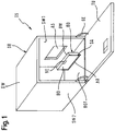
- FIG. 1 schematically shows a perspective view of an embodiment of a dishwasher GS, which has a cuboid inner container or washing container GB.
- This is composed of four wall parts, in detail the two vertically extending side walls SW1, SW2 and the largely horizontally arranged ceiling part DW and the substantially horizontally oriented bottom part BOT together.
- the inner container GB has on the front side a rectangular opening which can be closed by a door TU.
- the door TU is hinged via a hinge device GE in the region of the bottom part BOT on the two side walls SW1, SW2 pivotally.
- a rectangular incision or a recess AS is provided in the right side wall SW1, into which the trough part BW of a receptacle or a receptacle BO is inserted, in particular is fitted.
- the receptacle BO only in the pre-assembly state, ie shown before its installation in the cutout AS, as a single component in the closed state.
- a plastic material is used for him.
- the trough part BW of the receptacle BO is largely integrated liquid and vapor-tight in the cutout AS and forms a partial surface of the outer wall SW1.
- the receptacle BO preferably has a flat cuboid geometry shape.
- the outer contour of its trough portion BW is substantially rectangular and chosen such that it is adapted to the inner contour of the receiving cutout AS in the side wall SW1.
- the thickness of the receptacle BO is selected such that the front, the interior of the inner container GB facing flap part BD of the receptacle BO is largely flush with the rest of the wall surface of the side wall SW1, when the receptacle BO in the opening or the recess AS finished installed is.
- the receptacle BO as an additional component on the side wall SW1 inside set up and omit the recess AS. Then, the receptacle BO protrudes inward from the flat inner side of the side wall SW1.
- an outwardly molded trough may also be provided, which partially or completely accommodates the receptacle.
- This trough expediently has a cuboid, outwardly curved inner geometry shape, which largely corresponds to the outer geometry shape of the parallelepiped receptacle BO.
- the receptacle BO is composed of two sub-components: the edgewise, ie vertically oriented trough part BW and the hinged or pivotally mounted flap section BD.
- the flap part BD is rotatably suspended in the bottom region of the trough part BW on a pivot axis SA.
- the pivot axis SA is preferably formed here in the exemplary embodiment by two bolts or pin elements, which are mounted in the region of the receiving chamber bottom of the receptacle BO at its vertical outer edge portions, in particular formed and horizontally facing each other protrude into the interior of the receptacle BO. They are preferably in alignment with each other.
- These two pin elements each engage in an associated, correspondingly shaped groove or in a blind hole in the inner edges of the flap lid substantially vertically extending in the closed state of the receptacle so that it is rotatably mounted with respect to the imaginary alignment line of the two bearing pins.
- FIG. 2 shows the receptacle BO in a schematic representation as a detail in the closed state.
- the outlet slot AR extends substantially over the entire clear width of the trough part BW. It runs essentially in the depth direction of the washing container IB and is substantially rectilinear.
- a sprayed water jet of at least one spray arm or other spray device in the inner container GB of the dishwasher GS can penetrate through the longitudinal slot AR into the interior of the receptacle BO and in particular can eject and clean the outlet slot AR.
- a cleaner cartridge KD is housed, which has a plurality of storage chambers with liquid cleaning agents or cleaner components.
- an actuator device which can be provided on the cleaner cartridge itself, inside the receptacle BO, and / or on the outside rear wall of the receptacle, defined metered amounts of liquid flushing active ingredients from the storage chambers can be selectively, ie separately or independently remove.
- outlet slot AR in the bottom region of the trough part, it is now ensured that the respectively dispensed liquid rinse active ingredient drips out or flows out of the receptacle BO can and mix with the rinsing liquor in the bottom of the bottom tray of the inner container GB or can mix.
- a jet of water which is passed through at least one spraying device such. B. is ejected a rotating spray arm, which wash out respectively issued by the cleaner cartridge detergent from the interior of the receptacle and can largely eliminate completely.
- residues of liquid rinse active ingredient remain in the interior of the receiving container BO and / or in the outlet slot and can stick there, for example, by curing.
- the outlet slot or the outlet groove AR allows the outlet slot or the outlet groove AR, that the respective dispensed Spülwirkstoffkomponente can emerge largely free of residue from the receptacle BO and can be introduced substantially completely in terms of their dispensed dosage in the rinse.
- a finely metered metering of the respective liquid flushing component or cleaner component into the interior GB is made possible.
- this ensures that after completion of the respective rinsing the respective detergent cartridge is washed clean in the receptacle. It can be removed by an operator after completion of the wash program in the event of replacement thus largely dirt-free of washing active ingredients.
- the outlet slot also largely ensures that the detergent cartridge can also be dried during the drying step of the respective washing program.
- the flap part BD has in the middle region of its upper edge on a snap element VE as a closure which elastically braced on the inside with the outer edge of the trough part BW, in particular hooked.
- a snap element VE By moving back the spring-elastic snap element VE in an open position, the flap part can be pivoted or opened into the interior of the inner container GB.
- the pivot axis SA of the flap part BD is arranged in such a manner in the lower region of the trough part BW that in the opening end position of the flap part between its trailing edge and the front edge of the lower outer edge portion of the trough part BW a support zone for limiting the Aufklappiolo the flap part BD is formed.
- the flap part BD then acts as a support table for the cleaner cartridge, which facilitates its removal and the supply of a new, fully-filled cleaner cartridge.
- the flap part BD so in the bottom area pivotally mount the trough part BW in such a way that, in its opening end position, it is aligned substantially horizontally, ie it protrudes essentially perpendicularly in relation to the side wall SW1 into the interior of the inner container GB.
- the flap part BD has along its lower edge and along its two vertically extending side edges on an inwardly, substantially perpendicular to the inner surface of the flap part BD projecting inner edge DR.
- this inner edge DR of the flap part BD engages in the space bounded by the outer edge AR of the tub part BW.
- the flap part has an inner edge on its upper edge and its two longitudinal side edges, which engages in the closing end position of the flap part in a corresponding circumferential groove in the trough part. This groove is in the FIGS. 1 be omitted with the 3 sake of clarity.
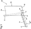
- the lower outer edge or the bottom BS of the upright attached trough part BW preferably extends obliquely downward in the direction of the bottom BOT of the inner container GB. This is in the side view of the receptacle of FIG. 3 illustrated schematically.
- the lower outer edge BS of the trough part BW is inclined with respect to the rear wall RW by more than 90 ° downwards.
- the pivot axis SA for the flap part BD is preferably arranged in the area near the bottom of the trough part BW. It has perpendicular to the inclined bottom BS of the trough part BW a predetermined height distance HA such that a gap clearance between the pivot axis or rotation axis SA and the inside of the bottom BS is provided for discharging the respective dispensed liquid cleaning component.
- the pivot axis SA of the flap part BD is in this case in the region of the lower outer edge portion of the trough part BW mounted such that the flap part BD is largely aligned in its opening end position with the lower outer edge portion BS.
- This opening end position is in the FIG. 3 dash-dotted lines and marked with the reference symbol BD *.
- a support zone or Verschränkungszone formed by the Aufklappiolo the flap part is limited. This is caused by the fact that the pivot axis SA is set back upwards by a predeterminable transverse distance with respect to the lower edge UK of the flap part BD, and therefore in the opening end position to a proportional overlap or entanglement of an outside edge zone in the region of the lower edge UK of the flap part and a inside edge zone of the lower outer edge portion of the trough part BW comes.
- the flap part can now serve as a support table for the cleaner cartridge, which is locked in relation to the contact pressure from above.
- the flap part BD preferably has one or more holding devices FK, in particular guide slots, with which the respective detergent cartridge KD can be positioned on it with a desired position.
- the cartridge KD and the fixture FK only dash-dotted lines and indicated schematically.
- the cleaner cartridge can bring in a particularly simple manner after closing the flap part in a desired, predetermined activation position in which the metering mechanism of the individual, separate pantries of the cleaner cartridge is unlocked.
- the cleaner cartridge In this activation position, the cleaner cartridge is in particular upright, i. their side walls extend substantially in the vertical direction.
- the outlet openings of the storage chambers are in the region of the lower outer edge of the trough part.
- the storage chambers of the cleaner cartridge are then aligned in particular such that adjusts in each case a substantially vertical outflow preferential direction for the liquid cleaner components.
Landscapes
- Washing And Drying Of Tableware (AREA)
Claims (21)
- Réceptacle (BO) pour un lave-vaisselle (GS) avec une partie de carter (BW) et une partie rabattable pivotante (BD) pour l'accueil d'une cartouche de nettoyant (KD), qui présente une pluralité de chambres de stockage pour des agents de lavage fluides, caractérisé par une fente d'écoulement (AR) dans le fond de la partie de carter (BW) pour permettre l'écoulement des agents de lavage fluides après leur dosage au départ des chambres de stockage de la cartouche de nettoyant (KD), dans lequel la fente d'écoulement (AR) est prévue entre un bord inférieur (UK) de la partie rabattable (BD) et une section de bord extérieur inférieure (BS) de la partie de carter (BW).
- Réceptacle selon la revendication 1, caractérisé en ce que la partie rabattable (BD) est apposée de telle sorte de façon pivotante sur la partie de carter (BW) que la fente d'écoulement (AR) est largement libérée à l'état fermé de la partie rabattable (BD).
- Réceptacle selon l'une des revendications précédentes, caractérisé en ce que la fente d'écoulement (AR) s'étend essentiellement sur la largeur intérieure libre de la partie de carter (BW).
- Réceptacle selon l'une des revendications précédentes, caractérisé en ce que la hauteur de fente de la fente d'écoulement (AR) est sélectionnée de sorte que le jet de pulvérisation d'au moins un bras de pulvérisation et/ou d'un autre dispositif de pulvérisation dans le contenant intérieur (GB) du lave-vaisselle (GS) pénètre à l'intérieur du réceptacle (BO).
- Réceptacle selon la revendication 4, caractérisé en ce que la fente d'écoulement (AR) présente une hauteur de fente entre 0,5 et 10 mm, en particulier entre 1 et 5 mm.
- Réceptacle selon l'une des revendications précédentes, caractérisé en ce qu'une coulisse de guidage (FK) pour le guidage latéral, le maintien et l'activation de la cartouche de nettoyant (KD) respectivement installée est prévue dans les deux joues latérales de la partie rabattable (BD).
- Réceptacle selon l'une des revendications précédentes, caractérisé en ce que l'axe de pivotement (SA) de la partie rabattable (BD) est prévu de telle façon dans la zone de la section de bord extérieur inférieure (BS) de la partie de carter (BW) que la partie rabattable (BD*) est, en sa position d'ouverture finale, largement alignée avec la section de bord extérieur inférieure (BS) de la partie de carter (BW).
- Réceptacle selon l'une des revendications précédentes, caractérisé en ce que l'axe de pivotement (SA) de la partie rabattable (BD) est disposé de telle façon dans la zone inférieure proche du fond de la partie de carter (BW) qu'en position d'ouverture finale de la partie rabattable (BD*), une zone d'appui pour la limitation du mouvement d'ouverture de la partie rabattable est constituée entre une zone de bord extérieur le long de son bord inférieur (UK) et le bord avant (VK) de la section de bord extérieur inférieure (BS) de la partie de carter (BW).
- Réceptacle selon l'une des revendications précédentes, caractérisé en ce que la partie rabattable (BD) est apposée de façon pivotante au moyen de deux éléments formant goujon sur le côté intérieur des joues latérales du bord extérieur (BS) de la partie de carter (BW).
- Réceptacle selon l'une des revendications précédentes, caractérisé en ce qu'un élément d'encliquetage (VE) est prévu dans la zone du bord supérieur de la partie rabattable (BD), lequel élément sert à l'encliquetage de la partie rabattable (BD), dans sa position de fermeture finale, avec la section de bord extérieur supérieure de la partie de carter (BW).
- Réceptacle selon l'une des revendications précédentes, caractérisé en ce que la partie de carter (BW) est essentiellement exécutée sous la forme d'un coffre parallélépipédique plan, qui présente un bord extérieur (AR) s'étendant sur tout le pourtour et éloigné en direction de la partie rabattable (BD).
- Réceptacle selon l'une des revendications précédentes, caractérisé en ce que la partie rabattable (BD) est exécutée sous la forme d'un coffre parallélépipédique plan, qui présente hormis sur son bord inférieur un bord intérieur éloigné par rapport à sa surface de dépose, en direction de la partie de carter (BW).
- Réceptacle selon l'une des revendications précédentes, caractérisé en ce que la partie rabattable (BD) présente sur son bord supérieur et ses deux bords latéraux longitudinaux un bord intérieur (DR) qui, en position de fermeture finale de la partie rabattable (BD), s'intègre dans une rainure périphérique dans la partie de carter (BW) correspondant au bord intérieur.
- Réceptacle selon l'une des revendications 12 ou 13, caractérisé en ce que le bord intérieur (DR) de la partie rabattable (BD) est, dans sa position de fermeture finale, logé de façon largement immergée à l'intérieur de la partie de carter (BW) et est entouré à l'extérieur par son bord extérieur (AR).
- Réceptacle selon l'une des revendications précédentes, caractérisé en ce que la partie rabattable (BD) présente, dans sa moitié supérieure, une nervure longitudinale (RI) faisant office d'aide à la préhension, s'étendant dans le sens longitudinal de la partie de carter (BW) et éloigné dans l'espace intérieur du contenant intérieur (GB) du lave-vaisselle (GS).
- Réceptacle selon l'une des revendications précédentes, caractérisé en ce que la partie rabattable (BD*) est, dans sa position d'ouverture finale, logée de façon pivotante sur la partie de carter (BW) de telle sorte qu'elle met à disposition une table de support pour une cartouche de nettoyant (KD) à insérer.
- Réceptacle selon l'une des revendications précédentes, caractérisé en ce que la section de bord extérieur inférieure (AR) de la partie de carter (BW) s'étend, dans sa position de montage dans le lave-vaisselle (GS), par rapport à la paroi arrière (RW) de la partie de carter (BW) s'étendant à la verticale, en biais vers le bas en direction du sous-plancher (BOT) du contenant intérieur (GB) du lave-vaisselle (GS).
- Réceptacle selon l'une des revendications précédentes, caractérisé en ce que la partie de carter (BW) est essentiellement orientée à la verticale dans son état de montage dans une paroi latérale (SW1) du lave-vaisselle (GS).
- Lave-vaisselle (GS) avec au moins un réceptacle (BO) selon l'une des revendications précédentes.
- Lave-vaisselle selon la revendication 19, caractérisé en ce que le réceptacle (BO) est disposé dans une niche (AS) ou sur la surface intérieure d'une paroi latérale ou de la paroi arrière de la cuve de lavage (GB).
- Lave-vaisselle selon la revendication 19 ou la revendication 20, caractérisé en ce que le réceptacle (BO) est essentiellement disposé debout à la verticale, de sorte que sa partie rabattable (BD) soit logée de façon pivotante par rapport à un axe de pivotement (SA) s'étendant essentiellement dans un plan horizontal.
Priority Applications (1)
| Application Number | Priority Date | Filing Date | Title |
|---|---|---|---|
| PL09769182T PL2306884T3 (pl) | 2008-06-23 | 2009-06-18 | Pojemnik przyjmujący na wkład czyszczący oraz zmywarka do naczyń |
Applications Claiming Priority (3)
| Application Number | Priority Date | Filing Date | Title |
|---|---|---|---|
| DE102008029427 | 2008-06-23 | ||
| DE102008042758A DE102008042758A1 (de) | 2008-06-23 | 2008-10-10 | Aufnahmebehälter für eine Reiniger-Kartusche sowie Geschirrspülmaschine |
| PCT/EP2009/057615 WO2009156333A1 (fr) | 2008-06-23 | 2009-06-18 | Récipient récepteur récipient récepteur pour cartouche de nettoyant et lave-vaisselle < |
Publications (2)
| Publication Number | Publication Date |
|---|---|
| EP2306884A1 EP2306884A1 (fr) | 2011-04-13 |
| EP2306884B1 true EP2306884B1 (fr) | 2019-02-13 |
Family
ID=41335041
Family Applications (1)
| Application Number | Title | Priority Date | Filing Date |
|---|---|---|---|
| EP09769182.8A Active EP2306884B1 (fr) | 2008-06-23 | 2009-06-18 | Récipient récepteur pour cartouche de nettoyant et lave-vaisselle |
Country Status (7)
| Country | Link |
|---|---|
| US (1) | US20110073141A1 (fr) |
| EP (1) | EP2306884B1 (fr) |
| CN (1) | CN102065742B (fr) |
| DE (1) | DE102008042758A1 (fr) |
| PL (1) | PL2306884T3 (fr) |
| RU (1) | RU2516488C2 (fr) |
| WO (1) | WO2009156333A1 (fr) |
Families Citing this family (9)
| Publication number | Priority date | Publication date | Assignee | Title |
|---|---|---|---|---|
| DE102011014893A1 (de) | 2011-03-23 | 2012-09-27 | i-clean Technologies GmbH | Vorrichtung zur Mehrfachdosierung von Reinigern |
| US9173542B2 (en) | 2012-09-05 | 2015-11-03 | Whirlpool Corporation | Dishwasher with offset open face |
| CN103799937B (zh) * | 2012-11-01 | 2017-07-28 | 松下电器产业株式会社 | 餐具清洗机 |
| EP3468440B1 (fr) * | 2016-06-13 | 2020-04-01 | BSH Hausgeräte GmbH | Dispositif de dosage pour des corps moulés de détergent dans des lave-vaisselle ménagers |
| CN107616772B (zh) * | 2016-07-14 | 2021-04-09 | 青岛海尔洗碗机有限公司 | 一种洗碗机冲洗及洗碗粉添加装置 |
| CN109730615A (zh) * | 2019-03-25 | 2019-05-10 | 珠海格力电器股份有限公司 | 可抽拉的投放装置及清洗设备 |
| CN115518934B (zh) * | 2022-10-10 | 2024-04-30 | 曲靖阳光新能源股份有限公司 | 一种可减少故障的清洗机用回篮线翻转台 |
| US12520988B2 (en) | 2023-10-20 | 2026-01-13 | Whirlpool Corporation | Household appliance and dispenser assembly |
| US12605034B2 (en) | 2023-11-30 | 2026-04-21 | Whirlpool Corporation | Dishwasher |
Family Cites Families (11)
| Publication number | Priority date | Publication date | Assignee | Title |
|---|---|---|---|---|
| US4887790A (en) * | 1987-07-07 | 1989-12-19 | Professional Compounding Centers Of America, Inc. | Troche mold and dispenser |
| US5176297A (en) * | 1990-06-14 | 1993-01-05 | Diversey Corporation | Dishwasher detergent dispenser |
| NZ335414A (en) * | 1997-01-30 | 2000-10-27 | Fisher & Paykel | Dishwasher chamber having drain pump impeller with upper disc sealing against casing, and lower blade roots radially spaced from hub to allow air accumulation for priming |
| US6138693A (en) * | 1998-11-23 | 2000-10-31 | Matz; Warren W. | Automatic detergent dispenser |
| US6315154B1 (en) * | 2000-03-15 | 2001-11-13 | Delta Consolidated Industries | Double-wall blow-molded article with pinned hinge |
| IT1320650B1 (it) * | 2000-03-29 | 2003-12-10 | Eltek Spa | Dispositivo dispensatore di agenti di lavaggio per una macchina dilavaggio domestica, in particolare una lavastoviglie. |
| AU2001292533A1 (en) * | 2000-09-04 | 2002-03-22 | Arcelik, A.S. | A washing machine with a removable detergent cartridge |
| US20040238553A1 (en) * | 2003-05-30 | 2004-12-02 | Lane Gordon S. | Container with hinged cover |
| ITTO20030117U1 (it) * | 2003-07-21 | 2005-01-22 | Elbi Int Spa | Dispositivo erogatore di detersivo in polvere per una macchina lavasto viglie. |
| US7275552B2 (en) * | 2003-12-13 | 2007-10-02 | Whirlpool Corporation | Dishwasher with bulk wash aid dispenser |
| DE102006043976A1 (de) * | 2006-09-19 | 2008-03-27 | BSH Bosch und Siemens Hausgeräte GmbH | Kartusche und wasserführendes Haushaltsgerät mit einem Reinigungsmitteldosiersystem für eine Kartusche |
-
2008
- 2008-10-10 DE DE102008042758A patent/DE102008042758A1/de not_active Withdrawn
-
2009
- 2009-06-18 RU RU2011100478/12A patent/RU2516488C2/ru active
- 2009-06-18 PL PL09769182T patent/PL2306884T3/pl unknown
- 2009-06-18 CN CN200980123910.6A patent/CN102065742B/zh not_active Expired - Fee Related
- 2009-06-18 US US12/992,897 patent/US20110073141A1/en not_active Abandoned
- 2009-06-18 EP EP09769182.8A patent/EP2306884B1/fr active Active
- 2009-06-18 WO PCT/EP2009/057615 patent/WO2009156333A1/fr not_active Ceased
Non-Patent Citations (1)
| Title |
|---|
| None * |
Also Published As
| Publication number | Publication date |
|---|---|
| CN102065742B (zh) | 2015-07-22 |
| US20110073141A1 (en) | 2011-03-31 |
| EP2306884A1 (fr) | 2011-04-13 |
| WO2009156333A1 (fr) | 2009-12-30 |
| CN102065742A (zh) | 2011-05-18 |
| RU2516488C2 (ru) | 2014-05-20 |
| RU2011100478A (ru) | 2012-07-27 |
| DE102008042758A1 (de) | 2009-12-24 |
| PL2306884T3 (pl) | 2019-08-30 |
Similar Documents
| Publication | Publication Date | Title |
|---|---|---|
| EP2306884B1 (fr) | Récipient récepteur pour cartouche de nettoyant et lave-vaisselle | |
| DE19540608C2 (de) | Vorrichtung zur Reinigerzugabe für Geschirrspülmaschinen | |
| EP2982288A1 (fr) | Lave-vaisselle, notamment lave-vaisselle menager | |
| WO2006069827A1 (fr) | Lave-vaisselle comprenant des ecrans deflecteurs | |
| DE3804302C2 (fr) | ||
| EP3305970B1 (fr) | Appareil de dosage | |
| DE102020128650A1 (de) | Haushalts-Geschirrspülmaschine und Dosiersystem hierfür | |
| EP3173006B1 (fr) | Appareil de dosage | |
| EP2805663A1 (fr) | Lave-vaisselle, notamment lave-vaisselle ménager | |
| EP2893863B1 (fr) | Lave-vaisselle | |
| EP3106074B1 (fr) | Appareil de dosage | |
| EP3721782B1 (fr) | Dispositif de dosage | |
| EP1833349B1 (fr) | Appareil menager acheminant de l'eau | |
| EP3305160A1 (fr) | Réservoir à installer dans un dispositif de dosage d'un apppareil de nettoyage | |
| BE1032620B1 (de) | Geschirrspülmaschine, insbesondere Haushaltsgeschirrspülmaschine | |
| EP3289951B1 (fr) | Lave-vaisselle, notamment lave-vaisselle ménager | |
| EP3666157B1 (fr) | Appareil de dosage | |
| DE102014115510A1 (de) | Geschirrspülautomat, insbesondere Haushaltsgeschirrspülmaschine | |
| EP3173008B1 (fr) | Récipient réservoir pour appareil de dosage | |
| EP4656120A1 (fr) | Lave-vaisselle, en particulier lave-vaisselle ménager | |
| DE102024113874A1 (de) | Geschirrspülmaschine, insbesondere Haushaltsgeschirrspülmaschine | |
| EP3173514B1 (fr) | Appareil de dosage | |
| DE4022269A1 (de) | Geschirrspuelmaschine mit besteckkorb | |
| DE102019130068A1 (de) | Dosiergerät | |
| DE102004057242A1 (de) | Schließvorrichtung für einen Salzbehälter in einer Geschirrspülmaschine |
Legal Events
| Date | Code | Title | Description |
|---|---|---|---|
| PUAI | Public reference made under article 153(3) epc to a published international application that has entered the european phase |
Free format text: ORIGINAL CODE: 0009012 |
|
| 17P | Request for examination filed |
Effective date: 20110124 |
|
| AK | Designated contracting states |
Kind code of ref document: A1 Designated state(s): AT BE BG CH CY CZ DE DK EE ES FI FR GB GR HR HU IE IS IT LI LT LU LV MC MK MT NL NO PL PT RO SE SI SK TR |
|
| AX | Request for extension of the european patent |
Extension state: AL BA RS |
|
| DAX | Request for extension of the european patent (deleted) | ||
| RAP1 | Party data changed (applicant data changed or rights of an application transferred) |
Owner name: BSH HAUSGERAETE GMBH |
|
| GRAP | Despatch of communication of intention to grant a patent |
Free format text: ORIGINAL CODE: EPIDOSNIGR1 |
|
| STAA | Information on the status of an ep patent application or granted ep patent |
Free format text: STATUS: GRANT OF PATENT IS INTENDED |
|
| INTG | Intention to grant announced |
Effective date: 20180918 |
|
| GRAS | Grant fee paid |
Free format text: ORIGINAL CODE: EPIDOSNIGR3 |
|
| GRAA | (expected) grant |
Free format text: ORIGINAL CODE: 0009210 |
|
| STAA | Information on the status of an ep patent application or granted ep patent |
Free format text: STATUS: THE PATENT HAS BEEN GRANTED |
|
| AK | Designated contracting states |
Kind code of ref document: B1 Designated state(s): AT BE BG CH CY CZ DE DK EE ES FI FR GB GR HR HU IE IS IT LI LT LU LV MC MK MT NL NO PL PT RO SE SI SK TR |
|
| REG | Reference to a national code |
Ref country code: GB Ref legal event code: FG4D Free format text: NOT ENGLISH |
|
| REG | Reference to a national code |
Ref country code: CH Ref legal event code: EP Ref country code: AT Ref legal event code: REF Ref document number: 1095737 Country of ref document: AT Kind code of ref document: T Effective date: 20190215 |
|
| REG | Reference to a national code |
Ref country code: IE Ref legal event code: FG4D Free format text: LANGUAGE OF EP DOCUMENT: GERMAN |
|
| REG | Reference to a national code |
Ref country code: DE Ref legal event code: R096 Ref document number: 502009015617 Country of ref document: DE |
|
| REG | Reference to a national code |
Ref country code: LT Ref legal event code: MG4D |
|
| REG | Reference to a national code |
Ref country code: NL Ref legal event code: MP Effective date: 20190213 |
|
| PG25 | Lapsed in a contracting state [announced via postgrant information from national office to epo] |
Ref country code: PT Free format text: LAPSE BECAUSE OF FAILURE TO SUBMIT A TRANSLATION OF THE DESCRIPTION OR TO PAY THE FEE WITHIN THE PRESCRIBED TIME-LIMIT Effective date: 20190613 Ref country code: SE Free format text: LAPSE BECAUSE OF FAILURE TO SUBMIT A TRANSLATION OF THE DESCRIPTION OR TO PAY THE FEE WITHIN THE PRESCRIBED TIME-LIMIT Effective date: 20190213 Ref country code: NO Free format text: LAPSE BECAUSE OF FAILURE TO SUBMIT A TRANSLATION OF THE DESCRIPTION OR TO PAY THE FEE WITHIN THE PRESCRIBED TIME-LIMIT Effective date: 20190513 Ref country code: FI Free format text: LAPSE BECAUSE OF FAILURE TO SUBMIT A TRANSLATION OF THE DESCRIPTION OR TO PAY THE FEE WITHIN THE PRESCRIBED TIME-LIMIT Effective date: 20190213 Ref country code: LT Free format text: LAPSE BECAUSE OF FAILURE TO SUBMIT A TRANSLATION OF THE DESCRIPTION OR TO PAY THE FEE WITHIN THE PRESCRIBED TIME-LIMIT Effective date: 20190213 Ref country code: NL Free format text: LAPSE BECAUSE OF FAILURE TO SUBMIT A TRANSLATION OF THE DESCRIPTION OR TO PAY THE FEE WITHIN THE PRESCRIBED TIME-LIMIT Effective date: 20190213 |
|
| PG25 | Lapsed in a contracting state [announced via postgrant information from national office to epo] |
Ref country code: BG Free format text: LAPSE BECAUSE OF FAILURE TO SUBMIT A TRANSLATION OF THE DESCRIPTION OR TO PAY THE FEE WITHIN THE PRESCRIBED TIME-LIMIT Effective date: 20190513 Ref country code: GR Free format text: LAPSE BECAUSE OF FAILURE TO SUBMIT A TRANSLATION OF THE DESCRIPTION OR TO PAY THE FEE WITHIN THE PRESCRIBED TIME-LIMIT Effective date: 20190514 Ref country code: LV Free format text: LAPSE BECAUSE OF FAILURE TO SUBMIT A TRANSLATION OF THE DESCRIPTION OR TO PAY THE FEE WITHIN THE PRESCRIBED TIME-LIMIT Effective date: 20190213 Ref country code: HR Free format text: LAPSE BECAUSE OF FAILURE TO SUBMIT A TRANSLATION OF THE DESCRIPTION OR TO PAY THE FEE WITHIN THE PRESCRIBED TIME-LIMIT Effective date: 20190213 Ref country code: IS Free format text: LAPSE BECAUSE OF FAILURE TO SUBMIT A TRANSLATION OF THE DESCRIPTION OR TO PAY THE FEE WITHIN THE PRESCRIBED TIME-LIMIT Effective date: 20190613 |
|
| PG25 | Lapsed in a contracting state [announced via postgrant information from national office to epo] |
Ref country code: IT Free format text: LAPSE BECAUSE OF FAILURE TO SUBMIT A TRANSLATION OF THE DESCRIPTION OR TO PAY THE FEE WITHIN THE PRESCRIBED TIME-LIMIT Effective date: 20190213 Ref country code: RO Free format text: LAPSE BECAUSE OF FAILURE TO SUBMIT A TRANSLATION OF THE DESCRIPTION OR TO PAY THE FEE WITHIN THE PRESCRIBED TIME-LIMIT Effective date: 20190213 Ref country code: SK Free format text: LAPSE BECAUSE OF FAILURE TO SUBMIT A TRANSLATION OF THE DESCRIPTION OR TO PAY THE FEE WITHIN THE PRESCRIBED TIME-LIMIT Effective date: 20190213 Ref country code: CZ Free format text: LAPSE BECAUSE OF FAILURE TO SUBMIT A TRANSLATION OF THE DESCRIPTION OR TO PAY THE FEE WITHIN THE PRESCRIBED TIME-LIMIT Effective date: 20190213 Ref country code: EE Free format text: LAPSE BECAUSE OF FAILURE TO SUBMIT A TRANSLATION OF THE DESCRIPTION OR TO PAY THE FEE WITHIN THE PRESCRIBED TIME-LIMIT Effective date: 20190213 Ref country code: DK Free format text: LAPSE BECAUSE OF FAILURE TO SUBMIT A TRANSLATION OF THE DESCRIPTION OR TO PAY THE FEE WITHIN THE PRESCRIBED TIME-LIMIT Effective date: 20190213 Ref country code: ES Free format text: LAPSE BECAUSE OF FAILURE TO SUBMIT A TRANSLATION OF THE DESCRIPTION OR TO PAY THE FEE WITHIN THE PRESCRIBED TIME-LIMIT Effective date: 20190213 |
|
| REG | Reference to a national code |
Ref country code: DE Ref legal event code: R097 Ref document number: 502009015617 Country of ref document: DE |
|
| PLBE | No opposition filed within time limit |
Free format text: ORIGINAL CODE: 0009261 |
|
| STAA | Information on the status of an ep patent application or granted ep patent |
Free format text: STATUS: NO OPPOSITION FILED WITHIN TIME LIMIT |
|
| 26N | No opposition filed |
Effective date: 20191114 |
|
| PG25 | Lapsed in a contracting state [announced via postgrant information from national office to epo] |
Ref country code: MC Free format text: LAPSE BECAUSE OF FAILURE TO SUBMIT A TRANSLATION OF THE DESCRIPTION OR TO PAY THE FEE WITHIN THE PRESCRIBED TIME-LIMIT Effective date: 20190213 |
|
| REG | Reference to a national code |
Ref country code: CH Ref legal event code: PL |
|
| GBPC | Gb: european patent ceased through non-payment of renewal fee |
Effective date: 20190618 |
|
| PG25 | Lapsed in a contracting state [announced via postgrant information from national office to epo] |
Ref country code: SI Free format text: LAPSE BECAUSE OF FAILURE TO SUBMIT A TRANSLATION OF THE DESCRIPTION OR TO PAY THE FEE WITHIN THE PRESCRIBED TIME-LIMIT Effective date: 20190213 |
|
| REG | Reference to a national code |
Ref country code: BE Ref legal event code: MM Effective date: 20190630 |
|
| PG25 | Lapsed in a contracting state [announced via postgrant information from national office to epo] |
Ref country code: IE Free format text: LAPSE BECAUSE OF NON-PAYMENT OF DUE FEES Effective date: 20190618 Ref country code: GB Free format text: LAPSE BECAUSE OF NON-PAYMENT OF DUE FEES Effective date: 20190618 |
|
| PG25 | Lapsed in a contracting state [announced via postgrant information from national office to epo] |
Ref country code: LU Free format text: LAPSE BECAUSE OF NON-PAYMENT OF DUE FEES Effective date: 20190618 Ref country code: BE Free format text: LAPSE BECAUSE OF NON-PAYMENT OF DUE FEES Effective date: 20190630 Ref country code: CH Free format text: LAPSE BECAUSE OF NON-PAYMENT OF DUE FEES Effective date: 20190630 Ref country code: LI Free format text: LAPSE BECAUSE OF NON-PAYMENT OF DUE FEES Effective date: 20190630 |
|
| PG25 | Lapsed in a contracting state [announced via postgrant information from national office to epo] |
Ref country code: FR Free format text: LAPSE BECAUSE OF NON-PAYMENT OF DUE FEES Effective date: 20190630 |
|
| REG | Reference to a national code |
Ref country code: AT Ref legal event code: MM01 Ref document number: 1095737 Country of ref document: AT Kind code of ref document: T Effective date: 20190618 |
|
| PG25 | Lapsed in a contracting state [announced via postgrant information from national office to epo] |
Ref country code: AT Free format text: LAPSE BECAUSE OF NON-PAYMENT OF DUE FEES Effective date: 20190618 |
|
| PG25 | Lapsed in a contracting state [announced via postgrant information from national office to epo] |
Ref country code: CY Free format text: LAPSE BECAUSE OF FAILURE TO SUBMIT A TRANSLATION OF THE DESCRIPTION OR TO PAY THE FEE WITHIN THE PRESCRIBED TIME-LIMIT Effective date: 20190213 |
|
| PG25 | Lapsed in a contracting state [announced via postgrant information from national office to epo] |
Ref country code: HU Free format text: LAPSE BECAUSE OF FAILURE TO SUBMIT A TRANSLATION OF THE DESCRIPTION OR TO PAY THE FEE WITHIN THE PRESCRIBED TIME-LIMIT; INVALID AB INITIO Effective date: 20090618 Ref country code: MT Free format text: LAPSE BECAUSE OF FAILURE TO SUBMIT A TRANSLATION OF THE DESCRIPTION OR TO PAY THE FEE WITHIN THE PRESCRIBED TIME-LIMIT Effective date: 20190213 |
|
| PG25 | Lapsed in a contracting state [announced via postgrant information from national office to epo] |
Ref country code: MK Free format text: LAPSE BECAUSE OF FAILURE TO SUBMIT A TRANSLATION OF THE DESCRIPTION OR TO PAY THE FEE WITHIN THE PRESCRIBED TIME-LIMIT Effective date: 20190213 |
|
| REG | Reference to a national code |
Ref country code: DE Ref legal event code: R084 Ref document number: 502009015617 Country of ref document: DE |
|
| PGFP | Annual fee paid to national office [announced via postgrant information from national office to epo] |
Ref country code: DE Payment date: 20250630 Year of fee payment: 17 Ref country code: PL Payment date: 20250610 Year of fee payment: 17 |
|
| PGFP | Annual fee paid to national office [announced via postgrant information from national office to epo] |
Ref country code: TR Payment date: 20250613 Year of fee payment: 17 |