EP2307175B1 - Machine-outil à main - Google Patents
Machine-outil à main Download PDFInfo
- Publication number
- EP2307175B1 EP2307175B1 EP09779572A EP09779572A EP2307175B1 EP 2307175 B1 EP2307175 B1 EP 2307175B1 EP 09779572 A EP09779572 A EP 09779572A EP 09779572 A EP09779572 A EP 09779572A EP 2307175 B1 EP2307175 B1 EP 2307175B1
- Authority
- EP
- European Patent Office
- Prior art keywords
- power tool
- portable power
- workpiece
- tool
- unit
- Prior art date
- Legal status (The legal status is an assumption and is not a legal conclusion. Google has not performed a legal analysis and makes no representation as to the accuracy of the status listed.)
- Not-in-force
Links
- 238000003754 machining Methods 0.000 claims description 37
- 238000006073 displacement reaction Methods 0.000 claims description 22
- 230000003287 optical effect Effects 0.000 claims description 13
- 238000001514 detection method Methods 0.000 claims description 8
- 230000001105 regulatory effect Effects 0.000 claims 1
- 238000012545 processing Methods 0.000 description 33
- 238000003801 milling Methods 0.000 description 20
- 238000005553 drilling Methods 0.000 description 11
- 239000000853 adhesive Substances 0.000 description 8
- 230000001070 adhesive effect Effects 0.000 description 8
- 239000003550 marker Substances 0.000 description 6
- 238000012937 correction Methods 0.000 description 5
- 230000005540 biological transmission Effects 0.000 description 3
- 230000005672 electromagnetic field Effects 0.000 description 3
- 238000000034 method Methods 0.000 description 3
- 238000003825 pressing Methods 0.000 description 3
- 230000006378 damage Effects 0.000 description 2
- 238000011156 evaluation Methods 0.000 description 2
- 238000005286 illumination Methods 0.000 description 2
- 238000001454 recorded image Methods 0.000 description 2
- 244000025254 Cannabis sativa Species 0.000 description 1
- 235000012766 Cannabis sativa ssp. sativa var. sativa Nutrition 0.000 description 1
- 235000012765 Cannabis sativa ssp. sativa var. spontanea Nutrition 0.000 description 1
- 208000027418 Wounds and injury Diseases 0.000 description 1
- 230000004913 activation Effects 0.000 description 1
- 235000009120 camo Nutrition 0.000 description 1
- 235000005607 chanvre indien Nutrition 0.000 description 1
- 238000004140 cleaning Methods 0.000 description 1
- 239000012141 concentrate Substances 0.000 description 1
- 230000001419 dependent effect Effects 0.000 description 1
- 238000011161 development Methods 0.000 description 1
- 230000000694 effects Effects 0.000 description 1
- 238000005516 engineering process Methods 0.000 description 1
- 239000002657 fibrous material Substances 0.000 description 1
- 239000011487 hemp Substances 0.000 description 1
- 238000003384 imaging method Methods 0.000 description 1
- 208000014674 injury Diseases 0.000 description 1
- 238000012423 maintenance Methods 0.000 description 1
- 239000000463 material Substances 0.000 description 1
- 239000007779 soft material Substances 0.000 description 1
- 239000000725 suspension Substances 0.000 description 1
Images


Classifications
-
- B—PERFORMING OPERATIONS; TRANSPORTING
- B25—HAND TOOLS; PORTABLE POWER-DRIVEN TOOLS; MANIPULATORS
- B25H—WORKSHOP EQUIPMENT, e.g. FOR MARKING-OUT WORK; STORAGE MEANS FOR WORKSHOPS
- B25H1/00—Work benches; Portable stands or supports for positioning portable tools or work to be operated on thereby
- B25H1/0021—Stands, supports or guiding devices for positioning portable tools or for securing them to the work
- B25H1/0078—Guiding devices for hand tools
- B25H1/0092—Guiding devices for hand tools by optical means
-
- B—PERFORMING OPERATIONS; TRANSPORTING
- B23—MACHINE TOOLS; METAL-WORKING NOT OTHERWISE PROVIDED FOR
- B23Q—DETAILS, COMPONENTS, OR ACCESSORIES FOR MACHINE TOOLS, e.g. ARRANGEMENTS FOR COPYING OR CONTROLLING; MACHINE TOOLS IN GENERAL CHARACTERISED BY THE CONSTRUCTION OF PARTICULAR DETAILS OR COMPONENTS; COMBINATIONS OR ASSOCIATIONS OF METAL-WORKING MACHINES, NOT DIRECTED TO A PARTICULAR RESULT
- B23Q17/00—Arrangements for observing, indicating or measuring on machine tools
- B23Q17/22—Arrangements for observing, indicating or measuring on machine tools for indicating or measuring existing or desired position of tool or work
- B23Q17/2233—Arrangements for observing, indicating or measuring on machine tools for indicating or measuring existing or desired position of tool or work for adjusting the tool relative to the workpiece
-
- B—PERFORMING OPERATIONS; TRANSPORTING
- B23—MACHINE TOOLS; METAL-WORKING NOT OTHERWISE PROVIDED FOR
- B23Q—DETAILS, COMPONENTS, OR ACCESSORIES FOR MACHINE TOOLS, e.g. ARRANGEMENTS FOR COPYING OR CONTROLLING; MACHINE TOOLS IN GENERAL CHARACTERISED BY THE CONSTRUCTION OF PARTICULAR DETAILS OR COMPONENTS; COMBINATIONS OR ASSOCIATIONS OF METAL-WORKING MACHINES, NOT DIRECTED TO A PARTICULAR RESULT
- B23Q17/00—Arrangements for observing, indicating or measuring on machine tools
- B23Q17/24—Arrangements for observing, indicating or measuring on machine tools using optics or electromagnetic waves
-
- B—PERFORMING OPERATIONS; TRANSPORTING
- B25—HAND TOOLS; PORTABLE POWER-DRIVEN TOOLS; MANIPULATORS
- B25H—WORKSHOP EQUIPMENT, e.g. FOR MARKING-OUT WORK; STORAGE MEANS FOR WORKSHOPS
- B25H1/00—Work benches; Portable stands or supports for positioning portable tools or work to be operated on thereby
- B25H1/0021—Stands, supports or guiding devices for positioning portable tools or for securing them to the work
-
- B—PERFORMING OPERATIONS; TRANSPORTING
- B27—WORKING OR PRESERVING WOOD OR SIMILAR MATERIAL; NAILING OR STAPLING MACHINES IN GENERAL
- B27C—PLANING, DRILLING, MILLING, TURNING OR UNIVERSAL MACHINES FOR WOOD OR SIMILAR MATERIAL
- B27C5/00—Machines designed for producing special profiles or shaped work, e.g. by rotary cutters; Equipment therefor
- B27C5/10—Portable hand-operated wood-milling machines; Routers
-
- Y—GENERAL TAGGING OF NEW TECHNOLOGICAL DEVELOPMENTS; GENERAL TAGGING OF CROSS-SECTIONAL TECHNOLOGIES SPANNING OVER SEVERAL SECTIONS OF THE IPC; TECHNICAL SUBJECTS COVERED BY FORMER USPC CROSS-REFERENCE ART COLLECTIONS [XRACs] AND DIGESTS
- Y10—TECHNICAL SUBJECTS COVERED BY FORMER USPC
- Y10T—TECHNICAL SUBJECTS COVERED BY FORMER US CLASSIFICATION
- Y10T409/00—Gear cutting, milling, or planing
- Y10T409/30—Milling
- Y10T409/306216—Randomly manipulated, work supported, or work following device
- Y10T409/306552—Randomly manipulated
- Y10T409/306608—End mill [e.g., router, etc.]
Definitions
- the present invention relates to a hand tool according to the preamble of claim 1.
- a hand tool for example, from the US 5,010,652 out.
- Such hemp machine tools are known in the art and may, for example, be a jigsaw, a mill, a drill, a stapler or a spot welder.
- These hand tool machines have in common that they are independent of a workpiece to be machined.
- the hand tool is positioned at the desired processing point and optionally moved during or on the workpiece during processing.
- a punctiform machining for example by a drill or a stapler
- the hand tool is once aligned and not crazy during the machining of the workpiece.
- the machining takes place during a shifting operation of the tool on the workpiece, so that an operator must continuously carry out the machining with great attention.
- one or more markings are applied to the workpiece in order to position the hand tool machine for machining.
- a point at which a hole is to be drilled with the drill drawn with a pen or a scriber and / or marked with a grain.
- a line along which the machining of the workpiece is to be performed is marked on the workpiece so that the power tool can be guided along that line.
- the device has the US 5,010,652 a light source for illuminating the workpiece to be machined and a sensor unit in the form of photoresistors. Due to the different reflection of the workpiece and a marking line mounted on the workpiece, the photoresistors detect any leaving of the marking line. In this case, the angle of attack of the saw blade of the jigsaw is changed to align the machine tool again on the marking line.
- a hand tool machine in which the machining accuracy and speed is improved.
- This object is achieved by a hand tool with the features listed in claim 1.
- the object is achieved by the handheld power tool having a Sen-6DO, sorö, which is designed such that it can provide a provided on a workpiece processing mark defining a desired position of the tool, and a control unit based on the signal output of the sensor unit is determined, a deviation of the actual position is determined by the target position is provided, wherein a positioning unit is provided, which is designed such that it performs an automatic correction of the power tool from the is position to the desired position.
- a basic idea of the invention therefore consists in designing the handheld power tool in such a way that it automatically detects the machining mark and determines the deviation from the machining mark. This deviation can then be compensated automatically by the positioning unit. It may also be useful to combine the automatic positioning with a manual correction to For example, when processing with a jigsaw to compensate immediately for a deviation from the machining mark on the one hand and on the other hand to indicate the deviation. This prevents the user from causing an even greater deviation from the processing mark during further processing. This ensures that setting limits of the positioning unit, which can vary depending on the specific configuration of the power tool, can not be achieved because the user receives the additional feedback for the manual correction.
- the machining marks to be registered can mark either a machining point or a machining line, which has no effect on the correction of the position.
- the hand tool machines can be designed with a sliding shoe, with which they rest on the workpiece for guidance, whereby on the one hand a firm support on the workpiece is ensured and on the other hand, the power tool can be easily moved on the workpiece.
- the sensor unit may comprise an optical detection unit and the control unit may comprise a microcontroller.
- the optical detection unit of the handheld power tool can take pictures and calculate the deviation based on the recorded images. By image acquisition and processing, a processing mark applied to the workpiece can be detected.
- imaging systems are already widely used in other fields of technology and can be provided at low cost.
- the optical detection unit may be configured to receive an image line by line, and the control unit may be configured to determine the deviation based on the individual lines. This type of line-based evaluation can be performed in a particularly simple manner and requires only low processing power from the microcontroller.
- line-shaped markings can be detected particularly easily in this way.
- the optical detection unit may have a ring optics. Due to the usually short distance between the tool and the workpiece, this particular type of optics can contribute to improved registration of the marking.
- the sensor unit may be provided detachably on the power tool, for example by means of a plug connection. So it can be easily possible to exchange the same camera between different types of power tools, if they have a suitable connector. Since this type of positioning is in principle suitable for a variety of tools, the tools can be operated with the same camera, if necessary. In addition, the camera may be removed from the power tool in this manner for easy cleaning or maintenance, which will occasionally be required due to the frequent machining and the flying chips generated thereby.
- the positioning unit has an actuator and a corresponding controller for each independent positioning direction.
- the actuators are preferably designed as a servomotor, stepper motor or piezoelectric actuator, which are particularly well suited for accurate control.
- the signal output unit may comprise optical signal output means. Due to the usually resulting from the processing noise development can be visually displayed in a manner reliable for the user, the deviation.
- the optical signal output means preferably comprise LEDs or a display. On the display, the deviation can be represented concretely, for example in the form of a target point and a crosshair, or in the form of arrows or bars indicating the direction and magnitude of the deviation.
- LEDs may be provided in the positioning directions to indicate a deviation in each positioning direction. Another advantage of LEDs is that Low power consumption, which is particularly important in battery-powered tools.
- control unit can be designed such that the positioning unit and a processing by the power tool are jointly controllable.
- an automatic machining of the workpiece can be performed, wherein the user is required only for the positioning and optionally fixing the power tool.
- a drilling machine can be controlled after its positioning in order to independently drill a plurality of holes according to specific specifications in the workpiece, without having to reposition the drill for each hole. Even the automatic sawing of holes with a jigsaw is possible.
- the drill it is necessary to perform positioning in the axis perpendicular to the workpiece in addition to the positioning on the workpiece in order to drill the holes can. This is made possible by the implementation of a further positioning direction in the positioning unit.
- the handheld power tool may also include a sighting device with which the area which can be detected by the sensor unit can be marked on the workpiece.
- a sighting device with which the area which can be detected by the sensor unit can be marked on the workpiece.
- This can be embodied, for example, in the form of an optical sighting device or in the manner of a template which is guided on the workpiece, wherein within this marking the desired position can be detected on the workpiece.
- the target device preferably comprises at least one luminous element and the region in which the marking can be detected by the sensor unit can be marked by radiated light from the luminous element. Due to the low power consumption, the light-emitting element can be embodied in particular in the form of at least one LED.
- the mark For example, light can consist of illumination of the region of the workpiece which can be detected by the sensor unit.
- the illumination simultaneously improves the detection by the sensor unit, since insufficient lighting or possible shading is compensated by the handheld power tool itself. Marking in the form of a luminous frame on the workpiece, in particular in a slightly perceptible color, is also possible to mark the area thereon.
- the aiming device can be embodied with a marking device for marking the preferred direction of displacement of the handheld power tool.
- this can e.g. be performed by a specially shaped mark for the detection of the desired position, if this example is formed as a triangle, wherein a corner of the triangle marks the preferred direction of displacement.
- the user can concentrate fully on the operation of the power tool and he does not have to observe the marking for editing additionally. This can be helpful, in particular in the case of linear processing.
- the handheld power tool can have path detection means for detecting a displacement of the handheld power tool on the workpiece.
- path detection means for detecting a displacement of the handheld power tool on the workpiece.
- a mechanical guide element can be provided on the hand tool in the area of contact with the workpiece that can be engaged in a groove or groove of the workpiece or can be applied to an edge of the workpiece.
- a kind of fin may be provided in the direction of displacement on the back of the tool in order to prevent the to improve lateral guidance. The fin can engage in the recess formed by the sawing and prevent lateral displacement of the power tool. This allows faster machining of the workpiece and corrections to the position are required to a lesser extent.
- the mechanical guide element is preferably held with a spring device retractable on the power tool.
- machining can be started within a surface of the workpiece, with the fin being buried in the tool. Once a sufficiently large piece has been sawn, the fin may spring out of the tool and engage in the cut formed by sawing.
- the mechanical guide member may be releasably connected to the power tool, whereby the guide can be adjusted depending on specific requirements for the machining or specifications by the workpiece. For example, wider cuts through the use of wider blades or wider cutters require wider guide elements to allow precise guidance, and vice versa. This can be achieved by replacing the fin.
- adhesive elements with rubber or friction linings are provided on the handheld power tool such that they are movable between a first position in which they do not rest on the workpiece, and a second position in which they rest on the workpiece.
- adhesive elements may be provided in the shoe which are pushed out of the shoe for machining at a fixed position and are otherwise buried in the shoe. This leads to a kind of jacking up the power tool, since the contact with the workpiece is made only on the adhesive elements. The hand tool can then be fixed by pressing the adhesive elements against the workpiece at this.
- the adhesive elements can also be held pivotably on the hand tool, so that they can be pivoted from a position in which they do not rest against the workpiece to a position in which they rest on the workpiece.
- This specific embodiment is exclusively dependent on the type of tool and the type of workpiece.
- the at least one adhesive element can comprise an electromagnetic element and the hand tool machine can be pressed against the workpiece by the application of an electromagnetic field. If magnetic workpieces can be processed with the hand tool, can For example, by applying an electromagnetic field with an electromagnet on the hand tool or smaller electromagnet on the adhesive elements a fixation of the power tool on the workpiece can be achieved. Since a force is exerted here by the magnet itself, the user is relieved of the fixation.
- a suction device is provided, with which in the contact region between the power tool and the workpiece, a negative pressure is buildable.
- the suction device may be associated with an external vacuum pump for generating the negative pressure.
- the negative pressure can be built, which is easily possible, especially for smooth workpieces.
- the area of the negative pressure is surrounded by a rubber seal, so that the negative pressure can be easily maintained without the vacuum pump has to work continuously.
- the suction device may have a reverse operation by generating an overpressure.
- an overpressure can be generated in a contact region between the hand tool machine and the workpiece and the hand tool machine can be moved on a forming air cushion on the workpiece.
- the shoe undergoes less resistance when sliding on the workpiece, which further simplifies the machining of the workpiece.
- the hand tool may have rollers in the contact area to the workpiece.
- the rollers are preferably made of a rubber-like material, whereby the adhesion of the rollers is increased on the workpiece.
- the rollers are preferably made of a rubber-like material, whereby the adhesion of the rollers is increased on the workpiece.
- the adhesion to the workpiece is significantly improved.
- the use of at least one roller as a path-detecting means for the displacement of the power tool is also conceivable.
- the rollers can be driven by the control unit.
- the power tool can be moved by driving the rollers on the workpiece which provides a further degree of freedom for the machining of the workpiece.
- the displacement of the tool is coordinated with the machining by the control unit.
- the fixation of the tool on the workpiece for example via the control of the electromagnets or the activation of the vacuum generation, is coordinated with the displacement of the tool, so that the tool can perform the quasi autonomous processing.
- the direction of displacement of the tool can be influenced, so that approximately any machining of the workpiece are possible.
- an interface for the data exchange can be provided on the handheld power tool.
- required control commands can be transmitted, for example, from an external data processing device to the power tool via the interface, so that a high degree of flexibility in processing is possible.
- the transmission of groups of control commands combined into programs is also possible.
- the required program has to be transferred to the hand tool.
- it is also possible to store a plurality of programs in the handheld power tool however, the memory options are usually limited and the user interface is usually small, corresponding to the size of the handheld power tools. Therefore, although in principle a selection or even the creation of programs on the hand tool itself is possible, but this is not feasible with sufficient comfort.
- the programs are preferably created and selected via the external data processing device, so that only the processing has to be implemented with the handheld power tool.
- further information such as, for example, path lengths covered during processing, service information about the state of the tool or possibly also current operating states can be queried via the interface.
- a wireless interface increases the security of data transmission due to the nature of the frequently separating or exciting processing performed with the handheld power tools and the use in such a work environment. Furthermore, damage or severance of a cable used for data transmission can be avoided.
- a corresponding positioning method for the hand tool described above results from the following details with the advantage that the hand tool is safe, precise and time-saving manageable.
- the desired position of the hand tool is defined on a workpiece to be machined via a processing mark and detected by the power tool.
- a deviation of the actual position from the desired position is determined and then automatically corrected by the hand tool.
- corresponding signals representing the determined deviation can be output to a user until he has corrected the deviation manually.
- images can be taken by means of the handheld power tool and position deviations from the processing mark can be determined on the basis of the recorded images.
- each image can be decomposed into individual image lines and the deviation from the processing mark can be determined by analyzing the image lines.
- machining of the workpiece is independently carried out by the power tool.
- the power tool For machining the workpiece, the power tool can be moved perpendicular thereto. In this case, the deviation from the processing mark, in particular the size and direction of the deviation, is visually displayed.
- the area of the workpiece is marked, in which the determination of the desired position is feasible.
- this area can be marked with light, which in addition a preferred displacement direction can be marked on the hand tool on this.
- a displacement of the power tool on the workpiece can be detected.
- the power tool is guided with a mechanical guide element in a recess or on an edge of the workpiece, wherein the mechanical guide element is replaced depending on the workpiece and / or the processing.
- the mechanical guide element is retractable in the power tool and is pressed by spring force when reaching the depression in this.
- the power tool can be pressed against the workpiece via adhesive elements with rubber or friction linings and fixed to it.
- the power tool is fixed by the application of an electromagnetic field or by generating a negative pressure on the workpiece.
- the negative pressure of an internal or external, not belonging to the power tool pump can be generated.
- an overpressure can be generated in a contact region between the hand tool machine and the workpiece and the hand tool machine can be moved on a forming air cushion on the workpiece and / or be moved over freely rotating or defined driven rollers on the workpiece.
- the hand tool can be transmitted via a control interface control commands for the machining of the workpiece.
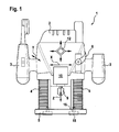
- FIG. 1 shows a designed as a milling cutter 1 according to a first embodiment of the present invention hand tool.
- the milling cutter 1 comprises a main body 2 with handles 3 provided laterally thereon, two length-adjustable legs laterally provided on the underside of the main body 2, which extend vertically downwards and are each surrounded by a Falkenbalg 4, and a circular one provided at the lower end of the legs Sliding shoe 5. Furthermore, located on the base body 2, a fixing lever 6, via which the legs are locked relative to the base body 2, and a height-adjustable stop 7, which is fixable via a locking screw 8 and a movement of the shoe 5 in the direction of the Basic body 2 limited.
- a cutter holder 9 is provided for receiving a milling cutter, not shown.
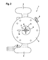
- the cutter holder 9 is as in FIG. 2 can be seen, along the arrow directions X, Y parallel to the plane of the shoe 5 slidably held on the base body 2.
- the cutter holder 9 is movable in an arrow direction Z perpendicular to the sliding block 5.
- 2 electric servomotors are provided within the base body, via which the respective position of the cutter holder 9 exactly in all three directions of the arrow X, Y, Z is independently adjustable.
- a directed to the ground camera 10 is provided as a sensor unit.
- the camera 10 is designed so that images are captured line by line.
- optics in the camera 10 a ring optics not shown in detail is used.
- the camera 10 is oriented to engage the underlying area of a workpiece through a recess 11 in the shoe 5.
- a square indicator 12 is provided as a signal output unit, the corners of which are opposite in pairs in horizontal or vertical direction, wherein in each corner an LED, not shown, is provided which is independently controllable.
- the camera 10 is associated with a target device not shown in detail, which projects a triangular target mark 13 through the recess 11 of the shoe through the workpiece.
- the triangular target marking 13 is formed with two equal inner angles and a smaller inner angle, so that the smaller inner angle simultaneously marks a preferred displacement direction on the workpiece.
- the basic body 2 automatically results in the preferred direction of displacement from the natural position of the milling cutter 1 by the user in front of him with two hands, so that he pushes away the milling cutter 1 in the indicated arrow Y from him.
- a control unit which is connected to the camera 10 on its input side.
- the control unit On the output side, the control unit with three regulators, which regulate the positioning of the cutter holder 9 in the directions X, Y, Z, and connected to the display 12.
- the control unit is connected to another controller for driving the rotation of the cutter holder. The control of the controller takes place based on the processed camera signals.
- the control unit is designed as a microcontroller and has an interface for data exchange. The interface is cordless and not visible.
- a mechanical guide element in the form of a fin 14 is provided on the underside, which is resiliently held on the sliding block 5.
- the suspension is designed so that the fin 14 is movable in a direction perpendicular to the sliding shoe 5.
- the fin 14 is elongated in the Y-direction, so that the fin 14 coincides with the preferred direction of displacement of the milling cutter 1.
- the fin 14 is held exchangeably on the sliding shoe 5 in order to be able to use a fin 14 with a width corresponding thereto, depending on the cutter used.
- rubber elements 15 are provided in the shoe, which are held on guides 16.
- the rubber elements 15 are adjustable via the guides 16 perpendicular to the shoe 5 and completely retractable therein.
- the adjustment of the rubber elements 15 is controllable via the control unit.
- the mill 1 can be used as a drill, as due to the high rotational speeds, especially in soft or fibrous material tearing of the holes is prevented compared to drilling with a drill.
- a crosshair-shaped mark 17 is first attached to the workpiece at the location of the hole to be drilled.
- the mill 1 is positioned on the workpiece and the control unit determines based on signals transmitted from the camera 10, a deviation of the current actual position of the cutter of the Mark 17 of the desired position.
- the image of the camera 10 in the control unit is evaluated line by line and the deviation is determined based on this evaluation.
- the user helps the target mark 13, with which he can bring the marker 17 in the range that can be detected by the camera 10 of the mill 1.
- the miller 1 If the marker 17 can not be detected, the miller 1 outputs it as an error in that all four LEDs of the display 12 flash simultaneously. If the mark 17 is detected but outside the setting range of the cutter holder 9, the direction of the necessary displacement of the cutter 1 by the user via the corresponding LEDs of the display 12 is signaled. The luminous intensity of the LEDs corresponds to the distance from the mark 17.
- the LEDs of the display 12 go out and the user can start processing by pressing a button on a button (not shown).
- the control unit moves the rubber elements 15 out of the sliding block 5, so that the milling cutter 1 is no longer displaceable.
- the control unit controls the servo drives based on the calculated deviation via the controllers.
- control unit controls the cutter holder 9 with the cutter held thereon in the Z direction perpendicular to the workpiece and at the same time starts the rotating drive of the cutter holder 9, so that the desired hole is drilled at the location of the mark 17. Subsequently, the cutter is moved out of the drilled hole by the control unit, the rotating drive is stopped and the rubber elements 15 are lowered, so that the cutter 1 is again ready for the user and can be moved.
- the legs can be adjusted in length.
- the fixing lever 6 is released and the main body 2 moves perpendicular to the shoe 5. Subsequently, the legs are fixed by moving the fixing lever 6 in its current position.
- About the stop 7 is also taken into account the length of the cutter and prevents too deep drilling.
- the stop 7 can by pressing a switch or electrical contact generate the end signal for processing in the Z direction to the control unit.
- automatic drilling is not limited to drilling a single hole.
- several holes can be drilled in the workpiece at the location of the mark 17 in a certain predetermined arrangement.
- the user has nothing more to do than to start drilling once and then keep the mill 1 in position.
- the control unit automatically performs the drilling of the individual holes one after another as described above.
- the second operating mode is the milling of a groove.
- a line-shaped marking 18 is provided on the workpiece, along which the processing is performed.
- the control unit is activated to start the rotary drive of the cutter holder 9 and position the cutter holder 9 on the marking line 18.
- the fixing lever 6 is in its released position, so that the base body 2 is movable relative to the Gleitfuß 5.
- the stopper 7 is positioned so that the cutter can penetrate into the workpiece to mill the groove to the desired depth.
- the aiming marker 13 indicates to the user the preferred direction of displacement in the Y-axis so that it can start processing along the line 18.
- the control unit When moving the milling cutter 1, an image of the marker 18 is continuously recorded by the camera 10, and the deviation of the current position from the target position defined by the marker 18 is determined by the control unit.
- the cutter holder 9 is controlled by this deviation in the X direction transverse to the direction Y of the mill 1.
- the deviation is displayed to the user via the display 12 so that he can compensate for the deviation manually. Accordingly, only the deviation in the Y direction is indicated by the two LEDs, which are opposite each other horizontally.
- the groove When milling the groove additionally serves the fin 14 as a guide element for the shoe 5.
- the fin 14 is first sunk in the shoe 5.
- the fin 14 springs out of the shoe 5 and engages in the groove.
- the milling cutter 1 is additionally stabilized in the displacement direction Y.
- rollers 19 are provided on the shoe 5, which extend in the plane of the shoe 5 in the X direction.
- the sliding shoe 5 is displaceable on the rollers in the Y direction.
- the rollers 19 are further provided with an electric drive, not shown, which is controlled by the control unit.
- the rollers 19 facilitate the milling of a groove along a straight line, as they prevent a deviation from this line.
- the rollers 19 in a non-driven mode can serve to detect the displacement of the mill 1 with the shoe 5 on the workpiece in the Y-direction by detecting the revolutions of the rollers 19.
- the display 12 is extended to the router 1, so that it also indicates the distance traveled. This allows the user to drill holes along the line at fixed intervals without having to spend each hole on each one.
- This process can also be carried out automatically by the control unit driving the rollers 19 in each case in order to cover the desired displacement path along the line. Then, directly from the control unit, the drilling of the hole at the desired position can be started as soon as the mill 1 reaches this position.
- the milling cutter 1 can e.g. be connected to a laptop, from which the respectively required control programs are transmitted to the mill 1.
- the mill 1 can perform various operations in a short time, and also easily change from drilling holes to milling grooves.
Landscapes
- Engineering & Computer Science (AREA)
- Mechanical Engineering (AREA)
- Life Sciences & Earth Sciences (AREA)
- Physics & Mathematics (AREA)
- Optics & Photonics (AREA)
- Wood Science & Technology (AREA)
- Forests & Forestry (AREA)
- Machine Tool Sensing Apparatuses (AREA)
Claims (14)
- Machine-outil manuelle (1) dotée d'un outil ainsi que d'une unité de détection configurée de manière à pouvoir détecter un repère de traitement (17, 18) prévu sur une pièce qui doit être traitée à l'aide de la machine-outil manuelle (1) et qui définit une position de consigne de la machine-outil manuelle (1),
la machine-outil manuelle présentant une unité de commande qui, sur la base du signal émis par l'unité de détection, détermine l'écart entre la position effective de l'outil et la position de consigne de l'outil,
une unité de positionnement configurée de manière à entreprendre une correction automatique de l'outil de la machine-outil manuelle (1) depuis la position effective jusqu'à la position de consigne étant prévue, caractérisée en ce que
l'unité de positionnement présente pour chacune de trois directions indépendantes de positionnement (X, Y, Z) un entraînement de réglage et un régulateur correspondant, les trois régulateurs régulant le positionnement de l'outil dans les trois directions (X, Y, Z). - Machine-outil manuelle (1) selon la revendication 1, caractérisée en ce que l'unité de détection présente une unité optique de saisie (10) et l'unité de commande un microcontrôleur.
- Machine-outil manuelle (1) selon la revendication 2, caractérisée en ce que l'unité optique de saisie (10) est configurée de manière à enregistrer une image en lignes, l'unité de commande étant configurée de manière à déterminer l'écart sur la base des différentes lignes.
- Machine-outil manuelle (1) selon l'une des revendications 2 ou 3, caractérisée en ce que l'unité optique de saisie (10) présente une optique annulaire.
- Machine-outil manuelle (1) selon l'une des revendications précédentes, caractérisée en ce que l'unité de détection prévue sur la machine-outil manuelle (1) est amovible.
- Machine-outil manuelle (1) selon l'une des revendications précédentes, caractérisée en ce que l'unité d'émission de signaux comporte des moyens (10) d'émission optique de signaux.
- Machine-outil manuelle selon la revendication 6, caractérisée en ce que les moyens (10) d'émission optique de signaux comportent des LED ou un affichage.
- Machine-outil manuelle (1) selon l'une des revendications précédentes, caractérisée en ce que l'unité de commande est configurée de telle sorte que l'unité de positionnement et le traitement par la machine-outil manuelle (1) puissent être commandés conjointement.
- Machine-outil manuelle (1) selon l'une des revendications précédentes, caractérisée en ce que la machine-outil manuelle (1) comporte un dispositif de visée par lequel la partie apte à être saisie par l'unité de détection puisse être repérée sur la pièce.
- Machine-outil manuelle (1) selon la revendication 9, caractérisée en ce que le dispositif de visée comporte au moins un élément d'éclairage et en ce que la partie dans laquelle le repère peut être saisi par l'unité de détection peut être repérée par la lumière (13) émise par l'élément d'éclairage.
- Machine-outil manuelle (1) selon l'une des revendications 9 ou 10, caractérisée en ce que le dispositif de visée est de plus équipé d'un système de marquage qui permet de marquer la direction préférée de déplacement de la machine-outil manuelle (1).
- Machine-outil manuelle (1) selon l'une des revendications précédentes, caractérisée en ce que la machine-outil manuelle (1) présente des moyens de saisie de parcours qui permettent de saisir le déplacement de la machine-outil manuelle (1) sur la pièce.
- Machine-outil manuelle (1) selon l'une des revendications précédentes, caractérisée en ce qu'un élément mécanique de guidage (14) qui peut être engagé dans une rainure ou un sillon de la pièce ou qui peut être placé sur une arête de la pièce est prévu sur la machine-outil manuelle (1) dans la partie en contact avec la pièce.
- Machine-outil manuelle (1) selon la revendication 13, caractérisée en ce que l'élément mécanique de guidage (14) est maintenu sur la machine-outil manuelle (1) de manière à pouvoir être abaissé et/ou libéré à l'aide d'un dispositif à ressort.
Applications Claiming Priority (2)
| Application Number | Priority Date | Filing Date | Title |
|---|---|---|---|
| DE102008040774A DE102008040774A1 (de) | 2008-07-28 | 2008-07-28 | Handgehaltenes Elektrowerkzeug |
| PCT/EP2009/056518 WO2010012522A1 (fr) | 2008-07-28 | 2009-05-28 | Machine-outil à main |
Publications (2)
| Publication Number | Publication Date |
|---|---|
| EP2307175A1 EP2307175A1 (fr) | 2011-04-13 |
| EP2307175B1 true EP2307175B1 (fr) | 2012-12-26 |
Family
ID=41066499
Family Applications (1)
| Application Number | Title | Priority Date | Filing Date |
|---|---|---|---|
| EP09779572A Not-in-force EP2307175B1 (fr) | 2008-07-28 | 2009-05-28 | Machine-outil à main |
Country Status (5)
| Country | Link |
|---|---|
| US (1) | US20110190936A1 (fr) |
| EP (1) | EP2307175B1 (fr) |
| CN (1) | CN102105275A (fr) |
| DE (1) | DE102008040774A1 (fr) |
| WO (1) | WO2010012522A1 (fr) |
Families Citing this family (22)
| Publication number | Priority date | Publication date | Assignee | Title |
|---|---|---|---|---|
| US9026242B2 (en) * | 2011-05-19 | 2015-05-05 | Taktia Llc | Automatically guided tools |
| EP3964902B1 (fr) | 2012-04-26 | 2024-01-03 | Shaper Tools, Inc. | Systèmes et procédés permettant de réaliser une tâche sur un matériau, ou permettant de localiser la position d'un dispositif par rapport à la surface du matériau |
| US20140005807A1 (en) * | 2012-06-29 | 2014-01-02 | Black & Decker Inc. | System for Enhancing Operation of Power Tools |
| US20160046010A1 (en) * | 2012-06-29 | 2016-02-18 | Black & Decker Inc. | System for enhancing operation of power tools |
| DE102013211752A1 (de) * | 2013-06-21 | 2014-12-24 | Robert Bosch Gmbh | Werkzeugsystem mit einer handgeführten Werkzeugmaschine |
| DE102014209011A1 (de) * | 2014-05-13 | 2015-11-19 | Robert Bosch Gmbh | Handgeführte semiautonome Stichsäge |
| JP2016104550A (ja) * | 2014-12-01 | 2016-06-09 | 株式会社リコー | 情報処理装置、情報処理方法、情報処理プログラム、および三次元造形物 |
| JP6968700B2 (ja) | 2015-05-13 | 2021-11-17 | シェイパー ツールズ, インク.Shaper Tools, Inc. | 案内工具用のシステム、方法、および装置 |
| CA2996306C (fr) | 2015-08-27 | 2023-12-12 | Hubbell Incorporated | Outil a main portable active a distance |
| DE202016101355U1 (de) * | 2016-03-11 | 2017-06-13 | Christoph Heßler | Vorrichtung zur Führung eines Handwerkzeugs über ein plattenförmiges Werkstück |
| CN109643098B (zh) | 2016-08-19 | 2022-06-03 | 整形工具股份有限公司 | 一种用于跟踪钻机的使用的系统、方法及介质 |
| DE102017129813A1 (de) | 2017-09-29 | 2019-04-04 | Festool Gmbh | Mobile Werkzeugmaschine |
| DE102017126486B4 (de) * | 2017-11-02 | 2019-10-24 | Festool Gmbh | Hand-Werkzeugmaschine mit unter Beibehaltung ihrer Schwenkstellung verstellbarer Werkzeugaufnahme |
| US11609544B2 (en) * | 2018-01-29 | 2023-03-21 | Shaper Tools, Inc. | Systems, methods and apparatus for guided tools with multiple positioning systems |
| CN109588131A (zh) * | 2018-11-30 | 2019-04-09 | 徐州中森智能装备有限公司 | 一种适用于园林机械的校正装置 |
| DE102019108924A1 (de) * | 2019-04-04 | 2020-10-08 | Festool Gmbh | Hand-Werkzeugmaschine mit einer Anzeige eines Relationsindikators |
| CN110716494B (zh) * | 2019-11-13 | 2020-11-17 | 中国航发动力股份有限公司 | 刀具参数识别法和基于刀具参数的摆线加工参数优化方法 |
| US12186881B2 (en) * | 2020-03-25 | 2025-01-07 | Robert Bosch Gmbh | Hand-held power tool having an alignment apparatus |
| GB2594481A (en) * | 2020-04-28 | 2021-11-03 | Black & Decker Inc | A power tool |
| EP4168866A4 (fr) | 2020-06-21 | 2024-07-17 | Hubbell Incorporated | Outil électrique avec image de sertissage |
| JP7142247B2 (ja) * | 2020-06-30 | 2022-09-27 | パナソニックIpマネジメント株式会社 | 工具システム、工具、作業対象特定システム、作業対象特定方法及びプログラム |
| CN114536483B (zh) * | 2022-03-25 | 2023-01-24 | 南京海格木工技术有限公司 | 一种用于木工切割的滚轮导向压料装置 |
Family Cites Families (16)
| Publication number | Priority date | Publication date | Assignee | Title |
|---|---|---|---|---|
| US5010652A (en) * | 1990-03-19 | 1991-04-30 | Miletich David J | Optically guided power sabre saw |
| US5592286A (en) * | 1995-03-08 | 1997-01-07 | Alltrista Corporation | Container flange inspection system using an annular lens |
| US6204771B1 (en) * | 1997-08-19 | 2001-03-20 | Ronald C. Clarke | Load indicating fastener systems method and apparatus |
| GB2358926A (en) * | 1999-11-03 | 2001-08-08 | Avos Developments Ltd | Guiding accessory for power tools |
| US20020134811A1 (en) * | 2001-01-29 | 2002-09-26 | Senco Products, Inc. | Multi-mode power tool utilizing attachment |
| AU2002250142A1 (en) * | 2001-02-22 | 2002-09-12 | Toolz, Ltd. | Detecting tool orientation alignment depth and leveling |
| DE10116015A1 (de) * | 2001-03-30 | 2002-10-02 | Lindner Ag | Verfahren und Vorrichtung zum Positionieren eines Handgeräts auf einer Baustelle |
| DE20120529U1 (de) * | 2001-12-19 | 2002-03-07 | Z-Laser Optoelektronik GmbH, 79098 Freiburg | Projektionsvorrichtung |
| US20030226438A1 (en) * | 2002-06-11 | 2003-12-11 | Adams Steven L. | Automatic workpiece cutting apparatus |
| CN2576386Y (zh) * | 2002-11-19 | 2003-10-01 | 南京泉峰国际贸易有限公司 | 用在钻类工具上的带激光定位标尺的副把手 |
| US7352892B2 (en) * | 2003-03-20 | 2008-04-01 | Micron Technology, Inc. | System and method for shape reconstruction from optical images |
| GB0403479D0 (en) * | 2004-02-17 | 2004-03-24 | Airbus Uk Ltd | Alignment device |
| WO2006034552A1 (fr) * | 2004-09-29 | 2006-04-06 | Nicholas John Barnes | Guide de decoupe portable a angle variable |
| DE102004055270A1 (de) * | 2004-11-17 | 2006-05-18 | Robert Bosch Gmbh | Führungsvorrichtung |
| DE202004018003U1 (de) * | 2004-11-19 | 2005-02-24 | Gmeiner, Josef Joachim | Positioniergerät |
| US20070050096A1 (en) * | 2005-08-31 | 2007-03-01 | Invacare Corporation | Programmable actuator controller for power positioning seat or leg support of a wheelchair |
-
2008
- 2008-07-28 DE DE102008040774A patent/DE102008040774A1/de not_active Withdrawn
-
2009
- 2009-05-28 EP EP09779572A patent/EP2307175B1/fr not_active Not-in-force
- 2009-05-28 WO PCT/EP2009/056518 patent/WO2010012522A1/fr not_active Ceased
- 2009-05-28 CN CN2009801295214A patent/CN102105275A/zh active Pending
- 2009-05-28 US US13/056,075 patent/US20110190936A1/en not_active Abandoned
Also Published As
| Publication number | Publication date |
|---|---|
| CN102105275A (zh) | 2011-06-22 |
| DE102008040774A1 (de) | 2010-02-04 |
| US20110190936A1 (en) | 2011-08-04 |
| EP2307175A1 (fr) | 2011-04-13 |
| WO2010012522A1 (fr) | 2010-02-04 |
Similar Documents
| Publication | Publication Date | Title |
|---|---|---|
| WO2010012522A1 (fr) | Machine-outil à main | |
| DE102017128757B4 (de) | Entgratungsvorrichtung | |
| DE102014206271B4 (de) | Handwerkzeugmaschine, Verfahren zum Betreiben einer Handwerkzeugmaschine | |
| EP3774240B1 (fr) | Machine-outil mobile | |
| DE69500530T2 (de) | Dupliciermaschine,insbesonderes für flach und läserschlüsseln | |
| EP3703918B1 (fr) | Machine-outil portative munie d'un ensemble paliers | |
| EP2089178A1 (fr) | Scie à main à mouvement alternatif | |
| EP2815860A1 (fr) | Dispositif d'usinage à découpe de matériaux et unité de découpe dotée d'une lame de coupe oscillante et d'un angle d'inclinaison de coupe variable | |
| EP3704553B1 (fr) | Système destiné à l'usinage d'une pièce | |
| EP3345723A1 (fr) | Procédé de commande d'une machine-outil | |
| DE102006005410A1 (de) | Materialbearbeitungswerkzeug mit einem motorischen Antrieb, wie bspw. eine Bohrmaschine, eine Kreissäge, eine Stichsäge, eine Oberfräse o. dgl. sowie Hilfseinrichtung für ein solches Materialbearbeitungswerkzeug | |
| EP0406219B1 (fr) | Dispositif pour découper des pièces, en particulier des pièces en bois | |
| EP1464428B1 (fr) | Détection de la profondeur d'un trou par faisceau lumineux | |
| DE3906336A1 (de) | Handwerkzeugmaschine mit einer trennvorrichtung | |
| DE102014209011A1 (de) | Handgeführte semiautonome Stichsäge | |
| EP4079449A1 (fr) | Dispositif de serrage | |
| EP2334470A1 (fr) | Dispositif de travail avec une unité de détection et une unité de travail | |
| DE102011052586B4 (de) | Prägekopf mit Positionierungshilfe | |
| DE102009011682B4 (de) | Verfahren zur automatisierten Vermessung eines Werkzeugs in einer Bearbeitungsmaschine, Verfahren zur Verschleißkontrolle oder zur spanenden Bearbeitung eines Werkstücks sowie Bearbeitungsmaschine | |
| AT520093B1 (de) | Ausbesserungsvorrichtung, sowie Verfahren zum Ausbessern einer Fehlstelle in einem Holzwerkstück | |
| DE10342433B4 (de) | Knopfloch-Nähmaschine mit einem Anschlag für ein Nähgutteil | |
| EP1175273B1 (fr) | Dispositif de positionnement pour lames de scie | |
| DE102016221458A1 (de) | Verbesserte Bearbeitungsvorrichtung und entsprechendes Betriebsverfahren | |
| DE102009029426A1 (de) | Werkzeugmaschine, insbesondere Handwerkzeugmaschine | |
| DE102005062385A1 (de) | Verfahren zur Ermittlung eines Korrekturmaßes bei Holzbearbeitungsmaschinen |
Legal Events
| Date | Code | Title | Description |
|---|---|---|---|
| PUAI | Public reference made under article 153(3) epc to a published international application that has entered the european phase |
Free format text: ORIGINAL CODE: 0009012 |
|
| 17P | Request for examination filed |
Effective date: 20110228 |
|
| AK | Designated contracting states |
Kind code of ref document: A1 Designated state(s): AT BE BG CH CY CZ DE DK EE ES FI FR GB GR HR HU IE IS IT LI LT LU LV MC MK MT NL NO PL PT RO SE SI SK TR |
|
| AX | Request for extension of the european patent |
Extension state: AL BA RS |
|
| DAX | Request for extension of the european patent (deleted) | ||
| 17Q | First examination report despatched |
Effective date: 20120110 |
|
| GRAP | Despatch of communication of intention to grant a patent |
Free format text: ORIGINAL CODE: EPIDOSNIGR1 |
|
| GRAS | Grant fee paid |
Free format text: ORIGINAL CODE: EPIDOSNIGR3 |
|
| GRAA | (expected) grant |
Free format text: ORIGINAL CODE: 0009210 |
|
| AK | Designated contracting states |
Kind code of ref document: B1 Designated state(s): AT BE BG CH CY CZ DE DK EE ES FI FR GB GR HR HU IE IS IT LI LT LU LV MC MK MT NL NO PL PT RO SE SI SK TR |
|
| REG | Reference to a national code |
Ref country code: GB Ref legal event code: FG4D Free format text: NOT ENGLISH |
|
| REG | Reference to a national code |
Ref country code: CH Ref legal event code: EP |
|
| REG | Reference to a national code |
Ref country code: AT Ref legal event code: REF Ref document number: 590195 Country of ref document: AT Kind code of ref document: T Effective date: 20130115 |
|
| REG | Reference to a national code |
Ref country code: RO Ref legal event code: EPE |
|
| REG | Reference to a national code |
Ref country code: DE Ref legal event code: R096 Ref document number: 502009005821 Country of ref document: DE Effective date: 20130228 |
|
| REG | Reference to a national code |
Ref country code: SE Ref legal event code: TRGR |
|
| PG25 | Lapsed in a contracting state [announced via postgrant information from national office to epo] |
Ref country code: HR Free format text: LAPSE BECAUSE OF FAILURE TO SUBMIT A TRANSLATION OF THE DESCRIPTION OR TO PAY THE FEE WITHIN THE PRESCRIBED TIME-LIMIT Effective date: 20121226 Ref country code: NO Free format text: LAPSE BECAUSE OF FAILURE TO SUBMIT A TRANSLATION OF THE DESCRIPTION OR TO PAY THE FEE WITHIN THE PRESCRIBED TIME-LIMIT Effective date: 20130326 Ref country code: FI Free format text: LAPSE BECAUSE OF FAILURE TO SUBMIT A TRANSLATION OF THE DESCRIPTION OR TO PAY THE FEE WITHIN THE PRESCRIBED TIME-LIMIT Effective date: 20121226 Ref country code: LT Free format text: LAPSE BECAUSE OF FAILURE TO SUBMIT A TRANSLATION OF THE DESCRIPTION OR TO PAY THE FEE WITHIN THE PRESCRIBED TIME-LIMIT Effective date: 20121226 |
|
| REG | Reference to a national code |
Ref country code: LT Ref legal event code: MG4D |
|
| REG | Reference to a national code |
Ref country code: NL Ref legal event code: VDEP Effective date: 20121226 |
|
| PG25 | Lapsed in a contracting state [announced via postgrant information from national office to epo] |
Ref country code: LV Free format text: LAPSE BECAUSE OF FAILURE TO SUBMIT A TRANSLATION OF THE DESCRIPTION OR TO PAY THE FEE WITHIN THE PRESCRIBED TIME-LIMIT Effective date: 20121226 Ref country code: GR Free format text: LAPSE BECAUSE OF FAILURE TO SUBMIT A TRANSLATION OF THE DESCRIPTION OR TO PAY THE FEE WITHIN THE PRESCRIBED TIME-LIMIT Effective date: 20130327 Ref country code: SI Free format text: LAPSE BECAUSE OF FAILURE TO SUBMIT A TRANSLATION OF THE DESCRIPTION OR TO PAY THE FEE WITHIN THE PRESCRIBED TIME-LIMIT Effective date: 20121226 |
|
| PG25 | Lapsed in a contracting state [announced via postgrant information from national office to epo] |
Ref country code: SK Free format text: LAPSE BECAUSE OF FAILURE TO SUBMIT A TRANSLATION OF THE DESCRIPTION OR TO PAY THE FEE WITHIN THE PRESCRIBED TIME-LIMIT Effective date: 20121226 Ref country code: CZ Free format text: LAPSE BECAUSE OF FAILURE TO SUBMIT A TRANSLATION OF THE DESCRIPTION OR TO PAY THE FEE WITHIN THE PRESCRIBED TIME-LIMIT Effective date: 20121226 Ref country code: IS Free format text: LAPSE BECAUSE OF FAILURE TO SUBMIT A TRANSLATION OF THE DESCRIPTION OR TO PAY THE FEE WITHIN THE PRESCRIBED TIME-LIMIT Effective date: 20130426 Ref country code: EE Free format text: LAPSE BECAUSE OF FAILURE TO SUBMIT A TRANSLATION OF THE DESCRIPTION OR TO PAY THE FEE WITHIN THE PRESCRIBED TIME-LIMIT Effective date: 20121226 Ref country code: ES Free format text: LAPSE BECAUSE OF FAILURE TO SUBMIT A TRANSLATION OF THE DESCRIPTION OR TO PAY THE FEE WITHIN THE PRESCRIBED TIME-LIMIT Effective date: 20130406 Ref country code: BG Free format text: LAPSE BECAUSE OF FAILURE TO SUBMIT A TRANSLATION OF THE DESCRIPTION OR TO PAY THE FEE WITHIN THE PRESCRIBED TIME-LIMIT Effective date: 20130326 |
|
| PGFP | Annual fee paid to national office [announced via postgrant information from national office to epo] |
Ref country code: SE Payment date: 20130521 Year of fee payment: 5 |
|
| PG25 | Lapsed in a contracting state [announced via postgrant information from national office to epo] |
Ref country code: NL Free format text: LAPSE BECAUSE OF FAILURE TO SUBMIT A TRANSLATION OF THE DESCRIPTION OR TO PAY THE FEE WITHIN THE PRESCRIBED TIME-LIMIT Effective date: 20121226 Ref country code: PL Free format text: LAPSE BECAUSE OF FAILURE TO SUBMIT A TRANSLATION OF THE DESCRIPTION OR TO PAY THE FEE WITHIN THE PRESCRIBED TIME-LIMIT Effective date: 20121226 Ref country code: PT Free format text: LAPSE BECAUSE OF FAILURE TO SUBMIT A TRANSLATION OF THE DESCRIPTION OR TO PAY THE FEE WITHIN THE PRESCRIBED TIME-LIMIT Effective date: 20130426 |
|
| PGFP | Annual fee paid to national office [announced via postgrant information from national office to epo] |
Ref country code: FR Payment date: 20130604 Year of fee payment: 5 Ref country code: RO Payment date: 20130527 Year of fee payment: 5 |
|
| PG25 | Lapsed in a contracting state [announced via postgrant information from national office to epo] |
Ref country code: DK Free format text: LAPSE BECAUSE OF FAILURE TO SUBMIT A TRANSLATION OF THE DESCRIPTION OR TO PAY THE FEE WITHIN THE PRESCRIBED TIME-LIMIT Effective date: 20121226 |
|
| PGFP | Annual fee paid to national office [announced via postgrant information from national office to epo] |
Ref country code: DE Payment date: 20130723 Year of fee payment: 5 |
|
| PLBE | No opposition filed within time limit |
Free format text: ORIGINAL CODE: 0009261 |
|
| STAA | Information on the status of an ep patent application or granted ep patent |
Free format text: STATUS: NO OPPOSITION FILED WITHIN TIME LIMIT |
|
| PG25 | Lapsed in a contracting state [announced via postgrant information from national office to epo] |
Ref country code: CY Free format text: LAPSE BECAUSE OF FAILURE TO SUBMIT A TRANSLATION OF THE DESCRIPTION OR TO PAY THE FEE WITHIN THE PRESCRIBED TIME-LIMIT Effective date: 20121226 |
|
| BERE | Be: lapsed |
Owner name: ROBERT BOSCH G.M.B.H. Effective date: 20130531 |
|
| 26N | No opposition filed |
Effective date: 20130927 |
|
| PG25 | Lapsed in a contracting state [announced via postgrant information from national office to epo] |
Ref country code: IT Free format text: LAPSE BECAUSE OF FAILURE TO SUBMIT A TRANSLATION OF THE DESCRIPTION OR TO PAY THE FEE WITHIN THE PRESCRIBED TIME-LIMIT Effective date: 20121226 Ref country code: MC Free format text: LAPSE BECAUSE OF FAILURE TO SUBMIT A TRANSLATION OF THE DESCRIPTION OR TO PAY THE FEE WITHIN THE PRESCRIBED TIME-LIMIT Effective date: 20121226 |
|
| REG | Reference to a national code |
Ref country code: CH Ref legal event code: PL |
|
| REG | Reference to a national code |
Ref country code: DE Ref legal event code: R097 Ref document number: 502009005821 Country of ref document: DE Effective date: 20130927 |
|
| GBPC | Gb: european patent ceased through non-payment of renewal fee |
Effective date: 20130528 |
|
| PG25 | Lapsed in a contracting state [announced via postgrant information from national office to epo] |
Ref country code: LI Free format text: LAPSE BECAUSE OF NON-PAYMENT OF DUE FEES Effective date: 20130531 Ref country code: CH Free format text: LAPSE BECAUSE OF NON-PAYMENT OF DUE FEES Effective date: 20130531 |
|
| REG | Reference to a national code |
Ref country code: IE Ref legal event code: MM4A |
|
| PG25 | Lapsed in a contracting state [announced via postgrant information from national office to epo] |
Ref country code: BE Free format text: LAPSE BECAUSE OF NON-PAYMENT OF DUE FEES Effective date: 20130531 |
|
| PG25 | Lapsed in a contracting state [announced via postgrant information from national office to epo] |
Ref country code: GB Free format text: LAPSE BECAUSE OF NON-PAYMENT OF DUE FEES Effective date: 20130528 Ref country code: IE Free format text: LAPSE BECAUSE OF NON-PAYMENT OF DUE FEES Effective date: 20130528 |
|
| REG | Reference to a national code |
Ref country code: DE Ref legal event code: R119 Ref document number: 502009005821 Country of ref document: DE |
|
| PG25 | Lapsed in a contracting state [announced via postgrant information from national office to epo] |
Ref country code: RO Free format text: LAPSE BECAUSE OF NON-PAYMENT OF DUE FEES Effective date: 20140528 Ref country code: SE Free format text: LAPSE BECAUSE OF NON-PAYMENT OF DUE FEES Effective date: 20140529 |
|
| REG | Reference to a national code |
Ref country code: DE Ref legal event code: R119 Ref document number: 502009005821 Country of ref document: DE Effective date: 20141202 |
|
| REG | Reference to a national code |
Ref country code: SE Ref legal event code: EUG |
|
| PG25 | Lapsed in a contracting state [announced via postgrant information from national office to epo] |
Ref country code: MT Free format text: LAPSE BECAUSE OF FAILURE TO SUBMIT A TRANSLATION OF THE DESCRIPTION OR TO PAY THE FEE WITHIN THE PRESCRIBED TIME-LIMIT Effective date: 20121226 |
|
| REG | Reference to a national code |
Ref country code: FR Ref legal event code: ST Effective date: 20150130 |
|
| PG25 | Lapsed in a contracting state [announced via postgrant information from national office to epo] |
Ref country code: DE Free format text: LAPSE BECAUSE OF NON-PAYMENT OF DUE FEES Effective date: 20141202 |
|
| PG25 | Lapsed in a contracting state [announced via postgrant information from national office to epo] |
Ref country code: FR Free format text: LAPSE BECAUSE OF NON-PAYMENT OF DUE FEES Effective date: 20140602 |
|
| PG25 | Lapsed in a contracting state [announced via postgrant information from national office to epo] |
Ref country code: TR Free format text: LAPSE BECAUSE OF FAILURE TO SUBMIT A TRANSLATION OF THE DESCRIPTION OR TO PAY THE FEE WITHIN THE PRESCRIBED TIME-LIMIT Effective date: 20121226 |
|
| REG | Reference to a national code |
Ref country code: AT Ref legal event code: MM01 Ref document number: 590195 Country of ref document: AT Kind code of ref document: T Effective date: 20140528 |
|
| PG25 | Lapsed in a contracting state [announced via postgrant information from national office to epo] |
Ref country code: MK Free format text: LAPSE BECAUSE OF FAILURE TO SUBMIT A TRANSLATION OF THE DESCRIPTION OR TO PAY THE FEE WITHIN THE PRESCRIBED TIME-LIMIT Effective date: 20121226 Ref country code: LU Free format text: LAPSE BECAUSE OF NON-PAYMENT OF DUE FEES Effective date: 20130528 Ref country code: HU Free format text: LAPSE BECAUSE OF FAILURE TO SUBMIT A TRANSLATION OF THE DESCRIPTION OR TO PAY THE FEE WITHIN THE PRESCRIBED TIME-LIMIT; INVALID AB INITIO Effective date: 20090528 |
|
| PG25 | Lapsed in a contracting state [announced via postgrant information from national office to epo] |
Ref country code: AT Free format text: LAPSE BECAUSE OF NON-PAYMENT OF DUE FEES Effective date: 20140528 |