EP2307625B1 - Isolierplatte für ein gebäudesystem und verfahren und vorrichtung zur herstellung solch einer isolierplatte - Google Patents
Isolierplatte für ein gebäudesystem und verfahren und vorrichtung zur herstellung solch einer isolierplatte Download PDFInfo
- Publication number
- EP2307625B1 EP2307625B1 EP09765810.8A EP09765810A EP2307625B1 EP 2307625 B1 EP2307625 B1 EP 2307625B1 EP 09765810 A EP09765810 A EP 09765810A EP 2307625 B1 EP2307625 B1 EP 2307625B1
- Authority
- EP
- European Patent Office
- Prior art keywords
- insulation panel
- profile
- insulation
- panel
- contact
- Prior art date
- Legal status (The legal status is an assumption and is not a legal conclusion. Google has not performed a legal analysis and makes no representation as to the accuracy of the status listed.)
- Not-in-force
Links
- 238000009413 insulation Methods 0.000 title claims description 113
- 238000000034 method Methods 0.000 title claims description 16
- 238000005304 joining Methods 0.000 claims description 29
- 210000002268 wool Anatomy 0.000 claims description 14
- 230000006835 compression Effects 0.000 claims description 9
- 238000007906 compression Methods 0.000 claims description 9
- 239000000463 material Substances 0.000 claims description 9
- 238000005520 cutting process Methods 0.000 claims description 8
- 239000000835 fiber Substances 0.000 claims description 6
- 239000012790 adhesive layer Substances 0.000 claims description 4
- 229910052500 inorganic mineral Inorganic materials 0.000 claims description 4
- 239000012774 insulation material Substances 0.000 claims description 4
- 230000014759 maintenance of location Effects 0.000 claims description 4
- 239000011707 mineral Substances 0.000 claims description 4
- 238000004519 manufacturing process Methods 0.000 claims description 3
- 230000009977 dual effect Effects 0.000 claims description 2
- 239000011490 mineral wool Substances 0.000 claims 1
- 238000005452 bending Methods 0.000 description 9
- 238000010276 construction Methods 0.000 description 5
- 238000006073 displacement reaction Methods 0.000 description 3
- 230000000717 retained effect Effects 0.000 description 3
- 238000000638 solvent extraction Methods 0.000 description 3
- 238000005192 partition Methods 0.000 description 2
- 102000000591 Tight Junction Proteins Human genes 0.000 description 1
- 108010002321 Tight Junction Proteins Proteins 0.000 description 1
- 238000004026 adhesive bonding Methods 0.000 description 1
- 238000005253 cladding Methods 0.000 description 1
- 210000000078 claw Anatomy 0.000 description 1
- 238000009432 framing Methods 0.000 description 1
- 229910052602 gypsum Inorganic materials 0.000 description 1
- 239000010440 gypsum Substances 0.000 description 1
- 230000017525 heat dissipation Effects 0.000 description 1
- 238000009434 installation Methods 0.000 description 1
- 239000011810 insulating material Substances 0.000 description 1
- 239000010410 layer Substances 0.000 description 1
- 230000004048 modification Effects 0.000 description 1
- 238000012986 modification Methods 0.000 description 1
- 230000002093 peripheral effect Effects 0.000 description 1
- 239000011120 plywood Substances 0.000 description 1
- 229920006327 polystyrene foam Polymers 0.000 description 1
- 238000003825 pressing Methods 0.000 description 1
- 238000010008 shearing Methods 0.000 description 1
- 239000004575 stone Substances 0.000 description 1
- 210000001578 tight junction Anatomy 0.000 description 1
Images



Classifications
-
- E—FIXED CONSTRUCTIONS
- E04—BUILDING
- E04B—GENERAL BUILDING CONSTRUCTIONS; WALLS, e.g. PARTITIONS; ROOFS; FLOORS; CEILINGS; INSULATION OR OTHER PROTECTION OF BUILDINGS
- E04B1/00—Constructions in general; Structures which are not restricted either to walls, e.g. partitions, or floors or ceilings or roofs
- E04B1/18—Structures comprising elongated load-supporting parts, e.g. columns, girders, skeletons
- E04B1/26—Structures comprising elongated load-supporting parts, e.g. columns, girders, skeletons the supporting parts consisting of wood
-
- E—FIXED CONSTRUCTIONS
- E04—BUILDING
- E04B—GENERAL BUILDING CONSTRUCTIONS; WALLS, e.g. PARTITIONS; ROOFS; FLOORS; CEILINGS; INSULATION OR OTHER PROTECTION OF BUILDINGS
- E04B2/00—Walls, e.g. partitions, for buildings; Wall construction with regard to insulation; Connections specially adapted to walls
- E04B2/74—Removable non-load-bearing partitions; Partitions with a free upper edge
- E04B2/7407—Removable non-load-bearing partitions; Partitions with a free upper edge assembled using frames with infill panels or coverings only; made-up of panels and a support structure incorporating posts
- E04B2/7453—Removable non-load-bearing partitions; Partitions with a free upper edge assembled using frames with infill panels or coverings only; made-up of panels and a support structure incorporating posts with panels and support posts, extending from floor to ceiling
- E04B2/7457—Removable non-load-bearing partitions; Partitions with a free upper edge assembled using frames with infill panels or coverings only; made-up of panels and a support structure incorporating posts with panels and support posts, extending from floor to ceiling with wallboards attached to the outer faces of the posts, parallel to the partition
-
- E—FIXED CONSTRUCTIONS
- E04—BUILDING
- E04B—GENERAL BUILDING CONSTRUCTIONS; WALLS, e.g. PARTITIONS; ROOFS; FLOORS; CEILINGS; INSULATION OR OTHER PROTECTION OF BUILDINGS
- E04B7/00—Roofs; Roof construction with regard to insulation
- E04B7/20—Roofs consisting of self-supporting slabs, e.g. able to be loaded
- E04B7/22—Roofs consisting of self-supporting slabs, e.g. able to be loaded the slabs having insulating properties, e.g. laminated with layers of insulating material
- E04B7/225—Roofs consisting of self-supporting slabs, e.g. able to be loaded the slabs having insulating properties, e.g. laminated with layers of insulating material the slabs having non-structural supports for roofing materials
-
- E—FIXED CONSTRUCTIONS
- E04—BUILDING
- E04C—STRUCTURAL ELEMENTS; BUILDING MATERIALS
- E04C2/00—Building elements of relatively thin form for the construction of parts of buildings, e.g. sheet materials, slabs, or panels
- E04C2/02—Building elements of relatively thin form for the construction of parts of buildings, e.g. sheet materials, slabs, or panels characterised by specified materials
- E04C2/26—Building elements of relatively thin form for the construction of parts of buildings, e.g. sheet materials, slabs, or panels characterised by specified materials composed of materials covered by two or more of groups E04C2/04, E04C2/08, E04C2/10 or of materials covered by one of these groups with a material not specified in one of the groups
- E04C2/284—Building elements of relatively thin form for the construction of parts of buildings, e.g. sheet materials, slabs, or panels characterised by specified materials composed of materials covered by two or more of groups E04C2/04, E04C2/08, E04C2/10 or of materials covered by one of these groups with a material not specified in one of the groups at least one of the materials being insulating
- E04C2/296—Building elements of relatively thin form for the construction of parts of buildings, e.g. sheet materials, slabs, or panels characterised by specified materials composed of materials covered by two or more of groups E04C2/04, E04C2/08, E04C2/10 or of materials covered by one of these groups with a material not specified in one of the groups at least one of the materials being insulating composed of insulating material and non-metallic or unspecified sheet-material
-
- E—FIXED CONSTRUCTIONS
- E04—BUILDING
- E04D—ROOF COVERINGS; SKY-LIGHTS; GUTTERS; ROOF-WORKING TOOLS
- E04D13/00—Special arrangements or devices in connection with roof coverings; Protection against birds; Roof drainage ; Sky-lights
- E04D13/16—Insulating devices or arrangements in so far as the roof covering is concerned, e.g. characterised by the material or composition of the roof insulating material or its integration in the roof structure
- E04D13/1606—Insulation of the roof covering characterised by its integration in the roof structure
- E04D13/1612—Insulation of the roof covering characterised by its integration in the roof structure the roof structure comprising a supporting framework of roof purlins or rafters
- E04D13/1625—Insulation of the roof covering characterised by its integration in the roof structure the roof structure comprising a supporting framework of roof purlins or rafters with means for supporting the insulating material between the purlins or rafters
-
- Y—GENERAL TAGGING OF NEW TECHNOLOGICAL DEVELOPMENTS; GENERAL TAGGING OF CROSS-SECTIONAL TECHNOLOGIES SPANNING OVER SEVERAL SECTIONS OF THE IPC; TECHNICAL SUBJECTS COVERED BY FORMER USPC CROSS-REFERENCE ART COLLECTIONS [XRACs] AND DIGESTS
- Y10—TECHNICAL SUBJECTS COVERED BY FORMER USPC
- Y10T—TECHNICAL SUBJECTS COVERED BY FORMER US CLASSIFICATION
- Y10T29/00—Metal working
- Y10T29/49—Method of mechanical manufacture
- Y10T29/49826—Assembling or joining
-
- Y—GENERAL TAGGING OF NEW TECHNOLOGICAL DEVELOPMENTS; GENERAL TAGGING OF CROSS-SECTIONAL TECHNOLOGIES SPANNING OVER SEVERAL SECTIONS OF THE IPC; TECHNICAL SUBJECTS COVERED BY FORMER USPC CROSS-REFERENCE ART COLLECTIONS [XRACs] AND DIGESTS
- Y10—TECHNICAL SUBJECTS COVERED BY FORMER USPC
- Y10T—TECHNICAL SUBJECTS COVERED BY FORMER US CLASSIFICATION
- Y10T83/00—Cutting
- Y10T83/929—Tool or tool with support
- Y10T83/9372—Rotatable type
Definitions
- the present invention relates to an insulation panel for a building system and a method and an apparatus for producing such insulation panel.
- WO 00/26483 a method and a profile for connecting building blocks is described resulting in a wall in a building system.
- two construction blocks are joined along an edge face of each block abutting each other by a profile having a web and two flanges on each side with a perpendicularly extending flap at the distal ends of these two flanges. These flaps are inserted into a groove in the construction blocks whereby the blocks are held together.
- an insulation panel for fitting between joining profiles, such as I- or H-profiles, in a framework of an insulating building system for an external building structure, such as a wall or a roof, or an internal building structure, such as a wall or a ceiling or floor structure, said panel comprising substantially parallel first and second main surfaces with substantially parallel, oppositely situated first and second profile contact sides and substantially parallel, oppositely situated third and fourth sides between said main surfaces, characterised in that said first and second profile contact sides are provided with a longitudinal slit substantially parallel to the first main surface in a predetermined distance therefrom so that said first and second profile contact sides are provided with a profile abutment portion and a profile covering portion.
- the profile covering portion of the insulation panel extends beyond the abutment portion of at least one of the side edges of the insulation panel.
- the insulation panel, the profile covering portion of the side of the insulation panel comprises a flex zone, at least in the portion extending beyond the abutment portion.
- This flex zone/flexible zone is a portion of an insulation panel made less rigid during the manufacture, e.g. by pressing rollers into the zone and moving them along the edge. This has the advantage that this zone is compressible and may be compressed in order to provide a tight panel-panel junction. Further, the need for different formats of panels is reduced by using a flexible zone comprising a flexible section along one side of the insulation panel.
- the at least one flex zone is provided by softening the respective side by compressing or stretching the edge portion during manufacture and thereby reducing the fibre bonding in the flexible section.
- the fibre bondings are broken making the fibrous insulation element flexible without reducing the density and without significantly influencing the thermal insulation properties.
- the insulation panel may be used for a self-supporting system for an internal or external wall, floor, ceiling or roof in a building structure.
- a vertically arranged building structure according to the invention it is found that by providing the preformed insulation panels between the joining profiles, the joining profiles are prevented from buckling due to the compression load, since the insulation panels are not only retained at the first set of opposite sides abutting the adjacent joining profiles but are also retained by the frame profiles at the other peripheral sides.
- the form stability in the insulation panel such as mineral fibrous insulation material, is utilised to prevent displacement in the building structure.
- the insulation panels are made of a mineral fibre wool material with a density between 60-100 kg/m 3 .
- Mineral fibre wool panels such as stone wool fibre panels, are advantageous since a non-combustible building system is thereby provided.
- other materials such as polystyrene foam or the like.
- each insulation panel may have a total thickness ranging from 75 mm to 500 mm.
- each insulation panel consists of one insulation slab.
- the invention may in one embodiment be used with an arrangement of double or multiple layers of insulation slabs, e.g. each insulation panel may comprise two or more insulation slabs provided in a stacked and/or layered configuration, whereby the total thickness of the insulation panel becomes roughly the sum of the thicknesses of the provided insulation slabs, which is suitable in particular for large thicknesses of insulation.
- the profile may comprise fixing means, like claws or clamps, that may be bent out from the body portion of the profile to secure the different insulation layers.
- the insulation panel may have a dual density structure so that the density of the insulation panel between the profile covering portions of the two contact sides is higher than the density of the insulation panel between the profile abutment portions of the two contact sides.
- the insulation panel has a compression elasticity modulus of at least 500 kPa, when measured parallel to the width of an insulation panel.
- the insulation panels at least the profile abutment portions of the contact sides are provided with an adhesive layer for adhering to the profile.
- the provided adhesive layer comprises gluing. Providing an adhesive layer may yield extra strength against shearing forces, may prevent bending of the insulation panels or the joining profiles, and may promote internal bracing and stability.
- the insulation panels may be provided with slits in top and/or bottom side edges for receiving a flange of top and/or bottom frame profiles in the building structure for retention of the insulation panel therein.
- the side surfaces of the profiles and the corresponding contact surfaces on the insulation panels are shaped such that an insulation panel retaining is provided.
- the joining profiles are advantageously provided with retention profile members at both the first and second side of the partitioning assembly and preferably at least one of retention profile members of the profiles is adapted for subsequent mounting.
- the profiles are parallelly mounted with a mutual distance ranging from 400 mm to 1800 mm, preferably 500-1500 mm, more preferably 900-1200 mm.
- the thermal conductivity of the building structure is significantly reduced. It is found possible to provide this extra wide distance between column profiles in a wall structure (which is usually approx. 600 mm) since the insulation provides for a self-supporting wall structure.
- profiles may be parallelly mounted with a mutual distance of 400 to 800 mm. This could be advantageous for instance in relation to floor or roof constructions.
- the usual smaller distance between the profiles e.g. between 400-700 mm, more preferably 450-600 mm, could be retained and instead thinner joining profiles are provided thereby also reducing the thermal conductivity. This becomes advantageous since the thin joining profiles are supported by the insulation panels.
- a first cover structure is provided on the first side of the assembly, and a second cover structure on said second side thereof.
- the first cover structure is a sheet cover, such as a plywood or gypsum sheet cover structure.
- the second cover structure may be a climate shield cover, such as an insulated outer wall system.
- a method of producing an insulation panel comprising the steps of: providing an insulation panel having substantially parallel first and second main surfaces with substantially parallel, oppositely situated first and second profile contact sides and substantially parallel, oppositely situated third and fourth sides between said main surfaces; providing a slit along the first contact side in a predetermined distance from the first main surface and substantially parallel with said first main surface, so that said contact side is provided with a profile abutment portion and a profile covering portion; removing material from the abutment portion of said contact side so that the profile covering portion extends beyond the abutment portion of the contact side, and compressing said extending profile covering portion to provide a flex zone which is less rigid than the rest of the panel, in said profile covering portion of the first contact side.
- the steps are repeated for at least the second contact side of said insulation panel and preferably also for the third and the fourth contact sides thereof. Further, the steps may be carried out substantially at the same time or the steps may be carried out sequentially.
- an apparatus for performing any of the above-mentioned methods comprising a substantially planar work surface with a substantially perpendicular guiding flange for receiving an insulation panel which is slideable on said surface along said guiding flange with an insulation panel side in contact with said flange; first means, such as cutting or grinding means, for providing a slit in the side of the insulation panel, said means being provided at the guiding flange; second means, such as cutting or grinding means, for removing insulation material from the abutment portion of the contact side of the insulation panel; and manipulation means for compressing the extending profile covering portion to provide a flex zone in said profile covering portion of the first contact side in said insulation panel.
- the first means comprise a rotating cutting blade provided substantially parallel to the work surface in a predetermined distance from the surface.
- the second means may comprise a grinding tool for the removal of material from the side edge of the insulation panel
- the manipulating means may comprise a compression roller
- the first means, the second means and the manipulating means may be arranged with common drive means, such as a common drive shaft. In one embodiment, all the means are driven together.
- the internal portioning structure 4 of an insulating building partitioning wall may be made by assembling a number of insulation panels 1 with joining profiles 2 and framing the assembled panels 1 in top and bottom frame profiles 3.
- the joining profiles 2 are provided with a distance d apart. In figure 1 , this distance is approx. 600 mm whereas in fig. 2 , the distance d may be 900 to 1200 mm.
- the frame profiles 3 are preferably U-shaped profiles with a cavity for receiving the insulation therein.
- joining profiles 2 are mounted with insulation panels 1.
- the insulation panels 1 have flex zones 5 by which tight panel-panel junctions are achieved next to the joining profiles 2.
- a tight panel-panel junction may reduce thermal bridging and acoustic bridging. Reduction of thermal bridging may reduce heat dissipation and may protect the profiles in case of fires or the like.
- a tight junction may support a stiffening external cladding or bracing. In the embodiment shown, the total thickness t of the insulation panels is larger than the height of the joining profiles.
- joining profiles 2 mounted with insulation panels, subjected to a top-down force represented in the figures by vertical arrows, are shown in a vertical cross section view.
- a building system having low wool density insulation panels 9 is shown in figure 4 . Since the wool density is low, the joining profiles are susceptible to bending.
- FIG 5 is shown a building system having high wool density insulation panels 10. Because of the high wool density, stronger lateral forces support the joining profiles 2 such that the joining profiles 2 are less susceptible to bending.
- bending of a joining profile caused by a top-down force is shown in conceptual illustrations.
- the bending amplitude u2 of the joining profile in figure 7 is smaller than the bending amplitude u1 of the joining profile in figure 6 because the joining profile in figure 7 is stabilized by lateral forces.
- the buckling length is smaller when a joining profile is stabilized by lateral forces.
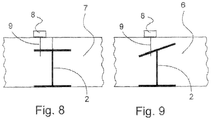
- FIG. 8 there are shown horizontal cross section views of an insulating building system with high wool density insulation panels 7 in figure 8 , and a corresponding building system with low wool density insulation panels 6 in figure 9 .
- a joining profile 2 in a high wool density building system may support an additional building element 8 for instance by nail 9 or screwing engagement without bending, whereas a joining profile in a low wool density building system is prone to bending when support of an additional building element is pursued because low wool density insulation panels 6 provide less support for joining profiles compared to the support provided by high wool density insulation panels 7.
- FIG. 10 a schematic view of an embodiment of an apparatus for producing insulation panels and an edge detail of an insulation panel produced by such an apparatus.
- the apparatus see figure 10 , has a planar work surface 10 and a guiding flange 11 for receiving an insulation panel, which is slideable on the surface 10 along the guiding flange 11.
- the apparatus is provided with a first means 12, such as a rotating cutting blade or a circular saw, for providing a slit 13 in the side of the insulation panel, which slit may fit with a portion of a flange of a joining profile.
- a second cutting means 14 such as a grinding tool for removing material 15 of from the insulation panel.
- insulation material may be removed from the abutment portion of the contact side of the insulation panel.
- a manipulation means 16 such as a compression roller for compressing a profile covering portion to provide a flex zone 5 in said portion.
- the apparatus is adapted for modification of standard sized insulation panels in order to fabricate modified insulation panels having specific dimensions so that the modified insulation panels may fit into specific building structures. This may prove advantageous at the construction site whereto standard sized insulation panels are easily delivered.
Landscapes
- Engineering & Computer Science (AREA)
- Architecture (AREA)
- Civil Engineering (AREA)
- Structural Engineering (AREA)
- Physics & Mathematics (AREA)
- Electromagnetism (AREA)
- Building Environments (AREA)
- Load-Bearing And Curtain Walls (AREA)
- Joining Of Building Structures In Genera (AREA)
- Finishing Walls (AREA)
- Fuel-Injection Apparatus (AREA)
Claims (16)
- Isolierplatte (1) zum Einsetzen zwischen Verbindungsprofilen (2) in einem Rahmenwerk eines isolierenden Gebäudesystems für eine äußere Gebäudestruktur, wobei die Isolierplatte (1) eine Mineralwollplatte ist, die im Wesentlichen parallele erste und zweite Hauptflächen mit im Wesentlichen parallelen, gegenüber angeordneten ersten und zweiten Profilkontaktseiten und im Wesentlichen parallelen, gegenüber angeordneten dritten und vierten Seiten zwischen den Hauptflächen umfasst, wobei die erste und zweite Profilkontaktseite mit einem Längsschlitz versehen ist, der im Wesentlichen zu der ersten Hauptfläche in einem vorgegebenen Abstand davon parallel ist, so dass die erste und zweite Profilkontaktseite mit einem Profilanlageabschnitt und einem Profilabdeckungsabschnitt versehen sind, wobei der Profilabdeckungsabschnitt auf der Seite der Isolierplatte eine komprimierbare Biegezone (5) umfasst, dadurch gekennzeichnet, dass die Biegezone (5) durch Komprimieren während der Herstellung in dem Abschnitt, der sich über den Anlageabschnitt hinaus erstreckt, weniger starr als die übrige Platte gebildet ist, wodurch sie in dieser Zone flexibel gemacht wurde, um eine enge Platte-an-Platte-Passung um ein Verbindungsprofil (2) zu sichern, um bessere Wärmeisolierung zu erlangen; und wobei die Isolierplatte lasttragend und aus Mineralfaserwollmaterial mit einer Dichte zwischen 60-100 kg/m3 hergestellt ist, und dass die Isolierplatte einen Kompressionselastizitätsmodul von wenigstens 500 kPa aufweist, gemessen parallel zur Breite der Isolierplatte.
- Isolierplatte nach Anspruch 1, wobei sich der Profilabdeckungsabschnitt über den Anlageabschnitt von wenigstens einer der Seitenkanten der Isolierplatte (1) hinaus erstreckt.
- Isolierplatte nach einem der vorangehenden Ansprüche, wobei die Isolierplatte (1) mit einer Struktur dualer Dichte versehen ist, so dass die Dichte der Isolierplatte zwischen den Profilabdeckungsabschnitten der zwei Kontaktseiten höher als die Dichte der Isolierplatte zwischen den Profilanlageabschnitten der zwei Kontaktseiten ist.
- Isolierplatte nach einem der vorangehenden Ansprüche, wobei die Isolierplatte eine Gesamtdicke zwischen 75 und 500 mm aufweist.
- Isolierplatte nach einem der vorangehenden Ansprüche, wobei wenigstens die Profilanlageabschnitte der Kontaktseiten mit einer Klebstoffschicht zum Anhaften an dem Profil (2) versehen sind.
- Isolierplatte nach einem der vorangehenden Ansprüche, wobei außerdem Schlitze in oberen und/oder unteren Seitenkanten vorgesehen sind, um einen Flansch von oberen und/oder unteren Rahmenprofilen in der Gebäudestruktur aufzunehmen, um die Isolierplatte darin zu halten.
- Isolierplatte nach einem der Ansprüche 1 bis 6, wobei jede Isolierplatte (1) aus einem Isolierblock besteht.
- Isolierplatte nach einem der Ansprüche 1 bis 7, wobei jede Isolierplatte (1) zwei oder mehr Isolierblöcke umfasst, die in einer gestapelten und/oder geschichteten Konfiguration vorgesehen sind.
- Verfahren zum Herstellen einer Isolierplatte (1) nach einem der vorangehenden Ansprüche, wobei das Verfahren folgende Schritte umfasst:• Bereitstellen einer Isolierplatte (1), die im Wesentlichen parallele erste und zweite Hauptflächen mit im Wesentlichen parallelen, gegenüber angeordneten ersten und zweiten Profilkontaktseiten und im Wesentlichen parallelen, gegenüber angeordneten dritten und vierten Seiten zwischen den Hauptflächen aufweist;• Bereitstellen eines Schlitzes entlang der ersten Kontaktseite in einem vorgegebenen Abstand von der ersten Hauptfläche und im Wesentlichen parallel zu der ersten Hauptfläche, so dass die Kontaktseite mit einem Profilanlageabschnitt und einem Profilabdeckungsabschnitt versehen wird;• Entfernen von Material von dem Anlageabschnitt der Kontaktseite, so dass sich der Profilabdeckungsabschnitt über den Anlageabschnitt der Kontaktseite hinaus erstreckt; und• Komprimieren des sich erstreckenden Profilabdeckungsabschnitts, um in dem Profilabdeckungsabschnitt der ersten Kontaktseite eine Biegezone (5) bereitzustellen, die weniger starr als die übrige Platte ist.
- Verfahren nach Anspruch 9, wobei die Verfahrensschritte für wenigstens die zweite Kontaktseite der Isolierplatte und vorzugsweise auch für die dritte und die vierte Kontaktseite derselben wiederholt werden.
- Verfahren nach Anspruch 9 oder 10, wobei die Schritte im Wesentlichen gleichzeitig ausgeführt werden und/oder wobei die Schritte nacheinander ausgeführt werden.
- Vorrichtung zum Durchführen eines Verfahrens nach einem der Ansprüche 9-11, wobei die Vorrichtung Folgendes umfasst:eine im Wesentlichen ebenflächige Arbeitsfläche (10) mit einem im Wesentlichen senkrechten Führungsflansch (11) zum Aufnehmen einer Isolierplatte (1), die an der Fläche (10) an dem Führungsflansch (11) entlang verschiebbar ist, wobei eine Isolierplattenseite in Kontakt mit dem Flansch (11) steht;ein erstes Mittel (12), wie etwa ein Schneid- oder Schleifmittel, zum Bereitstellen eines Schlitzes (13) in der Seite der Isolierplatte (1), wobei das Mittel an dem Führungsflansch (11) vorgesehen ist;ein zweites Mittel (14), wie etwa ein Schneid- oder Schleifmittel, zum Entfernen von Isoliermaterial (15) von dem Anlageabschnitt der Kontaktseite der Isolationsplatte (1); undein Bearbeitungsmittel (16) zum Komprimieren des sich erstreckenden Profilabdeckungsabschnitts, um eine Biegezone (5) in dem Profilabdeckungsabschnitt der ersten Kontaktseite der Isolierplatte (1) bereitzustellen, die weniger starr als die übrige Platte ist.
- Vorrichtung nach Anspruch 12, wobei das erste Mittel (12) eine drehende Schneidklinge umfasst, die im Wesentlichen parallel zu der Arbeitsfläche in einem vorgegebenen Abstand von der Fläche vorgesehen ist.
- Vorrichtung nach Anspruch 12, wobei das zweite Mittel (14) ein Schleifwerkzeug zum Entfernen von Material (15) von der Seitenkante der Isolierplatte umfasst.
- Vorrichtung nach Anspruch 12, wobei das Bearbeitungsmittel (16) eine Komprimierungswalze umfasst.
- Vorrichtung nach einem der Ansprüche 12-15, wobei das erste Mittel (12), das zweite Mittel (14) und das Bearbeitungsmittel (16) mit einem gemeinsamen Antriebsmittel, wie etwa einer gemeinsamen Antriebswelle, angeordnet sind.
Priority Applications (2)
| Application Number | Priority Date | Filing Date | Title |
|---|---|---|---|
| EP09765810.8A EP2307625B1 (de) | 2008-06-17 | 2009-06-15 | Isolierplatte für ein gebäudesystem und verfahren und vorrichtung zur herstellung solch einer isolierplatte |
| PL09765810T PL2307625T3 (pl) | 2008-06-17 | 2009-06-15 | Panel izolacyjny do systemu budowlanego oraz sposób i urządzenie do produkcji takiego panelu izolacyjnego |
Applications Claiming Priority (3)
| Application Number | Priority Date | Filing Date | Title |
|---|---|---|---|
| EP20080158386 EP2136010A1 (de) | 2008-06-17 | 2008-06-17 | Gebäudesystem für eine Gebäudekonstruktion |
| EP09765810.8A EP2307625B1 (de) | 2008-06-17 | 2009-06-15 | Isolierplatte für ein gebäudesystem und verfahren und vorrichtung zur herstellung solch einer isolierplatte |
| PCT/EP2009/057328 WO2009153230A1 (en) | 2008-06-17 | 2009-06-15 | An insulation panel for a building system and a method and apparatus for producing such insulation panel |
Publications (2)
| Publication Number | Publication Date |
|---|---|
| EP2307625A1 EP2307625A1 (de) | 2011-04-13 |
| EP2307625B1 true EP2307625B1 (de) | 2017-09-20 |
Family
ID=39760788
Family Applications (3)
| Application Number | Title | Priority Date | Filing Date |
|---|---|---|---|
| EP20080158386 Withdrawn EP2136010A1 (de) | 2008-06-17 | 2008-06-17 | Gebäudesystem für eine Gebäudekonstruktion |
| EP09765810.8A Not-in-force EP2307625B1 (de) | 2008-06-17 | 2009-06-15 | Isolierplatte für ein gebäudesystem und verfahren und vorrichtung zur herstellung solch einer isolierplatte |
| EP09765812.4A Not-in-force EP2310587B1 (de) | 2008-06-17 | 2009-06-15 | Isoliergebäudesystem für eine gebäudestruktur |
Family Applications Before (1)
| Application Number | Title | Priority Date | Filing Date |
|---|---|---|---|
| EP20080158386 Withdrawn EP2136010A1 (de) | 2008-06-17 | 2008-06-17 | Gebäudesystem für eine Gebäudekonstruktion |
Family Applications After (1)
| Application Number | Title | Priority Date | Filing Date |
|---|---|---|---|
| EP09765812.4A Not-in-force EP2310587B1 (de) | 2008-06-17 | 2009-06-15 | Isoliergebäudesystem für eine gebäudestruktur |
Country Status (10)
| Country | Link |
|---|---|
| US (2) | US8539733B2 (de) |
| EP (3) | EP2136010A1 (de) |
| CN (2) | CN102112687A (de) |
| CA (2) | CA2726924C (de) |
| DK (2) | DK2307625T3 (de) |
| EA (2) | EA201071341A1 (de) |
| MY (2) | MY157000A (de) |
| PL (2) | PL2310587T3 (de) |
| UA (1) | UA99376C2 (de) |
| WO (4) | WO2009153228A1 (de) |
Families Citing this family (10)
| Publication number | Priority date | Publication date | Assignee | Title |
|---|---|---|---|---|
| EP2136010A1 (de) * | 2008-06-17 | 2009-12-23 | Rockwool International A/S | Gebäudesystem für eine Gebäudekonstruktion |
| WO2017162498A1 (en) | 2016-03-23 | 2017-09-28 | Rockwool International A/S | Prefabricated module for a pitched roof element and pitched roof element for a building roof |
| US9644326B1 (en) * | 2016-07-27 | 2017-05-09 | Gilliam Harris Engineering, LLC | Monolithic paver |
| US9963834B2 (en) | 2016-07-27 | 2018-05-08 | Gilliam Harris Engineering, LLC | Monolithic paver |
| CN112692033B (zh) * | 2020-12-08 | 2021-11-12 | 邢台职业技术学院 | 一种建筑垃圾环保无害处理装置及其处理方法 |
| WO2024223832A1 (en) | 2023-04-28 | 2024-10-31 | Rockwool A/S | Panel-based assembly |
| US12595654B1 (en) * | 2023-06-06 | 2026-04-07 | Lucas E. Patton | Reinforced insulation panel system |
| NL2035689B1 (en) | 2023-08-28 | 2025-03-11 | Well Solutions Bv | Structural panel element production method |
| CN117403807B (zh) * | 2023-10-27 | 2024-04-26 | 海南大学 | 一种质轻、易于预制且方便现场施工的叠合墙 |
| CN118060044B (zh) * | 2024-04-25 | 2024-07-05 | 江苏勤智建设工程有限公司 | 一种建筑工程用建筑垃圾破碎装置 |
Citations (5)
| Publication number | Priority date | Publication date | Assignee | Title |
|---|---|---|---|---|
| DE7304666U (de) * | 1973-02-08 | 1975-02-27 | Rottmann H Elementbau Gmbh | Holzplatte mit einer oder mehreren abgerundeten Kanten oder Flächen |
| DE29808924U1 (de) * | 1998-05-16 | 1998-09-03 | Deutsche Rockwool Mineralwoll-Gmbh, 45966 Gladbeck | Wärmedämmelement |
| WO2004009927A1 (de) * | 2002-07-19 | 2004-01-29 | Deutsche Rockwool Mineralwool Gmbh & Co. Ohg | Dämmschicht aus mineralfasern und gebäudewand |
| EP1655119A1 (de) * | 2004-11-04 | 2006-05-10 | IMA Klessmann GmbH Holzbearbeitungssysteme | Verfahren zum Fertigen von formatierten Leichtbauplatten |
| DE102006038115A1 (de) * | 2006-08-14 | 2008-02-21 | Fritz Egger Gmbh & Co. | Leichtbauplatte |
Family Cites Families (40)
| Publication number | Priority date | Publication date | Assignee | Title |
|---|---|---|---|---|
| US1841785A (en) * | 1930-06-19 | 1932-01-19 | Cellufoam Corp | Method of making layers of distended fibrous materials |
| US2257001A (en) | 1937-12-31 | 1941-09-23 | American Cyanamid & Chem Corp | Building unit and construction |
| US3090699A (en) * | 1960-05-12 | 1963-05-21 | Armstrong Cork Co | Sag-resistant fiberboard and method of making same |
| US4169688A (en) * | 1976-03-15 | 1979-10-02 | Sato Toshio | Artificial skating-rink floor |
| US4062721A (en) * | 1976-10-26 | 1977-12-13 | Conwed Corporation | Use of surfactant to increase water removal from fibrous web |
| US4170859A (en) * | 1977-10-14 | 1979-10-16 | James Counihan | Composite structure and assembly joint for a floor system |
| FR2415696A1 (fr) * | 1978-01-26 | 1979-08-24 | Smac Acieroid | Paroi isolante thermo-acoustique |
| DE7932271U1 (de) | 1979-11-15 | 1980-04-10 | Rigips Baustoffwerke Gmbh & Co Kg, 3452 Bodenwerder | Bauplatte |
| DE3017332A1 (de) * | 1980-05-06 | 1981-11-12 | Masonite AB, Rundviksverken | Bauelement, insbesondere dachbauelement |
| US4682458A (en) * | 1983-10-27 | 1987-07-28 | Trent Jetfloor Limited | Dry laid floors |
| GB2179075A (en) * | 1985-08-12 | 1987-02-25 | Permabond Adhesives | Adhesively bonded structures |
| US4633634A (en) * | 1985-08-30 | 1987-01-06 | Nemmer Albert E | Building side wall construction and panel therefor |
| ZA8864B (en) * | 1987-01-12 | 1988-12-28 | Usg Interiors Inc | Low density mineral wool panel and method |
| US5047120A (en) * | 1988-07-11 | 1991-09-10 | Usg Interiors, Inc. | Method for manufacture of lightweight frothed mineral wool panel |
| US5136822A (en) * | 1989-09-27 | 1992-08-11 | Blum Alan L | Prefabricated building elements |
| US5062250A (en) * | 1990-02-27 | 1991-11-05 | Metal Tech, Inc. | Insulating panel system, panels and connectors therefor |
| US6134861A (en) * | 1996-08-21 | 2000-10-24 | Spude; Gerald T. | Foundation construction method |
| US5992112A (en) * | 1996-08-27 | 1999-11-30 | Josey Industrial Technologies, Inc. | Modular building floor structure |
| SE9701931L (sv) * | 1997-05-23 | 1998-11-24 | Gustav Naeslund | Lättbalk i form av en I-balk av tunnplåt |
| CZ292801B6 (cs) * | 1997-08-07 | 2003-12-17 | Saint-Gobain Isover | Stavební dílec pro obvodové pláště budov, dílcová sestava obsahující stavební dílce, a šroub a deska pro dílcovou sestavu |
| SE511661C2 (sv) | 1998-10-30 | 1999-11-01 | Nordinnovation Ab | Förfarande och profil vid sammansättning av byggblock samt byggblock att sammansättas enligt förfarandet |
| GB0007000D0 (en) * | 2000-03-22 | 2000-05-10 | Int Concept Technologies Nv | Composite building components |
| US6374552B1 (en) * | 2000-04-12 | 2002-04-23 | Alliance Concrete Concepts, Inc. | Skirting wall system |
| US6959520B2 (en) * | 2000-07-03 | 2005-11-01 | Hartman Paul H | Demand side management structures |
| KR100887460B1 (ko) * | 2000-10-10 | 2009-03-10 | 제임스 하디 인터내셔널 파이낸스 비.브이. | 복합 건축 재료 |
| US6620487B1 (en) * | 2000-11-21 | 2003-09-16 | United States Gypsum Company | Structural sheathing panels |
| DE20110293U1 (de) | 2001-05-08 | 2002-09-19 | Deutsche Rockwool Mineralwoll GmbH & Co. oHG, 45966 Gladbeck | Dämmstoffplatte zur Dämmung von Außenwänden aus Profilblechen |
| US6718721B2 (en) | 2001-09-13 | 2004-04-13 | C-Thru Industries, Inc. | Insulated building panels |
| DE10308377A1 (de) * | 2003-02-27 | 2004-10-28 | IsoBouw Dämmtechnik GmbH | Wand- oder Dachelement |
| EP1479825A1 (de) | 2003-05-20 | 2004-11-24 | Loharens Ing.-Bau GmbH | Lärmschutzwandelement |
| SI21513A (sl) * | 2003-06-16 | 2004-12-31 | TERMO, d.d., Industrija termi�nih izolacij, �kofja Loka | Večslojna plošča iz mineralnih vlaken visoke gostote in naprava ter postopek za njeno izdelavo |
| US7677002B2 (en) * | 2004-02-23 | 2010-03-16 | Huber Engineered Woods Llc | Wall sheathing system and method of installation |
| US20060117689A1 (en) * | 2004-11-23 | 2006-06-08 | Shari Howard | Apparatus, system and method of manufacture thereof for insulated structural panels comprising a combination of structural metal channels and rigid foam insulation |
| US7669372B2 (en) * | 2005-02-07 | 2010-03-02 | T. Clear Corporation | Structural insulated panel and panel joint |
| EP1770216A1 (de) * | 2005-09-29 | 2007-04-04 | Rockwool International A/S | Schallabsorbierendes Element und Lärmschutzschirm mit einem solchen Element |
| PL1977054T3 (pl) | 2006-01-26 | 2020-07-27 | Rockwool International A/S | Element warstwowy |
| CA2641755C (en) * | 2006-03-14 | 2011-07-12 | Global Building Systems, Inc. | Building panels with support members extending partially through the panels and method therefor |
| US8561371B2 (en) * | 2006-03-14 | 2013-10-22 | Mute Wall Systems, Inc. | Barrier wall and method of forming wall panels between vertical wall stiffeners with support members extending partially through the wall panels |
| EP2136010A1 (de) * | 2008-06-17 | 2009-12-23 | Rockwool International A/S | Gebäudesystem für eine Gebäudekonstruktion |
| US8161699B2 (en) * | 2008-09-08 | 2012-04-24 | Leblang Dennis William | Building construction using structural insulating core |
-
2008
- 2008-06-17 EP EP20080158386 patent/EP2136010A1/de not_active Withdrawn
-
2009
- 2009-06-15 EP EP09765810.8A patent/EP2307625B1/de not_active Not-in-force
- 2009-06-15 WO PCT/EP2009/057326 patent/WO2009153228A1/en not_active Ceased
- 2009-06-15 EA EA201071341A patent/EA201071341A1/ru unknown
- 2009-06-15 CN CN2009801229462A patent/CN102112687A/zh active Pending
- 2009-06-15 DK DK09765810.8T patent/DK2307625T3/en active
- 2009-06-15 CN CN2009801229477A patent/CN102066672A/zh active Pending
- 2009-06-15 US US12/999,069 patent/US8539733B2/en not_active Expired - Fee Related
- 2009-06-15 EA EA201071334A patent/EA201071334A1/ru unknown
- 2009-06-15 WO PCT/EP2009/057328 patent/WO2009153230A1/en not_active Ceased
- 2009-06-15 CA CA2726924A patent/CA2726924C/en not_active Expired - Fee Related
- 2009-06-15 EP EP09765812.4A patent/EP2310587B1/de not_active Not-in-force
- 2009-06-15 PL PL09765812T patent/PL2310587T3/pl unknown
- 2009-06-15 DK DK09765812.4T patent/DK2310587T3/en active
- 2009-06-15 CA CA2727298A patent/CA2727298C/en not_active Expired - Fee Related
- 2009-06-15 MY MYPI2010005809A patent/MY157000A/en unknown
- 2009-06-15 PL PL09765810T patent/PL2307625T3/pl unknown
- 2009-06-15 US US12/999,331 patent/US8863463B2/en not_active Expired - Fee Related
- 2009-06-15 WO PCT/EP2009/057331 patent/WO2009153232A1/en not_active Ceased
- 2009-06-15 UA UAA201015671A patent/UA99376C2/ru unknown
- 2009-06-15 MY MYPI2010005832A patent/MY156999A/en unknown
- 2009-06-15 WO PCT/EP2009/057333 patent/WO2009153234A1/en not_active Ceased
Patent Citations (5)
| Publication number | Priority date | Publication date | Assignee | Title |
|---|---|---|---|---|
| DE7304666U (de) * | 1973-02-08 | 1975-02-27 | Rottmann H Elementbau Gmbh | Holzplatte mit einer oder mehreren abgerundeten Kanten oder Flächen |
| DE29808924U1 (de) * | 1998-05-16 | 1998-09-03 | Deutsche Rockwool Mineralwoll-Gmbh, 45966 Gladbeck | Wärmedämmelement |
| WO2004009927A1 (de) * | 2002-07-19 | 2004-01-29 | Deutsche Rockwool Mineralwool Gmbh & Co. Ohg | Dämmschicht aus mineralfasern und gebäudewand |
| EP1655119A1 (de) * | 2004-11-04 | 2006-05-10 | IMA Klessmann GmbH Holzbearbeitungssysteme | Verfahren zum Fertigen von formatierten Leichtbauplatten |
| DE102006038115A1 (de) * | 2006-08-14 | 2008-02-21 | Fritz Egger Gmbh & Co. | Leichtbauplatte |
Also Published As
| Publication number | Publication date |
|---|---|
| DK2307625T3 (en) | 2017-12-04 |
| CA2727298A1 (en) | 2009-12-23 |
| US8863463B2 (en) | 2014-10-21 |
| CA2726924C (en) | 2016-08-16 |
| MY156999A (en) | 2016-04-15 |
| US8539733B2 (en) | 2013-09-24 |
| EP2310587A1 (de) | 2011-04-20 |
| US20110107721A1 (en) | 2011-05-12 |
| UA99376C2 (ru) | 2012-08-10 |
| PL2307625T3 (pl) | 2018-02-28 |
| CN102066672A (zh) | 2011-05-18 |
| WO2009153228A1 (en) | 2009-12-23 |
| WO2009153230A1 (en) | 2009-12-23 |
| CA2727298C (en) | 2016-08-16 |
| EP2307625A1 (de) | 2011-04-13 |
| DK2310587T3 (en) | 2017-12-11 |
| EA201071334A1 (ru) | 2011-06-30 |
| CN102112687A (zh) | 2011-06-29 |
| MY157000A (en) | 2016-04-15 |
| EP2136010A1 (de) | 2009-12-23 |
| US20110113724A1 (en) | 2011-05-19 |
| PL2310587T3 (pl) | 2018-02-28 |
| CA2726924A1 (en) | 2009-12-23 |
| EA201071341A1 (ru) | 2011-06-30 |
| WO2009153232A1 (en) | 2009-12-23 |
| WO2009153234A1 (en) | 2009-12-23 |
| EP2310587B1 (de) | 2017-09-20 |
Similar Documents
| Publication | Publication Date | Title |
|---|---|---|
| CA2726924C (en) | An insulation panel for a building system and a method and apparatus for producing such insulation panel | |
| EP1989362B1 (de) | Wärmedämmsystem aus an eine Wand angeordneten miteinander verbundenen Isolierpaneelen | |
| JP7489955B2 (ja) | モジュール式パーティションシステム | |
| US20230383540A1 (en) | Modular Partition System | |
| EP2270287A1 (de) | Bauanordnung mit Eckenprofil für ein isolierendes Bausystem | |
| WO2017101960A1 (en) | Drywall profile for a drywall construction with sound insulation | |
| RU2821878C1 (ru) | Трехслойная панель | |
| EP2773821B1 (de) | Trockenmauerrahmen und trockenmauer mit verbesserten akustischen eigenschaften | |
| JPH0313642A (ja) | 耐火遮音間仕切壁 | |
| JP2026066156A (ja) | 建築用パネル、及び、建築用パネルの製造方法 | |
| WO2022254452A1 (en) | A structural component for supporting construction panels and a wall comprising the same | |
| KR20070095515A (ko) | 단열형 스틸 스터드 |
Legal Events
| Date | Code | Title | Description |
|---|---|---|---|
| PUAI | Public reference made under article 153(3) epc to a published international application that has entered the european phase |
Free format text: ORIGINAL CODE: 0009012 |
|
| 17P | Request for examination filed |
Effective date: 20110113 |
|
| AK | Designated contracting states |
Kind code of ref document: A1 Designated state(s): AT BE BG CH CY CZ DE DK EE ES FI FR GB GR HR HU IE IS IT LI LT LU LV MC MK MT NL NO PL PT RO SE SI SK TR |
|
| AX | Request for extension of the european patent |
Extension state: AL BA RS |
|
| DAX | Request for extension of the european patent (deleted) | ||
| REG | Reference to a national code |
Ref country code: HK Ref legal event code: DE Ref document number: 1159202 Country of ref document: HK |
|
| 17Q | First examination report despatched |
Effective date: 20140219 |
|
| GRAP | Despatch of communication of intention to grant a patent |
Free format text: ORIGINAL CODE: EPIDOSNIGR1 |
|
| INTG | Intention to grant announced |
Effective date: 20170405 |
|
| GRAS | Grant fee paid |
Free format text: ORIGINAL CODE: EPIDOSNIGR3 |
|
| GRAA | (expected) grant |
Free format text: ORIGINAL CODE: 0009210 |
|
| AK | Designated contracting states |
Kind code of ref document: B1 Designated state(s): AT BE BG CH CY CZ DE DK EE ES FI FR GB GR HR HU IE IS IT LI LT LU LV MC MK MT NL NO PL PT RO SE SI SK TR |
|
| REG | Reference to a national code |
Ref country code: GB Ref legal event code: FG4D |
|
| REG | Reference to a national code |
Ref country code: CH Ref legal event code: EP |
|
| REG | Reference to a national code |
Ref country code: AT Ref legal event code: REF Ref document number: 930220 Country of ref document: AT Kind code of ref document: T Effective date: 20171015 |
|
| REG | Reference to a national code |
Ref country code: IE Ref legal event code: FG4D |
|
| REG | Reference to a national code |
Ref country code: DE Ref legal event code: R096 Ref document number: 602009048456 Country of ref document: DE |
|
| REG | Reference to a national code |
Ref country code: DK Ref legal event code: T3 Effective date: 20171128 |
|
| REG | Reference to a national code |
Ref country code: NL Ref legal event code: FP |
|
| PG25 | Lapsed in a contracting state [announced via postgrant information from national office to epo] |
Ref country code: NO Free format text: LAPSE BECAUSE OF FAILURE TO SUBMIT A TRANSLATION OF THE DESCRIPTION OR TO PAY THE FEE WITHIN THE PRESCRIBED TIME-LIMIT Effective date: 20171220 Ref country code: SE Free format text: LAPSE BECAUSE OF FAILURE TO SUBMIT A TRANSLATION OF THE DESCRIPTION OR TO PAY THE FEE WITHIN THE PRESCRIBED TIME-LIMIT Effective date: 20170920 Ref country code: HR Free format text: LAPSE BECAUSE OF FAILURE TO SUBMIT A TRANSLATION OF THE DESCRIPTION OR TO PAY THE FEE WITHIN THE PRESCRIBED TIME-LIMIT Effective date: 20170920 Ref country code: LT Free format text: LAPSE BECAUSE OF FAILURE TO SUBMIT A TRANSLATION OF THE DESCRIPTION OR TO PAY THE FEE WITHIN THE PRESCRIBED TIME-LIMIT Effective date: 20170920 |
|
| REG | Reference to a national code |
Ref country code: LT Ref legal event code: MG4D |
|
| REG | Reference to a national code |
Ref country code: AT Ref legal event code: MK05 Ref document number: 930220 Country of ref document: AT Kind code of ref document: T Effective date: 20170920 |
|
| PG25 | Lapsed in a contracting state [announced via postgrant information from national office to epo] |
Ref country code: LV Free format text: LAPSE BECAUSE OF FAILURE TO SUBMIT A TRANSLATION OF THE DESCRIPTION OR TO PAY THE FEE WITHIN THE PRESCRIBED TIME-LIMIT Effective date: 20170920 Ref country code: GR Free format text: LAPSE BECAUSE OF FAILURE TO SUBMIT A TRANSLATION OF THE DESCRIPTION OR TO PAY THE FEE WITHIN THE PRESCRIBED TIME-LIMIT Effective date: 20171221 Ref country code: BG Free format text: LAPSE BECAUSE OF FAILURE TO SUBMIT A TRANSLATION OF THE DESCRIPTION OR TO PAY THE FEE WITHIN THE PRESCRIBED TIME-LIMIT Effective date: 20171220 |
|
| PG25 | Lapsed in a contracting state [announced via postgrant information from national office to epo] |
Ref country code: ES Free format text: LAPSE BECAUSE OF FAILURE TO SUBMIT A TRANSLATION OF THE DESCRIPTION OR TO PAY THE FEE WITHIN THE PRESCRIBED TIME-LIMIT Effective date: 20170920 Ref country code: CZ Free format text: LAPSE BECAUSE OF FAILURE TO SUBMIT A TRANSLATION OF THE DESCRIPTION OR TO PAY THE FEE WITHIN THE PRESCRIBED TIME-LIMIT Effective date: 20170920 Ref country code: RO Free format text: LAPSE BECAUSE OF FAILURE TO SUBMIT A TRANSLATION OF THE DESCRIPTION OR TO PAY THE FEE WITHIN THE PRESCRIBED TIME-LIMIT Effective date: 20170920 |
|
| PG25 | Lapsed in a contracting state [announced via postgrant information from national office to epo] |
Ref country code: IT Free format text: LAPSE BECAUSE OF FAILURE TO SUBMIT A TRANSLATION OF THE DESCRIPTION OR TO PAY THE FEE WITHIN THE PRESCRIBED TIME-LIMIT Effective date: 20170920 Ref country code: AT Free format text: LAPSE BECAUSE OF FAILURE TO SUBMIT A TRANSLATION OF THE DESCRIPTION OR TO PAY THE FEE WITHIN THE PRESCRIBED TIME-LIMIT Effective date: 20170920 Ref country code: IS Free format text: LAPSE BECAUSE OF FAILURE TO SUBMIT A TRANSLATION OF THE DESCRIPTION OR TO PAY THE FEE WITHIN THE PRESCRIBED TIME-LIMIT Effective date: 20180120 Ref country code: SK Free format text: LAPSE BECAUSE OF FAILURE TO SUBMIT A TRANSLATION OF THE DESCRIPTION OR TO PAY THE FEE WITHIN THE PRESCRIBED TIME-LIMIT Effective date: 20170920 Ref country code: EE Free format text: LAPSE BECAUSE OF FAILURE TO SUBMIT A TRANSLATION OF THE DESCRIPTION OR TO PAY THE FEE WITHIN THE PRESCRIBED TIME-LIMIT Effective date: 20170920 |
|
| REG | Reference to a national code |
Ref country code: DE Ref legal event code: R097 Ref document number: 602009048456 Country of ref document: DE |
|
| PLBE | No opposition filed within time limit |
Free format text: ORIGINAL CODE: 0009261 |
|
| STAA | Information on the status of an ep patent application or granted ep patent |
Free format text: STATUS: NO OPPOSITION FILED WITHIN TIME LIMIT |
|
| 26N | No opposition filed |
Effective date: 20180621 |
|
| PG25 | Lapsed in a contracting state [announced via postgrant information from national office to epo] |
Ref country code: SI Free format text: LAPSE BECAUSE OF FAILURE TO SUBMIT A TRANSLATION OF THE DESCRIPTION OR TO PAY THE FEE WITHIN THE PRESCRIBED TIME-LIMIT Effective date: 20170920 |
|
| REG | Reference to a national code |
Ref country code: HK Ref legal event code: WD Ref document number: 1159202 Country of ref document: HK |
|
| REG | Reference to a national code |
Ref country code: CH Ref legal event code: PL |
|
| GBPC | Gb: european patent ceased through non-payment of renewal fee |
Effective date: 20180615 |
|
| REG | Reference to a national code |
Ref country code: BE Ref legal event code: MM Effective date: 20180630 |
|
| REG | Reference to a national code |
Ref country code: IE Ref legal event code: MM4A |
|
| PG25 | Lapsed in a contracting state [announced via postgrant information from national office to epo] |
Ref country code: MC Free format text: LAPSE BECAUSE OF FAILURE TO SUBMIT A TRANSLATION OF THE DESCRIPTION OR TO PAY THE FEE WITHIN THE PRESCRIBED TIME-LIMIT Effective date: 20170920 Ref country code: LU Free format text: LAPSE BECAUSE OF NON-PAYMENT OF DUE FEES Effective date: 20180615 |
|
| PG25 | Lapsed in a contracting state [announced via postgrant information from national office to epo] |
Ref country code: GB Free format text: LAPSE BECAUSE OF NON-PAYMENT OF DUE FEES Effective date: 20180615 Ref country code: FR Free format text: LAPSE BECAUSE OF NON-PAYMENT OF DUE FEES Effective date: 20180630 Ref country code: IE Free format text: LAPSE BECAUSE OF NON-PAYMENT OF DUE FEES Effective date: 20180615 Ref country code: LI Free format text: LAPSE BECAUSE OF NON-PAYMENT OF DUE FEES Effective date: 20180630 Ref country code: CH Free format text: LAPSE BECAUSE OF NON-PAYMENT OF DUE FEES Effective date: 20180630 |
|
| PG25 | Lapsed in a contracting state [announced via postgrant information from national office to epo] |
Ref country code: BE Free format text: LAPSE BECAUSE OF NON-PAYMENT OF DUE FEES Effective date: 20180630 |
|
| PG25 | Lapsed in a contracting state [announced via postgrant information from national office to epo] |
Ref country code: MT Free format text: LAPSE BECAUSE OF NON-PAYMENT OF DUE FEES Effective date: 20180615 |
|
| PG25 | Lapsed in a contracting state [announced via postgrant information from national office to epo] |
Ref country code: TR Free format text: LAPSE BECAUSE OF FAILURE TO SUBMIT A TRANSLATION OF THE DESCRIPTION OR TO PAY THE FEE WITHIN THE PRESCRIBED TIME-LIMIT Effective date: 20170920 |
|
| PG25 | Lapsed in a contracting state [announced via postgrant information from national office to epo] |
Ref country code: HU Free format text: LAPSE BECAUSE OF FAILURE TO SUBMIT A TRANSLATION OF THE DESCRIPTION OR TO PAY THE FEE WITHIN THE PRESCRIBED TIME-LIMIT; INVALID AB INITIO Effective date: 20090615 Ref country code: PT Free format text: LAPSE BECAUSE OF FAILURE TO SUBMIT A TRANSLATION OF THE DESCRIPTION OR TO PAY THE FEE WITHIN THE PRESCRIBED TIME-LIMIT Effective date: 20170920 |
|
| PG25 | Lapsed in a contracting state [announced via postgrant information from national office to epo] |
Ref country code: MK Free format text: LAPSE BECAUSE OF NON-PAYMENT OF DUE FEES Effective date: 20170920 Ref country code: CY Free format text: LAPSE BECAUSE OF FAILURE TO SUBMIT A TRANSLATION OF THE DESCRIPTION OR TO PAY THE FEE WITHIN THE PRESCRIBED TIME-LIMIT Effective date: 20170920 |
|
| PGFP | Annual fee paid to national office [announced via postgrant information from national office to epo] |
Ref country code: DK Payment date: 20200629 Year of fee payment: 12 Ref country code: FI Payment date: 20200629 Year of fee payment: 12 Ref country code: DE Payment date: 20200629 Year of fee payment: 12 |
|
| PGFP | Annual fee paid to national office [announced via postgrant information from national office to epo] |
Ref country code: NL Payment date: 20200626 Year of fee payment: 12 Ref country code: PL Payment date: 20200519 Year of fee payment: 12 |
|
| REG | Reference to a national code |
Ref country code: DE Ref legal event code: R119 Ref document number: 602009048456 Country of ref document: DE |
|
| REG | Reference to a national code |
Ref country code: FI Ref legal event code: MAE |
|
| REG | Reference to a national code |
Ref country code: DK Ref legal event code: EBP Effective date: 20210630 |
|
| PG25 | Lapsed in a contracting state [announced via postgrant information from national office to epo] |
Ref country code: FI Free format text: LAPSE BECAUSE OF NON-PAYMENT OF DUE FEES Effective date: 20210615 |
|
| REG | Reference to a national code |
Ref country code: NL Ref legal event code: MM Effective date: 20210701 |
|
| PG25 | Lapsed in a contracting state [announced via postgrant information from national office to epo] |
Ref country code: DE Free format text: LAPSE BECAUSE OF NON-PAYMENT OF DUE FEES Effective date: 20220101 |
|
| PG25 | Lapsed in a contracting state [announced via postgrant information from national office to epo] |
Ref country code: NL Free format text: LAPSE BECAUSE OF NON-PAYMENT OF DUE FEES Effective date: 20210701 |
|
| PG25 | Lapsed in a contracting state [announced via postgrant information from national office to epo] |
Ref country code: DK Free format text: LAPSE BECAUSE OF NON-PAYMENT OF DUE FEES Effective date: 20210630 |
|
| PG25 | Lapsed in a contracting state [announced via postgrant information from national office to epo] |
Ref country code: PL Free format text: LAPSE BECAUSE OF NON-PAYMENT OF DUE FEES Effective date: 20210615 |