EP2307724B1 - Noise muffler for compressor and compressor - Google Patents
Noise muffler for compressor and compressor Download PDFInfo
- Publication number
- EP2307724B1 EP2307724B1 EP09765282A EP09765282A EP2307724B1 EP 2307724 B1 EP2307724 B1 EP 2307724B1 EP 09765282 A EP09765282 A EP 09765282A EP 09765282 A EP09765282 A EP 09765282A EP 2307724 B1 EP2307724 B1 EP 2307724B1
- Authority
- EP
- European Patent Office
- Prior art keywords
- flow
- muffler
- compressor
- noise
- duct
- Prior art date
- Legal status (The legal status is an assumption and is not a legal conclusion. Google has not performed a legal analysis and makes no representation as to the accuracy of the status listed.)
- Not-in-force
Links
Images

Classifications
-
- F—MECHANICAL ENGINEERING; LIGHTING; HEATING; WEAPONS; BLASTING
- F04—POSITIVE - DISPLACEMENT MACHINES FOR LIQUIDS; PUMPS FOR LIQUIDS OR ELASTIC FLUIDS
- F04B—POSITIVE-DISPLACEMENT MACHINES FOR LIQUIDS; PUMPS
- F04B53/00—Component parts, details or accessories not provided for in, or of interest apart from, groups F04B1/00 - F04B23/00 or F04B39/00 - F04B47/00
-
- F—MECHANICAL ENGINEERING; LIGHTING; HEATING; WEAPONS; BLASTING
- F04—POSITIVE - DISPLACEMENT MACHINES FOR LIQUIDS; PUMPS FOR LIQUIDS OR ELASTIC FLUIDS
- F04B—POSITIVE-DISPLACEMENT MACHINES FOR LIQUIDS; PUMPS
- F04B39/00—Component parts, details, or accessories, of pumps or pumping systems specially adapted for elastic fluids, not otherwise provided for in, or of interest apart from, groups F04B25/00 - F04B37/00
- F04B39/0027—Pulsation and noise damping means
- F04B39/0055—Pulsation and noise damping means with a special shape of fluid passage, e.g. bends, throttles, diameter changes, pipes
-
- F—MECHANICAL ENGINEERING; LIGHTING; HEATING; WEAPONS; BLASTING
- F01—MACHINES OR ENGINES IN GENERAL; ENGINE PLANTS IN GENERAL; STEAM ENGINES
- F01N—GAS-FLOW SILENCERS OR EXHAUST APPARATUS FOR MACHINES OR ENGINES IN GENERAL; GAS-FLOW SILENCERS OR EXHAUST APPARATUS FOR INTERNAL-COMBUSTION ENGINES
- F01N13/00—Exhaust or silencing apparatus characterised by constructional features
-
- F—MECHANICAL ENGINEERING; LIGHTING; HEATING; WEAPONS; BLASTING
- F01—MACHINES OR ENGINES IN GENERAL; ENGINE PLANTS IN GENERAL; STEAM ENGINES
- F01N—GAS-FLOW SILENCERS OR EXHAUST APPARATUS FOR MACHINES OR ENGINES IN GENERAL; GAS-FLOW SILENCERS OR EXHAUST APPARATUS FOR INTERNAL-COMBUSTION ENGINES
- F01N13/00—Exhaust or silencing apparatus characterised by constructional features
- F01N13/08—Other arrangements or adaptations of exhaust conduits
-
- F—MECHANICAL ENGINEERING; LIGHTING; HEATING; WEAPONS; BLASTING
- F04—POSITIVE - DISPLACEMENT MACHINES FOR LIQUIDS; PUMPS FOR LIQUIDS OR ELASTIC FLUIDS
- F04B—POSITIVE-DISPLACEMENT MACHINES FOR LIQUIDS; PUMPS
- F04B39/00—Component parts, details, or accessories, of pumps or pumping systems specially adapted for elastic fluids, not otherwise provided for in, or of interest apart from, groups F04B25/00 - F04B37/00
-
- F—MECHANICAL ENGINEERING; LIGHTING; HEATING; WEAPONS; BLASTING
- F04—POSITIVE - DISPLACEMENT MACHINES FOR LIQUIDS; PUMPS FOR LIQUIDS OR ELASTIC FLUIDS
- F04B—POSITIVE-DISPLACEMENT MACHINES FOR LIQUIDS; PUMPS
- F04B39/00—Component parts, details, or accessories, of pumps or pumping systems specially adapted for elastic fluids, not otherwise provided for in, or of interest apart from, groups F04B25/00 - F04B37/00
- F04B39/0027—Pulsation and noise damping means
-
- F—MECHANICAL ENGINEERING; LIGHTING; HEATING; WEAPONS; BLASTING
- F04—POSITIVE - DISPLACEMENT MACHINES FOR LIQUIDS; PUMPS FOR LIQUIDS OR ELASTIC FLUIDS
- F04B—POSITIVE-DISPLACEMENT MACHINES FOR LIQUIDS; PUMPS
- F04B39/00—Component parts, details, or accessories, of pumps or pumping systems specially adapted for elastic fluids, not otherwise provided for in, or of interest apart from, groups F04B25/00 - F04B37/00
- F04B39/0027—Pulsation and noise damping means
- F04B39/0055—Pulsation and noise damping means with a special shape of fluid passage, e.g. bends, throttles, diameter changes, pipes
- F04B39/0061—Pulsation and noise damping means with a special shape of fluid passage, e.g. bends, throttles, diameter changes, pipes using muffler volumes
Definitions
- the present invention refers to a noise muffler for refrigeration compressors. More particularly, the invention refers to a noise muffler for compressors used In refrigeration circuits, whose arrangement permits a better ratio between noise dampening and efficiency.
- the present invention further refers to a compressor for refrigeration circuit, having a noise muffler as defined in the present invention.
- suction mufflers The main purpose of suction mufflers is to dampen the noise generated by an intermittent flow, which is inherent to the construction of compressors, and particularly for alternating-type compressors.
- a muffler is used with an arrangement designed for the application of tube combinations and volumes (suction chambers), so that the number and geometry thereof vary in accordance with the frequency level for which Increased dampening is desirable.
- Document US 4,370,104 describes a suction muffler for refrigeration compressors arranged based on two parts, and made of a plastic material. The assembly of the two parts reveals a cylinder-shaped muffler. The muffler is installed, as in other solutions of the state of the art, between the suction tube and the return line of the cooling gas.
- the object of the invention described in this document presents the relative advantage of using insulating material, meaning its heat transfer rate between the compressor parts is lower. In any case, the document does not reveal an optimal solution for noise dampening, maintaining the efficiency of the equipment.
- the hollow body further comprises a deflector element and an inverted T-shaped portion, in order to define the entry and exit parts of the suction chamber.
- the inventions found in the state of the art present constructive aspects that usually do not take into consideration the directing of the flow, or disregard the constructive characteristics whereby it is possible to establish a better balance between noise dampening and compressor performance.
- a first objective of the present invention is to provide a noise muffler for refrigeration compressor, capable of dampening the noise generated by the intermittent flow of the compressor and at the same time a muffler that reduces the loss of load.
- One way of achieving the objective of the present invention is by means of a noise muffler for a refrigeration compressor comprising at least one suction chamber, the suction chamber comprising at least one flow entry channel, the suction chamber comprising at least one flow exit channel.
- the suction chamber comprises at least one directional duct, and the directional duct comprises at least one first end and at least one second end, the directional duct comprising at least one flow control means, the first end comprising an area substantially greater than the second end, the first end being associated to the flow entry channel, the second end being associated to the flow exit channel, the directional duct being capable of directing a preferred flow received at the first end to the second end, the flow control means being capable of offering reduced resistance to the passage of the preferred flow and the flow control means being capable of offering increased resistance in the opposite direction to the passage of the preferred flow.
- a second way of achieving the objective of the present invention is by providing a compressor for a refrigeration circuit, comprising a noise muffler as defined in the present invention.
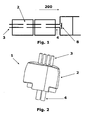
- FIG 1 shows a suction muffler for a refrigeration compressor normally used in the state of the art.
- each suction chamber 2 also called volumes, as well as the tubes that are part of the respective muffler.
- the suction valve 8 is depicted In the same figure.
- the muffler leads to a loss of load in each one of the volumes associated to the refrigeration circuit, and consequently reduces its efficiency.
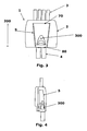
- One of the embodiments of the invention is by way of a noise muffler for refrigeration compressor 1, as illustrated in figures 2 , 3 and 4 .
- the muffler 1 comprises at least one suction chamber 2, and the suction chamber 2 comprises at least one flow entry channel 3.
- Said flow entry channel 3 is a duct whose shape allows the flow of cooling gas on its inside.
- the suction chamber 2 further comprises at least one flow exit channel 4, and the channel 4 is also disposed in the form of a duct.
- the suction chamber 2 comprises at least one directional duct 5, and the directional duct 5 comprises at least one first end 70, and one second end 80, as shown in figure 3 .
- the same figure also shows that the second end 80 of the directional duct 5 is adjacent to the flow exit channel 4.
- the directional duct 5 has a greater passage area than the passage area of the flow entry channel 3, and a greater area than the passage area of the flow exit channel 4.
- Said duct 5 is, in the present invention, substantially aligned with the flow entry channel 3 and with the flow exit channel 4, as illustrated In figure 3 .
- a first end 70 comprises an area substantially greater than the second end 80, giving the duct 5 a trapezoidal shape. Optionally, other shapes can be adopted and implemented. It is important to note that the first end 70 is associated to the flow entry channel 3, and that the second end 80 is associated to the flow exit channel 4.
- the primary characteristic of the directional duct 5 is to develop a convergence of the most part of the flow received in the entry channel 3, to the flow exit channel 4.
- the flow received at the first end 70. and directed to the second end 80, is called the preferred flow 200.
- the duct 5 minimizes the effect of contraction and subsequent expansion of the flow, which is a potential situation for greater loss of load. This approach further allows greater efficiency to be maintained for the whole system.
- Another important characteristic, related to the use of the directional duct 5, is that the flow is substantially confined in a space with additional heat insulation in relation to the outside of the muffler 1, and normally at a higher temperature than the vacuum flow.
- the additional heat insulation is provided by the wall of the directional duct 5 itself.
- the duct 5 is provided, preferably solidarily to the bottom region of the suction muffler 1, with little or no communication area with the inner surface of the suction chamber 2.
- the duct 5 is not solidary to the bottom region of the suction muffler 1.
- Said arrangement favors a confinement of the flow, implying in the maintenance of an average pressure in the antechamber of the suction valve(s).
- a communication between the final section of the directional duct 5, and the inner environment of the suction muffler 1, can be developed in some cases to provide for the drainage of oil potentially carried by the flow, but this communication would cause a restriction upon the greater flow than the passage section of the duct 5.
- the directional duct 5 comprises at least one flow control means 300.
- the flow control means 300 is disposed adjacent to the second end 80.
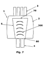
- figure 7 shows in the optional arrangement formed by a plurality of means 300.
- the means 300 are distributed along the directional duct 5.
- Figures 3 and 4 show the allocation of the flow control means 300 in the preferred embodiment.
- the flow control means 300 is capable of offering reduced resistance to the passage of the preferred flow 200, as shown in figure 5 .
- the flow control means 300 offers an increased resistance in the opposite direction to the passage of the preferred flow 200, as illustrated in figure 6 .
- the region contrary to the passage of the preferred flow 200 is also known as the reflux region.
- FIG. 5 further illustrates the flow lines 15 in the preferred condition 200.
- An important aspect in relation to the flow control means 300 is that it has a convex surface in the region downstream of the preferred flow 200, as shown in figures 5 and 6 .
- the same flow control means 300 has a concave surface in the region downstream in the opposite direction to the preferred flow 200.
- the flow control means 300 acts as a flow deflector.
- the flow control means 300 is located substantially near the second end 80 of the directional duct 5, as shown in figures 3 and 4 , but optionally the flow control means 300 can be disposed at a differentiated distance in relation to the second end 80.
- Said arrangement of the flow control means 300 produces a minimum loss of load in the direction of the preferred flow 200, and a substantially larger loss of load in the reflux direction. Consequently, the pressure waves (pulsation) are mitigated by the intermittent working of the valve(s), that is, a greater noise dampening, and the maintenance of a greater pressure in the antechamber of the suction valve(s).
- a loss of load having different characteristics in the flow and reflux conditions occurs due to a recirculation of the current lines, in the reflux condition. Recirculation does not occur in the direction of the preferred flow 200.
- the concavity of the flow control means 300 acts as a barrier to the propagation of pressure waves that form in the reflux condition.
- the present invention preferably refers to the use of a muffler comprised of a single suction chamber 2, but can optionally have mufflers with more than one chamber or volume, applying pairs of directional/deflector ducts in series, between the exit of each volume and the entry of the subsequent volume.
- Figure 7 shows an alternative embodiment, in which it is possible to note the presence of sequential curve deflectors. Said arrangement allows the flow to exit in a preferred direction, as in the preferred embodiment. In this case, the exit is substantially continuous in the flow condition, and has a series of expansions in the reflux condition.
- suction mufflers as described in the present invention, is provided for compressors applied in refrigeration circuits.
Landscapes
- Engineering & Computer Science (AREA)
- Mechanical Engineering (AREA)
- General Engineering & Computer Science (AREA)
- Chemical & Material Sciences (AREA)
- Combustion & Propulsion (AREA)
- Compressor (AREA)
Applications Claiming Priority (2)
| Application Number | Priority Date | Filing Date | Title |
|---|---|---|---|
| BRPI0801890-1A BRPI0801890A2 (pt) | 2008-06-18 | 2008-06-18 | abafador acústico para compressor e compressor |
| PCT/BR2009/000171 WO2009152594A1 (en) | 2008-06-18 | 2009-06-18 | Noise muffler for compressor and compressor |
Publications (2)
| Publication Number | Publication Date |
|---|---|
| EP2307724A1 EP2307724A1 (en) | 2011-04-13 |
| EP2307724B1 true EP2307724B1 (en) | 2012-06-06 |
Family
ID=41056842
Family Applications (1)
| Application Number | Title | Priority Date | Filing Date |
|---|---|---|---|
| EP09765282A Not-in-force EP2307724B1 (en) | 2008-06-18 | 2009-06-18 | Noise muffler for compressor and compressor |
Country Status (8)
| Country | Link |
|---|---|
| US (1) | US9200627B2 (pt) |
| EP (1) | EP2307724B1 (pt) |
| JP (1) | JP5524957B2 (pt) |
| KR (1) | KR101613458B1 (pt) |
| CN (1) | CN102066754B (pt) |
| BR (1) | BRPI0801890A2 (pt) |
| ES (1) | ES2387531T3 (pt) |
| WO (1) | WO2009152594A1 (pt) |
Families Citing this family (8)
| Publication number | Priority date | Publication date | Assignee | Title |
|---|---|---|---|---|
| BRPI1103315B8 (pt) | 2011-07-29 | 2021-09-21 | Embraco Ind De Compressores E Solucoes Em Refrigeracao Ltda | Câmara de sucção |
| US8899378B2 (en) | 2011-09-13 | 2014-12-02 | Black & Decker Inc. | Compressor intake muffler and filter |
| AU2012216658B2 (en) | 2011-09-13 | 2016-09-15 | Black & Decker Inc | Method of reducing air compressor noise |
| EP2706233B1 (en) * | 2012-09-11 | 2021-03-31 | Black & Decker Inc. | Compressor intake muffler and filter |
| CN104832247B (zh) * | 2015-04-29 | 2017-05-03 | 麦克维尔空调制冷(武汉)有限公司 | 一种用于螺杆式机组的排气消声器 |
| US11111913B2 (en) | 2015-10-07 | 2021-09-07 | Black & Decker Inc. | Oil lubricated compressor |
| EP3869040B1 (en) * | 2018-01-12 | 2024-07-31 | LG Electronics Inc. | Linear compressor and refrigerator including same |
| JP2022529231A (ja) * | 2019-03-29 | 2022-06-20 | パナソニック・アプライアンシーズ・リフリジャレーション・デバイシーズ・シンガポール | レシプロ・コンプレッサ用サクション・マフラー |
Family Cites Families (16)
| Publication number | Priority date | Publication date | Assignee | Title |
|---|---|---|---|---|
| DE1157343B (de) * | 1961-08-04 | 1963-11-14 | Danfoss Ved Ing M Clausen | Kolbenverdichter, insbesondere fuer Kleinkaeltemaschinen |
| GB1196176A (en) * | 1966-08-05 | 1970-06-24 | Chiyoda Chem Eng Construct Co | Silencers for Axial - Flow Fluid Fans |
| US4370104A (en) * | 1980-07-22 | 1983-01-25 | White Consolidated Industries, Inc. | Suction muffler for refrigeration compressor |
| IT1147228B (it) * | 1981-02-24 | 1986-11-19 | Necchi Spa | Silenziatore per motocompressore per apparati frigoriferi |
| BR8602173A (pt) * | 1986-05-02 | 1987-12-22 | Brasil Compressores Sa | Aperfeicoamento em sistema de succao de compressor hermetico de refrigeracao |
| BR9102288A (pt) * | 1991-05-28 | 1993-01-05 | Brasileira S A Embraco Empresa | Conjunto abafador de succao para compressor hermetico |
| JPH05126045A (ja) * | 1991-11-05 | 1993-05-21 | Matsushita Refrig Co Ltd | 密閉型圧縮機 |
| US5821475A (en) * | 1994-09-20 | 1998-10-13 | The United States Of America As Represented By The Secretary Of The Navy | Venturi muffler with variable throat area |
| US6012908A (en) * | 1996-01-23 | 2000-01-11 | Matsushita Refrigeration Company | Electrically operated seal compressor having a refrigerant flow branch tube with a chamber disposed in the vicinity of a suction port |
| BR9604126A (pt) * | 1996-08-21 | 1998-05-26 | Brasil Compressores Sa | Amortecedor de sucção para compressor hermético |
| DE10114327C2 (de) * | 2001-03-23 | 2003-07-03 | Danfoss Compressors Gmbh | Saugschalldämpfer |
| BR0105694B1 (pt) * | 2001-10-29 | 2009-05-05 | filtro de sucção para compressor hermético alternativo. | |
| KR100461231B1 (ko) * | 2002-11-28 | 2004-12-17 | 삼성광주전자 주식회사 | 왕복동식 압축기의 흡입 머플러 |
| KR100504983B1 (ko) * | 2003-03-12 | 2005-08-01 | 삼성광주전자 주식회사 | 압축기용 흡입머플러, 압축기 및 냉매순환회로를 가지는장치 |
| DE10323526B3 (de) * | 2003-05-24 | 2005-02-03 | Danfoss Compressors Gmbh | Saugschalldämpfer für einen hermetischen Kältemittelverdichter |
| KR100550536B1 (ko) * | 2003-06-04 | 2006-02-10 | 엘지전자 주식회사 | 리니어 압축기 |
-
2008
- 2008-06-18 BR BRPI0801890-1A patent/BRPI0801890A2/pt not_active IP Right Cessation
-
2009
- 2009-06-18 JP JP2011513828A patent/JP5524957B2/ja not_active Expired - Fee Related
- 2009-06-18 ES ES09765282T patent/ES2387531T3/es active Active
- 2009-06-18 KR KR1020117000826A patent/KR101613458B1/ko not_active Expired - Fee Related
- 2009-06-18 WO PCT/BR2009/000171 patent/WO2009152594A1/en not_active Ceased
- 2009-06-18 EP EP09765282A patent/EP2307724B1/en not_active Not-in-force
- 2009-06-18 CN CN2009801228648A patent/CN102066754B/zh not_active Expired - Fee Related
- 2009-06-18 US US12/997,124 patent/US9200627B2/en not_active Expired - Fee Related
Also Published As
| Publication number | Publication date |
|---|---|
| CN102066754A (zh) | 2011-05-18 |
| JP2011524489A (ja) | 2011-09-01 |
| JP5524957B2 (ja) | 2014-06-18 |
| US9200627B2 (en) | 2015-12-01 |
| ES2387531T3 (es) | 2012-09-25 |
| BRPI0801890A2 (pt) | 2010-02-17 |
| US20110171046A1 (en) | 2011-07-14 |
| KR20110025971A (ko) | 2011-03-14 |
| CN102066754B (zh) | 2013-10-30 |
| EP2307724A1 (en) | 2011-04-13 |
| KR101613458B1 (ko) | 2016-04-19 |
| WO2009152594A1 (en) | 2009-12-23 |
Similar Documents
| Publication | Publication Date | Title |
|---|---|---|
| EP2307724B1 (en) | Noise muffler for compressor and compressor | |
| KR101386479B1 (ko) | 압축기용 머플러 | |
| US7942238B2 (en) | Marine muffler with angularly disposed internal baffle | |
| EP1392974B1 (en) | Suction muffler for a reciprocating hermetic compressor | |
| CN104797820B (zh) | 用于制冷压缩机中的气体的排出的隔热系统和制冷压缩机 | |
| US20130330214A1 (en) | Discharge silencer for a hermetically encapsulated refrigerant compressor | |
| EP2891801B1 (en) | Compressor and valve assembly thereof for reducing pulsation and/or noise | |
| JP4180691B2 (ja) | 圧縮機の消音装置 | |
| JP4888754B2 (ja) | 密閉型コンプレッサ用バルブ装置 | |
| KR100357512B1 (ko) | 압축기의 흡입머플러 | |
| CN212462908U (zh) | 定子及压缩机 | |
| EP1853822B1 (en) | A compressor | |
| EP1853821A2 (en) | A compressor | |
| KR101451655B1 (ko) | 압축기용 머플러 | |
| CN222887085U (zh) | 一种转子压缩机消音器 | |
| CN215409203U (zh) | 压缩机泵体组件、压缩机和空调系统 | |
| CN218882464U (zh) | 制冷压缩机用消音器 | |
| CN222315313U (zh) | 一种全封闭式压缩机的吸气消音器 | |
| CN223868128U (zh) | 一种压缩机排气消音器 | |
| CN216278363U (zh) | 消音器、压缩机以及制冷设备 | |
| KR20150006290A (ko) | 열교환 장치 및 열교환 장치용 케이스 | |
| EP1714033B1 (en) | A compressor | |
| CN120906808A (zh) | 一种压缩机消音结构、压缩机 | |
| CN117685199A (zh) | 一种吸气消音装置及压缩机 | |
| KR20020034234A (ko) | 압축기의 흡입머플러 |
Legal Events
| Date | Code | Title | Description |
|---|---|---|---|
| PUAI | Public reference made under article 153(3) epc to a published international application that has entered the european phase |
Free format text: ORIGINAL CODE: 0009012 |
|
| 17P | Request for examination filed |
Effective date: 20101220 |
|
| AK | Designated contracting states |
Kind code of ref document: A1 Designated state(s): AT BE BG CH CY CZ DE DK EE ES FI FR GB GR HR HU IE IS IT LI LT LU LV MC MK MT NL NO PL PT RO SE SI SK TR |
|
| AX | Request for extension of the european patent |
Extension state: AL BA RS |
|
| RIN1 | Information on inventor provided before grant (corrected) |
Inventor name: FAGOTTI, FABIAN |
|
| DAX | Request for extension of the european patent (deleted) | ||
| GRAP | Despatch of communication of intention to grant a patent |
Free format text: ORIGINAL CODE: EPIDOSNIGR1 |
|
| GRAS | Grant fee paid |
Free format text: ORIGINAL CODE: EPIDOSNIGR3 |
|
| GRAA | (expected) grant |
Free format text: ORIGINAL CODE: 0009210 |
|
| RAP1 | Party data changed (applicant data changed or rights of an application transferred) |
Owner name: WHIRLPOOL S.A. |
|
| AK | Designated contracting states |
Kind code of ref document: B1 Designated state(s): AT BE BG CH CY CZ DE DK EE ES FI FR GB GR HR HU IE IS IT LI LT LU LV MC MK MT NL NO PL PT RO SE SI SK TR |
|
| REG | Reference to a national code |
Ref country code: GB Ref legal event code: FG4D |
|
| REG | Reference to a national code |
Ref country code: CH Ref legal event code: EP Ref country code: AT Ref legal event code: REF Ref document number: 561171 Country of ref document: AT Kind code of ref document: T Effective date: 20120615 |
|
| REG | Reference to a national code |
Ref country code: IE Ref legal event code: FG4D |
|
| REG | Reference to a national code |
Ref country code: DE Ref legal event code: R096 Ref document number: 602009007502 Country of ref document: DE Effective date: 20120802 |
|
| REG | Reference to a national code |
Ref country code: SK Ref legal event code: T3 Ref document number: E 12025 Country of ref document: SK |
|
| REG | Reference to a national code |
Ref country code: ES Ref legal event code: FG2A Ref document number: 2387531 Country of ref document: ES Kind code of ref document: T3 Effective date: 20120925 |
|
| REG | Reference to a national code |
Ref country code: NL Ref legal event code: VDEP Effective date: 20120606 |
|
| PG25 | Lapsed in a contracting state [announced via postgrant information from national office to epo] |
Ref country code: NO Free format text: LAPSE BECAUSE OF FAILURE TO SUBMIT A TRANSLATION OF THE DESCRIPTION OR TO PAY THE FEE WITHIN THE PRESCRIBED TIME-LIMIT Effective date: 20120906 Ref country code: SE Free format text: LAPSE BECAUSE OF FAILURE TO SUBMIT A TRANSLATION OF THE DESCRIPTION OR TO PAY THE FEE WITHIN THE PRESCRIBED TIME-LIMIT Effective date: 20120606 Ref country code: CY Free format text: LAPSE BECAUSE OF FAILURE TO SUBMIT A TRANSLATION OF THE DESCRIPTION OR TO PAY THE FEE WITHIN THE PRESCRIBED TIME-LIMIT Effective date: 20120606 Ref country code: FI Free format text: LAPSE BECAUSE OF FAILURE TO SUBMIT A TRANSLATION OF THE DESCRIPTION OR TO PAY THE FEE WITHIN THE PRESCRIBED TIME-LIMIT Effective date: 20120606 Ref country code: LT Free format text: LAPSE BECAUSE OF FAILURE TO SUBMIT A TRANSLATION OF THE DESCRIPTION OR TO PAY THE FEE WITHIN THE PRESCRIBED TIME-LIMIT Effective date: 20120606 |
|
| REG | Reference to a national code |
Ref country code: LT Ref legal event code: MG4D Effective date: 20120606 |
|
| PG25 | Lapsed in a contracting state [announced via postgrant information from national office to epo] |
Ref country code: LV Free format text: LAPSE BECAUSE OF FAILURE TO SUBMIT A TRANSLATION OF THE DESCRIPTION OR TO PAY THE FEE WITHIN THE PRESCRIBED TIME-LIMIT Effective date: 20120606 Ref country code: HR Free format text: LAPSE BECAUSE OF FAILURE TO SUBMIT A TRANSLATION OF THE DESCRIPTION OR TO PAY THE FEE WITHIN THE PRESCRIBED TIME-LIMIT Effective date: 20120606 Ref country code: SI Free format text: LAPSE BECAUSE OF FAILURE TO SUBMIT A TRANSLATION OF THE DESCRIPTION OR TO PAY THE FEE WITHIN THE PRESCRIBED TIME-LIMIT Effective date: 20120606 |
|
| PG25 | Lapsed in a contracting state [announced via postgrant information from national office to epo] |
Ref country code: NL Free format text: LAPSE BECAUSE OF FAILURE TO SUBMIT A TRANSLATION OF THE DESCRIPTION OR TO PAY THE FEE WITHIN THE PRESCRIBED TIME-LIMIT Effective date: 20120606 Ref country code: BE Free format text: LAPSE BECAUSE OF FAILURE TO SUBMIT A TRANSLATION OF THE DESCRIPTION OR TO PAY THE FEE WITHIN THE PRESCRIBED TIME-LIMIT Effective date: 20120606 Ref country code: EE Free format text: LAPSE BECAUSE OF FAILURE TO SUBMIT A TRANSLATION OF THE DESCRIPTION OR TO PAY THE FEE WITHIN THE PRESCRIBED TIME-LIMIT Effective date: 20120606 Ref country code: MC Free format text: LAPSE BECAUSE OF NON-PAYMENT OF DUE FEES Effective date: 20120630 Ref country code: RO Free format text: LAPSE BECAUSE OF FAILURE TO SUBMIT A TRANSLATION OF THE DESCRIPTION OR TO PAY THE FEE WITHIN THE PRESCRIBED TIME-LIMIT Effective date: 20120606 Ref country code: CZ Free format text: LAPSE BECAUSE OF FAILURE TO SUBMIT A TRANSLATION OF THE DESCRIPTION OR TO PAY THE FEE WITHIN THE PRESCRIBED TIME-LIMIT Effective date: 20120606 Ref country code: IS Free format text: LAPSE BECAUSE OF FAILURE TO SUBMIT A TRANSLATION OF THE DESCRIPTION OR TO PAY THE FEE WITHIN THE PRESCRIBED TIME-LIMIT Effective date: 20121006 |
|
| PG25 | Lapsed in a contracting state [announced via postgrant information from national office to epo] |
Ref country code: PL Free format text: LAPSE BECAUSE OF FAILURE TO SUBMIT A TRANSLATION OF THE DESCRIPTION OR TO PAY THE FEE WITHIN THE PRESCRIBED TIME-LIMIT Effective date: 20120606 Ref country code: PT Free format text: LAPSE BECAUSE OF FAILURE TO SUBMIT A TRANSLATION OF THE DESCRIPTION OR TO PAY THE FEE WITHIN THE PRESCRIBED TIME-LIMIT Effective date: 20121008 Ref country code: MK Free format text: LAPSE BECAUSE OF FAILURE TO SUBMIT A TRANSLATION OF THE DESCRIPTION OR TO PAY THE FEE WITHIN THE PRESCRIBED TIME-LIMIT Effective date: 20120606 |
|
| REG | Reference to a national code |
Ref country code: IE Ref legal event code: MM4A |
|
| REG | Reference to a national code |
Ref country code: DE Ref legal event code: R119 Ref document number: 602009007502 Country of ref document: DE Effective date: 20130101 |
|
| PLBE | No opposition filed within time limit |
Free format text: ORIGINAL CODE: 0009261 |
|
| STAA | Information on the status of an ep patent application or granted ep patent |
Free format text: STATUS: NO OPPOSITION FILED WITHIN TIME LIMIT |
|
| PG25 | Lapsed in a contracting state [announced via postgrant information from national office to epo] |
Ref country code: IE Free format text: LAPSE BECAUSE OF NON-PAYMENT OF DUE FEES Effective date: 20120618 Ref country code: DE Free format text: LAPSE BECAUSE OF NON-PAYMENT OF DUE FEES Effective date: 20130101 Ref country code: DK Free format text: LAPSE BECAUSE OF FAILURE TO SUBMIT A TRANSLATION OF THE DESCRIPTION OR TO PAY THE FEE WITHIN THE PRESCRIBED TIME-LIMIT Effective date: 20120606 |
|
| 26N | No opposition filed |
Effective date: 20130307 |
|
| REG | Reference to a national code |
Ref country code: FR Ref legal event code: ST Effective date: 20130426 |
|
| PG25 | Lapsed in a contracting state [announced via postgrant information from national office to epo] |
Ref country code: BG Free format text: LAPSE BECAUSE OF FAILURE TO SUBMIT A TRANSLATION OF THE DESCRIPTION OR TO PAY THE FEE WITHIN THE PRESCRIBED TIME-LIMIT Effective date: 20120906 Ref country code: MT Free format text: LAPSE BECAUSE OF FAILURE TO SUBMIT A TRANSLATION OF THE DESCRIPTION OR TO PAY THE FEE WITHIN THE PRESCRIBED TIME-LIMIT Effective date: 20120606 |
|
| PG25 | Lapsed in a contracting state [announced via postgrant information from national office to epo] |
Ref country code: FR Free format text: LAPSE BECAUSE OF NON-PAYMENT OF DUE FEES Effective date: 20120806 |
|
| REG | Reference to a national code |
Ref country code: CH Ref legal event code: PL |
|
| GBPC | Gb: european patent ceased through non-payment of renewal fee |
Effective date: 20130618 |
|
| PG25 | Lapsed in a contracting state [announced via postgrant information from national office to epo] |
Ref country code: LI Free format text: LAPSE BECAUSE OF NON-PAYMENT OF DUE FEES Effective date: 20130630 Ref country code: GB Free format text: LAPSE BECAUSE OF NON-PAYMENT OF DUE FEES Effective date: 20130618 Ref country code: CH Free format text: LAPSE BECAUSE OF NON-PAYMENT OF DUE FEES Effective date: 20130630 Ref country code: TR Free format text: LAPSE BECAUSE OF FAILURE TO SUBMIT A TRANSLATION OF THE DESCRIPTION OR TO PAY THE FEE WITHIN THE PRESCRIBED TIME-LIMIT Effective date: 20120606 |
|
| PG25 | Lapsed in a contracting state [announced via postgrant information from national office to epo] |
Ref country code: LU Free format text: LAPSE BECAUSE OF NON-PAYMENT OF DUE FEES Effective date: 20120618 |
|
| PG25 | Lapsed in a contracting state [announced via postgrant information from national office to epo] |
Ref country code: HU Free format text: LAPSE BECAUSE OF FAILURE TO SUBMIT A TRANSLATION OF THE DESCRIPTION OR TO PAY THE FEE WITHIN THE PRESCRIBED TIME-LIMIT Effective date: 20090618 |
|
| PG25 | Lapsed in a contracting state [announced via postgrant information from national office to epo] |
Ref country code: GR Free format text: LAPSE BECAUSE OF FAILURE TO SUBMIT A TRANSLATION OF THE DESCRIPTION OR TO PAY THE FEE WITHIN THE PRESCRIBED TIME-LIMIT Effective date: 20120606 |
|
| PGFP | Annual fee paid to national office [announced via postgrant information from national office to epo] |
Ref country code: AT Payment date: 20150609 Year of fee payment: 7 |
|
| REG | Reference to a national code |
Ref country code: AT Ref legal event code: MM01 Ref document number: 561171 Country of ref document: AT Kind code of ref document: T Effective date: 20160618 |
|
| PG25 | Lapsed in a contracting state [announced via postgrant information from national office to epo] |
Ref country code: AT Free format text: LAPSE BECAUSE OF NON-PAYMENT OF DUE FEES Effective date: 20160618 |
|
| REG | Reference to a national code |
Ref country code: ES Ref legal event code: PC2A Owner name: EMBRACO INDUSTRIA DE COMPRESSORES E SOLUSOES EM RE Effective date: 20190227 |
|
| REG | Reference to a national code |
Ref country code: SK Ref legal event code: PC4A Ref document number: E 12025 Country of ref document: SK Owner name: EMBRACO INDUSTRIA DE COMPRESSORES E SOLUCOES E, BR Free format text: FORMER OWNER: WHIRLPOOL S.A., SAO PAULO SP, BR Effective date: 20190502 |
|
| PGFP | Annual fee paid to national office [announced via postgrant information from national office to epo] |
Ref country code: IT Payment date: 20190621 Year of fee payment: 11 |
|
| PGFP | Annual fee paid to national office [announced via postgrant information from national office to epo] |
Ref country code: SK Payment date: 20190603 Year of fee payment: 11 |
|
| REG | Reference to a national code |
Ref country code: SK Ref legal event code: MM4A Ref document number: E 12025 Country of ref document: SK Effective date: 20200618 |
|
| PG25 | Lapsed in a contracting state [announced via postgrant information from national office to epo] |
Ref country code: SK Free format text: LAPSE BECAUSE OF NON-PAYMENT OF DUE FEES Effective date: 20200618 |
|
| PGFP | Annual fee paid to national office [announced via postgrant information from national office to epo] |
Ref country code: ES Payment date: 20210825 Year of fee payment: 13 |
|
| PG25 | Lapsed in a contracting state [announced via postgrant information from national office to epo] |
Ref country code: IT Free format text: LAPSE BECAUSE OF NON-PAYMENT OF DUE FEES Effective date: 20200618 |
|
| REG | Reference to a national code |
Ref country code: ES Ref legal event code: FD2A Effective date: 20230731 |
|
| PG25 | Lapsed in a contracting state [announced via postgrant information from national office to epo] |
Ref country code: ES Free format text: LAPSE BECAUSE OF NON-PAYMENT OF DUE FEES Effective date: 20220619 |