EP2307762B1 - Transmission variable réversible - rvt - Google Patents
Transmission variable réversible - rvt Download PDFInfo
- Publication number
- EP2307762B1 EP2307762B1 EP08760585.3A EP08760585A EP2307762B1 EP 2307762 B1 EP2307762 B1 EP 2307762B1 EP 08760585 A EP08760585 A EP 08760585A EP 2307762 B1 EP2307762 B1 EP 2307762B1
- Authority
- EP
- European Patent Office
- Prior art keywords
- transmission
- wheel
- pressure
- steering
- planet
- Prior art date
- Legal status (The legal status is an assumption and is not a legal conclusion. Google has not performed a legal analysis and makes no representation as to the accuracy of the status listed.)
- Active
Links
Images








Classifications
-
- F—MECHANICAL ENGINEERING; LIGHTING; HEATING; WEAPONS; BLASTING
- F16—ENGINEERING ELEMENTS AND UNITS; GENERAL MEASURES FOR PRODUCING AND MAINTAINING EFFECTIVE FUNCTIONING OF MACHINES OR INSTALLATIONS; THERMAL INSULATION IN GENERAL
- F16H—GEARING
- F16H15/00—Gearings for conveying rotary motion with variable gear ratio, or for reversing rotary motion, by friction between rotary members
- F16H15/02—Gearings for conveying rotary motion with variable gear ratio, or for reversing rotary motion, by friction between rotary members without members having orbital motion
- F16H15/04—Gearings providing a continuous range of gear ratios
- F16H15/06—Gearings providing a continuous range of gear ratios in which a member A of uniform effective diameter mounted on a shaft may co-operate with different parts of a member B
- F16H15/32—Gearings providing a continuous range of gear ratios in which a member A of uniform effective diameter mounted on a shaft may co-operate with different parts of a member B in which the member B has a curved friction surface formed as a surface of a body of revolution generated by a curve which is neither a circular arc centered on its axis of revolution nor a straight line
- F16H15/36—Gearings providing a continuous range of gear ratios in which a member A of uniform effective diameter mounted on a shaft may co-operate with different parts of a member B in which the member B has a curved friction surface formed as a surface of a body of revolution generated by a curve which is neither a circular arc centered on its axis of revolution nor a straight line with concave friction surface, e.g. a hollow toroid surface
- F16H15/38—Gearings providing a continuous range of gear ratios in which a member A of uniform effective diameter mounted on a shaft may co-operate with different parts of a member B in which the member B has a curved friction surface formed as a surface of a body of revolution generated by a curve which is neither a circular arc centered on its axis of revolution nor a straight line with concave friction surface, e.g. a hollow toroid surface with two members B having hollow toroid surfaces opposite to each other, the member or members A being adjustably mounted between the surfaces
-
- F—MECHANICAL ENGINEERING; LIGHTING; HEATING; WEAPONS; BLASTING
- F16—ENGINEERING ELEMENTS AND UNITS; GENERAL MEASURES FOR PRODUCING AND MAINTAINING EFFECTIVE FUNCTIONING OF MACHINES OR INSTALLATIONS; THERMAL INSULATION IN GENERAL
- F16H—GEARING
- F16H15/00—Gearings for conveying rotary motion with variable gear ratio, or for reversing rotary motion, by friction between rotary members
- F16H15/02—Gearings for conveying rotary motion with variable gear ratio, or for reversing rotary motion, by friction between rotary members without members having orbital motion
- F16H15/04—Gearings providing a continuous range of gear ratios
- F16H15/06—Gearings providing a continuous range of gear ratios in which a member A of uniform effective diameter mounted on a shaft may co-operate with different parts of a member B
- F16H15/32—Gearings providing a continuous range of gear ratios in which a member A of uniform effective diameter mounted on a shaft may co-operate with different parts of a member B in which the member B has a curved friction surface formed as a surface of a body of revolution generated by a curve which is neither a circular arc centered on its axis of revolution nor a straight line
- F16H15/36—Gearings providing a continuous range of gear ratios in which a member A of uniform effective diameter mounted on a shaft may co-operate with different parts of a member B in which the member B has a curved friction surface formed as a surface of a body of revolution generated by a curve which is neither a circular arc centered on its axis of revolution nor a straight line with concave friction surface, e.g. a hollow toroid surface
-
- F—MECHANICAL ENGINEERING; LIGHTING; HEATING; WEAPONS; BLASTING
- F16—ENGINEERING ELEMENTS AND UNITS; GENERAL MEASURES FOR PRODUCING AND MAINTAINING EFFECTIVE FUNCTIONING OF MACHINES OR INSTALLATIONS; THERMAL INSULATION IN GENERAL
- F16H—GEARING
- F16H37/00—Combinations of mechanical gearings, not provided for in groups F16H1/00 - F16H35/00
- F16H37/02—Combinations of mechanical gearings, not provided for in groups F16H1/00 - F16H35/00 comprising essentially only toothed or friction gearings
- F16H37/06—Combinations of mechanical gearings, not provided for in groups F16H1/00 - F16H35/00 comprising essentially only toothed or friction gearings with a plurality of driving or driven shafts; with arrangements for dividing torque between two or more intermediate shafts
- F16H37/08—Combinations of mechanical gearings, not provided for in groups F16H1/00 - F16H35/00 comprising essentially only toothed or friction gearings with a plurality of driving or driven shafts; with arrangements for dividing torque between two or more intermediate shafts with differential gearing
- F16H37/0833—Combinations of mechanical gearings, not provided for in groups F16H1/00 - F16H35/00 comprising essentially only toothed or friction gearings with a plurality of driving or driven shafts; with arrangements for dividing torque between two or more intermediate shafts with differential gearing with arrangements for dividing torque between two or more intermediate shafts, i.e. with two or more internal power paths
- F16H37/084—Combinations of mechanical gearings, not provided for in groups F16H1/00 - F16H35/00 comprising essentially only toothed or friction gearings with a plurality of driving or driven shafts; with arrangements for dividing torque between two or more intermediate shafts with differential gearing with arrangements for dividing torque between two or more intermediate shafts, i.e. with two or more internal power paths at least one power path being a continuously variable transmission, i.e. CVT
- F16H37/086—CVT using two coaxial friction members cooperating with at least one intermediate friction member
Definitions
- the invention relates to the field of gearboxes/transmissions. Especially, the invention provides a new type of reversible variable transmission for vehicles such as cars, busses, trucks, off-road vehicles, lift trucks, telescopic boom handlers and the like. Alternatively, the gearbox can be used in systems such as windmills etc. and other industrial applications that require power to be transferred at variable speeds.
- the ideal car transmission transmits the engine power to the wheels so that for any required power level, the engine works at its highest efficiency point, whatever the car speed.
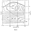
- An engine works at its highest efficiency when the throttle is pushed deeply, as is shown in the graph of Figure 10 showing the specific fuel consumption of a diesel engine.
- the power is modulated rather by changing the engine speed than by changing throttle. For example, driving on a highway at 120 km/h at constant speed requires only about 25 HP.
- the optimum engine speed is then about 1300 RPM for modern engines.
- the required transmission torque ratio is then 0.441, while a typical ratio of an actual gearbox varies from 0.90 to 0.65 in highest ratio.
- Conclusion is that the ratios of the current gearboxes are not high enough for optimum engine efficiency.
- Fig 10 illustrates the statement above.
- the car drives at 120 km/h at 2400 RPM and with 73 Nm from the engine.
- the specific fuel consumption (SFC) is then 265 g/kWh.
- the engine speed must be reduced only to 1700 RPM to obtain the highest efficiency.
- the engine produces then 103 Nm with a SFC of 225 g/kWh.
- This is a fuel saving of 15 %. This is for example a fuel saving from 6.5 l/100km to 5.5 l/100km, only obtained from improving the engine operating point, not considering the efficiency of the transmission.
- the ideal transmission must be environmental friendly, should not contain non-recyclable or toxic materials or oils.
- the ideal efficiency should be 100%, size, weight and cost as low as possible, with perfect reliability and durability.
- a friction wheel differential gear which also uses a driving and a driven wheel and a means for communicating motion from one to another, using a cantilever system.
- Springs are integrated in the cantilever system for compensation of the varying distance between the driving and the driven wheel and to generate the contact pressure between the traction wheels. This construction is too weak to be designed for compact torque transfer.
- the invention provides a reversible variable transmission comprising so-called planetary variators defined below.
- the invention provides a Planetary Variator (13), functioning as subsystem for variable or reversible transmissions, able to vary continuously the transmission ratio, characterized by
- the invention further provides a reversible variable transmission, comprising a primary and a secondary Planetary Variator according to the invention, characterized in that
- the invention further provides a reversible variable transmission according to the invention, further characterized in that
- the invention further provides a reversible variable transmission according to the invention, further characterized in that
- the invention further provides a reversible variable transmission according to the invention, further characterized in that
- the invention further comprises a Hydraulic system, intended to control a reversible variable transmission according to the invention in a car, truck or other on-highway or off-highway vehicle, characterized in that
- the invention further comprises a software program intended to control a reversible variable transmission according to the invention with a hydraulic valve according to the invention in a car, truck or other on-highway or off-highway vehicle, characterized in that
- the invention further provides for the use of a combination of one or more Planetary Variators according to the invention, in different variable transmission layouts, characterized in that
- the invention further provides a reversible variable transmission according to the invention, further characterized in that
- the invention further provides a Planetary Variator according to the invention, further characterized in that
- the invention further provides the use of a transmission according to the invention to transmit power at variable speeds in a car, truck, bus, off-road vehicle, mowing machine, wind turbine, telescopic boom handler, lift truck or any other industrial application in which power needs to be transmitted at variable speeds.
- the invention further provides a (reversible) variable transmission system comprising a transmission of the invention, a hydraulic system according to the invention and a software program according to the invention.
- the transmission of the present invention can be compared best with a toro ⁇ d transmission.
- a half or full toro ⁇ d transmission has the drawbacks that the total spread is limited. It needs also a torque converter or another device for drive away and a shift mechanism and gears for the reverse driving sense.
- the major disadvantage is that the planet wheels and pulleys are rolling over each other with a drilling motion which means that the rolling contacts are by their geometry forced into macroslip while transmitting driving forces. Consequently these rolling contacts must be lubricated to reduce wear and to dissipate the heat.
- the lubricated surfaces have a low friction coefficient. In order to transmit driving forces by the contact surfaces, these surfaces must be pressed against each other with high forces, so that a heavy design is needed. Another consequence of the macroslip is of course the lower efficiency of the transmission.
- a Planetary Variator is a mechanical subsystem, comparable to a planetary gear system, but with a variable ratio and with rolling surfaces instead of gears.
- the Planetary Variator is designed so that in the rolling contacts pure rolling without drilling motion occurs.
- the contact pressure of the rolling contacts is controlled so that the contact stresses stay within the acceptable limits and that the contact pressure is high enough to avoid macroslip.
- Macroslip is a condition where this sub region with a sticking contact is not present. In macroslip condition the magnitude of slip is not controllable.
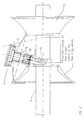
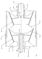
- the Planetary Variator subsystem ( fig. 2 ) is composed of the following parts:
- Ring wheel (1), sun wheel (3) and central shaft (9) all have a common rotational axis.
- the ring wheel (1) is axially compressed against 2 or more planets (2) with a preload force (52).
- the planet wheels (5) can rotate freely around the fork (4) by means of radial bearings (6). Centrifugal forces and forces resulting from the preload force (52) are transferred by the thrust bearing (7) to the planet fork (4).
- Each planet fork (4) can rotate freely around the hinge pins (8) in the plane created by the central shaft (9) and the planet fork (4).
- the hinge axis of each planet (2) crosses the central shaft (9) in the same point.
- the planet wheels (5) are pushed against the sun wheel (3) which delivers the reaction force for the preload force (52).
- the transmission ratio is changed.
- the transverse contact speed and the contact pressure must be controlled in order to keep the transverse and longitudinal creep in the microslip range.
- the active contact surface of both the ring and the sun wheel (1, 3) with the planets (2) is an axisymmetric surface with a special shape.
- the curve of both sun and ring wheel offering rolling without slip can be constructed from its properties in the xy-plane: any tangent of the curve must cross the central x-axis so that the distance from this intersection with the x-axis to the point of tangency is a constant L.
- the intersection point with the x-axis is the position of the hinges.
- this curve is known as the tractrix curve and is described for the first time by Christian Huygens and Claude Perrault in the year 1693. This curve is mostly formulated in a different mathematical expression, but the formula above is more practical for the application in this transmission.
- the surface may deviate slightly from the theoretical one to compensate for compression or wear of the surface.
- the contact surface material, hardness, roughness, condition, coating and the lubrication fluid or gas are selected to optimize traction and wear.
- Such compositions are well known in the art of gear profile technology and machining tools.
- the ring wheel and sun wheel have features to allow or prohibit rotation, to allow or prohibit axial movement and to centre the component, dependent of their function inside the transmission and the type of transmission.
- Some non-limiting examples of different configurations of the ring wheel - planet - sun wheel combinations are depicted in figures 3 and 6-8 .
- the first ring wheel is not capable of rotating, while in alternative embodiments, the ring wheel can be rotating while the planets rolling on to the ring wheel are fixed.
- both the ring wheel and the planets can be rotating independently from each other e.g. at different speeds.
- any configuration is possible, as long as the concept of the axisymmetric contact surfaces of the planets with the ring and sun wheels as outlined above is respected.
- the rotating components are constructed out of steel or hardened steel
- the casing of the transmission can e.g. be Aluminum
- the cover with vanes can e.g. be composed out of Aluminum or plastics. Any other suitable material known in the art of being capable of supporting the needed material hardness, traction requirements and wear resistance can be used.
- the coating of the surface of the interacting surface of the planets and wheels can e.g. be composed out of: AlTiN (Aluminium Titanium Nitride), TiCN (Titanium Carbide Nitride), TiN (Titanium Nitride) or TiCrN (Titanium Chrome Nitride). Any other suitable material known in the art of being capable of supporting the needed material hardness, traction requirements and wear resistance can be used.
- the Planetary Variator has two or more planets (2) for transmission of the driving forces.
- the tangent at the rolling surface crosses the centre of the hinge.
- the distance from the rolling contact point to the hinge equals L: this is the same length L as in the formula of the wheel surface.
- the rolling surface of the planet wheel (5) is crowned to avoid high edge contact stresses. Similar as with the surface of the ring and sun wheel, the contact surface material, hardness, roughness, condition and coating are optimized for traction and wear.
- the forks (4) and hinge pins (8) are designed strong enough to deal with the centrifugal forces, the preload force (52) and the driving moments. On the other hand, the forks (4) may not interfere with each other for all inclination angles of the planets (2).
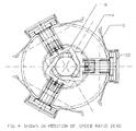
- a design of the forks is shown in fig. 2 , 3 and 4 .
- a 3-dimensional view is shown in figure 13 . All 3 forks of 1 Planetary Variator are the same.
- the 2 legs of the fork (4) are each others mirror picture over the central axis of the fork (4).
- All bearings (6, 7) can be either roller or sliding bearings.
- An oil flow to cool and lubricate the bearings is realized by vanes in the planet wheel (5).
- the planet wheels (5) are always rotating when the engine runs.
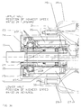
- the pressure relief valve (10) opens below idle speed by centrifugal forces and closes by the spring force before the engine comes to standstill. This valve allows the oil to expand thermally without building up pressure. At standstill it must avoid that oil from the planets (2) contaminates the area of the rolling contacts which will require in general another or no lubrication.
- Alternative lubrication systems are of course possible.
- the use of hybrid roller bearings without lubrication is also possible.
- the Planetary Variator has, similar to a planetary gear system, three interfaces which can be input, output, a connection with the housing, a connection with another Planetary Variator or a connection to other transmission components such as planetary gear sets or offset gearing.
- planetary gear sets or offset gearing.
- Different variable transmission layouts can be built.
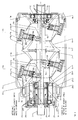
- the engine is directly or via a torsion damper system connected to the transmission input shaft (11).
- This shaft is connected to the central shaft (9a) of the primary Planetary Variator (13a) in such a way that both shafts cannot rotate relatively to one another.
- This central shaft (9a) can slide axially relative to the input shaft (11).
- the central shafts (9a, 9b) of the primary (13a) and the secondary Planetary Variator (13b) are combined into one transmission main shaft (12).
- the ring wheel of the primary Planetary Variator (1 a) is fixed to the housing (14) with two or more locator pins (31) so that it cannot rotate, but only can move axially. It is pushed against the planets (2a) of the primary Planetary Variator by a controlled hydraulic pressure pN. The ring wheel (1 a) moves axially when the transmission ratio changes.
- a torsional vibration damper could be integrated by replacing the locator pins (31) by elastic elements such as springs and damping elements working in tangential direction and mounted between the housing (14) and the primary ring wheel (1a). These elastic elements should then allow a tangential movement of the primary ring wheel (1a) with high stiffness and an axial movement of the primary ring wheel (1 a) with a much lower stiffness.
- the sun wheel (3a) of the primary Planetary Variator is connected as one part with the ring wheel (1b) of the secondary Planetary Variator.
- This combined sun-ring wheel (3a, 1 b) is centered by the planets of the primary and the secondary Planetary Variator (2a, 2b) without bearings for centering.
- radial bushings or bearings (17) could be added between the sun-ring wheel (3a, 1 b) and the main shaft (12).
- the sun-ring wheel (3a, 1 b) moves axially when the ratio changes.
- the planets (2b) of the secondary Planetary Variator are connected also to the main shaft (12).
- the sun wheel (3b) of the secondary Planetary Variator is the output of the transmission. It is axially and radially located by bearings (18, 19). These bearings (18, 19) are selected to transmit the preload force (52) and the axial components of the steering force (53), centrifugal forces and gyroscopic forces acting on the planets (2a, 2b).
- the input shaft (11) is supported by bearing (15) and bearing (16).
- Bearing (15) withstands the axial resultant forces from the centrifugal, gyroscopic, transverse creep and spline friction forces.
- the bearings (15, 16) are housed in the oil distributor (22) which is connected with bolts to the housing (14).
- the input shaft coming from the engine is linked to the main shaft of the transmission by way of a spline-shaft element, allowing translational axional movement, but not rotation relative to each other. This way, the torque from the input shaft (11) is transmitted via the long internal spline to the outer splines of the main shaft (12).
- a spline alternatives which transmit torque and allow axial movement (in the longitudinal direction of the shaft) are possible.
- the main shaft (12) is centered by the bushing (20) inside the input shaft (11) and another bushing (21) in the sun wheel (3b) of the secondary Planetary Variator. These bushings (20, 21) are not loaded by radial forces but must only centre the main shaft (12) and allow an axial movement.
- the first bushing (20) is split to allow mounting over the splines.
- the sun wheel (3b) of the secondary Planetary Variator is supported on two bearings (18, 19). One of them takes the axial loads.
- Lubrication oil for the bearings (15, 16, 18, 19) and bushings (20, 21) is supplied from the housing (14) via bores to the oil distributor (22) over bearing (15) and bearing (16), then the flow splits.
- One part goes through the bushing (20) and the splines and then through the central bore in the main shaft (12).
- the other part by-passes these components over an orifice and joins the first oil flow in the central bore.
- the lube flow goes through bushing (21) and the 2 sun wheel bearings (18, 19).
- the oil flows back via a bore in the housing (14) to the sump.
- the lubrication of the bearings (6a, 6b, 7a, 7b) of each planet is shown as a closed circuit, but alternatively it could be integrated in the lube circuit by an oil flow through channels inside the hinge pins (8a, 8b). This alternative would require seals between the hinge pins (8a, 8b) and the planet fork (4a, 4b).
- the flow is generated by vanes (32) inside the planet wheel (5), pumping the oil outward.
- the planets (2) are also rotating around their axis and thus the oil is circulating through the bearings (6 and 7).
- the design of the lubrication supposes that the lubrication fluid or gas of the rolling contacts must not be mixed with the lubrication oil of the bearings. For this reason, the transmission interior with the rolling contacts is completely sealed from the lubrication oil for the bearings and sealed from the outside of course.
- the housing (14) and the oil distributor (22) contains also 2 more bores for the steering pressures pSF and pSR. These pressures are sealed by 3 piston rings (23) between the oil distributor (22) and the rotating input shaft (11). The leaking oil from the steering pressure over the piston rings (23) is collected in the lube circuit.
- the lube circuit is perfectly sealed to the transmission exterior and to the area of the rolling surfaces by lip seals (24). Via the sealing tube (25) the steering pressures pSF and pSR are sealed and directed to the Forward steering cylinder (26) and the Reverse steering cylinder (27) respectively.
- Bushing (17) is made from material for dry running or running in the gas or fluid for the rolling contacts. In normal operation this bushing (17) is not making contact with the main shaft (12). See section 4.6.1.
- Fig. 5 shows a hydraulic method to generate the preload forces and the steering force, but these forces can also be created by pneumatic or mechanical means.
- a hydraulic controlled pressure is acting on the preload force piston (29) of the ring wheel (1a) of the primary Planetary Variator to create the Normal forces between the planets (2a, 2b) and the ring and sun wheels (1 a, 1 b, 3a, 3b).
- the preload force piston (29) and preload force cylinder (30) are not rotating.
- the Normal force on each contact surface must be large enough so that the longitudinal and the transverse creep in the contact zones remain in microslip. Permanently a much higher pressure than needed would shorten the life of the bearings and the contact surfaces.
- the ratio is controlled by the Forward steering pressure pSF acting on the steering piston (28) in the Forward steering cylinder (26) and by the Reverse steering pressure pSR acting on the other side of the steering piston (28) in the Reverse steering cylinder (27).
- This steering piston (28) and the steering cylinders (26, 27) are rotating with input speed. Without steering pressure, the transmission ratio would go to speed ratio zero because the centrifugal forces on the planets (2a, 2b) pull the main shaft (12) in the position of speed ratio zero.
- the net steering force is controlled by the software.
- Fast downshifting (when driving forward) requires in most cases no hydraulic power from the steering pressure since the centrifugal forces on the planets (2a, 2b) generally are already strong enough to shift down only by diminishing the Forward steering pressure pSF. When the centrifugal forces are not sufficient, fast downshifting is assisted by the Reverse steering pressure pSR.
- the SW must control the preload force pressure and the steering pressures pSF and pSR.
- the inputs for the SW are the throttle position, requested driving sense, input speed, output speed and the engine torque and efficiency map. Possibly the position of the steering piston will be used as feedback signal.
- the requested engine power level is known. It defines with the efficiency map the requested engine speed.
- the SW defines the first proposal for the speed of the steering piston (28) so that the engine speed changes towards the requested engine speed. More in detail the transmission computer calculates the preload force and the steering force in 5 steps in order to prevent that macroslip would occur in one of the rolling contacts and to avoid that the anti-spin control of the car would interfere too often.
- the requested power will be limited by the known value of the tyre grip on dry concrete.
- the PID controller defines then the speed vS of the steering piston (28). Then all geometrical parameters and all internal speeds (longitudinal and transverse on the rolling direction) are calculated. With the actual transmission input torque, the longitudinal forces in the rolling contacts are calculated.
- microslip With the theory of microslip, the longitudinal creep is calculated. If all longitudinal creeps are in microslip, the controller goes to the next step; if not, the input torque must be reduced. (The latter should not occur, since it means that the transmission is under designed.)
- the steering speed vS is already calculated by the controller; the preload pressure pN is assumed to be max.
- the steering speed vS defines also all transverse speeds in the rolling contacts.
- the longitudinal microslip is defined.
- the transverse creep is also defined. Both creeps define the total creep.
- the right preload pressure pN is calculated. (With this calculation sequence, the preload pressure cannot exceed the maximum limit.)
- the steering speed vS When the steering pressure is higher than the limit, the steering speed vS must be reduced and the controller goes back to step 1; if not, the preload pressure pN and the Forward steering pressure pSF are defined to stay within microslip and to use the engine as close as possible to its max efficiency point for the given (changing) power request.
- a preferred hydraulic power supply is shown in fig.5
- a high pressure i.e. 20 to 50 bar
- the needed hydraulic power is around 50 Watt, but during a fast ratio change, a high pressure and a high flow are needed simultaneously during a fraction of a second.
- the hydraulic peak power can rise close to 10 kW.
- the hydraulic pressures pN and pSF are low (around 10 bar) and the needed hydraulic power is less than 5 Watt.
- the oil pump (40) with small displacement is engine driven.
- the hydraulic pump switch (41) is an on-off valve which selects whether the pump (40) supplies power to one of the accumulators (38 or 39) or it drains all pump flow back to the sump and thus consuming almost no power from the engine.
- the hydraulic feed switch (42) selects which accumulator to be filled.
- the high pressure accumulator (39) gets priority over the low pressure accumulator (38).
- the hydraulic accumulator switch (43) selects which accumulator is used as supply for the 3 props: the accumulator with the smallest pressure exceeding the maximum of the required pressures is used.
- Pressure sensors (44) monitoring the accumulator pressures are used as input information for the transmission controller.
- the pressures pN, pSF and pSR are controlled as described above in 4.4.
- the microslip at the rolling surfaces creates heat. At high engine power and high torque ratio more heat is created than what will be transferred to the surrounding gas or fluid. This excess of heat will rise the temperature of the planet, sun and ring wheels. At lower power levels or lower torque ratio the rotating components will cool down by convection to the ambient gas or fluid. Possibly cool fins on the planets and at the inside of the ring and sun wheel can be added to improve the heat transfer.
- This gas or fluid can be an inert gas to avoid corrosion of the steel parts, but it can also be normal air combined with a lubricant or a gas with a mist of a cooling fluid. Cool fins at the inside of the housing will transfer the heat of the internal gas or fluid to the housing.
- the housing itself will be cooled by the driving wind. In some applications or conditions, cooling by convection as described above can be insufficient. In that case a fan blowing the gas or a pump circulating the fluid will be added. Outside the housing the gas or fluid will be cooled. In the same circuit wear particles from the rolling surfaces will be collected in a filter.
- the input shaft 11 drives the primary sun wheel 3a and the secondary ring wheel 1 b.
- the primary planets 2a are connected to the primary central shaft 9a with hinge pins 8 in the same way as in the original design.
- the primary central shaft 9a cannot rotate, but it can be moved axially by the steering forces 53a. These forces control the axial position of the central shaft 9a and thus also the transmission ratio.
- the primary ring wheel 1 a is mechanically connected to the secondary sun wheel 3b via a torque transferring device 47.
- This torque transferring device 47 transmits torque between 2 components but allows an axial displacement between these components. It can be realized by a spline connection, but alternative mechanisms are possible.
- the secondary central shaft 9b is connected to the output shaft 46 with a similar torque transferring device 47.
- this secondary central shaft 9b is positioned axially by steering forces 53b to obtain the required transmission ratio. All contact surfaces of ring wheel 1, planets 2 and sun wheel 3 of the primary and secondary Planetary Variators are pressed against each other in order to transmit torque by friction. This is realized by only one preload force 52 acting over a bearing on the primary ring wheel 1 a. The reaction force is transferred from the secondary sun wheel 3b over a bearing to the housing.
- Fig. 7 shows another alternative design of a reversible transmission.
- the secondary Planetary Variator is replaced by a conventional planetary gear system (with constant transmission ratio).
- the central shaft 9a of the Planetary Variator is stationary and thus no centrifugal forces act on the bearings of the planets 2.
- De highest transmission ratio in both rotation senses of this design is of course lower than in the previous layout of fig. 6 .
- the primary Planetary Variator is equal to the one of fig. 6 .
- the primary ring wheel 1 a is connected to the ring gear 48 over the torque transferring device 47.
- the sun wheel 3a is connected to the sun gear 51. Torque is transferred to the planetary gears 49 driving the planetary gear carrier 50 which is the transmission output.
- a variable transmission with fixed output rotation sense is shown in fig. 8 .
- a random amount of Planetary Variators can be combined in order to obtain a large ratio spread. If the transmission ratio of 1 Planetary Variator varies from r to 1/r, then the total ratio spread for n Planetary Variators becomes r (2n) (in absolute value). In the shown examples r equals about 2.
- the input shaft 11 drives the primary sun wheel 3a. All central shafts 9 of each Planetary Variator are connected. The central shaft 9 cannot rotate but can be positioned by 1 axial steering force 45. All rolling contacts are pressed against each other by applying only one preload force 52 on the output ring wheel 1 b over a bearing. The reaction force is transferred to the housing from the primary sun wheel 3a over a bearing. Because the central shafts 9 do not rotate, there are no centrifugal forces acting on the bearings of the planet wheels 2.
Landscapes
- Engineering & Computer Science (AREA)
- General Engineering & Computer Science (AREA)
- Mechanical Engineering (AREA)
- Friction Gearing (AREA)
- Control Of Transmission Device (AREA)
- Retarders (AREA)
- Electric Propulsion And Braking For Vehicles (AREA)
- Forklifts And Lifting Vehicles (AREA)
Claims (12)
- Variateur planétaire, fonctionnant comme sous-système pour des transmissions variables ou réversible, pouvant faire varier en continu le rapport de transmission,
dans lequel ledit variateur comprend une couronne conique de réduction, deux ou plusieurs satellites montés autour d'un arbre central et un planétaire, de sorte que chaque composant, à savoir couronne conique de réduction, l'arbre central et le planétaire, constitue une interface avec d'autres composants de transmission ;- dans lequel la couronne conique de réduction est un organe axisymétrique autour de l'axe de l'arbre central avec une surface de roulement profilée selon la tractrice et cette surface est de préférence durcie ou revêtue pour résister aux forces de traction et de compression ;- dans lequel le planétaire est pour l'essentiel le même que la couronne conique de réduction, mais les diamètres intérieur et extérieur de la tractrice peuvent différer des diamètres de la couronne conique de réduction ;- dans lequel les satellites comprennent un pignon planétaire ayant une surface de roulement en gros conique, de préférence durcie ou revêtue pour transmettre des forces de traction et de compression, monté en rotation libre autour d'une fourchette planétaire au moyen de roulements ou de coussinets radiaux et axiaux, et le sommet virtuel du cône mentionné coïncide avec l'intersection de l'axe de l'arbre central avec l'axe de la charnière du satellite ;- dans lequel chaque fourchette planétaire d'un variateur planétaire peut tourner librement autour d'un assemblage à charnière dont l'axe est perpendiculaire à l'axe d'arbre central et parallèle au plan du pignon planétaire et chaque fourchette planétaire et chaque pignon planétaire sont conçus pour ne pas interférer l'un avec l'autre pour tous les angles d'inclinaison applicables entre l'axe de satellite et l'axe d'arbre central ;- dans lequel la couronne conique de réduction, les satellites et le planétaire sont pressés les uns contre les autres afin que les surfaces de roulement soient en contact l'une avec l'autre et que les pressions de contact sont suffisamment élevées pour transmettre le couple requis ;- dans lequel les tractrices de la couronne conique de réduction et du planétaire ont toutes deux le même paramètre L de longueur en tant que distance du point de contact roulant du pignon planétaire à l'intersection de l'axe de charnière avec l'axe d'arbre central, où L est utilisé dans l'équation de la tractrice - dans lequel la forme des surfaces de roulement des pignons planétaires, qui est en gros conique, s'écarte légèrement de cette forme théorique de façon convexe afin d'optimiser la répartition des pressions de contact,caractérisé en ce que l'arbre central se déplace axialement à une vitesse définie par rapport à la force de compression et au couple transmis, afin de changer le rapport de transmission.
 - Transmission variable réversible, comprenant un variateur planétaire primaire et un secondaire selon la revendication 1, caractérisée en ce que :- la couronne conique de réduction du variateur planétaire primaire est raccordée au carter de sorte qu'elle ne peut pas tourner mais peut se déplacer axialement sous l'effet d'une force de précharge comprimant tous les contacts roulants des deux variateurs planétaires,- les arbres centraux des deux variateurs planétaire sont combinés en 1 axe principal, raccordés en rotation à l'arbre d'entrée de boîte de vitesses et mobiles axialement sous l'effet d'une force de direction dans les deux sens, alors que l'arbre d'entrée ne se déplace pas axialement,- le planétaire du variateur planétaire primaire est raccordé à la couronne conique de réduction du variateur planétaire secondaire de sorte que la combinaison couronne conique de réduction-planétaire puisse tourner autour de l'axe central de la transmission,
et en ce que- le planétaire du variateur planétaire secondaire est raccordé à l'arbre de sortie de la boîte de vitesses et la force de la réaction de la force de précharge est transférée au carter à travers un palier axial. - Transmission variable réversible selon les revendications 1 et 2, caractérisée en ce que :- les dimensions relatives de la couronne conique de réduction, du planétaire et des satellites sont choisies pour convenir à une application dans une voiture, ce qui signifie que le rapport de vitesse le plus élevé est si élevé que le moteur peut développer sa puissance presque toujours à son point de meilleur rendement, en particulier, les dimensions concernant le rapport de transmission sont les suivantes : diamètre extérieur des couronnes coniques de réduction primaire et secondaire, diamètre intérieur des planétaires primaire et secondaire, diamètre effectif des pignons planétaires, paramètre L de longueur de l'équation de la tractrice ; dans laquelle le rapport de transmission obtenu est par exemple de 2,266 en valeur absolue,- les dimensions relatives de la couronne conique de réduction, du planétaire et des satellites sont choisies pour convenir à une application dans une voiture, ce qui signifie que le rapport de vitesse le plus élevé en marche arrière est suffisamment élevé pour conduire la voiture en marche arrière avec un régime moteur modéré et un bruit faible, en particulier, dans laquelle les dimensions concernant le rapport de transmission en marche arrière sont les suivantes :diamètre intérieur des couronnes coniques de réduction primaire et secondaire, diamètre extérieur des planétaires primaire et secondaire, diamètre effectif des pignons planétaires, paramètre L de longueur de l'équation de la tractrice ; dans laquelle le rapport de transmission obtenu en marche arrière est par exemple de 0,695,et en ce que- en déplaçant l'arbre principal de la boîte de vitesses, le rapport de transmission varie de façon continue entre le rapport de vitesse le plus élevé en marche avant et, en passant par le point mort, le rapport de boîte le plus élevé en marche arrière.
- Transmission variable réversible selon la revendication 2 ou 3, caractérisée en ce que :- la force normale sur chaque contact roulant est créée par une force de précharge, agissant à partir du carter sur la couronne conique de réduction primaire ne tournant pas, en ce que la force de réaction est transférée du planétaire secondaire au carter à travers un palier ;
et en ce que- les forces nettes de direction pour définir la position de l'arbre principal et pour définir le rapport de transmission sont créées par une force dans l'un des deux sens et agissant sur l'arbre principal, et ces forces sont transférées au carter à travers un palier. - Transmission variable réversible selon l'une quelconque des revendications 2 à 4, caractérisée en ce que :- la force de précharge selon la revendication 4 est créée par un ou plusieurs système(s) de piston et cylindre entre le carter et la couronne conique de réduction primaire et activée par une unique pression pneumatique ou hydraulique ou créée par un système mécanique de précharge, ce système mécanique pouvant aussi être utilisé comme frein de stationnement quand on met la boîte de vitesses au point mort ;- la pression de commande est créée par un système piston-cylindre hydraulique ou pneumatique, pouvant fonctionner dans les deux sens, intégré dans l'arbre d'entrée et l'arbre principal ;
et en ce que- la pression hydraulique ou pneumatique pour créer la pression direction selon la revendication 4 est enfermée hermétiquement entre le carter fixe et l'arbre d'entrée tournant par des segments de piston ou des joints conçus pour assurer l'étanchéité de pièces tournant à des vitesses de rotation différentes. - Transmission variable réversible selon l'une quelconque des revendications 2 à 5, comprenant en outre un système hydraulique, destiné à commander ladite transmission variable réversible dans une voiture, un camion ou tout autre véhicule routier ou tout terrain, caractérisé en ce que :- une pompe entraînée par le moteur thermique est utilisée pour fournir la pression et le débit hydrauliques ;- un accumulateur haute pression et un autre basse pression sont intégrés dans le système, dans lequel on utilise le fluide provenant de l'accumulateur basse pression pour mettre sous pression le piston de précharge et le piston de direction prioritairement par rapport à l'accumulateur haute pression ;- la pompe remplit l'accumulateur haute pression prioritairement par rapport à l'accumulateur basse pression ;- on utilise des détendeurs pour commander la pression de précharge et les pressions de direction pour les sens de marche avant et arrière ;- on ajoute éventuellement un dispositif de sécurité utilisant 2 valves de retenue dans la conduite de pression de précharge, sachant que l'une d'elles est commutée par la pression de conduite en marche avant et l'autre par la pression de conduite en marche arrière afin d'évacuer immédiatement la pression de précharge dès qu'une des pressions de direction actives tombe en dessous d'une certaine pression de sollicitation ;
et en ce que- on peut simplifier le dispositif de sécurité susvisé en retirant la valve de retenue de sécurité du schéma hydraulique. - Transmission variable réversible selon la revendication 6, comprenant en outre un système assisté par ordinateur, destiné à commander ladite transmission variable réversible ayant une valve hydraulique dans une voiture, un camion ou tout autre véhicule routier ou tout terrain, caractérisé en ce que :- la courbe du couple moteur en fonction du régime moteur exprimant la consommation minimale de carburant pour chaque niveau de puissance du moteur est stockée dans la mémoire du boîtier électronique de commande ;- le régulateur PID définit la vitesse du piston de direction, raccordé à l'arbre principal, afin d'obtenir le régime moteur égal au régime moteur requis calculé à partir de la courbe de consommation minimale de carburant ;- on peut réduire la vitesse du piston de direction telle que proposée par le régulateur PID pour rester dans la plage de micropatinage sur la base de la procédure de calcul ;
et en ce que- la pression de précharge et la pression de commande déterminant l'angle des satellites par rapport à l'axe de l'arbre principal sont calculées sur la base de la théorie publiée du micropatinage longitudinal et transversal. - Utilisation d'une combinaison d'un ou plusieurs variateurs planétaires selon la revendication 1, dans différentes dispositions de transmission variable, caractérisée en ce que :- chaque interface du variateur planétaire, à savoir la couronne conique de réduction, l'arbre central et le planétaire, peut être raccordée à l'arbre d'entrée, à l'arbre de sortie, au carter, à l'interface avec un autre variateur planétaire ou tout autre composant de transmission tel que pignons décentrés ou systèmes d'engrenage planétaire ;
ou en ce que- on peut réaliser différentes dispositions de transmission variable telles que décrites ci-dessus, dans lesquelles l'expression "réversible" signifie une transmission variable dont le sens de rotation en sortie par rapport au sens de rotation à l'entrée peut être modifié de façon continue et dont le rapport de vitesse est défini, même à régime de sortie très faible ou nul, sans composants de macropatinage tels que convertisseurs de couple ou embrayages à disques de friction. - Transmission variable réversible selon l'une quelconque des revendications 2 à 5, caractérisée en ce que :- l'intérieur de la transmission, où les contacts roulants se déplacent, est rempli d'un gaz inerte, ou d'air normal et d'un fluide projeté pour refroidir et graisser, ou d'un gaz avec un brouillard de liquide de refroidissement ;
et en ce que- ledit intérieur est isolé hermétiquement de l'huile de graissage pour les roulements et de l'extérieur de la transmission. - Variateur planétaire selon la revendication 1 ou transmission variable réversible selon l'une quelconque des revendications 2 à 5, caractérisé en ce que :- la circulation de lubrifiant pour les roulements ou les coussinets à l'intérieur des satellites est éventuellement réalisée par un circuit fermé pour chaque satellite et l'huile est pompée tout autour par des aubes à l'intérieur des satellites, pompant vers l'extérieur l'huile, qui est en outre guidée à travers les roulements ou les coussinets ;- on réalise une variante de circulation de lubrifiant pour les roulements ou les coussinets à l'intérieur des satellites en intégrant cette circulation d'huile dans le circuit principal de graissage comprenant tous les roulements des arbres d'entrée et de sortie, dans lequel le flux est prélevé depuis l'arbre central à travers l'une des articulations, en particulier un des axes de charnière, est guidé à travers les roulements des satellites et retourne par l'autre articulation, en particulier l'autre axe de charnière, dans l'arbre central ;
et en ce que- une autre variante est que les roulements des satellites sont lubrifiés avec de la graisse ou que l'on utilise des paliers hybrides qui n'ont pas besoin d'être lubrifiés. - Utilisation d'une transmission selon l'une quelconque des revendications 2 à 5 pour transmettre une puissance à des régimes variables dans une voiture, un camion, un autobus, un véhicule tout terrain, une tondeuse à gazon, une éolienne, un manipulateur de flèche télescopique, un chariot élévateur ou toute autre application industrielle dans laquelle la puissance a besoin d'être transmise à des régimes variables.
- Système de transmission variable comprenant une transmission selon l'une quelconque des revendications 2 à 7.
Priority Applications (1)
| Application Number | Priority Date | Filing Date | Title |
|---|---|---|---|
| PL08760585.3T PL2307762T3 (pl) | 2008-06-05 | 2008-06-05 | Przekładnia zmienna odwracalna-RVT |
Applications Claiming Priority (1)
| Application Number | Priority Date | Filing Date | Title |
|---|---|---|---|
| PCT/EP2008/057009 WO2009146748A1 (fr) | 2008-06-05 | 2008-06-05 | Transmission variable réversible - rvt |
Publications (3)
| Publication Number | Publication Date |
|---|---|
| EP2307762A1 EP2307762A1 (fr) | 2011-04-13 |
| EP2307762B1 true EP2307762B1 (fr) | 2016-06-01 |
| EP2307762B8 EP2307762B8 (fr) | 2018-05-02 |
Family
ID=40377548
Family Applications (1)
| Application Number | Title | Priority Date | Filing Date |
|---|---|---|---|
| EP08760585.3A Active EP2307762B8 (fr) | 2008-06-05 | 2008-06-05 | Transmission variable réversible - rvt |
Country Status (12)
| Country | Link |
|---|---|
| US (1) | US8512190B2 (fr) |
| EP (1) | EP2307762B8 (fr) |
| JP (1) | JP5467103B2 (fr) |
| KR (1) | KR101289184B1 (fr) |
| CN (1) | CN102066807B (fr) |
| BR (1) | BRPI0822922B8 (fr) |
| CA (1) | CA2724543C (fr) |
| ES (1) | ES2587403T3 (fr) |
| HU (1) | HUE028251T2 (fr) |
| MX (1) | MX2010013178A (fr) |
| PL (1) | PL2307762T3 (fr) |
| WO (1) | WO2009146748A1 (fr) |
Families Citing this family (23)
| Publication number | Priority date | Publication date | Assignee | Title |
|---|---|---|---|---|
| WO2010070962A1 (fr) * | 2008-12-17 | 2010-06-24 | 株式会社小松製作所 | Dispositif de commande pour véhicule à transmission hydrostatique |
| US8267821B2 (en) * | 2009-07-15 | 2012-09-18 | Schaeffler Technologies AG & Co. KG | Mechanical tensioner with damping mechanism |
| DE102011007143A1 (de) * | 2011-04-11 | 2012-10-11 | Zf Friedrichshafen Ag | Vorrichtung mit einer Getriebeeinrichtung zum Versorgen von wenigstens einem Nebenaggregat eines Fahrzeuges mit Antriebsenergie |
| DK2756189T3 (en) * | 2011-10-28 | 2019-04-08 | Rem Tech Inc | Wind turbine gearbox lubrication system |
| GB201223469D0 (en) * | 2012-12-27 | 2013-02-13 | Mazaro Nv | Design features to improve power density and efficiency of a reversible variable transmission - RVT |
| WO2015151193A1 (fr) * | 2014-03-31 | 2015-10-08 | 三菱電機株式会社 | Dispositif de commande de traction de véhicule |
| US9869190B2 (en) | 2014-05-30 | 2018-01-16 | General Electric Company | Variable-pitch rotor with remote counterweights |
| JP6606321B2 (ja) * | 2014-09-29 | 2019-11-13 | オイレス工業株式会社 | 車両用スラスト軸受 |
| US10072510B2 (en) | 2014-11-21 | 2018-09-11 | General Electric Company | Variable pitch fan for gas turbine engine and method of assembling the same |
| US10100653B2 (en) | 2015-10-08 | 2018-10-16 | General Electric Company | Variable pitch fan blade retention system |
| WO2017174106A1 (fr) | 2016-04-04 | 2017-10-12 | Mazaro Nv | Variateur planétaire pour transmission variable |
| US10634071B2 (en) | 2016-04-22 | 2020-04-28 | Paccar Inc | Method of offering finely calibrated engine speed control to a large number of diverse power take-off (PTO) applications |
| CN105840761B (zh) * | 2016-05-18 | 2018-08-24 | 同济大学 | 可自动调速的传动装置及其使用方法 |
| DE102016111740A1 (de) | 2016-06-27 | 2017-12-28 | Volkswagen Aktiengesellschaft | Traktionsgetriebe und Verfahren zu dessen Herstellung |
| DE102016223922A1 (de) | 2016-12-01 | 2018-06-07 | Volkswagen Aktiengesellschaft | Traktionsgetriebe und Antriebseinheit für ein Kraftfahrzeug |
| CN108426011A (zh) * | 2018-03-08 | 2018-08-21 | 徐丰 | 被动偏转多滚轮式无级变速器 |
| KR102084384B1 (ko) * | 2018-11-26 | 2020-03-04 | 현대 파워텍 주식회사 | 토크전달장치 |
| DE102019129918A1 (de) * | 2019-11-06 | 2021-05-06 | Nsk Ltd. | Traktionsgetriebe |
| RS65468B1 (sr) * | 2020-03-30 | 2024-05-31 | Mazaro Nv | Postupak za upravljanje kontinualno varijabilnim menjačem i menjač opremljen upravljačkim sistemom za primenu pomenutog postupka |
| US11598870B2 (en) * | 2021-03-09 | 2023-03-07 | GM Global Technology Operations LLC | Methods, systems, and apparatuses to estimate hitch articulation angle (HAA) using ultra-sonic sensors (USS) and fusion with other sensors |
| US11674435B2 (en) | 2021-06-29 | 2023-06-13 | General Electric Company | Levered counterweight feathering system |
| US11795964B2 (en) | 2021-07-16 | 2023-10-24 | General Electric Company | Levered counterweight feathering system |
| US12601271B2 (en) | 2022-10-21 | 2026-04-14 | General Electric Company | Variable pitch fan of a gas turbine engine |
Family Cites Families (12)
| Publication number | Priority date | Publication date | Assignee | Title |
|---|---|---|---|---|
| GB215209A (en) * | 1923-05-30 | 1924-05-08 | Adolf Gerdes | Variable-speed and reverse gearing |
| US1856383A (en) | 1927-12-23 | 1932-05-03 | Gerdes Adolf Friedrich | Friction-wheel differential gear |
| US4296647A (en) * | 1979-05-30 | 1981-10-27 | Vadetec Corporation | Differential transmission drive unit |
| US4495829A (en) * | 1980-05-19 | 1985-01-29 | Ipanema Company | Power drive line having a wide range of speed ratios |
| US4726244A (en) * | 1986-04-08 | 1988-02-23 | Pencier Robert D De | Reversible continuously variable transmission |
| JPS643228A (en) | 1987-06-25 | 1989-01-09 | Mazda Motor | Manufacture of swirl chamber for internal combustion engine |
| JPH0293559U (fr) * | 1989-01-13 | 1990-07-25 | ||
| JPH09296851A (ja) * | 1996-03-04 | 1997-11-18 | Mitsubishi Heavy Ind Ltd | 可変速動力伝達装置 |
| JPH10169740A (ja) | 1996-12-05 | 1998-06-26 | Koyo Seiko Co Ltd | トロイダル型無段変速機 |
| CN2336137Y (zh) * | 1998-04-23 | 1999-09-01 | 何启勋 | 可逆无级自动变速机构 |
| JP2005291340A (ja) | 2004-03-31 | 2005-10-20 | Nsk Ltd | トロイダル型無段変速機及びその構成部材の製造方法 |
| GR1006039B (el) * | 2006-11-27 | 2008-09-02 | Αντωνιος Μαστροκαλος | Συστημα διευθυνσης τροχοφορων, με πλανητικο συστημα, συνεχους μεταδοσης κινησης μεσω γραναζιων |
-
2008
- 2008-06-05 WO PCT/EP2008/057009 patent/WO2009146748A1/fr not_active Ceased
- 2008-06-05 HU HUE08760585A patent/HUE028251T2/en unknown
- 2008-06-05 PL PL08760585.3T patent/PL2307762T3/pl unknown
- 2008-06-05 JP JP2011511985A patent/JP5467103B2/ja active Active
- 2008-06-05 MX MX2010013178A patent/MX2010013178A/es active IP Right Grant
- 2008-06-05 CA CA2724543A patent/CA2724543C/fr active Active
- 2008-06-05 EP EP08760585.3A patent/EP2307762B8/fr active Active
- 2008-06-05 CN CN200880129585.XA patent/CN102066807B/zh not_active Expired - Fee Related
- 2008-06-05 ES ES08760585.3T patent/ES2587403T3/es active Active
- 2008-06-05 KR KR1020117000174A patent/KR101289184B1/ko not_active Expired - Fee Related
- 2008-06-05 BR BRPI0822922A patent/BRPI0822922B8/pt not_active IP Right Cessation
- 2008-06-05 US US12/995,310 patent/US8512190B2/en active Active
Also Published As
| Publication number | Publication date |
|---|---|
| CN102066807A (zh) | 2011-05-18 |
| ES2587403T3 (es) | 2016-10-24 |
| JP2011522188A (ja) | 2011-07-28 |
| CA2724543C (fr) | 2015-11-03 |
| US8512190B2 (en) | 2013-08-20 |
| JP5467103B2 (ja) | 2014-04-09 |
| BRPI0822922A2 (pt) | 2015-06-23 |
| CA2724543A1 (fr) | 2009-12-10 |
| US20110118071A1 (en) | 2011-05-19 |
| PL2307762T3 (pl) | 2016-12-30 |
| WO2009146748A1 (fr) | 2009-12-10 |
| HUE028251T2 (en) | 2016-12-28 |
| KR20110025816A (ko) | 2011-03-11 |
| MX2010013178A (es) | 2011-04-21 |
| EP2307762B8 (fr) | 2018-05-02 |
| BRPI0822922B1 (pt) | 2019-03-26 |
| KR101289184B1 (ko) | 2013-07-29 |
| CN102066807B (zh) | 2014-05-21 |
| EP2307762A1 (fr) | 2011-04-13 |
| BRPI0822922B8 (pt) | 2023-01-24 |
Similar Documents
| Publication | Publication Date | Title |
|---|---|---|
| EP2307762B1 (fr) | Transmission variable réversible - rvt | |
| JP2011522188A5 (fr) | ||
| EP2938908B1 (fr) | Puissance volumique améliorée d'une transmission variable réversible (rvt) | |
| EP0987459A2 (fr) | Dispositif de friction à disques multiples avec lubrification forcée à la demande | |
| US6001042A (en) | Continuously variable transmission with ratio synchronizing system | |
| US9915330B2 (en) | Four pass torque converter | |
| RU2666026C2 (ru) | Система тяги для гибридных транспортных средств | |
| CN202140522U (zh) | 带式无级变速机构 | |
| RU2465497C2 (ru) | Реверсивная переменная трансмиссия | |
| Parker et al. | Design studies of continuously variable transmissions for electric vehicles | |
| US11718170B2 (en) | Vehicle transmission with disconnect device for power take in | |
| RU199428U1 (ru) | Гидромеханическая передача транспортного средства малой мощности | |
| Carbone et al. | Performance of a city bus equipped with a toroidal traction drive | |
| Genta et al. | Automatic Gearboxes | |
| Groetsch | Paper 7. Automatic Gearboxes with Variable Drive—Mechanical | |
| Fischer et al. | Power Transfer Elements |
Legal Events
| Date | Code | Title | Description |
|---|---|---|---|
| PUAI | Public reference made under article 153(3) epc to a published international application that has entered the european phase |
Free format text: ORIGINAL CODE: 0009012 |
|
| 17P | Request for examination filed |
Effective date: 20101231 |
|
| AK | Designated contracting states |
Kind code of ref document: A1 Designated state(s): AT BE BG CH CY CZ DE DK EE ES FI FR GB GR HR HU IE IS IT LI LT LU LV MC MT NL NO PL PT RO SE SI SK TR |
|
| AX | Request for extension of the european patent |
Extension state: AL BA MK RS |
|
| DAX | Request for extension of the european patent (deleted) | ||
| RAP1 | Party data changed (applicant data changed or rights of an application transferred) |
Owner name: DE MAZIERE, FILIP |
|
| RIN1 | Information on inventor provided before grant (corrected) |
Inventor name: DE MAZIERE, FILIP |
|
| 17Q | First examination report despatched |
Effective date: 20150512 |
|
| GRAP | Despatch of communication of intention to grant a patent |
Free format text: ORIGINAL CODE: EPIDOSNIGR1 |
|
| INTG | Intention to grant announced |
Effective date: 20151223 |
|
| GRAS | Grant fee paid |
Free format text: ORIGINAL CODE: EPIDOSNIGR3 |
|
| GRAA | (expected) grant |
Free format text: ORIGINAL CODE: 0009210 |
|
| AK | Designated contracting states |
Kind code of ref document: B1 Designated state(s): AT BE BG CH CY CZ DE DK EE ES FI FR GB GR HR HU IE IS IT LI LT LU LV MC MT NL NO PL PT RO SE SI SK TR |
|
| REG | Reference to a national code |
Ref country code: GB Ref legal event code: FG4D |
|
| REG | Reference to a national code |
Ref country code: CH Ref legal event code: EP Ref country code: AT Ref legal event code: REF Ref document number: 804079 Country of ref document: AT Kind code of ref document: T Effective date: 20160615 |
|
| REG | Reference to a national code |
Ref country code: IE Ref legal event code: FG4D |
|
| REG | Reference to a national code |
Ref country code: DE Ref legal event code: R096 Ref document number: 602008044527 Country of ref document: DE |
|
| REG | Reference to a national code |
Ref country code: FR Ref legal event code: PLFP Year of fee payment: 9 |
|
| REG | Reference to a national code |
Ref country code: RO Ref legal event code: EPE |
|
| REG | Reference to a national code |
Ref country code: NL Ref legal event code: FP |
|
| REG | Reference to a national code |
Ref country code: SE Ref legal event code: TRGR |
|
| REG | Reference to a national code |
Ref country code: LT Ref legal event code: MG4D |
|
| REG | Reference to a national code |
Ref country code: ES Ref legal event code: FG2A Ref document number: 2587403 Country of ref document: ES Kind code of ref document: T3 Effective date: 20161024 |
|
| PG25 | Lapsed in a contracting state [announced via postgrant information from national office to epo] |
Ref country code: NO Free format text: LAPSE BECAUSE OF FAILURE TO SUBMIT A TRANSLATION OF THE DESCRIPTION OR TO PAY THE FEE WITHIN THE PRESCRIBED TIME-LIMIT Effective date: 20160901 Ref country code: LT Free format text: LAPSE BECAUSE OF FAILURE TO SUBMIT A TRANSLATION OF THE DESCRIPTION OR TO PAY THE FEE WITHIN THE PRESCRIBED TIME-LIMIT Effective date: 20160601 Ref country code: FI Free format text: LAPSE BECAUSE OF FAILURE TO SUBMIT A TRANSLATION OF THE DESCRIPTION OR TO PAY THE FEE WITHIN THE PRESCRIBED TIME-LIMIT Effective date: 20160601 |
|
| PG25 | Lapsed in a contracting state [announced via postgrant information from national office to epo] |
Ref country code: GR Free format text: LAPSE BECAUSE OF FAILURE TO SUBMIT A TRANSLATION OF THE DESCRIPTION OR TO PAY THE FEE WITHIN THE PRESCRIBED TIME-LIMIT Effective date: 20160902 Ref country code: LV Free format text: LAPSE BECAUSE OF FAILURE TO SUBMIT A TRANSLATION OF THE DESCRIPTION OR TO PAY THE FEE WITHIN THE PRESCRIBED TIME-LIMIT Effective date: 20160601 Ref country code: HR Free format text: LAPSE BECAUSE OF FAILURE TO SUBMIT A TRANSLATION OF THE DESCRIPTION OR TO PAY THE FEE WITHIN THE PRESCRIBED TIME-LIMIT Effective date: 20160601 |
|
| REG | Reference to a national code |
Ref country code: HU Ref legal event code: AG4A Ref document number: E028251 Country of ref document: HU |
|
| PG25 | Lapsed in a contracting state [announced via postgrant information from national office to epo] |
Ref country code: IS Free format text: LAPSE BECAUSE OF FAILURE TO SUBMIT A TRANSLATION OF THE DESCRIPTION OR TO PAY THE FEE WITHIN THE PRESCRIBED TIME-LIMIT Effective date: 20161001 Ref country code: EE Free format text: LAPSE BECAUSE OF FAILURE TO SUBMIT A TRANSLATION OF THE DESCRIPTION OR TO PAY THE FEE WITHIN THE PRESCRIBED TIME-LIMIT Effective date: 20160601 |
|
| PG25 | Lapsed in a contracting state [announced via postgrant information from national office to epo] |
Ref country code: PT Free format text: LAPSE BECAUSE OF FAILURE TO SUBMIT A TRANSLATION OF THE DESCRIPTION OR TO PAY THE FEE WITHIN THE PRESCRIBED TIME-LIMIT Effective date: 20161003 |
|
| REG | Reference to a national code |
Ref country code: DE Ref legal event code: R097 Ref document number: 602008044527 Country of ref document: DE |
|
| PLBE | No opposition filed within time limit |
Free format text: ORIGINAL CODE: 0009261 |
|
| 26N | No opposition filed |
Effective date: 20170302 |
|
| PG25 | Lapsed in a contracting state [announced via postgrant information from national office to epo] |
Ref country code: SI Free format text: LAPSE BECAUSE OF FAILURE TO SUBMIT A TRANSLATION OF THE DESCRIPTION OR TO PAY THE FEE WITHIN THE PRESCRIBED TIME-LIMIT Effective date: 20160601 Ref country code: DK Free format text: LAPSE BECAUSE OF FAILURE TO SUBMIT A TRANSLATION OF THE DESCRIPTION OR TO PAY THE FEE WITHIN THE PRESCRIBED TIME-LIMIT Effective date: 20160601 |
|
| REG | Reference to a national code |
Ref country code: FR Ref legal event code: PLFP Year of fee payment: 10 |
|
| GRAM | Information related to correction after decision after decision to grant or to maintain patent in amended form deleted |
Free format text: ORIGINAL CODE: EPIDOSDCDEC |
|
| GRAT | Correction requested after decision to grant or after decision to maintain patent in amended form |
Free format text: ORIGINAL CODE: EPIDOSNCDEC |
|
| PLAA | Information modified related to event that no opposition was filed |
Free format text: ORIGINAL CODE: 0009299DELT |
|
| PLBE | No opposition filed within time limit |
Free format text: ORIGINAL CODE: 0009261 |
|
| GRAT | Correction requested after decision to grant or after decision to maintain patent in amended form |
Free format text: ORIGINAL CODE: EPIDOSNCDEC |
|
| REG | Reference to a national code |
Ref country code: BE Ref legal event code: FP Effective date: 20160809 Ref country code: BE Ref legal event code: PD Owner name: MAZARO NV; BE Free format text: DETAILS ASSIGNMENT: CHANGE OF OWNER(S), AUTRE, MODIFICATION DE L'OEB; FORMER OWNER NAME: DE MAZIERE, FILIP Effective date: 20180403 |
|
| R26N | No opposition filed (corrected) |
Effective date: 20170302 |
|
| RAP2 | Party data changed (patent owner data changed or rights of a patent transferred) |
Owner name: MAZARO NV |
|
| PG25 | Lapsed in a contracting state [announced via postgrant information from national office to epo] |
Ref country code: CY Free format text: LAPSE BECAUSE OF FAILURE TO SUBMIT A TRANSLATION OF THE DESCRIPTION OR TO PAY THE FEE WITHIN THE PRESCRIBED TIME-LIMIT Effective date: 20160601 |
|
| REG | Reference to a national code |
Ref country code: FR Ref legal event code: PLFP Year of fee payment: 11 |
|
| PG25 | Lapsed in a contracting state [announced via postgrant information from national office to epo] |
Ref country code: MT Free format text: LAPSE BECAUSE OF NON-PAYMENT OF DUE FEES Effective date: 20160630 |
|
| REG | Reference to a national code |
Ref country code: CH Ref legal event code: PUE Owner name: MAZARO NV, BE Free format text: FORMER OWNER: DE MAZIERE, FILIP, BE |
|
| PG25 | Lapsed in a contracting state [announced via postgrant information from national office to epo] |
Ref country code: BG Free format text: LAPSE BECAUSE OF FAILURE TO SUBMIT A TRANSLATION OF THE DESCRIPTION OR TO PAY THE FEE WITHIN THE PRESCRIBED TIME-LIMIT Effective date: 20160601 |
|
| PGFP | Annual fee paid to national office [announced via postgrant information from national office to epo] |
Ref country code: IE Payment date: 20180621 Year of fee payment: 11 Ref country code: LU Payment date: 20180620 Year of fee payment: 11 Ref country code: MC Payment date: 20180618 Year of fee payment: 11 |
|
| REG | Reference to a national code |
Ref country code: SK Ref legal event code: TB4A Ref document number: E 22034 Country of ref document: SK Free format text: CORRECTION TO GAZETTE 1/2017 - SC4A, PAGE 84 CAST:(73) MAZARO NV, HEUSDEN (DESTELBERGEN), BE |
|
| REG | Reference to a national code |
Ref country code: AT Ref legal event code: UEP Ref document number: 804079 Country of ref document: AT Kind code of ref document: T Effective date: 20160601 |
|
| PG25 | Lapsed in a contracting state [announced via postgrant information from national office to epo] |
Ref country code: MC Free format text: LAPSE BECAUSE OF NON-PAYMENT OF DUE FEES Effective date: 20190701 |
|
| PG25 | Lapsed in a contracting state [announced via postgrant information from national office to epo] |
Ref country code: IE Free format text: LAPSE BECAUSE OF NON-PAYMENT OF DUE FEES Effective date: 20190605 |
|
| PG25 | Lapsed in a contracting state [announced via postgrant information from national office to epo] |
Ref country code: LU Free format text: LAPSE BECAUSE OF NON-PAYMENT OF DUE FEES Effective date: 20190605 |
|
| P01 | Opt-out of the competence of the unified patent court (upc) registered |
Effective date: 20230328 |
|
| PGFP | Annual fee paid to national office [announced via postgrant information from national office to epo] |
Ref country code: AT Payment date: 20230703 Year of fee payment: 16 |
|
| PGFP | Annual fee paid to national office [announced via postgrant information from national office to epo] |
Ref country code: RO Payment date: 20230711 Year of fee payment: 16 Ref country code: CH Payment date: 20230719 Year of fee payment: 16 |
|
| PGFP | Annual fee paid to national office [announced via postgrant information from national office to epo] |
Ref country code: SK Payment date: 20230710 Year of fee payment: 16 Ref country code: PL Payment date: 20230711 Year of fee payment: 16 Ref country code: HU Payment date: 20230721 Year of fee payment: 16 |
|
| REG | Reference to a national code |
Ref country code: SK Ref legal event code: MM4A Ref document number: E 22034 Country of ref document: SK Effective date: 20240605 |
|
| PG25 | Lapsed in a contracting state [announced via postgrant information from national office to epo] |
Ref country code: RO Free format text: LAPSE BECAUSE OF NON-PAYMENT OF DUE FEES Effective date: 20240605 |
|
| PG25 | Lapsed in a contracting state [announced via postgrant information from national office to epo] |
Ref country code: RO Free format text: LAPSE BECAUSE OF NON-PAYMENT OF DUE FEES Effective date: 20240605 |
|
| REG | Reference to a national code |
Ref country code: CH Ref legal event code: PL |
|
| REG | Reference to a national code |
Ref country code: AT Ref legal event code: MM01 Ref document number: 804079 Country of ref document: AT Kind code of ref document: T Effective date: 20240605 |
|
| PG25 | Lapsed in a contracting state [announced via postgrant information from national office to epo] |
Ref country code: HU Free format text: LAPSE BECAUSE OF NON-PAYMENT OF DUE FEES Effective date: 20240606 |
|
| PG25 | Lapsed in a contracting state [announced via postgrant information from national office to epo] |
Ref country code: AT Free format text: LAPSE BECAUSE OF NON-PAYMENT OF DUE FEES Effective date: 20240605 Ref country code: CH Free format text: LAPSE BECAUSE OF NON-PAYMENT OF DUE FEES Effective date: 20240630 |
|
| PG25 | Lapsed in a contracting state [announced via postgrant information from national office to epo] |
Ref country code: SK Free format text: LAPSE BECAUSE OF NON-PAYMENT OF DUE FEES Effective date: 20240605 |
|
| PGFP | Annual fee paid to national office [announced via postgrant information from national office to epo] |
Ref country code: DE Payment date: 20250618 Year of fee payment: 18 |
|
| PGFP | Annual fee paid to national office [announced via postgrant information from national office to epo] |
Ref country code: GB Payment date: 20250618 Year of fee payment: 18 |
|
| PGFP | Annual fee paid to national office [announced via postgrant information from national office to epo] |
Ref country code: NL Payment date: 20250618 Year of fee payment: 18 Ref country code: BE Payment date: 20250618 Year of fee payment: 18 |
|
| PGFP | Annual fee paid to national office [announced via postgrant information from national office to epo] |
Ref country code: FR Payment date: 20250624 Year of fee payment: 18 |
|
| PGFP | Annual fee paid to national office [announced via postgrant information from national office to epo] |
Ref country code: TR Payment date: 20250602 Year of fee payment: 18 |
|
| PGFP | Annual fee paid to national office [announced via postgrant information from national office to epo] |
Ref country code: CZ Payment date: 20250529 Year of fee payment: 18 |
|
| PGFP | Annual fee paid to national office [announced via postgrant information from national office to epo] |
Ref country code: SE Payment date: 20250618 Year of fee payment: 18 |
|
| PGFP | Annual fee paid to national office [announced via postgrant information from national office to epo] |
Ref country code: ES Payment date: 20250728 Year of fee payment: 18 |
|
| PG25 | Lapsed in a contracting state [announced via postgrant information from national office to epo] |
Ref country code: PL Free format text: LAPSE BECAUSE OF NON-PAYMENT OF DUE FEES Effective date: 20240605 |
|
| PGFP | Annual fee paid to national office [announced via postgrant information from national office to epo] |
Ref country code: IT Payment date: 20250624 Year of fee payment: 18 |