EP2307782B1 - Système de raccordement étanche d ensembles vanne à leur conduit respectif, en particulier destiné à être utilisé avec des gaz combustibles - Google Patents
Système de raccordement étanche d ensembles vanne à leur conduit respectif, en particulier destiné à être utilisé avec des gaz combustibles Download PDFInfo
- Publication number
- EP2307782B1 EP2307782B1 EP09787771A EP09787771A EP2307782B1 EP 2307782 B1 EP2307782 B1 EP 2307782B1 EP 09787771 A EP09787771 A EP 09787771A EP 09787771 A EP09787771 A EP 09787771A EP 2307782 B1 EP2307782 B1 EP 2307782B1
- Authority
- EP
- European Patent Office
- Prior art keywords
- pipe
- attachment element
- valve unit
- pair
- connection
- Prior art date
- Legal status (The legal status is an assumption and is not a legal conclusion. Google has not performed a legal analysis and makes no representation as to the accuracy of the status listed.)
- Not-in-force
Links
Images

Classifications
-
- F—MECHANICAL ENGINEERING; LIGHTING; HEATING; WEAPONS; BLASTING
- F16—ENGINEERING ELEMENTS AND UNITS; GENERAL MEASURES FOR PRODUCING AND MAINTAINING EFFECTIVE FUNCTIONING OF MACHINES OR INSTALLATIONS; THERMAL INSULATION IN GENERAL
- F16L—PIPES; JOINTS OR FITTINGS FOR PIPES; SUPPORTS FOR PIPES, CABLES OR PROTECTIVE TUBING; MEANS FOR THERMAL INSULATION IN GENERAL
- F16L37/00—Couplings of the quick-acting type
- F16L37/08—Couplings of the quick-acting type in which the connection between abutting or axially overlapping ends is maintained by locking members
- F16L37/12—Couplings of the quick-acting type in which the connection between abutting or axially overlapping ends is maintained by locking members using hooks, pawls, or other movable or insertable locking members
- F16L37/1225—Couplings of the quick-acting type in which the connection between abutting or axially overlapping ends is maintained by locking members using hooks, pawls, or other movable or insertable locking members using a retaining member the extremities of which, e.g. in the form of a U, engage behind a shoulder of both parts
-
- F—MECHANICAL ENGINEERING; LIGHTING; HEATING; WEAPONS; BLASTING
- F16—ENGINEERING ELEMENTS AND UNITS; GENERAL MEASURES FOR PRODUCING AND MAINTAINING EFFECTIVE FUNCTIONING OF MACHINES OR INSTALLATIONS; THERMAL INSULATION IN GENERAL
- F16L—PIPES; JOINTS OR FITTINGS FOR PIPES; SUPPORTS FOR PIPES, CABLES OR PROTECTIVE TUBING; MEANS FOR THERMAL INSULATION IN GENERAL
- F16L19/00—Joints in which sealing surfaces are pressed together by means of a member, e.g. a swivel nut, screwed on, or into, one of the joint parts
- F16L19/02—Pipe ends provided with collars or flanges, integral with the pipe or not, pressed together by a screwed member
- F16L19/0237—Pipe ends provided with collars or flanges, integral with the pipe or not, pressed together by a screwed member specially adapted for use with attachments, e.g. reduction units, T-pieces, bends or the like
-
- F—MECHANICAL ENGINEERING; LIGHTING; HEATING; WEAPONS; BLASTING
- F16—ENGINEERING ELEMENTS AND UNITS; GENERAL MEASURES FOR PRODUCING AND MAINTAINING EFFECTIVE FUNCTIONING OF MACHINES OR INSTALLATIONS; THERMAL INSULATION IN GENERAL
- F16L—PIPES; JOINTS OR FITTINGS FOR PIPES; SUPPORTS FOR PIPES, CABLES OR PROTECTIVE TUBING; MEANS FOR THERMAL INSULATION IN GENERAL
- F16L19/00—Joints in which sealing surfaces are pressed together by means of a member, e.g. a swivel nut, screwed on, or into, one of the joint parts
- F16L19/02—Pipe ends provided with collars or flanges, integral with the pipe or not, pressed together by a screwed member
- F16L19/025—Pipe ends provided with collars or flanges, integral with the pipe or not, pressed together by a screwed member the pipe ends having integral collars or flanges
-
- F—MECHANICAL ENGINEERING; LIGHTING; HEATING; WEAPONS; BLASTING
- F16—ENGINEERING ELEMENTS AND UNITS; GENERAL MEASURES FOR PRODUCING AND MAINTAINING EFFECTIVE FUNCTIONING OF MACHINES OR INSTALLATIONS; THERMAL INSULATION IN GENERAL
- F16L—PIPES; JOINTS OR FITTINGS FOR PIPES; SUPPORTS FOR PIPES, CABLES OR PROTECTIVE TUBING; MEANS FOR THERMAL INSULATION IN GENERAL
- F16L25/00—Construction or details of pipe joints not provided for in, or of interest apart from, groups F16L13/00 - F16L23/00
- F16L25/009—Combination of a quick-acting type coupling and a conventional one
Definitions
- the present invention concerns a system for the leaktight connection of valve units to respective pipes, according to the characteristics mentioned in the preamble of the main claim.
- the invention lies particularly, but not exclusively, in the specific field of systems for the leaktight connection of valve units arranged for delivering combustible gas to burners of heating apparatuses, such as boilers, fireplaces or the like.
- a principal aim of the invention is that of providing a system for the leaktight connection of valve units to respective pipes which permits gas-tight connection, on the same valve body, to different types of pipes, and in particular which permits, as an alternative, leaktight connection both to clamping means with threaded ring-nut and to connecting means having releasable resilient retaining elements, thus widening the range of possible connections provided in the installation stages with the same valve unit.
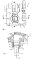
- the reference 1 designates as a whole a valve unit, shown only partially, arranged to be connected to a pipe 2, according to a system for leaktight connection provided according to the present invention.
- the pipe may form the supply pipe or delivery pipe for the gas relative to the valve unit. Provision may also be made for both the supply pipe and the delivery pipe for the gas to be arranged to be connected in a leaktight manner to the body 1a of the valve unit by means of the system of the invention. A description will therefore now be given of the connection system with reference only to the pipe 2, within the limits of the aforesaid explanation.
- Said tube is connected to the valve unit in the region of an attachment provided on the body 1a of the valve unit.
- Said attachment is of the threaded engagement type and comprises a male attachment element 3, formed integrally with the valve body 1a and projecting axially therefrom, as shown in the drawings.
- the threaded attachment element 3 is cylindrical in shape and has an axial cavity 4, in the form of a cylindrical through bore, intended to place the pipe 2 in flow communication with the gas through-flow inside the valve unit.
- the through cavity 4 is coaxial with the cylindrical threaded attachment 3, with X indicating the direction of their axial extension.
- the attachment element starting from the valve body 1a, comprises a first portion including a groove 5, extending for at least part of its circumferential profile, and a second cylindrical portion, in prolongation of the first portion, and on which the external thread of the attachment is provided. At the free end of the attachment an annular front surface 6 is defined.
- a further radial shoulder surface, indicated by 7, is provided inside the axial cavity 4 and is defined, in the direction of the free end of the attachment, between a first axial part of the cylindrical cavity 4 and a second axial part of the cavity, adjacent to the first part and having a larger diameter than said first part, as is clearly shown in Figures 4 and 5 .
- the pipe 2 comprises in its outer cylindrical surface, in the region of the end connectible to the valve unit, a shoulder surface 8.
- the radial shoulder is defined between a first axial pipe portion 2a, extending from the free end of the pipe itself, and a second axial portion 2b of the pipe, adjacent to the first portion and having a smaller diameter than the first portion.
- a circumferential seat 9 is also provided, intended to house a sealing ring 10, for example of the O-ring type, in order to ensure gas-tightness in contact with the inner surface of the axial cavity 4, following the connection by engagement of the pipe 2 in the cavity itself.
- connection system also comprises a retaining element, indicated as a whole by 11, which can be restrained axially, and releasably, on the valve body 1a, and can also itself retain the pipe 2, in a manner secured to the valve unit and gas-tight, as will become clear from the following description.
- a retaining element indicated as a whole by 11, which can be restrained axially, and releasably, on the valve body 1a, and can also itself retain the pipe 2, in a manner secured to the valve unit and gas-tight, as will become clear from the following description.
- the retaining element 11 is formed as a clip made of metal sheet, for example of harmonic steel, which has a preferred forked shape with two opposed arms 12, 13 connected to each other at one end by a linking portion 14.
- a pair of opposed branches 12a, 12b are defined, extending substantially parallel to each other and also spaced apart. They are also connected at their free ends, on the side remote from the linking portion 14, by a connecting crosspiece 15.
- a pair of branches 13a, 13b are defined, extending substantially parallel and spaced apart from each other.
- the reference 16 indicates a corresponding connecting crosspiece for the branches 13a, 13b.
- the arms 12, 13 are shaped as mirror-images of each other with respect to a central median plane of symmetry, passing perpendicularly to the upper flat linking portion 14 of the clip.
- a respective central portion 12c, 13c with curved profile is defined, the radius of curvature of which is selected such that the portions are in abutment against the shoulder 5 of the groove 5, as a result of the connection of the clip to the valve body.
- a respective central portion 12d, 13d with curved profile is defined, the radius of curvature of which is selected such that the portions are in abutment against the shoulder 8 of the pipe 2, as a result of the connection of the clip to the valve body.
- 16a are the respective through openings which are defined in the arms 12, 13, by the continuous peripheral profile delimited by the opposed branches and by the connecting portions of same.
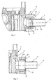
- connection system of the invention provides that, starting from the position of Figure 2 , with the parts disengaged, with mutual axial spacing, the pipe 2 is inserted with its portion 2a into the cylindrical axial cavity 4 of the valve body. The insertion is completed when the free end of the pipe is in abutment against the internal shoulder 7. In this position the sealing ring 10 is in contact with the cylindrical surface of the cylindrical cavity 4, ensuring, by means of appropriate choice of dimensions, the gas-tight seal between the coupled cylindrical surfaces.
- the clip element 11 in a movement transverse to the axis X, is fitted onto the attachment 3, with prior resilient opening out of the arms 12 and 13 (as a result of the interference encountered through the presence of the cylindrical threaded portion of the attachment itself).
- the movement transverse to the axis X is completed when the portions 12c, 13c of the clip are engaged in the groove 5, engaging in abutment against the shoulder 5a.
- the portions 12d, 13d are caused to engage the outer surface of the pipe by abutting against the shoulder 8.
- the presence of the openings 15a, 16a in the respective arms of the clip 11 allows it to be fitted onto the threaded portion of the attachment, without interfering with the attachment itself.
- the system lends itself advantageously to being employed in valve units provided with threaded male attachments, of the type described, the threads of which are intended to be engaged by pipe-fixing ring-nuts, whenever a conventional type of leaktight connection is opted for, which can be provided as an alternative to the connection system of the invention, the two systems being thus able to co-exist and be employed as an alternative to each other for the same valve unit, and in dependence on the different type of pipe selected for connection to the valve unit, all of which widens the possibilities of connection provided in the stage of constructional installation of the valve unit with the corresponding pipes.
- Figure 6 illustrates schematically a conventional type of connection in which the valve unit 1 described above is connected in a leaktight manner to a pipe 2' which has a frontal annular end edge 20 which can be surface connected, by superposition, to the front surface 6 of the attachment.
- a respective pipe-fixing ring-nut or nut 25 is provided, fitted onto the corresponding pipe and including an internally threaded cylindrical seat 25a, the nutscrew of which can be engaged by screwing on the corresponding threaded portion of the attachment 4.
- the screwing action effects the axial clamping between the surfaces 6 and 20 in mutual contact.
- An optional sealing ring 31 may be interposed between the aforesaid surfaces in order to ensure gas-tightness between the coupled parts.
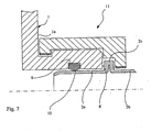
- FIG. 7 illustrates an alternative embodiment of the invention, in which details analogous to those of the example of Figure 5 are designated by the same reference numerals.
- This variant differs principally in that the sealing ring 10, of the O-ring type, is pre-mounted in the axial cavity 4 of the valve body 1a, for example housed in a suitable seat formed in the cylindrical wall of the cavity.
- Said pipe conveniently has a pinch 2c protruding circumferentially and which defines a circumferential raised portion which can abut between the front surface 6 of the attachment and the portions 12d, 13d of the clip, thus effecting the axial clamping of the pipe 2.
- the retaining element may assume a different shape from that previously described, but in any case such as to have at least a first and a second surface portion, spaced apart from each other axially and which can also abut against the shoulders 5a and 8 so as to secure and axially restrain the parts coupled to each other.
- the clip may be of a different material and shape, but still within the same inventive concept which is the basis of the system claimed.
- the invention thus achieves the aims proposed, obtaining the advantages mentioned above compared with the known solutions.
Landscapes
- Engineering & Computer Science (AREA)
- General Engineering & Computer Science (AREA)
- Mechanical Engineering (AREA)
- Valve Housings (AREA)
- Quick-Acting Or Multi-Walled Pipe Joints (AREA)
- Feeding And Controlling Fuel (AREA)
Claims (9)
- Système pour le raccordement étanche d'un ensemble de vanne (1) à un tuyau (2) respectif, en particulier pour des gaz combustibles, dans lequel l'ensemble de vanne comprend une section d'écoulement de gaz qui peut être raccordée, en communication d'écoulement, à une section d'extrémité respective du tuyau, un élément de fixation mâle fileté (3) étant formé de manière solidaire avec l'ensemble de vanne et ayant une cavité de passage axiale (4) définissant la section d'écoulement de gaz, l'élément de fixation (3) comprenant, au niveau de son extrémité libre, une surface annulaire pouvant être raccordée à un premier type respectif d'extrémité de tuyau (2), le serrage avec l'étanchéité au gaz facultative entre les surfaces de couplage pouvant être obtenu par des moyens d'écrou à oeillet de fixation de tuyau qui peuvent être vissés sur la partie filetée mâle de l'élément de fixation, caractérisé en ce que le système comprend des deuxièmes moyens de raccordement étanches qui peuvent être mis en oeuvre à titre de variante aux moyens de raccordement par écrou à oeillet qui peuvent être vissés sur l'élément de fixation mâle, pour le raccordement de l'ensemble de vanne à au moins un second type d'extrémité de tuyau, les seconds moyens de raccordement comprenant :au moins une première surface d'épaulement (5a) qui est prévue dans la région de l'extrémité axiale de l'élément de fixation mâle (3) qui s'étend à l'extrémité longitudinalement à distance de son extrémité libre,au moins une deuxième surface d'épaulement (8) prévue sur la surface externe du tuyau (2), le second épaulement étant défini entre une première partie (2a) du tuyau qui peut être mise en prise dans la cavité centrale de la fixation mâle et une seconde partie (2b) qui fait saillie hors de la cavité lorsque le tuyau y est logé,au moins une troisième surface d'épaulement (7) qui est formée dans la surface interne de la cavité (4) s'étendant axialement à travers l'élément de fixation mâle (3) et laquelle extrémité libre du tuyau (2) peut venir en butée lorsque le tuyau est logé dans la cavité (4), dans une position de mise en prise opérationnelle correspondante,au moins un élément de retenue axial (11) qui peut être retenu de manière amovible sur l'ensemble de vanne (1) dans la région de la partie filetée de l'élément de fixation mâle (3), l'élément de retenue comprenant au moins une première partie de surface et une deuxième partie de surface qui sont espacées axialement et peuvent venir en butée contre les première et deuxième surfaces d'épaulement (5a, 8) respectivement, dans la position opérationnelle du tuyau, en raison du couplage de l'élément de retenue avec l'ensemble de vanne de sorte que l'on empêche le tuyau (2) de sortir axialement de la position opérationnelle par rapport à l'ensemble de vanne,des moyens étanches au gaz étant prévus entre la surface externe de la première partie (2a) du tuyau et la surface de la cavité (4) qui s'étend à travers l'élément de fixation (3) et peut loger le tuyau.
- Système de raccordement selon la revendication 1, dans lequel la première surface d'épaulement (5a) est définie dans une rainure (5) s'étendant autour d'au moins une partie circonférentielle de la surface externe de l'élément de fixation mâle (3) dans une position entre le corps (1a) de l'ensemble de vanne et la partie filetée de l'élément (3).
- Système de raccordement selon la revendication 2, dans lequel l'élément de retenue (11) est formé comme un collier de serrage élastique, la première partie de surface comprenant une première paire de branches (12c, 13c) du collier de serrage qui peuvent mettre en prise la rainure (5) sur ses côtés diamétralement opposés, la seconde partie de surface comprenant une seconde paire de branches (12d, 13d) du collier de serrage qui peuvent venir en butée contre la deuxième surface d'épaulement (8) sur les côtés diamétralement opposés de la surface externe du tuyau.
- Système de raccordement selon la revendication 3, dans lequel la première paire de branches du collier de serrage est raccordée à la deuxième paire de branches par au moins une partie de liaison (14) qui s'étend axialement lorsque le collier de serrage est monté dans la position opérationnelle sur l'ensemble de vanne mais qui a une taille afin de s'étendre autour de la partie filetée de l'élément de fixation mâle (3) sans interférence.
- Système de raccordement selon la revendication 4, dans lequel chaque branche (12c, 13c) de la première paire et chaque branche (12d, 13d) correspondante de la deuxième paire qui est positionnée du même côté de l'élément de fixation (3) sont axialement espacées, l'espacement étant sélectionné de sorte que, lorsque le collier de serrage est monté sur l'ensemble de vanne, les branches n'interfèrent pas avec la partie filetée de l'élément de fixation étant donné qu'elles sont positionnées au niveau de ses extrémités axiales opposées, sans interférence.
- Système de raccordement selon la revendication 5, dans lequel chaque branche de la première paire est raccordée à la branche correspondante de la deuxième paire qui est disposée du même côté de l'élément de fixation par la partie de raccordement qui s'étend entre les extrémités des branches à distance des extrémités qui sont positionnées dans la région de la partie de liaison (14).
- Système de raccordement selon l'une quelconque des revendications 3 à 6, dans lequel les branches de chaque paire ont une forme avec un profil principalement incurvé correspondant au profil de la surface externe de l'élément de fixation mâle (3), avec des rayons de courbure afin de se mettre en prise en butée avec les première et deuxième surfaces d'épaulement (5a, 8) respectivement.
- Système de raccordement selon l'une quelconque des revendications 3 à 7, dans lequel le collier de serrage est mobile à distance et vers la position opérationnelle transversalement par rapport à l'axe principal de l'élément de fixation mâle (3), les branches de chacune des première et seconde paires pouvant être ouvertes de manière élastique, radialement à distance et vers la position opérationnelle dans laquelle le tuyau (2) est bloqué axialement par rapport à l'ensemble de vanne (1).
- Système de raccordement selon la revendication 1, dans lequel les moyens étanches au gaz comprennent au moins une bague d'étanchéité (10) qui est logée dans un siège circonférentiel (9) de la première partie de tuyau (2) et qui peut entrer en contact avec la surface interne cylindrique de la cavité centrale (4) prévue dans l'élément de fixation (3) pour la mise en prise du tuyau, ce contact garantissant l'étanchéité au gaz entre les surfaces qui sont mutuellement mises en prise dans la mise en prise du tuyau (2) avec l'ensemble de vanne (1).
Applications Claiming Priority (2)
| Application Number | Priority Date | Filing Date | Title |
|---|---|---|---|
| ITPD2008A000201A IT1390600B1 (it) | 2008-07-08 | 2008-07-08 | Sistema di connessione a tenuta di gruppi valvolari con rispettive tubazioni, in particolare nell'impiego con gas combustibili |
| PCT/IT2009/000295 WO2010004604A1 (fr) | 2008-07-08 | 2009-07-03 | Système de raccordement étanche d’ensembles vanne à leur conduit respectif, en particulier destiné à être utilisé avec des gaz combustibles |
Publications (2)
| Publication Number | Publication Date |
|---|---|
| EP2307782A1 EP2307782A1 (fr) | 2011-04-13 |
| EP2307782B1 true EP2307782B1 (fr) | 2012-08-15 |
Family
ID=41319395
Family Applications (1)
| Application Number | Title | Priority Date | Filing Date |
|---|---|---|---|
| EP09787771A Not-in-force EP2307782B1 (fr) | 2008-07-08 | 2009-07-03 | Système de raccordement étanche d ensembles vanne à leur conduit respectif, en particulier destiné à être utilisé avec des gaz combustibles |
Country Status (4)
| Country | Link |
|---|---|
| US (1) | US20110101674A1 (fr) |
| EP (1) | EP2307782B1 (fr) |
| IT (1) | IT1390600B1 (fr) |
| WO (1) | WO2010004604A1 (fr) |
Families Citing this family (11)
| Publication number | Priority date | Publication date | Assignee | Title |
|---|---|---|---|---|
| US9797535B2 (en) | 2013-04-16 | 2017-10-24 | Eaton Corporation | Bonding clip for fluid conduit coupling |
| ES2570230B1 (es) * | 2014-11-14 | 2017-02-27 | Bsh Electrodomésticos España, S.A. | Dispositivo de unión y campo de cocción a gas |
| US9951821B1 (en) | 2017-01-11 | 2018-04-24 | Crossford International, Llc | Drive shaft coupling |
| CN108105493A (zh) * | 2018-02-08 | 2018-06-01 | 江阴市亚龙换热设备有限公司 | 两段式接头管件 |
| WO2019218716A1 (fr) * | 2018-05-15 | 2019-11-21 | 芜湖美的厨卫电器制造有限公司 | Structure de raccordement de tuyau d'eau et brûleur |
| KR102798626B1 (ko) | 2020-10-26 | 2025-04-23 | 외티커 엔와이, 인크. | 유체 연결 조립체 |
| US12110999B2 (en) | 2020-10-26 | 2024-10-08 | Oetiker Ny, Inc. | Fluid connection assembly |
| WO2022093166A1 (fr) | 2020-10-26 | 2022-05-05 | Oetiker Ny, Inc. | Ensemble de raccordement de fluide |
| JP2023547911A (ja) | 2020-10-26 | 2023-11-14 | オエティカ エヌワイ インク | 流体接続アセンブリ |
| US12410876B2 (en) | 2021-06-02 | 2025-09-09 | Oetiker Ny, Inc. | Fluid connection assembly |
| KR20240151853A (ko) | 2022-04-05 | 2024-10-18 | 외티커 엔와이, 인크. | 유체 연결 조립체 |
Family Cites Families (5)
| Publication number | Priority date | Publication date | Assignee | Title |
|---|---|---|---|---|
| US3479069A (en) * | 1967-10-20 | 1969-11-18 | Amseco Corp | Connector assembly |
| US3881753A (en) * | 1973-06-04 | 1975-05-06 | Michael E Bochory | Fastener mechanism |
| DE3739626C2 (de) * | 1987-11-23 | 1996-03-07 | Schaefer Stettiner Schrauben | Steckverbindung |
| SE466813B (sv) * | 1990-02-15 | 1992-04-06 | Gambro Dialysatoren | Anvaendning av en nippel, som aer avsedd att bilda en del av en s k hansen-koppling |
| JP2006226421A (ja) * | 2005-02-18 | 2006-08-31 | Tokai Rubber Ind Ltd | コネクタ取り付け構造 |
-
2008
- 2008-07-08 IT ITPD2008A000201A patent/IT1390600B1/it active
-
2009
- 2009-07-03 EP EP09787771A patent/EP2307782B1/fr not_active Not-in-force
- 2009-07-03 US US13/001,544 patent/US20110101674A1/en not_active Abandoned
- 2009-07-03 WO PCT/IT2009/000295 patent/WO2010004604A1/fr not_active Ceased
Also Published As
| Publication number | Publication date |
|---|---|
| EP2307782A1 (fr) | 2011-04-13 |
| IT1390600B1 (it) | 2011-09-09 |
| US20110101674A1 (en) | 2011-05-05 |
| WO2010004604A1 (fr) | 2010-01-14 |
| ITPD20080201A1 (it) | 2010-01-09 |
Similar Documents
| Publication | Publication Date | Title |
|---|---|---|
| US20110101674A1 (en) | System for the leaktight connection of valve units to respective pipes, in particular for use with combustible gases | |
| US8474878B2 (en) | Securing device of a fluid line connection | |
| US4693502A (en) | Pipe connection | |
| EP0444857B1 (fr) | Arrangement de raccord | |
| US7270349B2 (en) | Quick-release coupling for pipes | |
| JP5301789B2 (ja) | ハイブリッド急速継手 | |
| JP4932844B2 (ja) | 角度をなすように配向された空洞を有する管継手セグメント | |
| EP1653144B1 (fr) | Raccord pour fluide à enclenchement rapide | |
| US7726702B2 (en) | Flange connection for pipe | |
| JPH11500519A (ja) | チューブを継手に連結する装置 | |
| US5489125A (en) | Quick connect coupling for connecting two fluid conduits | |
| CN101095005A (zh) | 具有截止阀接口的出墙残管流体快速连接器 | |
| US20100259039A1 (en) | Press fitting for a pipe, in particular plastic pipe or plastic and metal composite pipe | |
| EP3237804B1 (fr) | Assemblage de combustion avec un système d'alimentation en carburant à accouplement d'alimentation en carburant à encliquetage rapide pour chambre de combustion à turbine à gaz | |
| EP3201509B1 (fr) | Raccord pour tuyaux | |
| AU756297B2 (en) | Plug-in coupling | |
| CN108071886B (zh) | 用于介质传导管线的联接装置 | |
| EP1543266B1 (fr) | Raccord rapide a fluide pour composants filetes a fluide | |
| EP0995937A2 (fr) | Dispositif d'accouplement pour fluides avec filetages échelonnés et synchronisés | |
| GB2463896A (en) | Plug-in pipe coupling | |
| US20040245773A1 (en) | Plug-in connection device, especially for fluid lines | |
| US10046258B2 (en) | Device for locking a filter in a conduit | |
| WO2007101456A1 (fr) | Vanne, pour gaz en particulier | |
| CN101238317A (zh) | 用于流体管道装置的联结器 | |
| KR200495710Y1 (ko) | 파이프 조인트 |
Legal Events
| Date | Code | Title | Description |
|---|---|---|---|
| PUAI | Public reference made under article 153(3) epc to a published international application that has entered the european phase |
Free format text: ORIGINAL CODE: 0009012 |
|
| 17P | Request for examination filed |
Effective date: 20101223 |
|
| AK | Designated contracting states |
Kind code of ref document: A1 Designated state(s): AT BE BG CH CY CZ DE DK EE ES FI FR GB GR HR HU IE IS IT LI LT LU LV MC MK MT NL NO PL PT RO SE SI SK SM TR |
|
| AX | Request for extension of the european patent |
Extension state: AL BA RS |
|
| DAX | Request for extension of the european patent (deleted) | ||
| GRAP | Despatch of communication of intention to grant a patent |
Free format text: ORIGINAL CODE: EPIDOSNIGR1 |
|
| RIN1 | Information on inventor provided before grant (corrected) |
Inventor name: DE IULIO, DAVIDE Inventor name: ZANELLA, STEFANO Inventor name: BUCCI, MARCO Inventor name: BENVENUTO, MICHELE Inventor name: PERON, LUCA |
|
| GRAS | Grant fee paid |
Free format text: ORIGINAL CODE: EPIDOSNIGR3 |
|
| GRAA | (expected) grant |
Free format text: ORIGINAL CODE: 0009210 |
|
| AK | Designated contracting states |
Kind code of ref document: B1 Designated state(s): AT BE BG CH CY CZ DE DK EE ES FI FR GB GR HR HU IE IS IT LI LT LU LV MC MK MT NL NO PL PT RO SE SI SK SM TR |
|
| REG | Reference to a national code |
Ref country code: AT Ref legal event code: REF Ref document number: 571041 Country of ref document: AT Kind code of ref document: T Effective date: 20120815 Ref country code: GB Ref legal event code: FG4D Ref country code: CH Ref legal event code: EP |
|
| REG | Reference to a national code |
Ref country code: IE Ref legal event code: FG4D |
|
| REG | Reference to a national code |
Ref country code: DE Ref legal event code: R096 Ref document number: 602009009093 Country of ref document: DE Effective date: 20121011 |
|
| REG | Reference to a national code |
Ref country code: NL Ref legal event code: T3 |
|
| REG | Reference to a national code |
Ref country code: AT Ref legal event code: MK05 Ref document number: 571041 Country of ref document: AT Kind code of ref document: T Effective date: 20120815 |
|
| PG25 | Lapsed in a contracting state [announced via postgrant information from national office to epo] |
Ref country code: HR Free format text: LAPSE BECAUSE OF FAILURE TO SUBMIT A TRANSLATION OF THE DESCRIPTION OR TO PAY THE FEE WITHIN THE PRESCRIBED TIME-LIMIT Effective date: 20120815 Ref country code: IS Free format text: LAPSE BECAUSE OF FAILURE TO SUBMIT A TRANSLATION OF THE DESCRIPTION OR TO PAY THE FEE WITHIN THE PRESCRIBED TIME-LIMIT Effective date: 20121215 Ref country code: FI Free format text: LAPSE BECAUSE OF FAILURE TO SUBMIT A TRANSLATION OF THE DESCRIPTION OR TO PAY THE FEE WITHIN THE PRESCRIBED TIME-LIMIT Effective date: 20120815 Ref country code: AT Free format text: LAPSE BECAUSE OF FAILURE TO SUBMIT A TRANSLATION OF THE DESCRIPTION OR TO PAY THE FEE WITHIN THE PRESCRIBED TIME-LIMIT Effective date: 20120815 Ref country code: NO Free format text: LAPSE BECAUSE OF FAILURE TO SUBMIT A TRANSLATION OF THE DESCRIPTION OR TO PAY THE FEE WITHIN THE PRESCRIBED TIME-LIMIT Effective date: 20121115 Ref country code: LT Free format text: LAPSE BECAUSE OF FAILURE TO SUBMIT A TRANSLATION OF THE DESCRIPTION OR TO PAY THE FEE WITHIN THE PRESCRIBED TIME-LIMIT Effective date: 20120815 |
|
| PG25 | Lapsed in a contracting state [announced via postgrant information from national office to epo] |
Ref country code: PT Free format text: LAPSE BECAUSE OF FAILURE TO SUBMIT A TRANSLATION OF THE DESCRIPTION OR TO PAY THE FEE WITHIN THE PRESCRIBED TIME-LIMIT Effective date: 20121217 Ref country code: BE Free format text: LAPSE BECAUSE OF FAILURE TO SUBMIT A TRANSLATION OF THE DESCRIPTION OR TO PAY THE FEE WITHIN THE PRESCRIBED TIME-LIMIT Effective date: 20120815 Ref country code: GR Free format text: LAPSE BECAUSE OF FAILURE TO SUBMIT A TRANSLATION OF THE DESCRIPTION OR TO PAY THE FEE WITHIN THE PRESCRIBED TIME-LIMIT Effective date: 20121116 Ref country code: SE Free format text: LAPSE BECAUSE OF FAILURE TO SUBMIT A TRANSLATION OF THE DESCRIPTION OR TO PAY THE FEE WITHIN THE PRESCRIBED TIME-LIMIT Effective date: 20120815 Ref country code: PL Free format text: LAPSE BECAUSE OF FAILURE TO SUBMIT A TRANSLATION OF THE DESCRIPTION OR TO PAY THE FEE WITHIN THE PRESCRIBED TIME-LIMIT Effective date: 20120815 Ref country code: LV Free format text: LAPSE BECAUSE OF FAILURE TO SUBMIT A TRANSLATION OF THE DESCRIPTION OR TO PAY THE FEE WITHIN THE PRESCRIBED TIME-LIMIT Effective date: 20120815 Ref country code: SI Free format text: LAPSE BECAUSE OF FAILURE TO SUBMIT A TRANSLATION OF THE DESCRIPTION OR TO PAY THE FEE WITHIN THE PRESCRIBED TIME-LIMIT Effective date: 20120815 |
|
| PG25 | Lapsed in a contracting state [announced via postgrant information from national office to epo] |
Ref country code: CZ Free format text: LAPSE BECAUSE OF FAILURE TO SUBMIT A TRANSLATION OF THE DESCRIPTION OR TO PAY THE FEE WITHIN THE PRESCRIBED TIME-LIMIT Effective date: 20120815 Ref country code: DK Free format text: LAPSE BECAUSE OF FAILURE TO SUBMIT A TRANSLATION OF THE DESCRIPTION OR TO PAY THE FEE WITHIN THE PRESCRIBED TIME-LIMIT Effective date: 20120815 Ref country code: RO Free format text: LAPSE BECAUSE OF FAILURE TO SUBMIT A TRANSLATION OF THE DESCRIPTION OR TO PAY THE FEE WITHIN THE PRESCRIBED TIME-LIMIT Effective date: 20120815 Ref country code: EE Free format text: LAPSE BECAUSE OF FAILURE TO SUBMIT A TRANSLATION OF THE DESCRIPTION OR TO PAY THE FEE WITHIN THE PRESCRIBED TIME-LIMIT Effective date: 20120815 Ref country code: ES Free format text: LAPSE BECAUSE OF FAILURE TO SUBMIT A TRANSLATION OF THE DESCRIPTION OR TO PAY THE FEE WITHIN THE PRESCRIBED TIME-LIMIT Effective date: 20121126 |
|
| PG25 | Lapsed in a contracting state [announced via postgrant information from national office to epo] |
Ref country code: SK Free format text: LAPSE BECAUSE OF FAILURE TO SUBMIT A TRANSLATION OF THE DESCRIPTION OR TO PAY THE FEE WITHIN THE PRESCRIBED TIME-LIMIT Effective date: 20120815 |
|
| PLBE | No opposition filed within time limit |
Free format text: ORIGINAL CODE: 0009261 |
|
| STAA | Information on the status of an ep patent application or granted ep patent |
Free format text: STATUS: NO OPPOSITION FILED WITHIN TIME LIMIT |
|
| 26N | No opposition filed |
Effective date: 20130516 |
|
| PG25 | Lapsed in a contracting state [announced via postgrant information from national office to epo] |
Ref country code: BG Free format text: LAPSE BECAUSE OF FAILURE TO SUBMIT A TRANSLATION OF THE DESCRIPTION OR TO PAY THE FEE WITHIN THE PRESCRIBED TIME-LIMIT Effective date: 20121115 |
|
| REG | Reference to a national code |
Ref country code: DE Ref legal event code: R097 Ref document number: 602009009093 Country of ref document: DE Effective date: 20130516 |
|
| PG25 | Lapsed in a contracting state [announced via postgrant information from national office to epo] |
Ref country code: CY Free format text: LAPSE BECAUSE OF FAILURE TO SUBMIT A TRANSLATION OF THE DESCRIPTION OR TO PAY THE FEE WITHIN THE PRESCRIBED TIME-LIMIT Effective date: 20120815 |
|
| PG25 | Lapsed in a contracting state [announced via postgrant information from national office to epo] |
Ref country code: MC Free format text: LAPSE BECAUSE OF FAILURE TO SUBMIT A TRANSLATION OF THE DESCRIPTION OR TO PAY THE FEE WITHIN THE PRESCRIBED TIME-LIMIT Effective date: 20120815 |
|
| REG | Reference to a national code |
Ref country code: CH Ref legal event code: PL |
|
| REG | Reference to a national code |
Ref country code: IE Ref legal event code: MM4A |
|
| PG25 | Lapsed in a contracting state [announced via postgrant information from national office to epo] |
Ref country code: CH Free format text: LAPSE BECAUSE OF NON-PAYMENT OF DUE FEES Effective date: 20130731 Ref country code: LI Free format text: LAPSE BECAUSE OF NON-PAYMENT OF DUE FEES Effective date: 20130731 |
|
| PG25 | Lapsed in a contracting state [announced via postgrant information from national office to epo] |
Ref country code: IE Free format text: LAPSE BECAUSE OF NON-PAYMENT OF DUE FEES Effective date: 20130703 |
|
| PGFP | Annual fee paid to national office [announced via postgrant information from national office to epo] |
Ref country code: IT Payment date: 20140618 Year of fee payment: 6 |
|
| PGFP | Annual fee paid to national office [announced via postgrant information from national office to epo] |
Ref country code: DE Payment date: 20140721 Year of fee payment: 6 Ref country code: NL Payment date: 20140721 Year of fee payment: 6 |
|
| PGFP | Annual fee paid to national office [announced via postgrant information from national office to epo] |
Ref country code: GB Payment date: 20140721 Year of fee payment: 6 Ref country code: FR Payment date: 20140721 Year of fee payment: 6 |
|
| REG | Reference to a national code |
Ref country code: DE Ref legal event code: R082 Ref document number: 602009009093 Country of ref document: DE Representative=s name: DREISS PATENTANWAELTE PARTG MBB, DE |
|
| REG | Reference to a national code |
Ref country code: GB Ref legal event code: 732E Free format text: REGISTERED BETWEEN 20150122 AND 20150128 |
|
| REG | Reference to a national code |
Ref country code: DE Ref legal event code: R082 Ref document number: 602009009093 Country of ref document: DE Representative=s name: DREISS PATENTANWAELTE PARTG MBB, DE Effective date: 20150213 Ref country code: DE Ref legal event code: R081 Ref document number: 602009009093 Country of ref document: DE Owner name: SIT S.P.A., IT Free format text: FORMER OWNER: SIT LA PRECISA S.P.A., PADOVA, IT Effective date: 20150213 |
|
| REG | Reference to a national code |
Ref country code: FR Ref legal event code: TP Owner name: SIT S.P.A., IT Effective date: 20150223 |
|
| PG25 | Lapsed in a contracting state [announced via postgrant information from national office to epo] |
Ref country code: SM Free format text: LAPSE BECAUSE OF FAILURE TO SUBMIT A TRANSLATION OF THE DESCRIPTION OR TO PAY THE FEE WITHIN THE PRESCRIBED TIME-LIMIT Effective date: 20120815 |
|
| REG | Reference to a national code |
Ref country code: NL Ref legal event code: SD Effective date: 20150602 |
|
| PG25 | Lapsed in a contracting state [announced via postgrant information from national office to epo] |
Ref country code: MT Free format text: LAPSE BECAUSE OF FAILURE TO SUBMIT A TRANSLATION OF THE DESCRIPTION OR TO PAY THE FEE WITHIN THE PRESCRIBED TIME-LIMIT Effective date: 20120815 Ref country code: TR Free format text: LAPSE BECAUSE OF FAILURE TO SUBMIT A TRANSLATION OF THE DESCRIPTION OR TO PAY THE FEE WITHIN THE PRESCRIBED TIME-LIMIT Effective date: 20120815 |
|
| PG25 | Lapsed in a contracting state [announced via postgrant information from national office to epo] |
Ref country code: LU Free format text: LAPSE BECAUSE OF NON-PAYMENT OF DUE FEES Effective date: 20130703 Ref country code: MK Free format text: LAPSE BECAUSE OF FAILURE TO SUBMIT A TRANSLATION OF THE DESCRIPTION OR TO PAY THE FEE WITHIN THE PRESCRIBED TIME-LIMIT Effective date: 20120815 Ref country code: HU Free format text: LAPSE BECAUSE OF FAILURE TO SUBMIT A TRANSLATION OF THE DESCRIPTION OR TO PAY THE FEE WITHIN THE PRESCRIBED TIME-LIMIT; INVALID AB INITIO Effective date: 20090703 |
|
| REG | Reference to a national code |
Ref country code: DE Ref legal event code: R119 Ref document number: 602009009093 Country of ref document: DE |
|
| GBPC | Gb: european patent ceased through non-payment of renewal fee |
Effective date: 20150703 |
|
| REG | Reference to a national code |
Ref country code: NL Ref legal event code: MM Effective date: 20150801 |
|
| PG25 | Lapsed in a contracting state [announced via postgrant information from national office to epo] |
Ref country code: IT Free format text: LAPSE BECAUSE OF NON-PAYMENT OF DUE FEES Effective date: 20150703 Ref country code: GB Free format text: LAPSE BECAUSE OF NON-PAYMENT OF DUE FEES Effective date: 20150703 Ref country code: DE Free format text: LAPSE BECAUSE OF NON-PAYMENT OF DUE FEES Effective date: 20160202 |
|
| REG | Reference to a national code |
Ref country code: FR Ref legal event code: ST Effective date: 20160331 |
|
| PG25 | Lapsed in a contracting state [announced via postgrant information from national office to epo] |
Ref country code: NL Free format text: LAPSE BECAUSE OF NON-PAYMENT OF DUE FEES Effective date: 20150801 Ref country code: FR Free format text: LAPSE BECAUSE OF NON-PAYMENT OF DUE FEES Effective date: 20150731 |