EP2307789B1 - Dispositif d'éclairage avec del - Google Patents
Dispositif d'éclairage avec del Download PDFInfo
- Publication number
- EP2307789B1 EP2307789B1 EP09775575.5A EP09775575A EP2307789B1 EP 2307789 B1 EP2307789 B1 EP 2307789B1 EP 09775575 A EP09775575 A EP 09775575A EP 2307789 B1 EP2307789 B1 EP 2307789B1
- Authority
- EP
- European Patent Office
- Prior art keywords
- light
- carrier element
- lighting device
- led
- carrier
- Prior art date
- Legal status (The legal status is an assumption and is not a legal conclusion. Google has not performed a legal analysis and makes no representation as to the accuracy of the status listed.)
- Not-in-force
Links
- 238000001816 cooling Methods 0.000 claims description 4
- 239000004020 conductor Substances 0.000 claims description 3
- 238000005286 illumination Methods 0.000 description 12
- 238000009423 ventilation Methods 0.000 description 7
- 239000000919 ceramic Substances 0.000 description 6
- 230000005855 radiation Effects 0.000 description 6
- 239000000758 substrate Substances 0.000 description 6
- 238000005516 engineering process Methods 0.000 description 5
- 239000004065 semiconductor Substances 0.000 description 5
- 150000001875 compounds Chemical class 0.000 description 4
- 239000000463 material Substances 0.000 description 4
- 238000004382 potting Methods 0.000 description 4
- 238000013461 design Methods 0.000 description 3
- 230000000694 effects Effects 0.000 description 3
- 230000017525 heat dissipation Effects 0.000 description 3
- 239000011159 matrix material Substances 0.000 description 3
- 238000006243 chemical reaction Methods 0.000 description 2
- 239000003086 colorant Substances 0.000 description 2
- 238000004891 communication Methods 0.000 description 2
- 238000012423 maintenance Methods 0.000 description 2
- 239000002184 metal Substances 0.000 description 2
- 230000003287 optical effect Effects 0.000 description 2
- 229920003002 synthetic resin Polymers 0.000 description 2
- 239000000057 synthetic resin Substances 0.000 description 2
- 102100037149 3-oxoacyl-[acyl-carrier-protein] synthase, mitochondrial Human genes 0.000 description 1
- 101001098439 Homo sapiens 3-oxoacyl-[acyl-carrier-protein] synthase, mitochondrial Proteins 0.000 description 1
- XUIMIQQOPSSXEZ-UHFFFAOYSA-N Silicon Chemical compound [Si] XUIMIQQOPSSXEZ-UHFFFAOYSA-N 0.000 description 1
- 239000002390 adhesive tape Substances 0.000 description 1
- 230000032683 aging Effects 0.000 description 1
- 230000015572 biosynthetic process Effects 0.000 description 1
- 239000003990 capacitor Substances 0.000 description 1
- 239000000969 carrier Substances 0.000 description 1
- 239000003795 chemical substances by application Substances 0.000 description 1
- 238000010276 construction Methods 0.000 description 1
- 230000008878 coupling Effects 0.000 description 1
- 238000010168 coupling process Methods 0.000 description 1
- 238000005859 coupling reaction Methods 0.000 description 1
- 238000011161 development Methods 0.000 description 1
- 230000018109 developmental process Effects 0.000 description 1
- 239000011521 glass Substances 0.000 description 1
- 229910052736 halogen Inorganic materials 0.000 description 1
- 150000002367 halogens Chemical class 0.000 description 1
- 230000010354 integration Effects 0.000 description 1
- 239000007769 metal material Substances 0.000 description 1
- 238000012544 monitoring process Methods 0.000 description 1
- 230000001105 regulatory effect Effects 0.000 description 1
- 238000009877 rendering Methods 0.000 description 1
- 229910052710 silicon Inorganic materials 0.000 description 1
- 239000010703 silicon Substances 0.000 description 1
- 239000000126 substance Substances 0.000 description 1
- 238000004383 yellowing Methods 0.000 description 1
Images


Classifications
-
- F—MECHANICAL ENGINEERING; LIGHTING; HEATING; WEAPONS; BLASTING
- F21—LIGHTING
- F21K—NON-ELECTRIC LIGHT SOURCES USING LUMINESCENCE; LIGHT SOURCES USING ELECTROCHEMILUMINESCENCE; LIGHT SOURCES USING CHARGES OF COMBUSTIBLE MATERIAL; LIGHT SOURCES USING SEMICONDUCTOR DEVICES AS LIGHT-GENERATING ELEMENTS; LIGHT SOURCES NOT OTHERWISE PROVIDED FOR
- F21K9/00—Light sources using semiconductor devices as light-generating elements, e.g. using light-emitting diodes [LED] or lasers
-
- F—MECHANICAL ENGINEERING; LIGHTING; HEATING; WEAPONS; BLASTING
- F21—LIGHTING
- F21S—NON-PORTABLE LIGHTING DEVICES; SYSTEMS THEREOF; VEHICLE LIGHTING DEVICES SPECIALLY ADAPTED FOR VEHICLE EXTERIORS
- F21S8/00—Lighting devices intended for fixed installation
- F21S8/02—Lighting devices intended for fixed installation of recess-mounted type, e.g. downlighters
- F21S8/026—Lighting devices intended for fixed installation of recess-mounted type, e.g. downlighters intended to be recessed in a ceiling or like overhead structure, e.g. suspended ceiling
-
- F—MECHANICAL ENGINEERING; LIGHTING; HEATING; WEAPONS; BLASTING
- F21—LIGHTING
- F21S—NON-PORTABLE LIGHTING DEVICES; SYSTEMS THEREOF; VEHICLE LIGHTING DEVICES SPECIALLY ADAPTED FOR VEHICLE EXTERIORS
- F21S8/00—Lighting devices intended for fixed installation
- F21S8/04—Lighting devices intended for fixed installation intended only for mounting on a ceiling or the like overhead structures
-
- F—MECHANICAL ENGINEERING; LIGHTING; HEATING; WEAPONS; BLASTING
- F21—LIGHTING
- F21V—FUNCTIONAL FEATURES OR DETAILS OF LIGHTING DEVICES OR SYSTEMS THEREOF; STRUCTURAL COMBINATIONS OF LIGHTING DEVICES WITH OTHER ARTICLES, NOT OTHERWISE PROVIDED FOR
- F21V29/00—Protecting lighting devices from thermal damage; Cooling or heating arrangements specially adapted for lighting devices or systems
- F21V29/50—Cooling arrangements
- F21V29/502—Cooling arrangements characterised by the adaptation for cooling of specific components
- F21V29/505—Cooling arrangements characterised by the adaptation for cooling of specific components of reflectors
-
- F—MECHANICAL ENGINEERING; LIGHTING; HEATING; WEAPONS; BLASTING
- F21—LIGHTING
- F21V—FUNCTIONAL FEATURES OR DETAILS OF LIGHTING DEVICES OR SYSTEMS THEREOF; STRUCTURAL COMBINATIONS OF LIGHTING DEVICES WITH OTHER ARTICLES, NOT OTHERWISE PROVIDED FOR
- F21V29/00—Protecting lighting devices from thermal damage; Cooling or heating arrangements specially adapted for lighting devices or systems
- F21V29/50—Cooling arrangements
- F21V29/70—Cooling arrangements characterised by passive heat-dissipating elements, e.g. heat-sinks
- F21V29/74—Cooling arrangements characterised by passive heat-dissipating elements, e.g. heat-sinks with fins or blades
- F21V29/75—Cooling arrangements characterised by passive heat-dissipating elements, e.g. heat-sinks with fins or blades with fins or blades having different shapes, thicknesses or spacing
-
- F—MECHANICAL ENGINEERING; LIGHTING; HEATING; WEAPONS; BLASTING
- F21—LIGHTING
- F21S—NON-PORTABLE LIGHTING DEVICES; SYSTEMS THEREOF; VEHICLE LIGHTING DEVICES SPECIALLY ADAPTED FOR VEHICLE EXTERIORS
- F21S9/00—Lighting devices with a built-in power supply; Systems employing lighting devices with a built-in power supply
- F21S9/02—Lighting devices with a built-in power supply; Systems employing lighting devices with a built-in power supply the power supply being a battery or accumulator
- F21S9/022—Emergency lighting devices
-
- F—MECHANICAL ENGINEERING; LIGHTING; HEATING; WEAPONS; BLASTING
- F21—LIGHTING
- F21V—FUNCTIONAL FEATURES OR DETAILS OF LIGHTING DEVICES OR SYSTEMS THEREOF; STRUCTURAL COMBINATIONS OF LIGHTING DEVICES WITH OTHER ARTICLES, NOT OTHERWISE PROVIDED FOR
- F21V17/00—Fastening of component parts of lighting devices, e.g. shades, globes, refractors, reflectors, filters, screens, grids or protective cages
- F21V17/10—Fastening of component parts of lighting devices, e.g. shades, globes, refractors, reflectors, filters, screens, grids or protective cages characterised by specific fastening means or way of fastening
- F21V17/107—Fastening of component parts of lighting devices, e.g. shades, globes, refractors, reflectors, filters, screens, grids or protective cages characterised by specific fastening means or way of fastening using hinge joints
-
- F—MECHANICAL ENGINEERING; LIGHTING; HEATING; WEAPONS; BLASTING
- F21—LIGHTING
- F21V—FUNCTIONAL FEATURES OR DETAILS OF LIGHTING DEVICES OR SYSTEMS THEREOF; STRUCTURAL COMBINATIONS OF LIGHTING DEVICES WITH OTHER ARTICLES, NOT OTHERWISE PROVIDED FOR
- F21V17/00—Fastening of component parts of lighting devices, e.g. shades, globes, refractors, reflectors, filters, screens, grids or protective cages
- F21V17/10—Fastening of component parts of lighting devices, e.g. shades, globes, refractors, reflectors, filters, screens, grids or protective cages characterised by specific fastening means or way of fastening
- F21V17/14—Bayonet-type fastening
-
- F—MECHANICAL ENGINEERING; LIGHTING; HEATING; WEAPONS; BLASTING
- F21—LIGHTING
- F21V—FUNCTIONAL FEATURES OR DETAILS OF LIGHTING DEVICES OR SYSTEMS THEREOF; STRUCTURAL COMBINATIONS OF LIGHTING DEVICES WITH OTHER ARTICLES, NOT OTHERWISE PROVIDED FOR
- F21V17/00—Fastening of component parts of lighting devices, e.g. shades, globes, refractors, reflectors, filters, screens, grids or protective cages
- F21V17/10—Fastening of component parts of lighting devices, e.g. shades, globes, refractors, reflectors, filters, screens, grids or protective cages characterised by specific fastening means or way of fastening
- F21V17/16—Fastening of component parts of lighting devices, e.g. shades, globes, refractors, reflectors, filters, screens, grids or protective cages characterised by specific fastening means or way of fastening by deformation of parts; Snap action mounting
- F21V17/164—Fastening of component parts of lighting devices, e.g. shades, globes, refractors, reflectors, filters, screens, grids or protective cages characterised by specific fastening means or way of fastening by deformation of parts; Snap action mounting the parts being subjected to bending, e.g. snap joints
-
- F—MECHANICAL ENGINEERING; LIGHTING; HEATING; WEAPONS; BLASTING
- F21—LIGHTING
- F21V—FUNCTIONAL FEATURES OR DETAILS OF LIGHTING DEVICES OR SYSTEMS THEREOF; STRUCTURAL COMBINATIONS OF LIGHTING DEVICES WITH OTHER ARTICLES, NOT OTHERWISE PROVIDED FOR
- F21V21/00—Supporting, suspending, or attaching arrangements for lighting devices; Hand grips
- F21V21/02—Wall, ceiling, or floor bases; Fixing pendants or arms to the bases
- F21V21/03—Ceiling bases, e.g. ceiling roses
-
- F—MECHANICAL ENGINEERING; LIGHTING; HEATING; WEAPONS; BLASTING
- F21—LIGHTING
- F21V—FUNCTIONAL FEATURES OR DETAILS OF LIGHTING DEVICES OR SYSTEMS THEREOF; STRUCTURAL COMBINATIONS OF LIGHTING DEVICES WITH OTHER ARTICLES, NOT OTHERWISE PROVIDED FOR
- F21V23/00—Arrangement of electric circuit elements in or on lighting devices
- F21V23/04—Arrangement of electric circuit elements in or on lighting devices the elements being switches
- F21V23/0435—Arrangement of electric circuit elements in or on lighting devices the elements being switches activated by remote control means
-
- F—MECHANICAL ENGINEERING; LIGHTING; HEATING; WEAPONS; BLASTING
- F21—LIGHTING
- F21V—FUNCTIONAL FEATURES OR DETAILS OF LIGHTING DEVICES OR SYSTEMS THEREOF; STRUCTURAL COMBINATIONS OF LIGHTING DEVICES WITH OTHER ARTICLES, NOT OTHERWISE PROVIDED FOR
- F21V7/00—Reflectors for light sources
- F21V7/0083—Array of reflectors for a cluster of light sources, e.g. arrangement of multiple light sources in one plane
-
- F—MECHANICAL ENGINEERING; LIGHTING; HEATING; WEAPONS; BLASTING
- F21—LIGHTING
- F21V—FUNCTIONAL FEATURES OR DETAILS OF LIGHTING DEVICES OR SYSTEMS THEREOF; STRUCTURAL COMBINATIONS OF LIGHTING DEVICES WITH OTHER ARTICLES, NOT OTHERWISE PROVIDED FOR
- F21V7/00—Reflectors for light sources
- F21V7/04—Optical design
- F21V7/045—Optical design with spherical surface
-
- F—MECHANICAL ENGINEERING; LIGHTING; HEATING; WEAPONS; BLASTING
- F21—LIGHTING
- F21V—FUNCTIONAL FEATURES OR DETAILS OF LIGHTING DEVICES OR SYSTEMS THEREOF; STRUCTURAL COMBINATIONS OF LIGHTING DEVICES WITH OTHER ARTICLES, NOT OTHERWISE PROVIDED FOR
- F21V7/00—Reflectors for light sources
- F21V7/04—Optical design
- F21V7/06—Optical design with parabolic curvature
-
- F—MECHANICAL ENGINEERING; LIGHTING; HEATING; WEAPONS; BLASTING
- F21—LIGHTING
- F21Y—INDEXING SCHEME ASSOCIATED WITH SUBCLASSES F21K, F21L, F21S and F21V, RELATING TO THE FORM OR THE KIND OF THE LIGHT SOURCES OR OF THE COLOUR OF THE LIGHT EMITTED
- F21Y2107/00—Light sources with three-dimensionally disposed light-generating elements
- F21Y2107/40—Light sources with three-dimensionally disposed light-generating elements on the sides of polyhedrons, e.g. cubes or pyramids
-
- F—MECHANICAL ENGINEERING; LIGHTING; HEATING; WEAPONS; BLASTING
- F21—LIGHTING
- F21Y—INDEXING SCHEME ASSOCIATED WITH SUBCLASSES F21K, F21L, F21S and F21V, RELATING TO THE FORM OR THE KIND OF THE LIGHT SOURCES OR OF THE COLOUR OF THE LIGHT EMITTED
- F21Y2113/00—Combination of light sources
- F21Y2113/10—Combination of light sources of different colours
- F21Y2113/13—Combination of light sources of different colours comprising an assembly of point-like light sources
-
- F—MECHANICAL ENGINEERING; LIGHTING; HEATING; WEAPONS; BLASTING
- F21—LIGHTING
- F21Y—INDEXING SCHEME ASSOCIATED WITH SUBCLASSES F21K, F21L, F21S and F21V, RELATING TO THE FORM OR THE KIND OF THE LIGHT SOURCES OR OF THE COLOUR OF THE LIGHT EMITTED
- F21Y2115/00—Light-generating elements of semiconductor light sources
- F21Y2115/10—Light-emitting diodes [LED]
Definitions
- the invention relates to a light emitting diode with light-emitting diodes according to the preamble of patent claim 1.
- Such lamps are used in lighting systems to achieve a flat lighting of rooms, paths or escape routes. Usually, the bulbs are driven by operating devices and activated as needed. For such lighting gas discharge lamps or light emitting diodes (LED) are used as the light source.
- LED light emitting diodes
- light-emitting diodes are also increasingly being used as the light source.
- the efficiency and luminous efficacy of light-emitting diodes is being increased more and more, so that they are already being used in various general lighting applications.
- light emitting diodes are point sources of light and emit highly concentrated light. In general lighting, for example, in offices or even with path lighting or the lighting of staircases, however, the user requires the widest possible and uniform illumination.
- secondary optics i. a lens or diffuser, which is mounted over one or more light-emitting diodes, to achieve the widest possible light emission.
- such secondary optics has the drawback that part of the light emission of the light emitting diode is not transmitted as light, but is either absorbed or reflected by the secondary optics.
- this secondary optics has an influence on the thermal management, since the heat radiation is hindered.
- yellowing or soiling of the secondary optics may occur due to aging and heat.
- US 2004/0120152 discloses a luminous means according to the preamble of claim 1.
- the solution according to the invention for a luminous means with light-emitting diodes is based on the idea that the light-emitting diodes are arranged on a carrier element and that the carrier element is designed as a polygon in which at least two side surfaces converge and the light-emitting diodes are arranged on the side surfaces of the carrier element.
- the two light emitting diodes 1 and 2 the two light sources of the illuminant A.
- the two light-emitting diodes 1 and 2 arranged a carrier element 5 in such a way that the carrier element 5 is formed as a polygon, converge in which at least two side surfaces and the light-emitting diodes 1 and 2 are arranged on the side surfaces of the carrier element 5.
- the light-emitting diodes 1 and 2 are advantageously arranged in the middle of a side surface of the carrier element 5.
- the carrier element 5 is wedge-shaped.
- the support member 5 further has a polygonal base. The support member 5 can be extended in the direction from which no light is emitted in the shape of the base.
- Fig. 2 the lateral view of the support element 5 is shown.
- Radiation achieved in two main directions By adjusting the angle of attack of the two converging side surfaces to each other, the radiation directions of the two LEDs 1 and 2 can be adjusted.
- Fig. 3 the plan view of the support element 5 is shown.
- Fig. 4 the plan view of the support element 5 is shown.
- the light emitting diodes 1 and 2 By attaching the light emitting diodes 1 and 2 on the converging side surfaces radiation in two main directions is achieved. It forms the two beams 7 and 8, which can illuminate a long corridor.
- a very uniform and large-scale lighting can be achieved without a secondary optics is used.
- escape route lighting it is important to illuminate a long, but not very wide rescue corridor.
- the light source A with the two light-emitting diodes 1 and 2 on the converging side surfaces of the wedge-shaped support element 5 is very well suited.
- the light-emitting diodes 1 and 2 are applied to the carrier element 5 in surface mount technology (SMT) or chip-on-board technology (COB).
- SMT surface mount technology
- COB chip-on-board
- a very good thermal coupling of the LED to the carrier element 5 can be achieved
- the chip-on-board (COB) technology enables a very close assembly of light-emitting diodes , whereby a very homogeneous light distribution can be achieved when placing groups of light emitting diodes.
- the LEDs 1 and 2 consist of an LED semiconductor chip, which is covered by a potting compound.
- This lenticular potting compound which is advantageously very transparent, on the one hand protects the LED semiconductor chips and on the other hand acts as a lens in order to align the light radiation emitted by the LED semiconductor chips and to couple them out optimally.
- This potting compound lens is generally referred to as the primary optic of the light emitting diode.
- the potting compound has a lens effect and may also contain a color conversion substance. By the color conversion material, for example, the light of a blue LED semiconductor chip can be converted into white light.
- the light-emitting diodes 1 and 2 can be fastened directly on the carrier element 5 or else by a contact element on the carrier element 5.
- the contact element can be designed, for example, as a double-sided adhesive tape, which advantageously has a high thermal conductivity, and be fastened to the carrier element 5.
- the carrier element 5 advantageously has a high thermal conductivity in order to effectively dissipate the heat generated by the light-emitting diodes 1 and 2 and to keep the temperature of the LED semiconductor chips as low as possible.
- the support member 5 may be at least partially formed a reflective surface in order to achieve a better Lichtauskoppelung by the light emitting diodes 1 and 2.
- the carrier element 5 may consist of a ceramic substrate, of a synthetic resin material, of glass or of silicon substrate.
- the carrier element 5 may consist of a ceramic substrate.
- the ceramic substrate can be realized as LTCC structure (Low Temperature Cofired Ceramic).
- LTCC structure Low Temperature Cofired Ceramic
- the part of the control electronics 36 may be, for example, the driver circuit or a part thereof, an interface circuit for an interface or also a sensor, such as a temperature, brightness or color sensor, for monitoring the light emitting diodes 1 and 2.
- a sensor such as a temperature, brightness or color sensor
- the leads for the light-emitting diodes 1 and 2 are integrated into the carrier element 5.
- the electrical leads for the LEDs 1 and 2 may also be applied to the carrier element 5.
- FIG. 5 is the perspective view in which the support member 5 is formed such that three side surfaces taper toward each other and at least one light emitting diode 1, 2 and 3 is arranged on each of the side surfaces of the support element 5.
- Fig. 6 shows the side view of the carrier element 5 with the attached to a side surface LED 3.
- Fig. 7 is the top view of the carrier element 5 with the ever attached to a side surface LEDs 1, 2 and 3 shown.
- Fig. 8 is the top view of the carrier element 5 with the light-emitting diodes 1, 2 and 3 each attached to a side surface and the light distribution shown in this embodiment.
- the three light cones 7, 8 and 9 are formed, which can illuminate a triangular surface. The arrangement shown, however, can not uniformly illuminate a square area.
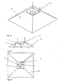
- Fig. 9 is the perspective view in which the support member 5 is formed such that four side surfaces converge in a pyramidal structure and on each of the side surfaces of the support member 5 at least one light emitting diode 1, 2, 3 and 4 is arranged.
- the carrier element 5 is designed as a square pyramid, but other pyramid structures with a base area with more than four corners are also feasible.
- Fig. 10 shows the side view of the support member 5 with the attached to a side surface of light emitting diode. 1
- Fig. 11 is the top view of the carrier element 5 with the light-emitting diodes 1, 2, 3 and 4 each attached to a side surface shown.
- Fig. 12 is the top view of the support member 5 with the light-emitting diodes 1, 2, 3 and 4 each attached to a side surface and the light distribution shown in this embodiment.
- the four light cones 7, 8, 9 and 10 are formed, which can illuminate a quadrangular surface.
- a square surface 12 are illuminated uniformly. This arrangement gives the user the opportunity to achieve a very wide-area and uniform illumination by appropriate positioning of the illuminant A. Due to the resulting square surface 12, a defined surface can be selectively illuminated and illuminated by appropriate positioning of several bulbs A at regular intervals to each other a predetermined area such as an office or a sales room evenly and energy efficient.
- FIGS. 13 to 15 another embodiment is shown.
- the support member 5 may be surrounded by a reflector 6.
- the reflector is formed by a plurality of surfaces joined to one another, which run away from the side surfaces of the carrier element 5.
- a reflector in the form of a truncated pyramid is suitable for a pyramidal carrier element 5.
- Fig. 14 shows the side view of the support member 5 with the LED attached to a side surface 1 and the reflector. 6
- Fig. 15 is the top view of the support member 5 with the ever attached to a side surface LEDs 1, 2, 3 and 4 and the reflector 6 shown.
- a light source A can also be equipped with a plurality of carrier elements 5, which are positioned in a predetermined arrangement relative to one another and each have at least two converging side surfaces on which the light emitting diodes 1 and 2 are arranged.
- the arrangement of the support elements 5 on the light source A can be done for example in a rectangular, circular or triangular arrangement or in a matrix arrangement.
- a lighting system comprising a plurality of lamps A can be constructed.
- the lamps A can be positioned in a predetermined arrangement to each other.
- a defined illumination by the lighting means can be achieved.
- the arrangement of the support elements 5 on the light source A can be done for example in a rectangular, circular or triangular arrangement or in a matrix arrangement.
- the light source A can be mounted directly in the ceiling 11 either by means of the support member 5 on the ceiling 11 or in an embodiment with a reflector 6 as a recessed light either in an embodiment without a reflector 6.
- a reflector 6 as a recessed light either in an embodiment without a reflector 6.
- the ends of the outer sides of the reflector 6 may be connected directly to the ceiling 11.
- the lamp A can be sunk in the ceiling 11 and thus can be integrated into the ceiling structure.
- Fig. 17 shows a perspective view of a support member 5 according to an embodiment of the invention.
- Fig. 18 shows a frontal view of a support element. 5
- the carrier element 5 consists in this embodiment of a heat sink 15 and at least one LED carrier 16.
- the LED carrier 16 may be formed by individual circuit boards, which are each placed on a side surface of the heat sink 15.
- the LED carrier 16 may also be formed as a prefabricated one-piece LED carrier having a polyhedron shape (for example, a pyramidal shape) and can be placed on the heat sink 15.
- an LED support 16 can be placed on each side surface of the heat sink 15. At least one light-emitting diode 1 or 2 and the electrical supply line 17 for electrical contacting of the light-emitting diode 1 or 2 is respectively applied to the LED carrier 16.
- the electrical lead 17 may be located on the top or bottom of the LED carrier 16 or within the LED carrier 16. When the electrical lead 17 is within the LED carrier 16, it may, for example, in a multilayer design of the LED carrier 16 in an inner layer of the LED carrier 16 are located.
- the LED carrier 16 with the electrical supply line 17 and the ventilation openings 19 at its side Edges, but without populated LEDs, is in Fig. 20 shown.
- light-emitting diodes which can be equipped with surface mount technology (SMT) are suitable for equipping a prefabricated LED carrier 16, which is already supplied with the electrical supply line 17.
- SMT surface mount technology
- the LED carrier 16 may for example consist of a synthetic resin material (FR4 or CEM1) or also of a ceramic substrate as LTCC structure.
- the heat sink 15 is advantageously made of a thermally highly conductive material and may also be mechanically stable.
- the heat sink 15 may consist of a ceramic substrate.
- the heat sink 15 has one or more depressions 18. These recesses 18 allow a better cooling of the carrier element 5, since they form channels through which air can flow and thus improve the heat dissipation.
- the recesses 18 extend transversely through the heat sink 15, advantageously parallel to an outer edge of the heat sink 15.
- the heat sink 15 is formed such that it consists of a plurality of juxtaposed fins. A possible embodiment of the heat sink 15 is shown in FIG Fig. 19 shown.
- the recesses 18 of the heat sink 15 may be arranged such that they form channels that use a kind of chimney effect, so that 19 can form a draft for cooling via appropriately arranged ventilation openings.
- the depressions 18 can also be seen from the direction of the lower edge of the heat sink 15 in FIG Direction of the upper end of the heat sink 15 so that the heat sink on the heat sink 15 and the LED support 16 (and thus by the light emitting diodes 1, 2) heated air and can escape through the upper vent openings 19, while over at the lower edge of the LED carrier 16 and the support member 5 existing ventilation openings 19 may enter cooler air. This air can thus be sucked by the chimney effect so to speak.
- the heat sink 15 may comprise holding means for fixing the LED carrier or carriers 16.
- cooling devices such as a heat pipe, a Peltier element or a fan.
- the LED carrier 16 advantageously has ventilation openings 19 at its lateral edges.
- the ventilation openings 19 allow an air flow below the LED carrier 16 through the recesses 18 of the heat sink 15.
- the ventilation openings 19 are arranged so that they are respectively above the recesses 18 of the heat sink 15 and thus allow optimal heat dissipation.
- the carrier element 5 can also be formed only by LED carrier 16, wherein a heat sink 15 is dispensed with.
- the LED carrier 16 itself have means for heat dissipation.
- it can have plated-through holes or integrated heat conducting layers.
- the heat conducting layers can, for example be formed in a multilayer design of the LED carrier 16 by using a metal layer.
- the metal layer may be formed, for example, by a layer within the LED carrier 16 or by the lowermost or uppermost layer of the LED carrier 16.
- the carrier element 5 can be placed on a base module 20, as shown in FIG Fig. 21 is shown.
- the base module 20 may include a portion of the drive electronics 36 for the light emitting diodes 1,2.
- a battery 38 may be housed in the base module 20.
- the attachment of the lamp A on a ceiling or on a lamp by fastening means, which has the base module 20, can be ensured.
- the support member 5 may be detachably mounted on the base module 20. It can be connected to the base module 20, for example, by a screw connection, a plug connection with barbs or else by a bayonet closure. Thus, it is possible, for example, different carrier elements 5 (with different numbers of side surfaces or light-emitting diodes) to be combined with different base modules 20 as in a modular system.
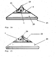
- a reflector 6 can be placed, as shown in Fig. 22 is shown.
- FIG. 23, 23a . 24 and 25 Further views of the bulb A with the base module. 20 and a reflector 6 are in the Fig. 23, 23a . 24 and 25 shown.
- a reflector 6 can be placed on the support member 5 and this surrounded.
- the reflector 6 may have openings for the light-emitting diodes 1 and 2.
- the reflector 6 has recesses 23. These recesses 23 are used for improved light control and focus the light in a predetermined, emission direction.
- the formation of the light cone 7 and 8 can be improved and, for example, the radiation angle can be set.
- the recesses 23 are formed semicircular or parabolic.
- the light-emitting diode 1 is arranged in the middle of the recess 23 or at least in the vicinity of the center.
- the light-emitting diode 1 can also be located in or near the focal point of the semicircular or parabolic recess 23, so that a large part of the light emitted from the light emitting diode 1 radiated light is concentrated in a cone of light 7.
- a section of the luminous means A with the base module 20 and a reflector 6 is in Fig. 26 shown. There, the recess 23 are shown with the light-emitting diode 1 arranged in the recess 23 and the light cone 7 produced.
- the reflector 6 may additionally have a status LED 24, which is controlled by the integrated control electronics 36 and can emit a signal in the event of a fault or for maintenance purposes.
- the status LED 24 may also output other information such as the address of the illuminant A.
- the status LED 24 can be a two-color LED are formed and thus spend different colors. The different colors can signal different states, feedbacks or even errors.
- the status LED 24 can also be arranged on the carrier element 5 and the reflector 6 can have an opening through which the status LED 24 protrudes or is visible through it. In an advantageous embodiment, the status LED 24 is arranged so that it is located at the top of the reflector 6 and at the top of the support element 5.
- the status LED 24 can also be attached to another location of the luminous means A, for example in or on the base module 20.
- the base module 20 may, for example, have the shape of a truncated pyramid and thus form an optical extension of the carrier element 5.
- the base module 20 can also have a round cross-section and, for example, have the shape of a truncated cone and thus form an optical extension of the carrier element 5 with the reflector 6 attached, as in FIG Fig. 25 shown.
- the base module 20 may for example consist of a plastic material or of a metallic material, which is preferably painted.
- the base module 20 may be connected to a bottom plate 21.
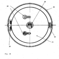
- Fig. 27 and Fig. 28 is a bottom view of the bottom plate 21, which can be inserted into the base module 20 shown.
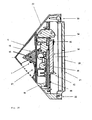
- Fig. 29 and 30 is a view of the bulb A shown in cross section.
- the base module 20 with the bottom plate 21 used may contain part of the control electronics 36 for the light-emitting diodes 1, 2. Also, a battery 38 may be housed in the base module 20. In addition, the attachment of the illuminant A on a ceiling or on a lamp by means of the bottom plate 21 by fastening means such as mounting holes 28 can be ensured.
- the bottom plate 21 may further include a cable passage 26.
- the control electronics 36 may be located on a circuit board 46.
- the board 46 may be attached either directly to the bottom plate 21 or the base module 20 or to a support plate 44.
- the support plate 44 may be located within the base module 20 and the bottom plate 21, respectively.
- the battery 38 may be secured to the support plate 44 via a releasable connection, such as a clamped connection 42, which may fix the battery 38 at one or more locations.
- the control electronics 36 may comprise contacting means 34, which are arranged for example on the board 46 or the holding plate 44.
- the bottom plate 21 may be detachably connected to the base module 20. It can be connected to the base module 20, for example, by a screw connection, a plug connection with barbs or else by a bayonet closure. A connection is also possible by connecting the bottom plate at one location to base module 20 via a pivot mechanism 30 such as a hinge, and additionally connecting it at a second location via another fixture. This further holder can be realized for example by a holder with barbs 32. Thus, it is possible to at least partially detach base plate 21 from base module 20, for example, to swap the contained battery 38, to change the wiring or contacting, or to have access to control electronics 36.
- the battery 38 which is arranged within the base module 20, can serve to supply the light-emitting diodes 1, 2.
- the supply of light emitting diodes 1,2 can be powered by the control electronics 36 from the battery 38.
- the control electronics 36 may be controllable via an interface.
- the control electronics 36 may include an interface circuit.
- the interface may be suitable for wired or wireless communication.
- the light source A and its control electronics 36 can be controlled via a DALI bus or another wired digital bus.
- the light source A and its control electronics 36 via a wireless Communication such as a wireless connection or an infrared connection are controlled.
- brightness, maintenance or status commands to and / or from the illuminant A can be sent via the interface.
- a sensor such as a temperature, brightness or color sensor, part of the control electronics 36, and information from the sensor can be transmitted via the interface.
- the brightness and / or the color reproduction of the LEDs 1, 2 can be adjusted and regulated. If the illuminant A has an interface, it is possible to control this brightness and / or the color rendering of the light-emitting diodes 1, 2.
- control electronics 36 is arranged on the board 46 in the illuminant A such that it lies in a parallel plane to the underside of the carrier element 5.
- the illuminant A may also have instead of or in addition to the bottom plate 21 via a screw or socket, via which the illuminant A can be inserted into a socket for lamps.
- This socket for lamps for example, be a socket for incandescent (eg E27), for halogen lamps or fluorescent lamps. If the bulb A via a screw or Plug-in base, it can be installed and replaced by a user without intervention in the wiring, without an electrician must perform this work.
- a lighting system comprising a plurality of lamps A can be constructed.
- the lamps A can be positioned in a predetermined arrangement to each other.
- a defined illumination by the lighting means can be achieved.
- the arrangement of the support elements 5 on the light source A can be done for example in a rectangular, circular or triangular arrangement or in a matrix arrangement. Since the carrier elements 5 are detachable from the base module 20 in a preferred embodiment, different forms of carrier elements 5 can also be combined within a lighting system, depending on the respective illumination requirement of the respective part of the room.
- a light source A with two light emitting diodes 1 and 2 are applied to the converging side surfaces of the wedge-shaped support element 5, while for the uniform illumination of a square surface 12 (such as an office space or a sales room), a support member 5 with four LEDs 1, 2, 3 and 4 can be used.
- a carrier element 5 with four side surfaces a uniform and large-area illumination of a square surface is possible, as already mentioned.
- a carrier element 5 with three side surfaces can also be used well here.
- an emergency lighting such as escape route lighting or emergency lighting can be realized.
- This illuminant A can already contain the required contacting means 34, a control electronics 36 and also optionally a battery 38 and at the same time enables a very good luminous efficacy and distribution with the most compact possible design.
- Such lamps A in a lighting system can be networked with each other via their interface and in addition to the information sent by the user, transmitted to each other information, for example, the partially contained sensors and replace ..
Landscapes
- Engineering & Computer Science (AREA)
- General Engineering & Computer Science (AREA)
- Physics & Mathematics (AREA)
- Microelectronics & Electronic Packaging (AREA)
- Optics & Photonics (AREA)
- Geometry (AREA)
- Non-Portable Lighting Devices Or Systems Thereof (AREA)
- Arrangement Of Elements, Cooling, Sealing, Or The Like Of Lighting Devices (AREA)
- Fastening Of Light Sources Or Lamp Holders (AREA)
Claims (12)
- Dispositif d'éclairage (A) comprenant- au moins deux diodes électroluminescentes (1, 2),- un élément de support sur lequel les diodes électroluminescentes (1, 2) sont disposées,
dans lequel les diodes électroluminescentes (1, 2) sont disposées sur les surfaces latérales de l'élément de support (5),
et l'élément de support (5) est positionné sur un module de base (20),
dans lequel au moins une pile (38) est intégrée dans l'élément de support (5) ou dans le module de base (20) pour alimenter les diodes électroluminescentes (1, 2), caractérisé en ce que
au moins une partie de l'électronique de commande (36), pour les diodes électroluminescentes (1, 2), est intégrée dans l'élément de support (5) ou dans le module de base (20), et
en ce que l'élément de support (5) est configuré comme un polygone dans lequel au moins quatre surfaces latérales convergent. - Dispositif d'éclairage selon la revendication 1, caractérisé en ce qu'un faisceau large est obtenu par le biais de la disposition des diodes électroluminescentes (1, 2).
- Dispositif d'éclairage selon l'une quelconque des revendications de 1 à 2, caractérisé en ce que l'élément de support (5) est entouré par un réflecteur (6).
- Dispositif d'éclairage selon la revendication 3, caractérisé en ce que le réflecteur (6) possède des renfoncements (23) utilisés pour améliorer l'orientation de la lumière et concentrer la lumière des diodes électroluminescentes (1, 2) dans une direction de faisceau prédéterminée.
- Dispositif d'éclairage selon l'une quelconque des revendications de 1 à 4, caractérisé en ce que l'élément de support (5) est formé à partir d'un matériau thermo-conducteur.
- Dispositif d'éclairage selon l'une quelconques des revendications de 1 à 5, caractérisé en ce que l'élément de support (5) est formé d'un corps de refroidissement (15) et d'au moins un support de DEL (16).
- Dispositif d'éclairage selon l'une quelconque des revendications de 1 à 6, caractérisé en ce que les lignes d'alimentation électriques (17) destinées aux diodes électroluminescentes (1, 2) sont positionnées sur l'élément de support (5), en particulier sur le support de DEL (16).
- Dispositif d'éclairage selon l'une quelconque des revendications de 1 à 7, caractérisé en ce que le module de base (20) est relié à une plaque inférieure (21).
- Dispositif d'éclairage selon l'une quelconque des revendications de 1 à 8, caractérisé en ce qu'au moins une DEL de statut (24) est disposée sur l'élément de support (5) ou sur le réflecteur (6).
- Dispositif d'éclairage selon l'une quelconque des revendications de 1 à 9, caractérisé en ce qu'aucun(e) lentille partagée ou optique similaire ou élément de recouvrement ne soit positionné(e) sur les diodes électroluminescentes (1, 2) ou le réflecteur (6).
- Éclairage de secours ayant au moins un dispositif d'éclairage (A) selon l'une quelconque des revendications de 1 à 10.
- Éclairage de secours selon la revendication 11, caractérisé en ce que l'électronique de commande (36) du dispositif d'éclairage (A) peut être respectivement commandée par une interface et en ce que les dispositifs d'éclairage (A) sont liés les uns aux autres par leurs interfaces.
Applications Claiming Priority (2)
| Application Number | Priority Date | Filing Date | Title |
|---|---|---|---|
| AT4072008 | 2008-07-24 | ||
| PCT/AT2009/000289 WO2010009491A1 (fr) | 2008-07-24 | 2009-07-24 | Élément lumineux comportant des led |
Publications (2)
| Publication Number | Publication Date |
|---|---|
| EP2307789A1 EP2307789A1 (fr) | 2011-04-13 |
| EP2307789B1 true EP2307789B1 (fr) | 2015-09-09 |
Family
ID=41569915
Family Applications (1)
| Application Number | Title | Priority Date | Filing Date |
|---|---|---|---|
| EP09775575.5A Not-in-force EP2307789B1 (fr) | 2008-07-24 | 2009-07-24 | Dispositif d'éclairage avec del |
Country Status (4)
| Country | Link |
|---|---|
| EP (1) | EP2307789B1 (fr) |
| AT (1) | AT524690B1 (fr) |
| DE (1) | DE112009001774B4 (fr) |
| WO (1) | WO2010009491A1 (fr) |
Families Citing this family (7)
| Publication number | Priority date | Publication date | Assignee | Title |
|---|---|---|---|---|
| DE102010013286B4 (de) * | 2010-03-29 | 2012-03-22 | Heraeus Noblelight Gmbh | LED-Lampe zur homogenen Ausleuchtung von Hohlkörpern |
| DE102010014128A1 (de) * | 2010-04-07 | 2011-10-13 | Vivid Chi Matter And Light Gmbh | Pendelleuchte |
| DE202011000367U1 (de) * | 2011-02-17 | 2012-05-18 | Tridonic Gmbh & Co. Kg | Kombinierte Sensor-/Notlicht-Einheit für ein Beleuchtungs-System |
| DE102011076714B4 (de) | 2011-02-17 | 2024-01-04 | Tridonic Gmbh & Co Kg | Kombinierte Sensor-/Notlicht-Einheit für ein Beleuchtungs-System |
| EP2573450B1 (fr) * | 2011-09-23 | 2014-12-10 | Hella KGaA Hueck & Co | Aéroport et système d'éclairage d'héliports |
| WO2017003399A1 (fr) * | 2015-06-29 | 2017-01-05 | Mutlu Seyit | Appareil de suspension pour luminaires |
| EP4083496A1 (fr) * | 2021-04-30 | 2022-11-02 | mawa design Licht- und Wohnideen GmbH | Logement pour un luminaire |
Family Cites Families (10)
| Publication number | Priority date | Publication date | Assignee | Title |
|---|---|---|---|---|
| US6746885B2 (en) * | 2001-08-24 | 2004-06-08 | Densen Cao | Method for making a semiconductor light source |
| TW569476B (en) * | 2001-11-16 | 2004-01-01 | Toyoda Gosei Kk | Light emitting diode, LED lighting module, and lamp apparatus |
| AU2003296485A1 (en) * | 2002-12-11 | 2004-06-30 | Charles Bolta | Light emitting diode (l.e.d.) lighting fixtures with emergency back-up and scotopic enhancement |
| US20050169006A1 (en) * | 2004-01-30 | 2005-08-04 | Harvatek Corporation | Led chip lamp apparatus |
| WO2005078338A1 (fr) * | 2004-02-17 | 2005-08-25 | Kelly William M | Lampe baladeuse |
| JP2006244725A (ja) * | 2005-02-28 | 2006-09-14 | Atex Co Ltd | Led照明装置 |
| KR100754973B1 (ko) * | 2007-04-05 | 2007-09-04 | 최만재 | 경사각을 이용한 엘이디 가로등 |
| DE202007008258U1 (de) * | 2007-04-30 | 2007-10-31 | Lumitech Produktion Und Entwicklung Gmbh | LED-Leuchtmittel |
| DE102007043904A1 (de) * | 2007-09-14 | 2009-03-19 | Osram Gesellschaft mit beschränkter Haftung | Leucht-Vorrichtung |
| DE102007043903A1 (de) * | 2007-09-14 | 2009-03-26 | Osram Gesellschaft mit beschränkter Haftung | Leucht-Vorrichtung |
-
2009
- 2009-07-24 DE DE112009001774.6T patent/DE112009001774B4/de not_active Expired - Fee Related
- 2009-07-24 AT ATA9260/2009A patent/AT524690B1/de not_active IP Right Cessation
- 2009-07-24 WO PCT/AT2009/000289 patent/WO2010009491A1/fr not_active Ceased
- 2009-07-24 EP EP09775575.5A patent/EP2307789B1/fr not_active Not-in-force
Also Published As
| Publication number | Publication date |
|---|---|
| DE112009001774B4 (de) | 2020-10-01 |
| DE112009001774A5 (de) | 2011-09-29 |
| EP2307789A1 (fr) | 2011-04-13 |
| AT524690B1 (de) | 2022-08-15 |
| WO2010009491A1 (fr) | 2010-01-28 |
| AT524690A5 (de) | 2022-08-15 |
Similar Documents
| Publication | Publication Date | Title |
|---|---|---|
| EP2307789B1 (fr) | Dispositif d'éclairage avec del | |
| DE102012222184B4 (de) | Leuchte mit Luftleitflächen | |
| DE69936375T2 (de) | Led-leuchte | |
| EP2078895B1 (fr) | Système d'éclairage | |
| DE102006018668B4 (de) | Modulares Beleuchtungssystem und Beleuchtungsanordnung | |
| EP2198196B1 (fr) | Lampe | |
| WO2009033922A2 (fr) | Dispositif d'éclairage comprenant plusieurs diodes électroluminescentes commandables | |
| DE112011106000T5 (de) | Thermomanagement für Leuchtdioden | |
| EP2612068A1 (fr) | Lampe de table ou lampadaire | |
| DE102011076128A1 (de) | Trägersystem und Lichtmodul zur Befestigung daran | |
| DE102008017271B4 (de) | Leuchte mit zwei Lichtquellen in einer Aussparung eines zumindest teilweise lichtleitenden Trägers, Verwendung dieser Leuchte als Hänge-, Wand- oder Standleuchte und Leuchtvorrichtung für eine solche Leuchte | |
| DE202011107787U1 (de) | Lichtemissionsvorrichtung | |
| AT520982A2 (de) | Leuchte, Gehäusekomponente für eine Leuchte, sowie Verfahren zur Herstellung einer Leuchte | |
| EP2384410A1 (fr) | Unité d'éclairage | |
| DE102016113941A1 (de) | LED-Modul und Lichthalterung mit selbigem | |
| EP2273185A1 (fr) | Eléments d'éclairage à DEL dotés d'un élément de guidage de la lumière | |
| EP2334983A1 (fr) | Moyen d éclairage à led | |
| WO2010133631A1 (fr) | Dissipateur thermique pour dispositif d'éclairage | |
| EP2171352B1 (fr) | Ampoule | |
| DE102014110010A1 (de) | Lichtmodul | |
| DE202011110495U1 (de) | Beleuchtungsvorrichtung und Beleuchtungseinrichtung | |
| EP1876646A2 (fr) | Luminaire à DEL | |
| DE202016107013U1 (de) | Leuchteinheit, insbesondere für eine Schirmleuchte, und Leuchte, insbesondere Schirmleuchte, mit einer Leuchteinheit | |
| DE102007056270B4 (de) | Beleuchtungseinheit mit einer LED-Lichtquelle | |
| WO2015040240A1 (fr) | Lampe |
Legal Events
| Date | Code | Title | Description |
|---|---|---|---|
| PUAI | Public reference made under article 153(3) epc to a published international application that has entered the european phase |
Free format text: ORIGINAL CODE: 0009012 |
|
| 17P | Request for examination filed |
Effective date: 20110224 |
|
| AK | Designated contracting states |
Kind code of ref document: A1 Designated state(s): AT BE BG CH CY CZ DE DK EE ES FI FR GB GR HR HU IE IS IT LI LT LU LV MC MK MT NL NO PL PT RO SE SI SK SM TR |
|
| AX | Request for extension of the european patent |
Extension state: AL BA RS |
|
| DAX | Request for extension of the european patent (deleted) | ||
| 17Q | First examination report despatched |
Effective date: 20140721 |
|
| GRAP | Despatch of communication of intention to grant a patent |
Free format text: ORIGINAL CODE: EPIDOSNIGR1 |
|
| INTG | Intention to grant announced |
Effective date: 20150327 |
|
| GRAS | Grant fee paid |
Free format text: ORIGINAL CODE: EPIDOSNIGR3 |
|
| GRAA | (expected) grant |
Free format text: ORIGINAL CODE: 0009210 |
|
| AK | Designated contracting states |
Kind code of ref document: B1 Designated state(s): AT BE BG CH CY CZ DE DK EE ES FI FR GB GR HR HU IE IS IT LI LT LU LV MC MK MT NL NO PL PT RO SE SI SK SM TR |
|
| REG | Reference to a national code |
Ref country code: GB Ref legal event code: FG4D Free format text: NOT ENGLISH |
|
| REG | Reference to a national code |
Ref country code: AT Ref legal event code: REF Ref document number: 748429 Country of ref document: AT Kind code of ref document: T Effective date: 20150915 Ref country code: CH Ref legal event code: EP |
|
| REG | Reference to a national code |
Ref country code: CH Ref legal event code: NV Representative=s name: WEINMANN ZIMMERLI, CH |
|
| REG | Reference to a national code |
Ref country code: IE Ref legal event code: FG4D Free format text: LANGUAGE OF EP DOCUMENT: GERMAN |
|
| REG | Reference to a national code |
Ref country code: DE Ref legal event code: R096 Ref document number: 502009011559 Country of ref document: DE |
|
| REG | Reference to a national code |
Ref country code: NL Ref legal event code: MP Effective date: 20150909 |
|
| PG25 | Lapsed in a contracting state [announced via postgrant information from national office to epo] |
Ref country code: LT Free format text: LAPSE BECAUSE OF FAILURE TO SUBMIT A TRANSLATION OF THE DESCRIPTION OR TO PAY THE FEE WITHIN THE PRESCRIBED TIME-LIMIT Effective date: 20150909 Ref country code: FI Free format text: LAPSE BECAUSE OF FAILURE TO SUBMIT A TRANSLATION OF THE DESCRIPTION OR TO PAY THE FEE WITHIN THE PRESCRIBED TIME-LIMIT Effective date: 20150909 Ref country code: NO Free format text: LAPSE BECAUSE OF FAILURE TO SUBMIT A TRANSLATION OF THE DESCRIPTION OR TO PAY THE FEE WITHIN THE PRESCRIBED TIME-LIMIT Effective date: 20151209 Ref country code: GR Free format text: LAPSE BECAUSE OF FAILURE TO SUBMIT A TRANSLATION OF THE DESCRIPTION OR TO PAY THE FEE WITHIN THE PRESCRIBED TIME-LIMIT Effective date: 20151210 Ref country code: LV Free format text: LAPSE BECAUSE OF FAILURE TO SUBMIT A TRANSLATION OF THE DESCRIPTION OR TO PAY THE FEE WITHIN THE PRESCRIBED TIME-LIMIT Effective date: 20150909 |
|
| REG | Reference to a national code |
Ref country code: LT Ref legal event code: MG4D |
|
| PG25 | Lapsed in a contracting state [announced via postgrant information from national office to epo] |
Ref country code: SE Free format text: LAPSE BECAUSE OF FAILURE TO SUBMIT A TRANSLATION OF THE DESCRIPTION OR TO PAY THE FEE WITHIN THE PRESCRIBED TIME-LIMIT Effective date: 20150909 Ref country code: ES Free format text: LAPSE BECAUSE OF FAILURE TO SUBMIT A TRANSLATION OF THE DESCRIPTION OR TO PAY THE FEE WITHIN THE PRESCRIBED TIME-LIMIT Effective date: 20150909 Ref country code: HR Free format text: LAPSE BECAUSE OF FAILURE TO SUBMIT A TRANSLATION OF THE DESCRIPTION OR TO PAY THE FEE WITHIN THE PRESCRIBED TIME-LIMIT Effective date: 20150909 |
|
| PG25 | Lapsed in a contracting state [announced via postgrant information from national office to epo] |
Ref country code: NL Free format text: LAPSE BECAUSE OF FAILURE TO SUBMIT A TRANSLATION OF THE DESCRIPTION OR TO PAY THE FEE WITHIN THE PRESCRIBED TIME-LIMIT Effective date: 20150909 |
|
| PG25 | Lapsed in a contracting state [announced via postgrant information from national office to epo] |
Ref country code: CZ Free format text: LAPSE BECAUSE OF FAILURE TO SUBMIT A TRANSLATION OF THE DESCRIPTION OR TO PAY THE FEE WITHIN THE PRESCRIBED TIME-LIMIT Effective date: 20150909 Ref country code: SK Free format text: LAPSE BECAUSE OF FAILURE TO SUBMIT A TRANSLATION OF THE DESCRIPTION OR TO PAY THE FEE WITHIN THE PRESCRIBED TIME-LIMIT Effective date: 20150909 Ref country code: EE Free format text: LAPSE BECAUSE OF FAILURE TO SUBMIT A TRANSLATION OF THE DESCRIPTION OR TO PAY THE FEE WITHIN THE PRESCRIBED TIME-LIMIT Effective date: 20150909 Ref country code: IT Free format text: LAPSE BECAUSE OF FAILURE TO SUBMIT A TRANSLATION OF THE DESCRIPTION OR TO PAY THE FEE WITHIN THE PRESCRIBED TIME-LIMIT Effective date: 20150909 Ref country code: IS Free format text: LAPSE BECAUSE OF FAILURE TO SUBMIT A TRANSLATION OF THE DESCRIPTION OR TO PAY THE FEE WITHIN THE PRESCRIBED TIME-LIMIT Effective date: 20160109 |
|
| PG25 | Lapsed in a contracting state [announced via postgrant information from national office to epo] |
Ref country code: RO Free format text: LAPSE BECAUSE OF FAILURE TO SUBMIT A TRANSLATION OF THE DESCRIPTION OR TO PAY THE FEE WITHIN THE PRESCRIBED TIME-LIMIT Effective date: 20150909 Ref country code: PT Free format text: LAPSE BECAUSE OF FAILURE TO SUBMIT A TRANSLATION OF THE DESCRIPTION OR TO PAY THE FEE WITHIN THE PRESCRIBED TIME-LIMIT Effective date: 20160111 Ref country code: PL Free format text: LAPSE BECAUSE OF FAILURE TO SUBMIT A TRANSLATION OF THE DESCRIPTION OR TO PAY THE FEE WITHIN THE PRESCRIBED TIME-LIMIT Effective date: 20150909 |
|
| REG | Reference to a national code |
Ref country code: DE Ref legal event code: R097 Ref document number: 502009011559 Country of ref document: DE |
|
| PLBE | No opposition filed within time limit |
Free format text: ORIGINAL CODE: 0009261 |
|
| STAA | Information on the status of an ep patent application or granted ep patent |
Free format text: STATUS: NO OPPOSITION FILED WITHIN TIME LIMIT |
|
| REG | Reference to a national code |
Ref country code: FR Ref legal event code: PLFP Year of fee payment: 8 |
|
| 26N | No opposition filed |
Effective date: 20160610 |
|
| PG25 | Lapsed in a contracting state [announced via postgrant information from national office to epo] |
Ref country code: DK Free format text: LAPSE BECAUSE OF FAILURE TO SUBMIT A TRANSLATION OF THE DESCRIPTION OR TO PAY THE FEE WITHIN THE PRESCRIBED TIME-LIMIT Effective date: 20150909 Ref country code: SI Free format text: LAPSE BECAUSE OF FAILURE TO SUBMIT A TRANSLATION OF THE DESCRIPTION OR TO PAY THE FEE WITHIN THE PRESCRIBED TIME-LIMIT Effective date: 20150909 |
|
| PGFP | Annual fee paid to national office [announced via postgrant information from national office to epo] |
Ref country code: CH Payment date: 20160727 Year of fee payment: 8 |
|
| PGFP | Annual fee paid to national office [announced via postgrant information from national office to epo] |
Ref country code: AT Payment date: 20160727 Year of fee payment: 8 |
|
| PG25 | Lapsed in a contracting state [announced via postgrant information from national office to epo] |
Ref country code: BE Free format text: LAPSE BECAUSE OF NON-PAYMENT OF DUE FEES Effective date: 20160731 |
|
| PG25 | Lapsed in a contracting state [announced via postgrant information from national office to epo] |
Ref country code: MC Free format text: LAPSE BECAUSE OF FAILURE TO SUBMIT A TRANSLATION OF THE DESCRIPTION OR TO PAY THE FEE WITHIN THE PRESCRIBED TIME-LIMIT Effective date: 20150909 |
|
| REG | Reference to a national code |
Ref country code: IE Ref legal event code: MM4A |
|
| REG | Reference to a national code |
Ref country code: FR Ref legal event code: PLFP Year of fee payment: 9 |
|
| PG25 | Lapsed in a contracting state [announced via postgrant information from national office to epo] |
Ref country code: IE Free format text: LAPSE BECAUSE OF NON-PAYMENT OF DUE FEES Effective date: 20160724 |
|
| PG25 | Lapsed in a contracting state [announced via postgrant information from national office to epo] |
Ref country code: LU Free format text: LAPSE BECAUSE OF NON-PAYMENT OF DUE FEES Effective date: 20160724 |
|
| REG | Reference to a national code |
Ref country code: CH Ref legal event code: PL |
|
| REG | Reference to a national code |
Ref country code: AT Ref legal event code: MM01 Ref document number: 748429 Country of ref document: AT Kind code of ref document: T Effective date: 20170724 |
|
| PG25 | Lapsed in a contracting state [announced via postgrant information from national office to epo] |
Ref country code: CH Free format text: LAPSE BECAUSE OF NON-PAYMENT OF DUE FEES Effective date: 20170731 Ref country code: LI Free format text: LAPSE BECAUSE OF NON-PAYMENT OF DUE FEES Effective date: 20170731 |
|
| PG25 | Lapsed in a contracting state [announced via postgrant information from national office to epo] |
Ref country code: AT Free format text: LAPSE BECAUSE OF NON-PAYMENT OF DUE FEES Effective date: 20170724 Ref country code: HU Free format text: LAPSE BECAUSE OF FAILURE TO SUBMIT A TRANSLATION OF THE DESCRIPTION OR TO PAY THE FEE WITHIN THE PRESCRIBED TIME-LIMIT; INVALID AB INITIO Effective date: 20090724 Ref country code: SM Free format text: LAPSE BECAUSE OF FAILURE TO SUBMIT A TRANSLATION OF THE DESCRIPTION OR TO PAY THE FEE WITHIN THE PRESCRIBED TIME-LIMIT Effective date: 20150909 Ref country code: CY Free format text: LAPSE BECAUSE OF FAILURE TO SUBMIT A TRANSLATION OF THE DESCRIPTION OR TO PAY THE FEE WITHIN THE PRESCRIBED TIME-LIMIT Effective date: 20150909 |
|
| PG25 | Lapsed in a contracting state [announced via postgrant information from national office to epo] |
Ref country code: MT Free format text: LAPSE BECAUSE OF FAILURE TO SUBMIT A TRANSLATION OF THE DESCRIPTION OR TO PAY THE FEE WITHIN THE PRESCRIBED TIME-LIMIT Effective date: 20150909 Ref country code: TR Free format text: LAPSE BECAUSE OF FAILURE TO SUBMIT A TRANSLATION OF THE DESCRIPTION OR TO PAY THE FEE WITHIN THE PRESCRIBED TIME-LIMIT Effective date: 20150909 Ref country code: MK Free format text: LAPSE BECAUSE OF FAILURE TO SUBMIT A TRANSLATION OF THE DESCRIPTION OR TO PAY THE FEE WITHIN THE PRESCRIBED TIME-LIMIT Effective date: 20150909 |
|
| REG | Reference to a national code |
Ref country code: FR Ref legal event code: PLFP Year of fee payment: 10 |
|
| PG25 | Lapsed in a contracting state [announced via postgrant information from national office to epo] |
Ref country code: BG Free format text: LAPSE BECAUSE OF FAILURE TO SUBMIT A TRANSLATION OF THE DESCRIPTION OR TO PAY THE FEE WITHIN THE PRESCRIBED TIME-LIMIT Effective date: 20150909 |
|
| PGFP | Annual fee paid to national office [announced via postgrant information from national office to epo] |
Ref country code: FR Payment date: 20180726 Year of fee payment: 10 |
|
| REG | Reference to a national code |
Ref country code: DE Ref legal event code: R084 Ref document number: 502009011559 Country of ref document: DE |
|
| PG25 | Lapsed in a contracting state [announced via postgrant information from national office to epo] |
Ref country code: FR Free format text: LAPSE BECAUSE OF NON-PAYMENT OF DUE FEES Effective date: 20190731 |
|
| PGFP | Annual fee paid to national office [announced via postgrant information from national office to epo] |
Ref country code: GB Payment date: 20220719 Year of fee payment: 14 Ref country code: DE Payment date: 20220527 Year of fee payment: 14 |
|
| REG | Reference to a national code |
Ref country code: DE Ref legal event code: R119 Ref document number: 502009011559 Country of ref document: DE |
|
| GBPC | Gb: european patent ceased through non-payment of renewal fee |
Effective date: 20230724 |
|
| PG25 | Lapsed in a contracting state [announced via postgrant information from national office to epo] |
Ref country code: DE Free format text: LAPSE BECAUSE OF NON-PAYMENT OF DUE FEES Effective date: 20240201 Ref country code: GB Free format text: LAPSE BECAUSE OF NON-PAYMENT OF DUE FEES Effective date: 20230724 |