EP2307840B1 - Atmosphärentauscher mit verriegelung - Google Patents
Atmosphärentauscher mit verriegelung Download PDFInfo
- Publication number
- EP2307840B1 EP2307840B1 EP09762160A EP09762160A EP2307840B1 EP 2307840 B1 EP2307840 B1 EP 2307840B1 EP 09762160 A EP09762160 A EP 09762160A EP 09762160 A EP09762160 A EP 09762160A EP 2307840 B1 EP2307840 B1 EP 2307840B1
- Authority
- EP
- European Patent Office
- Prior art keywords
- exchanger
- locking
- coupling
- male
- radial
- Prior art date
- Legal status (The legal status is an assumption and is not a legal conclusion. Google has not performed a legal analysis and makes no representation as to the accuracy of the status listed.)
- Not-in-force
Links
- 239000004033 plastic Substances 0.000 claims abstract description 15
- 229920003023 plastic Polymers 0.000 claims abstract description 15
- 239000000463 material Substances 0.000 claims abstract description 14
- 238000003780 insertion Methods 0.000 claims description 7
- 230000037431 insertion Effects 0.000 claims description 7
- 239000013529 heat transfer fluid Substances 0.000 claims description 6
- 238000007789 sealing Methods 0.000 claims description 4
- 238000004873 anchoring Methods 0.000 claims description 3
- 230000002441 reversible effect Effects 0.000 claims description 3
- 230000008878 coupling Effects 0.000 claims 29
- 238000010168 coupling process Methods 0.000 claims 29
- 238000005859 coupling reaction Methods 0.000 claims 29
- 230000000903 blocking effect Effects 0.000 claims 1
- 235000019592 roughness Nutrition 0.000 claims 1
- 239000011800 void material Substances 0.000 claims 1
- 239000002826 coolant Substances 0.000 abstract description 5
- WYTGDNHDOZPMIW-RCBQFDQVSA-N alstonine Natural products C1=CC2=C3C=CC=CC3=NC2=C2N1C[C@H]1[C@H](C)OC=C(C(=O)OC)[C@H]1C2 WYTGDNHDOZPMIW-RCBQFDQVSA-N 0.000 description 6
- 238000010101 extrusion blow moulding Methods 0.000 description 4
- 238000009434 installation Methods 0.000 description 4
- 230000002787 reinforcement Effects 0.000 description 4
- 238000010438 heat treatment Methods 0.000 description 3
- 238000000465 moulding Methods 0.000 description 3
- 229910000679 solder Inorganic materials 0.000 description 3
- 240000000966 Allium tricoccum Species 0.000 description 2
- 230000015556 catabolic process Effects 0.000 description 2
- 238000006731 degradation reaction Methods 0.000 description 2
- 238000013461 design Methods 0.000 description 2
- 235000021183 entrée Nutrition 0.000 description 2
- 239000012530 fluid Substances 0.000 description 2
- 238000012423 maintenance Methods 0.000 description 2
- 238000004519 manufacturing process Methods 0.000 description 2
- -1 polyethylene Polymers 0.000 description 2
- 238000003466 welding Methods 0.000 description 2
- 208000031968 Cadaver Diseases 0.000 description 1
- 229930040373 Paraformaldehyde Natural products 0.000 description 1
- 239000004698 Polyethylene Substances 0.000 description 1
- 230000006978 adaptation Effects 0.000 description 1
- 230000016571 aggressive behavior Effects 0.000 description 1
- 238000004378 air conditioning Methods 0.000 description 1
- XAGFODPZIPBFFR-UHFFFAOYSA-N aluminium Chemical compound [Al] XAGFODPZIPBFFR-UHFFFAOYSA-N 0.000 description 1
- 229910052782 aluminium Inorganic materials 0.000 description 1
- 238000012550 audit Methods 0.000 description 1
- 238000007664 blowing Methods 0.000 description 1
- 210000000078 claw Anatomy 0.000 description 1
- 238000002788 crimping Methods 0.000 description 1
- 230000001186 cumulative effect Effects 0.000 description 1
- 238000007599 discharging Methods 0.000 description 1
- 238000006073 displacement reaction Methods 0.000 description 1
- 238000002474 experimental method Methods 0.000 description 1
- 238000001125 extrusion Methods 0.000 description 1
- 239000011152 fibreglass Substances 0.000 description 1
- 230000012010 growth Effects 0.000 description 1
- 229920001903 high density polyethylene Polymers 0.000 description 1
- 239000004700 high-density polyethylene Substances 0.000 description 1
- 238000010102 injection blow moulding Methods 0.000 description 1
- 239000007788 liquid Substances 0.000 description 1
- 230000007774 longterm Effects 0.000 description 1
- 238000000034 method Methods 0.000 description 1
- 238000010137 moulding (plastic) Methods 0.000 description 1
- 230000002093 peripheral effect Effects 0.000 description 1
- 229920000573 polyethylene Polymers 0.000 description 1
- 229920006324 polyoxymethylene Polymers 0.000 description 1
- 230000003014 reinforcing effect Effects 0.000 description 1
- 230000000284 resting effect Effects 0.000 description 1
- 238000000926 separation method Methods 0.000 description 1
- 239000007787 solid Substances 0.000 description 1
- 238000003860 storage Methods 0.000 description 1
- 238000012546 transfer Methods 0.000 description 1
Images





Classifications
-
- F—MECHANICAL ENGINEERING; LIGHTING; HEATING; WEAPONS; BLASTING
- F28—HEAT EXCHANGE IN GENERAL
- F28D—HEAT-EXCHANGE APPARATUS, NOT PROVIDED FOR IN ANOTHER SUBCLASS, IN WHICH THE HEAT-EXCHANGE MEDIA DO NOT COME INTO DIRECT CONTACT
- F28D1/00—Heat-exchange apparatus having stationary conduit assemblies for one heat-exchange medium only, the media being in contact with different sides of the conduit wall, in which the other heat-exchange medium is a large body of fluid, e.g. domestic or motor car radiators
- F28D1/02—Heat-exchange apparatus having stationary conduit assemblies for one heat-exchange medium only, the media being in contact with different sides of the conduit wall, in which the other heat-exchange medium is a large body of fluid, e.g. domestic or motor car radiators with heat-exchange conduits immersed in the body of fluid
- F28D1/03—Heat-exchange apparatus having stationary conduit assemblies for one heat-exchange medium only, the media being in contact with different sides of the conduit wall, in which the other heat-exchange medium is a large body of fluid, e.g. domestic or motor car radiators with heat-exchange conduits immersed in the body of fluid with plate-like or laminated conduits
- F28D1/0308—Heat-exchange apparatus having stationary conduit assemblies for one heat-exchange medium only, the media being in contact with different sides of the conduit wall, in which the other heat-exchange medium is a large body of fluid, e.g. domestic or motor car radiators with heat-exchange conduits immersed in the body of fluid with plate-like or laminated conduits the conduits being formed by paired plates touching each other
- F28D1/0325—Heat-exchange apparatus having stationary conduit assemblies for one heat-exchange medium only, the media being in contact with different sides of the conduit wall, in which the other heat-exchange medium is a large body of fluid, e.g. domestic or motor car radiators with heat-exchange conduits immersed in the body of fluid with plate-like or laminated conduits the conduits being formed by paired plates touching each other the plates having lateral openings therein for circulation of the heat-exchange medium from one conduit to another
- F28D1/0333—Heat-exchange apparatus having stationary conduit assemblies for one heat-exchange medium only, the media being in contact with different sides of the conduit wall, in which the other heat-exchange medium is a large body of fluid, e.g. domestic or motor car radiators with heat-exchange conduits immersed in the body of fluid with plate-like or laminated conduits the conduits being formed by paired plates touching each other the plates having lateral openings therein for circulation of the heat-exchange medium from one conduit to another the plates having integrated connecting members
- F28D1/0341—Heat-exchange apparatus having stationary conduit assemblies for one heat-exchange medium only, the media being in contact with different sides of the conduit wall, in which the other heat-exchange medium is a large body of fluid, e.g. domestic or motor car radiators with heat-exchange conduits immersed in the body of fluid with plate-like or laminated conduits the conduits being formed by paired plates touching each other the plates having lateral openings therein for circulation of the heat-exchange medium from one conduit to another the plates having integrated connecting members with U-flow or serpentine-flow inside the conduits
-
- F—MECHANICAL ENGINEERING; LIGHTING; HEATING; WEAPONS; BLASTING
- F28—HEAT EXCHANGE IN GENERAL
- F28F—DETAILS OF HEAT-EXCHANGE AND HEAT-TRANSFER APPARATUS, OF GENERAL APPLICATION
- F28F21/00—Constructions of heat-exchange apparatus characterised by the selection of particular materials
- F28F21/06—Constructions of heat-exchange apparatus characterised by the selection of particular materials of plastics material
- F28F21/065—Constructions of heat-exchange apparatus characterised by the selection of particular materials of plastics material the heat-exchange apparatus employing plate-like or laminated conduits
- F28F21/066—Constructions of heat-exchange apparatus characterised by the selection of particular materials of plastics material the heat-exchange apparatus employing plate-like or laminated conduits for domestic or space-heating systems
-
- F—MECHANICAL ENGINEERING; LIGHTING; HEATING; WEAPONS; BLASTING
- F28—HEAT EXCHANGE IN GENERAL
- F28F—DETAILS OF HEAT-EXCHANGE AND HEAT-TRANSFER APPARATUS, OF GENERAL APPLICATION
- F28F9/00—Casings; Header boxes; Auxiliary supports for elements; Auxiliary members within casings
- F28F9/26—Arrangements for connecting different sections of heat-exchange elements, e.g. of radiators
- F28F9/262—Arrangements for connecting different sections of heat-exchange elements, e.g. of radiators for radiators
-
- F—MECHANICAL ENGINEERING; LIGHTING; HEATING; WEAPONS; BLASTING
- F28—HEAT EXCHANGE IN GENERAL
- F28F—DETAILS OF HEAT-EXCHANGE AND HEAT-TRANSFER APPARATUS, OF GENERAL APPLICATION
- F28F2275/00—Fastening; Joining
- F28F2275/14—Fastening; Joining by using form fitting connection, e.g. with tongue and groove
- F28F2275/146—Fastening; Joining by using form fitting connection, e.g. with tongue and groove with bayonet connections
-
- F—MECHANICAL ENGINEERING; LIGHTING; HEATING; WEAPONS; BLASTING
- F28—HEAT EXCHANGE IN GENERAL
- F28F—DETAILS OF HEAT-EXCHANGE AND HEAT-TRANSFER APPARATUS, OF GENERAL APPLICATION
- F28F2280/00—Mounting arrangements; Arrangements for facilitating assembling or disassembling of heat exchanger parts
- F28F2280/02—Removable elements
Definitions
- the present invention relates to an atmospheric exchanger, and more particularly to an atmospheric exchanger intended to be used in particular with a heat pump device for space heating or air conditioning.
- the document FR 2 566 107 describes an atmospheric exchanger according to the preamble of claim 1, with an inlet and a heat exchanger outlet respectively connected to a supply pipe and to a pipe for discharging a heat transfer fluid, comprising several identical unitary exchanger units which are each in the form of a panel having at least one internal serpentine tubular passage for the circulation of the coolant, said serpentine inner tubular passage having projecting end pieces sealingly connected by welding to the respective end tips of the serpentine internal tubular passages of the adjacent panels.
- Atmospheric exchangers are intended to be placed outdoors.
- the unitary heat exchanger modules are made of plastics material and are molded by extrusion blow molding. The different unitary heat exchangers are then assembled to each other in the workshop, by welding by means of a heating mirror device.
- the exchanger of the document FR 2 566 107 is packaged and transported to its installation site.
- Such an assembled exchanger is relatively fragile and bulky, which makes its transport delicate so as not to damage it. And any damage suffered by one of the exchanger unit modules renders the exchanger inoperable in its entirety.
- the exchanger inevitably undergoes dimensional variations by expansion and shrinkage depending on the external temperature to which it is subjected. It can then occur mechanical stress concentrations at the level of the links between the different unitary modules exchangers, causing breaks and the appearance of leaks, and making unusable the exchanger in its entirety. In this respect, it has been found that the solder joint does not provide sufficient reliability to guarantee satisfactory operation in the long term.
- the documents FR 1 190 414 and GB 1 305 464 describe a central heating radiator constituted by a stack of elements each comprising tubular structures of male and female connection.
- the connection of two adjacent elements is done by interlocking and then respectively solder or solder tubular structures male and female connection.
- the document GB 2,275,005 describes an end-to-end connection of two tubular structures by crimping.
- the document FR 2 918 165 describes a connection of tubular structures of male and female connection by simple interlocking or snap-fastening.
- a first problem proposed by the invention is to design an atmospheric exchanger for heat transfer liquid, able to withstand more effectively the thermal and mechanical stresses due to the variations of the external temperature and in particular to the successive expansion and withdrawal phenomena caused by these variations in temperature.
- temperature inexpensive, having a large exchange surface, easy to manufacture and transport, and can be easily and quickly adapted to lower energy requirements of each site to equip.
- the invention aims to design an atmospheric exchanger comprising a plurality of identical exchanger unit modules assembled and connected to each other in a simple, removable and interchangeable manner, limiting or eliminating any risk of heat transfer fluid leakage.
- Such an atmospheric exchanger is easy to pack and transport to an installation site without risk of damage because it can be brought in spare parts packaged and protected individually.
- connection and fixing means ensuring the connection and the fixing of the unitary modules exchangers to each other, to add or remove a number of unitary modules exchangers according to the needs of the site to be filled.
- This exchanger makes it insensitive to the risk of rupture resulting from expansion and removal, thanks to the deformation capacity of the material.
- the particular structure of the locking connection means guarantees a satisfactory seal, thanks to a sufficient resistance to internal overpressures.
- the experiment has proved withstand at pressures of the order of 2500 hPa, much higher than the holding of a mirror weld (of the order of 500 hPa).
- tubular male and female connection structures When connecting two exchanger unit modules, the tubular male and female connection structures can be connected to each other by interlocking and then locked by the reported locking pieces.
- Such a connection method is simple, fast and easy to perform by a technician at the installation site itself.
- connection means ensure the connection and attachment of the unitary modules exchangers to each other detachably.
- the tubular connection structures can be in one piece with the corresponding module body.
- a disadvantage may be that the module body is then of complex shape, more difficult to mold.
- the tubular connection structures are each constituted by a male or female plastic connection element, with an external connection section having radial locking projections and forming the projecting portion of the tubular structure of connection, and with an internal fixing section with anchoring asperities and overmolded in the corresponding module body.
- the overmoulding ensures a satisfactory mechanical strength, without risk of separation of the connecting element, and without the risk of occurrence of a leak.
- the connecting elements constitute separate parts that can each be easily made by plastic molding, whereas the module body itself, of greater volume, can be produced by extrusion blow molding of plastic material, the connecting elements constituting inserts placed in the mold before extrusion of the plastic material to achieve the exchanger unit module body. After constitution, the assembly can withstand without degradation the necessary mechanical stresses, in particular the internal overpressures of the order of 3000 hPa.
- the axial clamping ensures a good sealing of the connection after mounting, by compressing the annular sealing gasket, which makes it possible to hold the internal overpressures that can occur during use, without the appearance of leaks.
- the exchanger unit modules must be held together, away from the ground or support plane.
- the exchanger comprises support means comprising two support posts with feet and on which rests at least one spar on which are threaded and rest several connected exchange unit modules.
- the same support means can receive a variable number of exchanger unit modules, which facilitates the modularity.
- connection piece with radial protrusions adapted to be locked on a tubular male connection structure being locked by a locking piece reported.
- the exchanger comprises a locking piece comprising a ring body with insertion recesses and interlocking inner housings.
- tubular female or male connection elements makes it possible to simplify the molds, enabling the production by extrusion blow-molding unit modules exchangers, avoiding forms with undercuts complicated to achieve.
- the annular sealing gasket engaged between the tubular inserts male and female connection is preferably an O-ring.
- the latter can be housed in a front groove of the tubular insert element female connection, or in a front groove of the tubular insert male connection element.
- an atmospheric exchanger 1 is formed of the assembly of several exchanger unit modules, designated respectively by the references 10, 11, 12, 13, 14, 15, 16, 17, 18, 19, 20 and 21, stacked at following the others, and hydraulically connected with each other between an inlet 2 and an outlet 3.
- the inlet 2 is intended to be connected to an inlet supply pipe, while the outlet 3 is intended to be connected to an exhaust pipe.
- the "input” and “output” designations are only intended to distinguish the two fluid passage structures from one another. In fact, during use, it will be possible to introduce the heat transfer fluid either through the inlet 2 or the outlet 3.
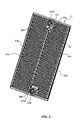
- the exchanger unit modules 10-21 are identical and each have a module body 111 in the form of a panel as illustrated in FIGS. figures 2 and 3 in relation to the exchanger unit module 11.
- the figure 2 illustrates a first face 11a of the exchanger unit module 11, while the figure 3 illustrates the second face 11b of this same exchanger unit module 11.
- the exchanger unit module 11 is a generally rectangular panel, with its large dimension intended to be positioned vertically.
- the exchanger unit module 11 comprises a module body 111, with an input structure 11c arranged substantially in the middle of the small upper side, and with an output structure 11d arranged along the lower short side and in a position slightly offset relative to in the middle of the small side.
- Vertical stiffening reinforcements 11e, 11f and 11g are made along the long vertical sides and in the middle position, on both faces 11a and 11b. According to one possibility, the stiffening reinforcements are made by blowing the plastic material to give it a tubular shape. According to another possibility, it engages in this plastic tubular structure an aluminum reinforcing tube, giving greater rectitude and rigidity to the unitary exchanger unit 11.
- the inlet structure 11c and the outlet structure 11d are hydraulically connected to each other by two internal tubular passages in parallel, namely a first internal tubular passage 11h and a second internal tubular passage 11i, formed both in coils on either side of the vertical stiffening reinforcement 11 f.
- An assembly light 11j with a square section, is arranged in a median position below the input structure 11c, and allows the passage of a spar 87 ( figure 1 ) for supporting all the exchanger unit modules 10-21 to form the exchanger 1.
- the input structure 11c is formed of two tubular connection structures, respectively 111c on the figure 2 and 211c on the figure 3 , placed in opposition to each other, hydraulically connected to each other and to the two internal tubular passages 11 h and 11 i, and each having a protruding portion which protrudes from one or other of the faces 11a and 11b.
- the outlet structure 11 d is formed of two tubular connecting structures, respectively 111d and 211d, placed in opposition to each other, hydraulically connected to each other and to the two internal tubular passages 11 h and 11i, and each having a projecting portion protruding from one or other of the faces 11a and 11b of the panel.
- the two tubular connection structures 111c and 111d that partially extend beyond the first face 11a of the panel are female-type connection structures, while the two tubular connection structures 211c and 211d that partially extend beyond the second face 11b of the panel panel are tubular connection structures of the male type.
- all the exchanger unit modules 10-21 have the same shape.
- the first visible panel 10 comprises stiffening reinforcements, and two internal tubular passages 10h and 10i.
- FIGS 4 to 8 illustrate a male connection element 30 for constituting the male connection structures 211c and 211d.
- the male connecting element 30, illustrated in the figures, is a generally tubular element with a central passage 31 crossing along an axis II for the passage of the heat transfer fluid, and with a peripheral structure of fixing and connection-locking .
- a central passage 31 crossing along an axis II for the passage of the heat transfer fluid, and with a peripheral structure of fixing and connection-locking .
- the inner fixing section 33 is shaped to ensure a mechanically resistant attachment to the body of the corresponding exchanger unit module.
- the internal fastening section 33 comprises an intermediate flange 34, an annular groove 35, and a retaining flange 36 intended to be overmoulded in the material forming the module body 111.
- the retaining flange 36 preferably has a diameter less than the diameter of the intermediate flange 34, and is ribbed on its end face to facilitate the realization of the male connecting member 30 and to achieve anti-rotation anchoring in the material of the module body 111.
- the connecting element 30 comprises an annular groove 38, with stiffening ribs for stiffening the radial protuberances 37a-37d.
- the male connection element 30 has, in its external connection-locking section 32, an annular axial protrusion 39 which protrudes axially beyond the radial locking projections 37a-37d according to an overflow DM.
- annular axial protrusion 39 has a front annular groove 39a on its front edge for receiving an annular seal 130.
- FIGS 9 to 13 illustrate a female connection element 40 for making the female connection structures 111c and 111d.
- the female connection element 40 has a generally tubular shape with an axial passage 41. Its external structure is similar to that of the male connection element 30, and there is again an external connection-locking section 42, an internal fixation section 43, an intermediate flange 44, a retaining flange 46 and an annular groove 45.
- the inner fixing section 43 is intended to be overmoulded in the material constituting the body of the exchanger unit module, ensuring a mechanically resistant attachment.
- the external connection-locking section 42 comprises radial locking protuberances 47a, 47b, 47c and 47d, shaped to correspond to the radial locking projections 37a-37d of the male connecting element 30.
- the female connection element 40 has, in its external connection-locking section 42, a front recess 49 with a flat bottom, set back from the radial protuberances 47a-47d by a distance DF slightly less than the overshoot DM.
- the radial protuberances 37a-37d of the male connecting element and the radial protuberances 47a-47d of the female connection element have substantially the same shapes, with respective bearing faces that are generally flat and resting on one end. against the other in the assembly position, and each having, opposite the bearing face, a locking face with clamping ramps.
- the radial growths 37b and 47b on the figures 5 and 10 where one distinguishes the bearing surface 137b or 147b, and the opposite locking face 237b or 247b with lateral clamping ramps 337b and 437b, or respectively 347b and 447b.
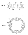
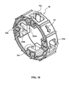
- FIGS 14 to 18 illustrate a locking piece 50 in the general shape of a ring which makes it possible to ensure the locking of the tubular structures of male and female connection, two by two.
- the locking piece 50 or more particularly the locking ring 50, is intended to be engaged around the projecting portions 37a-37d and 47a-47d of two coupled tubular connection structures, and for this purpose comprises insertion recesses 51. , 51b, 51c and 51d able to allow, in an angular position of introduction of the locking ring 50, the axial engagement of the locking ring 50 on the projecting parts of the tubular connection structures, beyond latching radial excrescences 37a-37d or 47a-47d.
- housings 51a-51d are shaped so as to allow the passage of the radial locking protrusions 37a-37d and 47a-47d during the axial displacement of the locking ring 50 on one or the other of the tubular structures of FIG. male or female connection.
- the locking ring 50 further comprises interlocking interlocking inner housing 52a, 52b, 52c and 52d shaped to allow rotation of the locking ring 50 about the radial locking protrusions 37a-37d or 47a-47d. , which enter dwellings 52a-52d.
- the locking ring 50 is in the locking angular position, the radial locking protuberances 37a-37d or 47a-47d are engaged in the locking housings 52a-52d, the side walls of which bear against the locking faces of said radial locking protuberances.
- housing 52b on the figure 18 it comprises two lateral walls 152b and 252b, the axial spacing of which is chosen to be substantially equal to the cumulative thickness of a radial protrusion of male connection element locking and a radial protrusion of locking of a female element.
- the lateral faces 152b and 252b force the corresponding radial locking protuberances to bear against each other. against each other, to ensure a mechanically resistant maintenance of the two tubular male and female connection structures.
- the locking is obtained simply by a pivoting of the locking ring 50 in the direction illustrated by the arrow 53 ( figure 18 ), while the unlocking can be obtained by a reverse rotation of the locking ring 50.
- the closure of a tubular male connection structure can be obtained by the adaptation of a shutter 60 as illustrated in FIGS. Figures 19 and 20 .
- the shutter 60 is a solid flange, with four radial locking projections 67a-67d, shaped to cooperate with corresponding radial protuberances of the tubular male connection structure and with a locking ring 50.
- positioning pins 70 are also provided on the shutter 60, which protrude axially from the end face of the connection part to engage in a corresponding recess of the opposite connecting element and block the axial rotations of the shutter 60 during locking.
- the male and female connection members 40 may advantageously be made by molding high density polyethylene, preferably with a fiberglass load.
- the module body 111 can, for its part, be produced by polyethylene injection blow molding, guaranteeing compatibility with the material of the connecting elements 30 and 40 to achieve a good weld.
- the locking ring can be made by molding a plastic material such as polyoxymethylene, guaranteeing good mechanical properties and good sliding capacity.
- plastics chosen according to their molding properties, extrusion blow molding, deformability, resistance to mechanical stresses and external aggression.
- the drive of the locking ring can be provided by hand or with a claw key.
- the heat exchanger 1 may comprise support means comprising two carrying uprights 81 and 82, each having a foot 83 or 84, and connected by a spar 87 with a square section on which the unitary heat exchangers 10-21 are threaded. , the spar crossing the lights square section 11j.
- the heat exchanger 1 may also comprise the end covers 85 and 86, fixed to the respective uprights 81 and 82, and which obscure the main external faces of the extreme unitary heat exchanger units 10 and 21, with respective side flaps 85a, 85b, 86a and 86b.
- the locking means can also be adapted for fixing a connecting piece 90 as illustrated on the Figures 21 and 22 the connecting end 90 comprises an outer tubular portion 91 and a connecting portion 92 with radial protuberances 92a-92d.
- the connecting part is shaped like that of the male connection elements 30, and can thus cooperate with the female connection elements and with a locking ring 50 for its attachment.
- the outer connecting portion 91 is suitably shaped to receive an inlet or outlet pipe.
Landscapes
- Engineering & Computer Science (AREA)
- Physics & Mathematics (AREA)
- Thermal Sciences (AREA)
- Mechanical Engineering (AREA)
- General Engineering & Computer Science (AREA)
- Heat-Exchange Devices With Radiators And Conduit Assemblies (AREA)
- Quick-Acting Or Multi-Walled Pipe Joints (AREA)
Claims (10)
- Atmosphärenwärmetauscher (1) mit einem Eingang (2) und einem Ausgang (3) für die Verbindung mit einer Zuführleitung bzw. einer Ablaufleitung für ein flüssiges Wärmeübertragungsmittel, bestehend aus mehreren, einheitlichen Wärmetauschermodulen (10-21) aus Kunststoff, von denen jedes einen plattenförmigen Modulkörper (111) mit wenigstens einer schlangenförmigen Innenrohrleitung (11h, 11i) für die Zirkulation des Wärmeübertragungsmittels hat, wobei die Enden der schlangenförmigen Innenrohrleitung (11h, 11i) eines Wärmetauschermoduls (11) dicht mit den entsprechenden Enden der schlangenförmigen Innenrohrleitung der in dem Wärmetauscher (1) anschließenden Wärmetauschermodule (10, 12) durch Verbindungs- und Befestigungsmittel verbunden sind, die eine Verbindung und Befestigung der einheitlichen Wärmetauschermodule (10-21) miteinander gewährleisten, dadurch gekennzeichnet, dass:- jedes einheitliche Wärmetauschermodul (10-21) eine Eingangssstruktur (11c) und eine Ausgangsstruktur (11d) mit jeweils einer männlichen rohrförmigen Anschlussstruktur (211c, 211d) und einer weiblichen rohrförmigen Anschlussstruktur (111c, 111d) hat, von denen ein Teil von dem zugehörigen Modulkörper (111) absteht,- die männlichen und die weiblichen rohrförmigen Anschlussstrukturen (211c, 211d) bzw. (111c, 111d) so ausgebildet sind, dass in einer Verbindungsstellung die männlichen rohrförmigen Anschlussstrukturen (211c, 211d) axial reversibel in die weiblichen rohrförmigen Anschlussstrukturen (111c, 111d) der anschließenden Wärmetauschermodule eingreifen,- die abstehenden Teile der rohrförmigen Anschlussstrukturen (111c, 211c, 111d, 211d) radiale Verriegelungsvorsprünge (37a-37d ; 47a-47d) haben,- in der Verbindungsstellung eingesetzte und abnehmbare Verriegelungsstücke (50) in Eingriff mit den radialen Verriegelungs vorsprüngen (37a-37d ; 47a-47d) der abstehenden Teile der einander benachbarten rohrförmigen Anschlussstrukturen kommen und dadurch ein Lösen verhindern.
- Wärmetauscher (1) nach Anspruch 1, dadurch gekennzeichnet, dass die rohrförmigen Anschlussstrukturen (111c, 111d, 211c, 211d) einstückig mit dem zugehörigem Modulkörper (111) ausgebildet sind.
- Wärmetauscher (1) nach Anspruch 1, dadurch gekennzeichnet, dass die rohrförmigen Anschlussstrukturen (111c, 111d, 211c, 211d) jeweils aus einem männlichen Anschlusselement (30) bzw. einen weiblichen Anschlusselement (40) aus Kunststoff mit einem äußeren Verbindungsabschnitt (32, 42) bestehen, der radiale Verriegelungsvorsprünge (37a-37d ; 47a-47d) hat und den abstehenden Teil der rohrförmigen Anschlussstruktur (111c, 111d, 211c, 211d) bildet, und mit einem inneren Befestigungsabschnitt (33, 43) mit Verankerungsrauheiten, der in den entsprechenden Modulkörper (111) eingebettet ist.
- Wärmetauscher (1) nach einem der Ansprüche 1 bis 3, dadurch gekennzeichnet, dass:- die männliche rohrförmige Anschlussstruktur (211c, 211d) in ihrem abstehenden Teil einen axialen Ringvorsprung (39) hat, der mit einem Überstand (DM) axial über die radialen Verriegelsvorsprünge (37a-37d) vorsteht,- die weibliche rohrförmige Anschlussstruktur (111c, 111d) in ihrem abstehenden Teil eine stirnseitige Vertiefung (49) mit flachem Boden hat, der mit einem Abstand (DF), der etwas geringer als der Überstand (DM) ist, hinter die radialen Verriegelungsvorsprünge (47a-47d) zurückspringt,- eine stirnseitige Ringnut (39a) am stirnseitigen Rand des axialen Vorsprungs (39) vorgesehen ist, die einen Dichtungsring (130) aufnimmt.
- Wärmetauscher (1) nach einem der Ansprüche 1 bis 4, dadurch gekennzeichnet, dass:- die männlichen und die weiblichen rohrförmigen Anschlussstrukturen (211c, 211d) bzw. (111c, 111d) jeweils dieselbe Zahl von radialen Vorsprüngen (37a-37d ; 47a-47d) haben und so ausgebildet sind, dass sie sich in der Verbindungsstellung über eine Abstützfläche (137b) aneinanderlegen,- die radialen Vorsprünge (37a-37d ; 47a-47d) auf der der Abstützfläche (137b) gegenüberliegenden Seite eine Verriegelungsfläche (237b) mit Klemmrampen (337b, 437b) haben,- die Verriegelung über einen Verriegelungsring (50) erfolgt, der die abstehenden Teile der rohrförmigen Anschlussstrukturen umgreift und innere Einführungsaussparungen (51a-51d) hat, die so ausgebildet sind, dass sie in einer Einführungswinkelstellung den axialen Eingriff des Verriegelungsringes (50) über die abstehenden Teile der ringförmigen Strukturen und über die radialen Verriegelungsvorsprünge ermöglichen, und der innere Verriegelungssitze (52a-52d) hat, die durch Drehung des Verriegelungringes (50) in Richtung auf eine Verriegelungswinkelstellung den Eingriff von Seitenwänden (152b, 252b) des Verriegelungsringes (50) über die Klemmrampen und die Verriegelungsflächen (237b) der radialen Vorsprünge (37a-37d ; 47a-47d) gewährleistet.
- Wärmetauscher nach einem der Ansprüche 1 bis 5, dadurch gekennzeichnet, dass dieser zur Abstützung zwei mit Füßen versehene Tragsäulen (81, 82) hat, auf denen wenigstens ein Längsträger (87) ruht, auf den die einheitlichen und miteinander verbundenen Wärmetauschermodule (10-21) aufgefädelt sind und ruhen.
- Wärmetauscher nach einem der Ansprüche 1 bis 6, dadurch gekennzeichnet, dass dieser ein Verschlusselement (60) mit radialen Vorsprüngen (67a-67d) hat, das dazu dient, die Öffnung einer männlichen rohrförmigen Anschlussstruktur (211c, 211d) zu verschließen, wobei es von einem aufgesteckten Verriegelungsstück (50) verriegelt wird.
- Wärmetauscher nach einem der Ansprüche 1 bis 7, dadurch gekennzeichnet, dass dieser einen Verriegelungsansatz (90) mit radialen Vorsprüngen (92a-92d) hat, der dazu dient, auf einer männlichen rohrförmigen Verriegelungsstruktur (211c, 211d) mittels eines aufgesteckten Verriegelungsstücks (50) verriegelt zu werden.
- Wärmetauscher nach einem der Ansprüche 1 bis 8, dadurch gekennzeichnet, dass dieser wenigstens ein Verriegelungsstück (50) hat, das einen Körper mit Einführungsaussparungen (51a-51d) und inneren Verriegelungssitzen (52a-52d) aufweist.
- Einheitliches Wärmetauschermodul zur Bildung eines Wärmetauscher (1) nach einem der Ansprüche 1 bis 9, dadurch gekennzeichnet, dass dieser einen plattenförmigen Modulkörper (111) aus Kunststoff hat, der zwei Innenrohrleitungen (11h, 11i) und eine Eingangsstruktur (11c) sowie eine Ausgangsstruktur (11d) hat, wobei:- die Eingangsstruktur (11c) eine weibliche rohrförmige Anschlussstruktur (111c) und eine gegenüberliegende männliche rohrförmige Anschlussstruktur (211c) hat, von denen ein abstehender Teil über eine erste Plattenfläche (11a) und über eine zweite Plattenfläche (11b) vorsteht,- die Ausgangsstruktur (11d) eine weibliche rohrförmige Anschlussstruktur (111d) sowie eine männliche rohrförmige Anschlussstruktur (211d) hat, die einander gegenüberliegen und von denen ein abstehender Teil über eine erste Plattenfläche (11a) und eine zweite Plattenfläche (11b) vorsteht,- die abstehenden Teile der rohrförmigen Anschlussstrukturen (111c, 211c, 111d, 211d) radiale Verriegelungsvorsprünge (37a-37d ; 47a-47d) haben.
Applications Claiming Priority (2)
| Application Number | Priority Date | Filing Date | Title |
|---|---|---|---|
| FR0853907A FR2932555B1 (fr) | 2008-06-12 | 2008-06-12 | Echangeur atmospherique a verrouillage |
| PCT/IB2009/052524 WO2009150633A1 (fr) | 2008-06-12 | 2009-06-12 | Echangeur atmospherique a verrouillage |
Publications (2)
| Publication Number | Publication Date |
|---|---|
| EP2307840A1 EP2307840A1 (de) | 2011-04-13 |
| EP2307840B1 true EP2307840B1 (de) | 2012-09-05 |
Family
ID=40262700
Family Applications (1)
| Application Number | Title | Priority Date | Filing Date |
|---|---|---|---|
| EP09762160A Not-in-force EP2307840B1 (de) | 2008-06-12 | 2009-06-12 | Atmosphärentauscher mit verriegelung |
Country Status (3)
| Country | Link |
|---|---|
| EP (1) | EP2307840B1 (de) |
| FR (1) | FR2932555B1 (de) |
| WO (1) | WO2009150633A1 (de) |
Families Citing this family (1)
| Publication number | Priority date | Publication date | Assignee | Title |
|---|---|---|---|---|
| FR2978538B1 (fr) * | 2011-07-25 | 2015-06-19 | Valeo Systemes Thermiques | Plaque d'echangeur de chaleur. |
Family Cites Families (5)
| Publication number | Priority date | Publication date | Assignee | Title |
|---|---|---|---|---|
| FR1190414A (fr) * | 1958-01-24 | 1959-10-12 | Dorlay Atel Du | Procédé d'assemblage des éléments de radiateurs de chauffage central |
| GB1305464A (de) * | 1970-10-13 | 1973-01-31 | ||
| FR2566107B1 (fr) * | 1984-06-15 | 1988-12-09 | Rossignol Sa | Panneau pour echangeur de chaleur, echangeur en resultant et applications, notamment aux pompes a chaleur |
| GB2275005B (en) * | 1993-02-11 | 1996-04-03 | Dimplex | Method of mass-producing an electrical column radiator |
| FR2918165B1 (fr) * | 2007-06-29 | 2013-08-16 | Dupraz En | Enchangeur atmospherique |
-
2008
- 2008-06-12 FR FR0853907A patent/FR2932555B1/fr not_active Expired - Fee Related
-
2009
- 2009-06-12 EP EP09762160A patent/EP2307840B1/de not_active Not-in-force
- 2009-06-12 WO PCT/IB2009/052524 patent/WO2009150633A1/fr not_active Ceased
Also Published As
| Publication number | Publication date |
|---|---|
| FR2932555A1 (fr) | 2009-12-18 |
| WO2009150633A1 (fr) | 2009-12-17 |
| FR2932555B1 (fr) | 2012-08-03 |
| EP2307840A1 (de) | 2011-04-13 |
Similar Documents
| Publication | Publication Date | Title |
|---|---|---|
| EP2603729B1 (de) | Undurchlässige wandstruktur | |
| EP0473474B1 (de) | Wasserkasten für einen Hauptwärmetauscher, insbesondere für Kraftfahrzeuge, der einen zweiten Wärmetauscher enthält | |
| FR2499234A1 (fr) | Echangeur de chaleur | |
| EP4121711A1 (de) | Vorrichtung zur thermischen regelung mindestens eines elektronischen bauteils | |
| EP0895017A1 (de) | Tank für unter Druck stehende Fluide | |
| EP2307840B1 (de) | Atmosphärentauscher mit verriegelung | |
| FR2918165A1 (fr) | Enchangeur atmospherique | |
| FR3122041A1 (fr) | Carter de batterie électrique étanche | |
| FR2837917A1 (fr) | Echangeur de chaleur, notamment pour un vehicule automobile, constitue d'elements tubulaires empiles | |
| EP2208010B1 (de) | Wärmetauscher für hoch- und tief-temperaturmedien | |
| FR3094470A1 (fr) | Dispositif de régulation thermique | |
| EP4659306A1 (de) | Wärmeregelungsvorrichtung für komponenten | |
| EP0867681B1 (de) | Verbindungselement, insbesondere zum Befestigen zweier Heizelemente eines Strahlungsheizkörpers | |
| FR3077128A1 (fr) | Echangeur thermique, notamment pour la regulation thermique de batteries, et procede de fabrication correspondant | |
| FR3077129A1 (fr) | Boite collectrice pour un echangeur thermique, notamment pour la regulation thermique de batteries, echangeur thermique et procede de fabrication correspondant | |
| WO2020094984A1 (fr) | Ensemble de refroisissement, notamment pour batterie de vehicule | |
| FR3092527A1 (fr) | Boitier pour dispositif de stockage d'énergie électrique pour véhicule automobile | |
| EP4549864B1 (de) | Kühlvorrichtung für eine elektrische batterie | |
| EP3707772B1 (de) | Kühlelement einer elektrischen speichervorrichtung für ein kraftfahrzeug | |
| EP2722516A1 (de) | Ansaugkrümmer mit integriertem Wärmetauscher und Verfahren zu seiner Herstellung | |
| EP4550529A1 (de) | Kühlvorrichtung für eine elektrische batterie | |
| FR3134447A1 (fr) | Echangeur thermique pour vehicule automobile | |
| WO2021123526A1 (fr) | Compartiment pour un equipement susceptible de degager de la chaleur | |
| FR3082927A1 (fr) | Boite collectrice et echangeur thermique correspondant | |
| WO2019229356A1 (fr) | Boîte collectrice pour un échangeur de chaleur |
Legal Events
| Date | Code | Title | Description |
|---|---|---|---|
| PUAI | Public reference made under article 153(3) epc to a published international application that has entered the european phase |
Free format text: ORIGINAL CODE: 0009012 |
|
| 17P | Request for examination filed |
Effective date: 20101210 |
|
| AK | Designated contracting states |
Kind code of ref document: A1 Designated state(s): AT BE BG CH CY CZ DE DK EE ES FI FR GB GR HR HU IE IS IT LI LT LU LV MC MK MT NL NO PL PT RO SE SI SK TR |
|
| AX | Request for extension of the european patent |
Extension state: AL BA RS |
|
| DAX | Request for extension of the european patent (deleted) | ||
| GRAP | Despatch of communication of intention to grant a patent |
Free format text: ORIGINAL CODE: EPIDOSNIGR1 |
|
| GRAS | Grant fee paid |
Free format text: ORIGINAL CODE: EPIDOSNIGR3 |
|
| GRAA | (expected) grant |
Free format text: ORIGINAL CODE: 0009210 |
|
| RAP1 | Party data changed (applicant data changed or rights of an application transferred) |
Owner name: THORENS ENERGIES SARL |
|
| AK | Designated contracting states |
Kind code of ref document: B1 Designated state(s): AT BE BG CH CY CZ DE DK EE ES FI FR GB GR HR HU IE IS IT LI LT LU LV MC MK MT NL NO PL PT RO SE SI SK TR |
|
| REG | Reference to a national code |
Ref country code: GB Ref legal event code: FG4D Free format text: NOT ENGLISH |
|
| REG | Reference to a national code |
Ref country code: CH Ref legal event code: EP |
|
| REG | Reference to a national code |
Ref country code: AT Ref legal event code: REF Ref document number: 574313 Country of ref document: AT Kind code of ref document: T Effective date: 20120915 |
|
| REG | Reference to a national code |
Ref country code: IE Ref legal event code: FG4D Free format text: LANGUAGE OF EP DOCUMENT: FRENCH |
|
| REG | Reference to a national code |
Ref country code: DE Ref legal event code: R096 Ref document number: 602009009535 Country of ref document: DE Effective date: 20121031 |
|
| REG | Reference to a national code |
Ref country code: AT Ref legal event code: MK05 Ref document number: 574313 Country of ref document: AT Kind code of ref document: T Effective date: 20120905 |
|
| REG | Reference to a national code |
Ref country code: NL Ref legal event code: VDEP Effective date: 20120905 |
|
| PG25 | Lapsed in a contracting state [announced via postgrant information from national office to epo] |
Ref country code: AT Free format text: LAPSE BECAUSE OF FAILURE TO SUBMIT A TRANSLATION OF THE DESCRIPTION OR TO PAY THE FEE WITHIN THE PRESCRIBED TIME-LIMIT Effective date: 20120905 Ref country code: LT Free format text: LAPSE BECAUSE OF FAILURE TO SUBMIT A TRANSLATION OF THE DESCRIPTION OR TO PAY THE FEE WITHIN THE PRESCRIBED TIME-LIMIT Effective date: 20120905 Ref country code: HR Free format text: LAPSE BECAUSE OF FAILURE TO SUBMIT A TRANSLATION OF THE DESCRIPTION OR TO PAY THE FEE WITHIN THE PRESCRIBED TIME-LIMIT Effective date: 20120905 Ref country code: FI Free format text: LAPSE BECAUSE OF FAILURE TO SUBMIT A TRANSLATION OF THE DESCRIPTION OR TO PAY THE FEE WITHIN THE PRESCRIBED TIME-LIMIT Effective date: 20120905 Ref country code: NO Free format text: LAPSE BECAUSE OF FAILURE TO SUBMIT A TRANSLATION OF THE DESCRIPTION OR TO PAY THE FEE WITHIN THE PRESCRIBED TIME-LIMIT Effective date: 20121205 |
|
| REG | Reference to a national code |
Ref country code: LT Ref legal event code: MG4D Effective date: 20120905 |
|
| PG25 | Lapsed in a contracting state [announced via postgrant information from national office to epo] |
Ref country code: GR Free format text: LAPSE BECAUSE OF FAILURE TO SUBMIT A TRANSLATION OF THE DESCRIPTION OR TO PAY THE FEE WITHIN THE PRESCRIBED TIME-LIMIT Effective date: 20121206 Ref country code: SE Free format text: LAPSE BECAUSE OF FAILURE TO SUBMIT A TRANSLATION OF THE DESCRIPTION OR TO PAY THE FEE WITHIN THE PRESCRIBED TIME-LIMIT Effective date: 20120905 Ref country code: LV Free format text: LAPSE BECAUSE OF FAILURE TO SUBMIT A TRANSLATION OF THE DESCRIPTION OR TO PAY THE FEE WITHIN THE PRESCRIBED TIME-LIMIT Effective date: 20120905 Ref country code: SI Free format text: LAPSE BECAUSE OF FAILURE TO SUBMIT A TRANSLATION OF THE DESCRIPTION OR TO PAY THE FEE WITHIN THE PRESCRIBED TIME-LIMIT Effective date: 20120905 |
|
| PG25 | Lapsed in a contracting state [announced via postgrant information from national office to epo] |
Ref country code: RO Free format text: LAPSE BECAUSE OF FAILURE TO SUBMIT A TRANSLATION OF THE DESCRIPTION OR TO PAY THE FEE WITHIN THE PRESCRIBED TIME-LIMIT Effective date: 20120905 Ref country code: EE Free format text: LAPSE BECAUSE OF FAILURE TO SUBMIT A TRANSLATION OF THE DESCRIPTION OR TO PAY THE FEE WITHIN THE PRESCRIBED TIME-LIMIT Effective date: 20120905 Ref country code: CZ Free format text: LAPSE BECAUSE OF FAILURE TO SUBMIT A TRANSLATION OF THE DESCRIPTION OR TO PAY THE FEE WITHIN THE PRESCRIBED TIME-LIMIT Effective date: 20120905 Ref country code: IS Free format text: LAPSE BECAUSE OF FAILURE TO SUBMIT A TRANSLATION OF THE DESCRIPTION OR TO PAY THE FEE WITHIN THE PRESCRIBED TIME-LIMIT Effective date: 20130105 Ref country code: NL Free format text: LAPSE BECAUSE OF FAILURE TO SUBMIT A TRANSLATION OF THE DESCRIPTION OR TO PAY THE FEE WITHIN THE PRESCRIBED TIME-LIMIT Effective date: 20120905 Ref country code: ES Free format text: LAPSE BECAUSE OF FAILURE TO SUBMIT A TRANSLATION OF THE DESCRIPTION OR TO PAY THE FEE WITHIN THE PRESCRIBED TIME-LIMIT Effective date: 20121216 |
|
| PG25 | Lapsed in a contracting state [announced via postgrant information from national office to epo] |
Ref country code: PL Free format text: LAPSE BECAUSE OF FAILURE TO SUBMIT A TRANSLATION OF THE DESCRIPTION OR TO PAY THE FEE WITHIN THE PRESCRIBED TIME-LIMIT Effective date: 20120905 Ref country code: PT Free format text: LAPSE BECAUSE OF FAILURE TO SUBMIT A TRANSLATION OF THE DESCRIPTION OR TO PAY THE FEE WITHIN THE PRESCRIBED TIME-LIMIT Effective date: 20130107 Ref country code: SK Free format text: LAPSE BECAUSE OF FAILURE TO SUBMIT A TRANSLATION OF THE DESCRIPTION OR TO PAY THE FEE WITHIN THE PRESCRIBED TIME-LIMIT Effective date: 20120905 |
|
| PLBE | No opposition filed within time limit |
Free format text: ORIGINAL CODE: 0009261 |
|
| STAA | Information on the status of an ep patent application or granted ep patent |
Free format text: STATUS: NO OPPOSITION FILED WITHIN TIME LIMIT |
|
| PG25 | Lapsed in a contracting state [announced via postgrant information from national office to epo] |
Ref country code: DK Free format text: LAPSE BECAUSE OF FAILURE TO SUBMIT A TRANSLATION OF THE DESCRIPTION OR TO PAY THE FEE WITHIN THE PRESCRIBED TIME-LIMIT Effective date: 20120905 Ref country code: BG Free format text: LAPSE BECAUSE OF FAILURE TO SUBMIT A TRANSLATION OF THE DESCRIPTION OR TO PAY THE FEE WITHIN THE PRESCRIBED TIME-LIMIT Effective date: 20121205 |
|
| 26N | No opposition filed |
Effective date: 20130606 |
|
| PG25 | Lapsed in a contracting state [announced via postgrant information from national office to epo] |
Ref country code: IT Free format text: LAPSE BECAUSE OF FAILURE TO SUBMIT A TRANSLATION OF THE DESCRIPTION OR TO PAY THE FEE WITHIN THE PRESCRIBED TIME-LIMIT Effective date: 20120905 |
|
| REG | Reference to a national code |
Ref country code: DE Ref legal event code: R097 Ref document number: 602009009535 Country of ref document: DE Effective date: 20130606 |
|
| PG25 | Lapsed in a contracting state [announced via postgrant information from national office to epo] |
Ref country code: CY Free format text: LAPSE BECAUSE OF FAILURE TO SUBMIT A TRANSLATION OF THE DESCRIPTION OR TO PAY THE FEE WITHIN THE PRESCRIBED TIME-LIMIT Effective date: 20120905 |
|
| REG | Reference to a national code |
Ref country code: CH Ref legal event code: NV Representative=s name: WAGNER PATENT AG, CH |
|
| REG | Reference to a national code |
Ref country code: IE Ref legal event code: MM4A |
|
| PG25 | Lapsed in a contracting state [announced via postgrant information from national office to epo] |
Ref country code: IE Free format text: LAPSE BECAUSE OF NON-PAYMENT OF DUE FEES Effective date: 20130612 |
|
| PG25 | Lapsed in a contracting state [announced via postgrant information from national office to epo] |
Ref country code: MT Free format text: LAPSE BECAUSE OF FAILURE TO SUBMIT A TRANSLATION OF THE DESCRIPTION OR TO PAY THE FEE WITHIN THE PRESCRIBED TIME-LIMIT Effective date: 20120905 |
|
| PG25 | Lapsed in a contracting state [announced via postgrant information from national office to epo] |
Ref country code: TR Free format text: LAPSE BECAUSE OF FAILURE TO SUBMIT A TRANSLATION OF THE DESCRIPTION OR TO PAY THE FEE WITHIN THE PRESCRIBED TIME-LIMIT Effective date: 20120905 |
|
| PG25 | Lapsed in a contracting state [announced via postgrant information from national office to epo] |
Ref country code: MK Free format text: LAPSE BECAUSE OF FAILURE TO SUBMIT A TRANSLATION OF THE DESCRIPTION OR TO PAY THE FEE WITHIN THE PRESCRIBED TIME-LIMIT Effective date: 20120905 Ref country code: HU Free format text: LAPSE BECAUSE OF FAILURE TO SUBMIT A TRANSLATION OF THE DESCRIPTION OR TO PAY THE FEE WITHIN THE PRESCRIBED TIME-LIMIT; INVALID AB INITIO Effective date: 20090612 |
|
| REG | Reference to a national code |
Ref country code: FR Ref legal event code: PLFP Year of fee payment: 8 |
|
| REG | Reference to a national code |
Ref country code: FR Ref legal event code: PLFP Year of fee payment: 9 |
|
| REG | Reference to a national code |
Ref country code: FR Ref legal event code: PLFP Year of fee payment: 10 |
|
| PGFP | Annual fee paid to national office [announced via postgrant information from national office to epo] |
Ref country code: MC Payment date: 20190626 Year of fee payment: 11 Ref country code: LU Payment date: 20190628 Year of fee payment: 11 |
|
| PGFP | Annual fee paid to national office [announced via postgrant information from national office to epo] |
Ref country code: FR Payment date: 20190624 Year of fee payment: 11 Ref country code: BE Payment date: 20190626 Year of fee payment: 11 |
|
| PGFP | Annual fee paid to national office [announced via postgrant information from national office to epo] |
Ref country code: DE Payment date: 20190822 Year of fee payment: 11 |
|
| PGFP | Annual fee paid to national office [announced via postgrant information from national office to epo] |
Ref country code: GB Payment date: 20190701 Year of fee payment: 11 |
|
| PGFP | Annual fee paid to national office [announced via postgrant information from national office to epo] |
Ref country code: CH Payment date: 20190708 Year of fee payment: 11 |
|
| REG | Reference to a national code |
Ref country code: DE Ref legal event code: R119 Ref document number: 602009009535 Country of ref document: DE |
|
| PG25 | Lapsed in a contracting state [announced via postgrant information from national office to epo] |
Ref country code: MC Free format text: LAPSE BECAUSE OF NON-PAYMENT OF DUE FEES Effective date: 20200630 |
|
| REG | Reference to a national code |
Ref country code: CH Ref legal event code: PL |
|
| GBPC | Gb: european patent ceased through non-payment of renewal fee |
Effective date: 20200612 |
|
| PG25 | Lapsed in a contracting state [announced via postgrant information from national office to epo] |
Ref country code: LU Free format text: LAPSE BECAUSE OF NON-PAYMENT OF DUE FEES Effective date: 20200612 |
|
| REG | Reference to a national code |
Ref country code: BE Ref legal event code: MM Effective date: 20200630 |
|
| PG25 | Lapsed in a contracting state [announced via postgrant information from national office to epo] |
Ref country code: CH Free format text: LAPSE BECAUSE OF NON-PAYMENT OF DUE FEES Effective date: 20200630 Ref country code: LI Free format text: LAPSE BECAUSE OF NON-PAYMENT OF DUE FEES Effective date: 20200630 Ref country code: GB Free format text: LAPSE BECAUSE OF NON-PAYMENT OF DUE FEES Effective date: 20200612 Ref country code: FR Free format text: LAPSE BECAUSE OF NON-PAYMENT OF DUE FEES Effective date: 20200630 |
|
| PG25 | Lapsed in a contracting state [announced via postgrant information from national office to epo] |
Ref country code: BE Free format text: LAPSE BECAUSE OF NON-PAYMENT OF DUE FEES Effective date: 20200630 Ref country code: DE Free format text: LAPSE BECAUSE OF NON-PAYMENT OF DUE FEES Effective date: 20210101 |