EP2307934B1 - Interface universelle pour adaptateur sans fil - Google Patents
Interface universelle pour adaptateur sans fil Download PDFInfo
- Publication number
- EP2307934B1 EP2307934B1 EP09781421.4A EP09781421A EP2307934B1 EP 2307934 B1 EP2307934 B1 EP 2307934B1 EP 09781421 A EP09781421 A EP 09781421A EP 2307934 B1 EP2307934 B1 EP 2307934B1
- Authority
- EP
- European Patent Office
- Prior art keywords
- terminal
- wireless adapter
- interface
- eeext
- supply unit
- Prior art date
- Legal status (The legal status is an assumption and is not a legal conclusion. Google has not performed a legal analysis and makes no representation as to the accuracy of the status listed.)
- Active
Links
Images



Classifications
-
- G—PHYSICS
- G05—CONTROLLING; REGULATING
- G05B—CONTROL OR REGULATING SYSTEMS IN GENERAL; FUNCTIONAL ELEMENTS OF SUCH SYSTEMS; MONITORING OR TESTING ARRANGEMENTS FOR SUCH SYSTEMS OR ELEMENTS
- G05B19/00—Program-control systems
- G05B19/02—Program-control systems electric
- G05B19/04—Program control other than numerical control, i.e. in sequence controllers or logic controllers
- G05B19/042—Program control other than numerical control, i.e. in sequence controllers or logic controllers using digital processors
- G05B19/0423—Input/output
-
- G—PHYSICS
- G05—CONTROLLING; REGULATING
- G05B—CONTROL OR REGULATING SYSTEMS IN GENERAL; FUNCTIONAL ELEMENTS OF SUCH SYSTEMS; MONITORING OR TESTING ARRANGEMENTS FOR SUCH SYSTEMS OR ELEMENTS
- G05B2219/00—Program-control systems
- G05B2219/20—Pc systems
- G05B2219/21—Pc I-O input output
- G05B2219/21116—Universal cabling; control interface between processor and devices
-
- G—PHYSICS
- G05—CONTROLLING; REGULATING
- G05B—CONTROL OR REGULATING SYSTEMS IN GENERAL; FUNCTIONAL ELEMENTS OF SUCH SYSTEMS; MONITORING OR TESTING ARRANGEMENTS FOR SUCH SYSTEMS OR ELEMENTS
- G05B2219/00—Program-control systems
- G05B2219/20—Pc systems
- G05B2219/25—Pc structure of the system
- G05B2219/25451—Connect module to bus using interface with adaptive logic
Definitions
- the invention relates to a universal interface for a wireless adapter, which supports a communication protocol used in automation technology, wherein the wireless adapter is assigned a first power supply unit for supplying power to the wireless adapter and a radio module for communicating with a higher-level control unit via a radio network.
- field devices are often used to detect and / or influence process variables.
- Sensors such as fill level measuring devices, flowmeters, pressure and temperature measuring devices, pH redox potential measuring devices, conductivity measuring devices, etc., which record the corresponding process variables level, flow, pressure, temperature, pH or conductivity, are used to record process variables.
- actuators such as valves or pumps, through which the flow of a liquid in a pipe section or the level can be changed in a container.
- field devices are all devices that are used close to the process and that provide or process process-relevant information.
- the higher-level units serve, among other things, for process control, process visualization, process monitoring and commissioning of the field devices.
- the measured values acquired by the field devices are transmitted via the connected bus system to one or possibly also to a plurality of higher-level unit (s).
- higher-level unit data transmission from the higher-level unit via the bus system to the field devices is required; this is used in particular for configuring and parameterizing field devices or for diagnostic purposes.
- the field device is operated via the bus system from the higher-level unit.
- radio network for sensors are further specified in the IEEE 802.15.4 standard.
- newer field devices in particular sensors and actuators, are partly designed as radio field devices.
- the radio unit and the power source may be provided in the field device itself or in a radio module permanently connected to the field device. The power source enables a self-sufficient power supply of the field device.
- a corresponding wireless adapter is for example in the document WO 2005/103851 A1 described.
- the wireless adapter is usually connected to a Fieldbus communication interface of the field device releasably connected. Via the fieldbus communication interface, the field device can send the data to be transmitted via the bus system to the wireless adapter, which then transmits them via radio to the destination. Conversely, the wireless adapter can receive data via radio and forward it to the field device via the fieldbus communication interface.
- the field device can be supplied with electrical power via a power supply unit of the wireless adapter.
- the communication for example, with a higher-level unit, usually handled by the wireless interface of the radio field device or the wireless adapter.
- radio field devices or wireless adapters usually have a wired communication interface.
- a wired communication interface for example, a configuration of the wireless field device or the wireless adapter via a service and / or operating unit, such as a handheld communicator, which is connected to the wired communication interface, for example, possible.
- the wired communication interface can be designed as a fieldbus communication interface, so that the communication about it is handled according to a bus system, such as according to one of the standard bus systems Profibus®, Foundation® Fieldbus or HART®.
- a fieldbus communication interface the radio field device or the wireless adapter can also be connected to a corresponding wired fieldbus.
- the power supply unit or the power source of a wireless adapter or a radio field device for example, one in the wireless adapter or the radio field device provided battery, a fuel cell, a solar power supply and / or a battery.
- the installed base contains the most diverse types of field installations: a large number of field devices are designed as 4-20mA field devices.
- the analog 4-20mA current value represents the measured value.
- the current signal may be overlaid with a digital communication, which is usually - but not limited - based on the HART protocol.
- four-wire field devices can also be subsumed under the term "field installation" in addition to the two-wire field devices;
- HMI devices which are used, for example, to parameterize the wireless adapter, or also the use of the wireless adapter in modem operation.
- a wireless adapter which is designed at least for a commonly used in automation technology protocol for digital communication, is usually tailored to the specific field installation.
- the known solution lacks the necessary flexibility to use the wireless adapter in different field installations. It is obvious that the conventional solutions are therefore very complex to implement.
- the invention has for its object to provide a universal interface for a wireless adapter that allows flexible connection options of different field installations to a wireless adapter.
- the object is achieved in that at least five terminals are provided on the interface, which are designed so that depending on the respective field installation to be connected in each case a subset of the terminals is connectable either with different configurations of field devices or with an operator panel.
- the term 'field installation' is understood to mean the differently designed types of field devices, ie two-wire or four-wire field devices;
- operating devices which are used, for example, for parameterizing the wireless adapter are also included.
- Another important application is the use of the wireless adapter in modem mode.
- the first terminal is a power supply terminal to which the power supply unit is connected.
- the second connection terminal is a first communication terminal which supports the digital communication according to the communication protocol and / or the determination of the analog current signal.
- the communication protocol preferably supports the HART standard, since HART field devices are most widely used in automation technology. It goes without saying that other common in automation technology communication protocols can be supported. Possibly. then provide additional terminals. Examples include the HART protocol, the Profibus protocol or the Foundation Fieldbus protocol.
- the 4-20 mA signal is preferably used, since this standard has prevailed in process automation technology.
- a two-wire field device fed by the energy supply unit of the wireless adapter in which the power supply and the provision of the measured value take place via the same two-wire line, is connected to the first connection terminal and to the second connection terminal.
- the power supply of the field device takes place in this case via the integrated power supply unit in the interface.
- the energy supply unit is, for example, a battery, a solar panel, a rechargeable battery or a fuel cell.
- An advantageous embodiment of the interface according to the invention provides for a third terminal, which, depending on the field installation to be connected, is either a ground terminal for an external power supply unit or a bridge which establishes the connection to the fifth terminal, which will be described in more detail below.
- a four-wire field device which is supplied with energy via a first two-wire line and an external power supply unit, is connected to the wireless adapter via the second connection terminal and the third connection terminal.
- the digital communication signal and / or the current signal representing the measured value are transmitted via the second two-wire line clamped to the second connection terminal and to the third connection terminal of the wireless adapter.
- a fourth connection terminal is a second communication terminal which supports digital communication in accordance with the respective communication protocol of the field installation.
- the fourth terminal is made in duplicate or if the two terminals work functionally the same, since they are connected to each other via a bridge.
- the two-wire field device is connected to the second terminal and to the fourth terminal and that external power supply unit is connected to the third terminal and the fourth terminal.
- a fifth terminal depending on the connected field installation is either a high-impedance ground terminal or a bridge to the third terminal.
- the wireless adapter is used in a two-wire field device for modem operation, the fourth connection terminal and the fifth connection terminal via the two communication lines on the two-wire line, the two-wire Field device connects to the external power supply unit and via which the digital communication takes place.
- the wireless adapter works in modem mode with a field device powered by the external power supply unit provided that the external power supply unit is connected to the third terminal and the fourth terminal, wherein the third terminal and the fifth terminal are connected via a bridge, and wherein the field device via the fourth terminal and the fifth terminal is connected to the wireless adapter ,
- the wireless adapter can also be connected to an HMI device via the interface for parameterization or diagnostics.
- the HMI device is connected to the fourth connection terminal and the fifth connection terminal.
- each of the terminals is assigned either a voltage limit and / or current limiting, which are designed so that when connecting the respective field installation to the wireless adapter for Available power is such that the use of the wireless adapter in connection with the field installation in potentially explosive areas is possible.
- the explosion protection is guaranteed in all applications.
- the circuit components of the interface S of the wireless adapter or the wireless adapter are identical.
- the assignment of the terminals A, B, C, Da, Db, E is changed.
- the interface S according to the invention is designed such that the individual terminals A, B, C, Da, Db, E can be used in different combinations.
- precautions have been taken in the embodiments shown which, depending on the field installation, limit the current or the voltage to permissible limit values.
- the wireless adapter which is not explicitly shown in the figures, moreover has a radio module FM, which enables wireless communication with a higher-level control unit ST via the radio network FN.
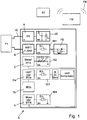
- Fig. 1 shows the assignment of the terminals A, B, C, Da, Db, E of the wireless adapter according to the invention in the case of the connection of a field device F1, which is supplied by the wireless adapter with energy through the power supply unit EE.
- the power supply unit EE also powers the wireless adapter.
- the field device F1 is thus a two-wire field device.
- Two-wire field devices are characterized in that the power supply and the transmission of the measured value, e.g. of a 4-20mA reading and / or digital communication over the same two-wire line VL.
- the first terminal A which serves as a positive pole, is the power supply terminal to which the power supply unit EE of the Wireiess adapter is connected.
- the second connection terminal B is a first communication terminal which either supports the digital communication according to the respective communication protocol, eg the HART protocol, and / or the determination of the analog current signal, in particular a 4-20 mA current signal.
- a voltage limitation UB is connected in parallel with the energy supply unit EE.
- a DC voltage is provided, which can reach a maximum of the Z voltage of the diode D (reverse direction).
- the operating voltage of the diode D in the forward direction corresponds.
- the second terminal B which represents the negative pole, has a current limit IB1 for explosion protection reasons.
- the current through the resistor R1 is limited.
- the current and voltage limitation ensures that only a power sufficient for the Ex regulations is provided at the terminals A, B.
- the analog current signal and / or the HART signal are / is about the functional unit FE to a in the Fig. 1 not shown separately transferred microprocessor.
- the functional unit FE either supports digital communication, eg HART communication or supports the measurement of the current value.
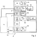
- Fig. 2 shows the assignment of the terminals A, B, C, Da, Db, E of the wireless adapter according to the invention for the case that a four-wire field device F2 is connected to the interface S of the wireless adapter.
- the field device F2 is supplied with energy by the external power supply unit EEext via the two connection lines VL1.
- the field device F2 is connected to the second connection terminal B and the third connection terminal C via the two connection lines VL2.
- the function of the terminal B and the downstream components has already been described in connection with Fig. 1 explained.
- the terminal C in this embodiment has the function of a ground terminal for the external power supply unit EEext.
- the maximum current flowing is limited by the current limit IB1.
- An additional polarity reversal protection consists of three series-connected diodes D1, D2, D3.
- the triple redundancy ensures that even if two of the three diodes fail, the protection is still working effectively.
- the diodes D1, D2, D3 furthermore have the effect that no internal capacitances or inductances act outward in the direction of the field device F2. The high safety requirements of explosion protection ex-ia are thus fulfilled.
- Fig. 3 shows occupancy of the terminals A, B, C, Da, Db, E of the wireless adapter according to the invention for the case that a two-wire field device F3 and an external power supply or an external power supply unit EEext are connected to the wireless adapter.
- the fourth terminal D is duplicated.
- the two terminals Da, Db functionally the same because they are connected to each other via a bridge Br2a, Br2b.
- the two-wire field device F3 is connected to the second connection terminal B and to the fourth connection terminal Db.
- the external power supply unit EEext is connected to the third terminal C and the fourth terminal Da.
- the wireless adapter and the field device F3 are powered by the external power supply unit EEext.
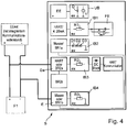
- Fig. 4 a first embodiment of the assignment of the terminals A, B, C, Da, Db, E of the wireless adapter according to the invention for the case shown that the wireless adapter works in a two-wire field device F1 in modem mode. Occupied in this embodiment, the fourth terminal Da and the fifth terminal E. The fifth terminal E, depending on the connected field installation F1, F2, EEext, BE to a high-impedance ground connection - which in the field installation of Fig. 4 the case is - or act around a bridge Br1 b, Br1a to the third terminal C.
- the wireless adapter is used in a two-wire field device F1 for modem operation
- the fourth terminal Da and the fifth terminal E are clamped on the two-wire line VL via the two communication lines KL.
- the two-wire line VL connects the two-wire field device F1 with the external power supply unit EEext and enables digital communication.
- Fig. 5 shows a second embodiment of the assignment of the terminals A, B, C, Da, Db, E of the wireless adapter according to the invention for the case that the wireless adapter works in modem mode in a four-wire field device F2.
- the power supply unit EEext which feeds the field device F2, is connected separately to the wireless adapter.
- the power supply unit EEext is connected to the third terminal C and the fourth terminal Da, in which case the third terminal C and the fifth terminal E via a bridge Br1 b, Br1 a are interconnected.
- the field device F2 is connected via the fourth connection terminal Db and the fifth connection terminal E to the wireless adapter.
- Fig. 6 the assignment of the terminals A, B, C, Da, Db, E of the wireless adapter according to the invention is shown for the case that an operating unit BE is connected to the wireless adapter.
- the operating unit BE is used, for example, for parameterizing the wireless adapter. It can also be used for commissioning or for diagnostic purposes.
- the control unit BE is connected to the wireless adapter or to the interface of the wireless adapter via the fourth terminal Da, ie the second communication terminal, and the fifth terminal E, which serves as a ground terminal.
Landscapes
- Physics & Mathematics (AREA)
- General Physics & Mathematics (AREA)
- Engineering & Computer Science (AREA)
- Automation & Control Theory (AREA)
- Arrangements For Transmission Of Measured Signals (AREA)
- Mobile Radio Communication Systems (AREA)
- Small-Scale Networks (AREA)
- Transceivers (AREA)
- Programmable Controllers (AREA)
Claims (15)
- Interface universelle (S) destinée à un adaptateur sans fil, qui prend en charge un protocole de communication (HART) courant dans la technique d'automatisation, une première unité d'alimentation en énergie (2) étant attribuée à l'adaptateur sans fil, pour l'alimentation en énergie de l'adaptateur sans fil, et un module radio (FM) pour la communication avec une unité de commande maître (ST) via un réseau radio (FN), au moins cinq bornes de raccordement (A, B, C, D, E) étant prévues sur l'interface (S), lesquelles bornes sont conçues de telle sorte qu'en fonction de l'installation de terrain (F1 F2, EEext, BE) à raccorder, un sous-ensemble des bornes de raccordement (A, B, C, D, E) peut être relié avec différentes configurations d'appareils de terrain (F1, F2) ou avec un appareil de commande (BE), ou l'adaptateur sans fil peut être utilisé en mode modem,
et pour laquelle l'occupation des bornes de raccordement (A, B, C, D, E) change selon l'installation de terrain, et les différentes bornes de raccordement (A, B, C, D, E) peuvent être utilisées dans différentes combinaisons. - Interface selon la revendication 1, pour laquelle il s'agit, concernant la première borne de raccordement (A), d'une borne d'alimentation en énergie qui est reliée avec l'unité d'alimentation en énergie (EE).
- Interface selon la revendication 1, pour laquelle il s'agit, concernant la deuxième borne de raccordement (B), d'une première borne de communication qui prend en charge la communication numérique selon le protocole de communication (HART) et/ou la détermination du signal de courant analogique (4-20 mA).
- Interface selon la revendication 2 ou 3, pour laquelle un appareil de terrain (F1) bifilaire, alimenté par l'unité d'alimentation en énergie (EE) de l'adaptateur sans fil, appareil de terrain pour lequel l'alimentation en énergie et la mise à disposition de la valeur mesurée s'effectuent sur la même ligne bifilaire (VL), peut être relié à la première borne de raccordement (A) et à la deuxième borne de raccordement (B).
- Interface selon la revendication 1, pour laquelle il s'agit, concernant la troisième borne de raccordement (C), selon l'installation de terrain (F1, F2, EEext, BE) à raccorder, d'une borne de masse pour une unité d'alimentation en énergie externe (EEext) ou d'un pont (Br1a, Br1b), qui établit la liaison avec la cinquième borne de raccordement (E).
- Interface selon la revendication 3 et 5, pour laquelle un appareil de terrain quadrifilaire (F2), qui est alimenté en énergie via une première ligne bifilaire (VL2) et une unité d'alimentation en énergie externe (EEext), peut être relié avec l'adaptateur sans fil via la deuxième borne de raccordement (B) et la troisième borne de raccordement (C), de telle sorte que le signal de communication numérique et/ou le signal de courant représentant la valeur mesurée peut être transmis via la deuxième ligne bifilaire (VL2) raccordée à la deuxième borne de raccordement (B) et à la troisième borne de raccordement (C) de l'adaptateur sans fil.
- Interface selon la revendication 1, pour laquelle il s'agit, concernant la quatrième borne de raccordement (D), d'une deuxième borne de communication qui prend en charge la communication numérique conformément au protocole de communication (HART).
- Interface selon la revendication 7, pour laquelle la quatrième borne de raccordement (D) est doublée et pour laquelle les deux bornes de raccordement (Da, Db) sont identiques d'un point de vue du fonctionnement, étant donné qu'elles sont reliées entre elles par un pont (Br2a, Br2b).
- Interface selon la revendication 3, 5 ou 7, pour laquelle, pour le cas où un appareil de terrain bifilaire (F1) et une unité d'alimentation en énergie externe (EEext) doivent être raccordés séparément à l'adaptateur sans fil, l'appareil de terrain bifilaire (F1) est raccordé à la deuxième borne de raccordement (B) et à la quatrième borne de raccordement (Db), et l'unité d'alimentation en énergie externe (EEext) est reliée avec la troisième borne de raccordement (C) et la quatrième borne de raccordement (Da).
- Interface selon la revendication 1, pour laquelle il s'agit, concernant la cinquième borne de raccordement (E), selon l'installation de terrain (F1, F2, EEext, BE) raccordée, d'une connexion de masse de haute impédance ou d'un pont (Br1 b, Br1 a) avec la troisième borne de raccordement (C).
- Interface selon l'une ou plusieurs des revendications 7 ou 8 et 10, pour laquelle, pour le cas où l'adaptateur sans fil est utilisé dans le cas d'un appareil de terrain bifilaire (F1) pour le mode modem, la quatrième borne de raccordement (Da) et la cinquième borne de raccordement (E) sont raccordées par l'intermédiaire des deux lignes de communication (KL) sur le câble bifilaire (VL), qui relie l'appareil de terrain bifilaire (F1) avec l'unité d'alimentation en énergie externe (EEext) et par l'intermédiaire duquel s'effectue la communication numérique.
- Interface selon la revendication 5, 7 et 10, pour laquelle, pour le cas où l'adaptateur sans fil fonctionne en mode modem dans le cas d'un appareil de terrain (F2) alimenté via l'unité d'alimentation en énergie externe (EEext), l'unité d'alimentation en énergie externe (EEext) est interconnectée avec la troisième borne de raccordement (C) et la cinquième borne de raccordement (E) par l'intermédiaire d'un pont (Br1 a, Br1 b), et pour laquelle l'appareil de terrain (F2) est raccordé à l'adaptateur sans fil via la quatrième borne de raccordement (Db) et la cinquième borne de raccordement (E).
- Interface selon la revendication 7 et 10, pour laquelle, pour le cas où l'adaptateur sans fil est utilisé au moyen d'un appareil de commande (BE), l'appareil de commande (BE) peut être raccordé à la quatrième borne de raccordement (Da) à et la cinquième borne de raccordement (E).
- Interface selon l'une ou plusieurs des revendications précédentes, pour laquelle chacune des bornes de raccordement (A, B, C, D, E) se voit attribuer une limitation de tension (UB) et/ou une limitation de courant (IB), qui est/sont conçue(s) de telle sorte que lors du raccordement de l'installation de terrain (F1, F2, EEext, BE) respective à l'adaptateur sans fil, la puissance disponible est dimensionnée de telle sorte que l'utilisation de l'adaptateur sans fil soit possible en liaison avec l'installation de terrain (F1, F2, EEext, BE) dans la zone à atmosphère explosible.
- Interface selon la revendication 1, pour laquelle il s'agit, concernant le protocole de communication, du protocole HART, du protocole Profibus ou du protocole Foundation Fieldbus.
Applications Claiming Priority (2)
| Application Number | Priority Date | Filing Date | Title |
|---|---|---|---|
| DE200810036967 DE102008036967A1 (de) | 2008-08-08 | 2008-08-08 | Universelle Schnittstelle für einen Wireless Adapter |
| PCT/EP2009/060031 WO2010015601A1 (fr) | 2008-08-08 | 2009-08-03 | Interface universelle pour adaptateur sans fil |
Publications (2)
| Publication Number | Publication Date |
|---|---|
| EP2307934A1 EP2307934A1 (fr) | 2011-04-13 |
| EP2307934B1 true EP2307934B1 (fr) | 2018-06-20 |
Family
ID=41258305
Family Applications (1)
| Application Number | Title | Priority Date | Filing Date |
|---|---|---|---|
| EP09781421.4A Active EP2307934B1 (fr) | 2008-08-08 | 2009-08-03 | Interface universelle pour adaptateur sans fil |
Country Status (6)
| Country | Link |
|---|---|
| US (1) | US8902801B2 (fr) |
| EP (1) | EP2307934B1 (fr) |
| CN (1) | CN102112932B (fr) |
| CA (1) | CA2732935C (fr) |
| DE (1) | DE102008036967A1 (fr) |
| WO (1) | WO2010015601A1 (fr) |
Families Citing this family (20)
| Publication number | Priority date | Publication date | Assignee | Title |
|---|---|---|---|---|
| DE102009047535B4 (de) * | 2009-12-04 | 2023-12-07 | Endress + Hauser Process Solutions Ag | Verfahren zum Ermitteln einer Anschlusskonfiguration eines Feldgerätes an einem Wireless Adapter |
| DE102011076708A1 (de) | 2011-05-30 | 2012-12-06 | Endress + Hauser Process Solutions Ag | Funkeinheit mit einer Versorgungsschaltung zur Spannungsversorgung und Verfahren zum Betreiben einer solchen Funkeinheit |
| DE102011076706A1 (de) | 2011-05-30 | 2012-12-06 | Endress + Hauser Process Solutions Ag | Elektrische und/oder elektronische Versorgungsschaltung und Verfahren zum Bereitstellen einer Versorgungsspannung |
| DE102011086396A1 (de) * | 2011-11-15 | 2013-05-16 | Endress + Hauser Wetzer Gmbh + Co Kg | Verfahren zur Datenübertragung zwischen einem Feldgerät der Prozessautomatisierungstechnik und einer entfernten Datenverarbeitungseinrichtung |
| DE102012012431A1 (de) * | 2012-06-25 | 2014-01-02 | Robert Bosch Gmbh | Kommunikationsvorrichtung und Kommunikationsverfahren |
| DE102012111018A1 (de) * | 2012-11-15 | 2014-05-15 | Systemplan GmbH | Mehrkanaliges Messdatenerfassungsgerät |
| DE102012112635B4 (de) * | 2012-12-19 | 2025-01-30 | Endress+Hauser Process Solutions Ag | Funkmodul für ein Feldgerät |
| DE102014000679A1 (de) * | 2014-01-22 | 2015-07-23 | Phoenix Contact Gmbh & Co. Kg | Verbindungsadaptersystem der Steuerungstechnik |
| DE102014105913A1 (de) * | 2014-04-28 | 2015-10-29 | Phoenix Contact Gmbh & Co. Kg | Parametrisierbares Energieversorgungsgerät |
| CN105488977A (zh) * | 2015-12-08 | 2016-04-13 | 上海工业自动化仪表研究院 | 一种现场仪表自取电式无线适配系统 |
| DE102017114851A1 (de) * | 2017-07-04 | 2019-01-10 | Endress+Hauser SE+Co. KG | Feldgeräteadapter zur drahtlosen Datenübertragung |
| DE102017121923B4 (de) | 2017-09-21 | 2019-12-19 | Vega Grieshaber Kg | Messanordnung mit einem Bediengerät und Verfahren zum Betreiben einer solchen Messanordnung |
| DE102018110101A1 (de) * | 2018-04-26 | 2019-10-31 | Endress+Hauser SE+Co. KG | Ansteckbares Funkmodul der Automatisierungstechnik |
| JP7192290B2 (ja) | 2018-07-27 | 2022-12-20 | 横河電機株式会社 | 通信装置およびシステム |
| DE102018122014A1 (de) | 2018-09-10 | 2020-03-12 | Endress + Hauser Flowtec Ag | Meßgeräte-System sowie damit gebildete Meßanordnung |
| DE102018131685A1 (de) | 2018-12-11 | 2020-06-18 | Endress+Hauser SE+Co. KG | Feldgeräteadapter zur drahtlosen Datenübertragung |
| DE102019116193A1 (de) * | 2019-06-14 | 2020-12-17 | Endress+Hauser SE+Co. KG | Feldgerät der Automatisierungstechnik |
| DE102019118839A1 (de) * | 2019-07-11 | 2021-01-14 | Endress+Hauser SE+Co. KG | Verfahren zum Betreiben eines Feldgerätes der Automatisierungstechnik |
| DE102019125150A1 (de) | 2019-09-18 | 2021-03-18 | Endress + Hauser Wetzer Gmbh + Co. Kg | Feldgerät |
| DE102020105605A1 (de) | 2020-03-03 | 2021-09-09 | Endress+Hauser SE+Co. KG | Feldgeräteadapter zur drahtlosen Datenübertragung |
Citations (1)
| Publication number | Priority date | Publication date | Assignee | Title |
|---|---|---|---|---|
| EP1925918A2 (fr) * | 2006-11-27 | 2008-05-28 | VEGA Grieshaber KG | Boite de connection pour la transmission d'un signal |
Family Cites Families (12)
| Publication number | Priority date | Publication date | Assignee | Title |
|---|---|---|---|---|
| US7228186B2 (en) * | 2000-05-12 | 2007-06-05 | Rosemount Inc. | Field-mounted process device with programmable digital/analog interface |
| DE10113676A1 (de) * | 2001-03-21 | 2002-09-26 | Abb Research Ltd | System mit Sensor oder Aktor mit abtrennbarem drahtlosem Kommunikationsmodul |
| US7035773B2 (en) * | 2002-03-06 | 2006-04-25 | Fisher-Rosemount Systems, Inc. | Appendable system and devices for data acquisition, analysis and control |
| US7080544B2 (en) * | 2002-08-23 | 2006-07-25 | Firemaster Oilfield Services Inc. | Apparatus system and method for gas well site monitoring |
| US7096073B2 (en) * | 2003-09-22 | 2006-08-22 | Creo Il, Ltd. | Configurable controller |
| CN100507781C (zh) * | 2004-03-02 | 2009-07-01 | 罗斯蒙德公司 | 具有可编程数字/模拟接口的现场安装过程设备 |
| DE102004020393A1 (de) | 2004-04-23 | 2005-11-10 | Endress + Hauser Gmbh + Co. Kg | Funkmodul für Feldgeräte der Automatisierungstechnik |
| US8538560B2 (en) * | 2004-04-29 | 2013-09-17 | Rosemount Inc. | Wireless power and communication unit for process field devices |
| JP4792851B2 (ja) * | 2004-11-01 | 2011-10-12 | 横河電機株式会社 | フィールド機器 |
| US7421531B2 (en) * | 2005-01-12 | 2008-09-02 | Rosemount Inc. | Isolating system that couples fieldbus data to a network |
| DE102006055900B4 (de) * | 2005-12-27 | 2011-08-25 | VEGA Grieshaber KG, 77709 | Schnittstellenadapter |
| EP2005651B1 (fr) * | 2006-04-12 | 2010-09-08 | VEGA Grieshaber KG | Appareil d'emission et de reception pour la transmission sans fil de signaux d'appareil de terrain |
-
2008
- 2008-08-08 DE DE200810036967 patent/DE102008036967A1/de not_active Withdrawn
-
2009
- 2009-08-03 US US12/451,952 patent/US8902801B2/en active Active
- 2009-08-03 EP EP09781421.4A patent/EP2307934B1/fr active Active
- 2009-08-03 CA CA2732935A patent/CA2732935C/fr active Active
- 2009-08-03 WO PCT/EP2009/060031 patent/WO2010015601A1/fr not_active Ceased
- 2009-08-03 CN CN200980130736.8A patent/CN102112932B/zh active Active
Patent Citations (1)
| Publication number | Priority date | Publication date | Assignee | Title |
|---|---|---|---|---|
| EP1925918A2 (fr) * | 2006-11-27 | 2008-05-28 | VEGA Grieshaber KG | Boite de connection pour la transmission d'un signal |
Also Published As
| Publication number | Publication date |
|---|---|
| US8902801B2 (en) | 2014-12-02 |
| US20110134817A1 (en) | 2011-06-09 |
| CN102112932A (zh) | 2011-06-29 |
| CA2732935C (fr) | 2016-09-20 |
| CN102112932B (zh) | 2013-12-25 |
| WO2010015601A1 (fr) | 2010-02-11 |
| EP2307934A1 (fr) | 2011-04-13 |
| DE102008036967A1 (de) | 2010-02-11 |
| CA2732935A1 (fr) | 2010-02-11 |
Similar Documents
| Publication | Publication Date | Title |
|---|---|---|
| EP2307934B1 (fr) | Interface universelle pour adaptateur sans fil | |
| EP1860513B1 (fr) | Circuit destiné à la transmission sécurisée d'une valeur de signal analogique | |
| EP2984530B1 (fr) | Appareil d'alimentation d'un transducteur de mesure, système destiné à être utilisé dans les techniques d'automatisation, et procédé d'utilisation dudit système | |
| EP3170287B1 (fr) | Système de commande et de transmission de données, module de passerelle, module e/a et procédé de commande de processus | |
| DE102012014681B4 (de) | Verwendung eines lO-Links zur Anbindung eines Netzgerätes | |
| DE102011006590B4 (de) | Verfahren zum Betreiben eines Gateways | |
| EP3025318B1 (fr) | Appareil de mesure doté d'une électronique de fonctionnement et de mesure commutable servant à la communication d'un signal de mesure | |
| CH702454A1 (de) | Anordnung mit einer übergeordneten Steuereinheit und zumindest einem mit der Steuereinheit verbindbaren intelligenten Feldgerät. | |
| EP2307931B1 (fr) | Appareil de terrain autonome ou adaptateur radio autonome pour un appareil de terrain de la technologie d'automatisation | |
| EP2340468A1 (fr) | Appareil de terrain autonome | |
| EP3283928B1 (fr) | Procédé de branchement ou de débranchement automatique d'une résistance de communication d'un dispositif hart | |
| WO2011067070A2 (fr) | Procédé de détermination d'une configuration de connexion d'un appareil de terrain à un adaptateur sans-fil | |
| EP3465364A1 (fr) | Adaptateur radio pour un appareil de terrain pourvu d'une antenne pour deux normes de communication | |
| EP3821308B1 (fr) | Système permettant de collecter des données présentes dans une installation utilisant des techniques d'automatisation | |
| WO2018184766A1 (fr) | Appareil de terrain de la technique d'automatisation à alimentation électrique par câble ethernet | |
| DE102014105292B4 (de) | Vorrichtung und System zum Bedienen eines Feldgerätes | |
| DE102017213365B4 (de) | Kommunikationsvorrichtung, System und Verfahren | |
| DE102011086054B4 (de) | System zur Sicherstellung der Verfügbarkeit eines Bussystems der Automatisierungstechnik | |
| DE102009054800A1 (de) | Anordnung zur applikationsspezifischen Aufbereitung und Verfügbarmachung von gerätespezifischen Informationen eines Feldgeräts | |
| EP2316195A1 (fr) | Dispositif pour commander un appareil de terrain qui est intégré dans un réseau radioélectrique en automatisme | |
| WO2021239350A1 (fr) | Appareil de terrain pour vérifier la qualité d'une connexion réseau | |
| EP3153938B1 (fr) | Dispositif de mesure | |
| DE102012110999A1 (de) | Verfahren zum Betreiben einer Anzeigeeinheit zur Anzeige von Prozessdaten | |
| DE202013100798U1 (de) | Universal-Steuereinheit mit BUS- und WEB-Anbindung |
Legal Events
| Date | Code | Title | Description |
|---|---|---|---|
| PUAI | Public reference made under article 153(3) epc to a published international application that has entered the european phase |
Free format text: ORIGINAL CODE: 0009012 |
|
| 17P | Request for examination filed |
Effective date: 20110113 |
|
| AK | Designated contracting states |
Kind code of ref document: A1 Designated state(s): AT BE BG CH CY CZ DE DK EE ES FI FR GB GR HR HU IE IS IT LI LT LU LV MC MK MT NL NO PL PT RO SE SI SK SM TR |
|
| AX | Request for extension of the european patent |
Extension state: AL BA RS |
|
| RIN1 | Information on inventor provided before grant (corrected) |
Inventor name: FIEDLER, MARC Inventor name: PROBST, STEFAN |
|
| DAX | Request for extension of the european patent (deleted) | ||
| 17Q | First examination report despatched |
Effective date: 20160414 |
|
| RAP1 | Party data changed (applicant data changed or rights of an application transferred) |
Owner name: ENDRESS+HAUSER PROCESS SOLUTIONS AG |
|
| GRAP | Despatch of communication of intention to grant a patent |
Free format text: ORIGINAL CODE: EPIDOSNIGR1 |
|
| INTG | Intention to grant announced |
Effective date: 20180212 |
|
| GRAS | Grant fee paid |
Free format text: ORIGINAL CODE: EPIDOSNIGR3 |
|
| GRAA | (expected) grant |
Free format text: ORIGINAL CODE: 0009210 |
|
| AK | Designated contracting states |
Kind code of ref document: B1 Designated state(s): AT BE BG CH CY CZ DE DK EE ES FI FR GB GR HR HU IE IS IT LI LT LU LV MC MK MT NL NO PL PT RO SE SI SK SM TR |
|
| REG | Reference to a national code |
Ref country code: GB Ref legal event code: FG4D Free format text: NOT ENGLISH |
|
| REG | Reference to a national code |
Ref country code: IE Ref legal event code: FG4D Free format text: LANGUAGE OF EP DOCUMENT: GERMAN |
|
| REG | Reference to a national code |
Ref country code: AT Ref legal event code: REF Ref document number: 1011043 Country of ref document: AT Kind code of ref document: T Effective date: 20180715 |
|
| REG | Reference to a national code |
Ref country code: DE Ref legal event code: R096 Ref document number: 502009015043 Country of ref document: DE |
|
| REG | Reference to a national code |
Ref country code: FR Ref legal event code: PLFP Year of fee payment: 10 |
|
| REG | Reference to a national code |
Ref country code: NL Ref legal event code: FP |
|
| PG25 | Lapsed in a contracting state [announced via postgrant information from national office to epo] |
Ref country code: NO Free format text: LAPSE BECAUSE OF FAILURE TO SUBMIT A TRANSLATION OF THE DESCRIPTION OR TO PAY THE FEE WITHIN THE PRESCRIBED TIME-LIMIT Effective date: 20180920 Ref country code: SE Free format text: LAPSE BECAUSE OF FAILURE TO SUBMIT A TRANSLATION OF THE DESCRIPTION OR TO PAY THE FEE WITHIN THE PRESCRIBED TIME-LIMIT Effective date: 20180620 Ref country code: BG Free format text: LAPSE BECAUSE OF FAILURE TO SUBMIT A TRANSLATION OF THE DESCRIPTION OR TO PAY THE FEE WITHIN THE PRESCRIBED TIME-LIMIT Effective date: 20180920 Ref country code: LT Free format text: LAPSE BECAUSE OF FAILURE TO SUBMIT A TRANSLATION OF THE DESCRIPTION OR TO PAY THE FEE WITHIN THE PRESCRIBED TIME-LIMIT Effective date: 20180620 Ref country code: FI Free format text: LAPSE BECAUSE OF FAILURE TO SUBMIT A TRANSLATION OF THE DESCRIPTION OR TO PAY THE FEE WITHIN THE PRESCRIBED TIME-LIMIT Effective date: 20180620 |
|
| REG | Reference to a national code |
Ref country code: LT Ref legal event code: MG4D |
|
| PG25 | Lapsed in a contracting state [announced via postgrant information from national office to epo] |
Ref country code: LV Free format text: LAPSE BECAUSE OF FAILURE TO SUBMIT A TRANSLATION OF THE DESCRIPTION OR TO PAY THE FEE WITHIN THE PRESCRIBED TIME-LIMIT Effective date: 20180620 Ref country code: HR Free format text: LAPSE BECAUSE OF FAILURE TO SUBMIT A TRANSLATION OF THE DESCRIPTION OR TO PAY THE FEE WITHIN THE PRESCRIBED TIME-LIMIT Effective date: 20180620 Ref country code: GR Free format text: LAPSE BECAUSE OF FAILURE TO SUBMIT A TRANSLATION OF THE DESCRIPTION OR TO PAY THE FEE WITHIN THE PRESCRIBED TIME-LIMIT Effective date: 20180921 |
|
| PG25 | Lapsed in a contracting state [announced via postgrant information from national office to epo] |
Ref country code: IS Free format text: LAPSE BECAUSE OF FAILURE TO SUBMIT A TRANSLATION OF THE DESCRIPTION OR TO PAY THE FEE WITHIN THE PRESCRIBED TIME-LIMIT Effective date: 20181020 Ref country code: EE Free format text: LAPSE BECAUSE OF FAILURE TO SUBMIT A TRANSLATION OF THE DESCRIPTION OR TO PAY THE FEE WITHIN THE PRESCRIBED TIME-LIMIT Effective date: 20180620 Ref country code: PL Free format text: LAPSE BECAUSE OF FAILURE TO SUBMIT A TRANSLATION OF THE DESCRIPTION OR TO PAY THE FEE WITHIN THE PRESCRIBED TIME-LIMIT Effective date: 20180620 Ref country code: RO Free format text: LAPSE BECAUSE OF FAILURE TO SUBMIT A TRANSLATION OF THE DESCRIPTION OR TO PAY THE FEE WITHIN THE PRESCRIBED TIME-LIMIT Effective date: 20180620 Ref country code: CZ Free format text: LAPSE BECAUSE OF FAILURE TO SUBMIT A TRANSLATION OF THE DESCRIPTION OR TO PAY THE FEE WITHIN THE PRESCRIBED TIME-LIMIT Effective date: 20180620 Ref country code: SK Free format text: LAPSE BECAUSE OF FAILURE TO SUBMIT A TRANSLATION OF THE DESCRIPTION OR TO PAY THE FEE WITHIN THE PRESCRIBED TIME-LIMIT Effective date: 20180620 |
|
| PG25 | Lapsed in a contracting state [announced via postgrant information from national office to epo] |
Ref country code: SM Free format text: LAPSE BECAUSE OF FAILURE TO SUBMIT A TRANSLATION OF THE DESCRIPTION OR TO PAY THE FEE WITHIN THE PRESCRIBED TIME-LIMIT Effective date: 20180620 Ref country code: ES Free format text: LAPSE BECAUSE OF FAILURE TO SUBMIT A TRANSLATION OF THE DESCRIPTION OR TO PAY THE FEE WITHIN THE PRESCRIBED TIME-LIMIT Effective date: 20180620 |
|
| REG | Reference to a national code |
Ref country code: DE Ref legal event code: R097 Ref document number: 502009015043 Country of ref document: DE |
|
| PG25 | Lapsed in a contracting state [announced via postgrant information from national office to epo] |
Ref country code: MC Free format text: LAPSE BECAUSE OF FAILURE TO SUBMIT A TRANSLATION OF THE DESCRIPTION OR TO PAY THE FEE WITHIN THE PRESCRIBED TIME-LIMIT Effective date: 20180620 |
|
| REG | Reference to a national code |
Ref country code: CH Ref legal event code: PL |
|
| PLBE | No opposition filed within time limit |
Free format text: ORIGINAL CODE: 0009261 |
|
| STAA | Information on the status of an ep patent application or granted ep patent |
Free format text: STATUS: NO OPPOSITION FILED WITHIN TIME LIMIT |
|
| PG25 | Lapsed in a contracting state [announced via postgrant information from national office to epo] |
Ref country code: CH Free format text: LAPSE BECAUSE OF NON-PAYMENT OF DUE FEES Effective date: 20180831 Ref country code: LI Free format text: LAPSE BECAUSE OF NON-PAYMENT OF DUE FEES Effective date: 20180831 Ref country code: LU Free format text: LAPSE BECAUSE OF NON-PAYMENT OF DUE FEES Effective date: 20180803 |
|
| REG | Reference to a national code |
Ref country code: BE Ref legal event code: MM Effective date: 20180831 |
|
| 26N | No opposition filed |
Effective date: 20190321 |
|
| REG | Reference to a national code |
Ref country code: IE Ref legal event code: MM4A |
|
| PG25 | Lapsed in a contracting state [announced via postgrant information from national office to epo] |
Ref country code: DK Free format text: LAPSE BECAUSE OF FAILURE TO SUBMIT A TRANSLATION OF THE DESCRIPTION OR TO PAY THE FEE WITHIN THE PRESCRIBED TIME-LIMIT Effective date: 20180620 |
|
| PG25 | Lapsed in a contracting state [announced via postgrant information from national office to epo] |
Ref country code: IE Free format text: LAPSE BECAUSE OF NON-PAYMENT OF DUE FEES Effective date: 20180803 |
|
| PG25 | Lapsed in a contracting state [announced via postgrant information from national office to epo] |
Ref country code: BE Free format text: LAPSE BECAUSE OF NON-PAYMENT OF DUE FEES Effective date: 20180831 Ref country code: SI Free format text: LAPSE BECAUSE OF FAILURE TO SUBMIT A TRANSLATION OF THE DESCRIPTION OR TO PAY THE FEE WITHIN THE PRESCRIBED TIME-LIMIT Effective date: 20180620 |
|
| REG | Reference to a national code |
Ref country code: AT Ref legal event code: MM01 Ref document number: 1011043 Country of ref document: AT Kind code of ref document: T Effective date: 20180803 |
|
| PG25 | Lapsed in a contracting state [announced via postgrant information from national office to epo] |
Ref country code: AT Free format text: LAPSE BECAUSE OF NON-PAYMENT OF DUE FEES Effective date: 20180803 |
|
| PG25 | Lapsed in a contracting state [announced via postgrant information from national office to epo] |
Ref country code: MT Free format text: LAPSE BECAUSE OF FAILURE TO SUBMIT A TRANSLATION OF THE DESCRIPTION OR TO PAY THE FEE WITHIN THE PRESCRIBED TIME-LIMIT Effective date: 20180620 |
|
| PG25 | Lapsed in a contracting state [announced via postgrant information from national office to epo] |
Ref country code: TR Free format text: LAPSE BECAUSE OF FAILURE TO SUBMIT A TRANSLATION OF THE DESCRIPTION OR TO PAY THE FEE WITHIN THE PRESCRIBED TIME-LIMIT Effective date: 20180620 |
|
| PG25 | Lapsed in a contracting state [announced via postgrant information from national office to epo] |
Ref country code: PT Free format text: LAPSE BECAUSE OF FAILURE TO SUBMIT A TRANSLATION OF THE DESCRIPTION OR TO PAY THE FEE WITHIN THE PRESCRIBED TIME-LIMIT Effective date: 20180620 Ref country code: HU Free format text: LAPSE BECAUSE OF FAILURE TO SUBMIT A TRANSLATION OF THE DESCRIPTION OR TO PAY THE FEE WITHIN THE PRESCRIBED TIME-LIMIT; INVALID AB INITIO Effective date: 20090803 |
|
| PG25 | Lapsed in a contracting state [announced via postgrant information from national office to epo] |
Ref country code: CY Free format text: LAPSE BECAUSE OF FAILURE TO SUBMIT A TRANSLATION OF THE DESCRIPTION OR TO PAY THE FEE WITHIN THE PRESCRIBED TIME-LIMIT Effective date: 20180620 Ref country code: MK Free format text: LAPSE BECAUSE OF NON-PAYMENT OF DUE FEES Effective date: 20180620 |
|
| P01 | Opt-out of the competence of the unified patent court (upc) registered |
Effective date: 20230601 |
|
| PGFP | Annual fee paid to national office [announced via postgrant information from national office to epo] |
Ref country code: NL Payment date: 20240821 Year of fee payment: 16 |
|
| PGFP | Annual fee paid to national office [announced via postgrant information from national office to epo] |
Ref country code: DE Payment date: 20240821 Year of fee payment: 16 |
|
| PGFP | Annual fee paid to national office [announced via postgrant information from national office to epo] |
Ref country code: GB Payment date: 20240826 Year of fee payment: 16 |
|
| PGFP | Annual fee paid to national office [announced via postgrant information from national office to epo] |
Ref country code: FR Payment date: 20240829 Year of fee payment: 16 |
|
| PGFP | Annual fee paid to national office [announced via postgrant information from national office to epo] |
Ref country code: IT Payment date: 20240827 Year of fee payment: 16 |
|
| REG | Reference to a national code |
Ref country code: DE Ref legal event code: R119 Ref document number: 502009015043 Country of ref document: DE |
|
| REG | Reference to a national code |
Ref country code: NL Ref legal event code: MM Effective date: 20250901 |