EP2308039B1 - Procédés et systèmes pour la gestion adaptative à la zone du rétroéclairage - Google Patents
Procédés et systèmes pour la gestion adaptative à la zone du rétroéclairage Download PDFInfo
- Publication number
- EP2308039B1 EP2308039B1 EP09800474.0A EP09800474A EP2308039B1 EP 2308039 B1 EP2308039 B1 EP 2308039B1 EP 09800474 A EP09800474 A EP 09800474A EP 2308039 B1 EP2308039 B1 EP 2308039B1
- Authority
- EP
- European Patent Office
- Prior art keywords
- image
- led
- backlight
- values
- value
- Prior art date
- Legal status (The legal status is an assumption and is not a legal conclusion. Google has not performed a legal analysis and makes no representation as to the accuracy of the status listed.)
- Not-in-force
Links
- 238000000034 method Methods 0.000 title claims description 39
- 230000003044 adaptive effect Effects 0.000 title 1
- 238000009792 diffusion process Methods 0.000 claims description 37
- 239000011159 matrix material Substances 0.000 claims description 22
- 238000001914 filtration Methods 0.000 claims description 17
- 230000007812 deficiency Effects 0.000 claims description 13
- 238000012937 correction Methods 0.000 claims description 12
- 238000005070 sampling Methods 0.000 claims description 3
- 230000002123 temporal effect Effects 0.000 description 9
- 230000008569 process Effects 0.000 description 7
- 239000004973 liquid crystal related substance Substances 0.000 description 6
- 230000004044 response Effects 0.000 description 6
- 238000012805 post-processing Methods 0.000 description 5
- 238000007781 pre-processing Methods 0.000 description 4
- 230000008859 change Effects 0.000 description 3
- 238000002834 transmittance Methods 0.000 description 3
- 238000013459 approach Methods 0.000 description 2
- 230000000694 effects Effects 0.000 description 2
- 230000014509 gene expression Effects 0.000 description 2
- 239000000463 material Substances 0.000 description 2
- 230000009467 reduction Effects 0.000 description 2
- 101100465853 Caenorhabditis elegans psf-2 gene Proteins 0.000 description 1
- 238000003491 array Methods 0.000 description 1
- 230000001174 ascending effect Effects 0.000 description 1
- 230000008033 biological extinction Effects 0.000 description 1
- 230000007423 decrease Effects 0.000 description 1
- 230000003247 decreasing effect Effects 0.000 description 1
- 238000010586 diagram Methods 0.000 description 1
- 238000005516 engineering process Methods 0.000 description 1
- 238000005286 illumination Methods 0.000 description 1
- 230000000873 masking effect Effects 0.000 description 1
- 238000012986 modification Methods 0.000 description 1
- 230000004048 modification Effects 0.000 description 1
- 238000013139 quantization Methods 0.000 description 1
- 230000000284 resting effect Effects 0.000 description 1
- 230000007704 transition Effects 0.000 description 1
- 230000000007 visual effect Effects 0.000 description 1
Images


Classifications
-
- G—PHYSICS
- G09—EDUCATION; CRYPTOGRAPHY; DISPLAY; ADVERTISING; SEALS
- G09G—ARRANGEMENTS OR CIRCUITS FOR CONTROL OF INDICATING DEVICES USING STATIC MEANS TO PRESENT VARIABLE INFORMATION
- G09G3/00—Control arrangements or circuits, of interest only in connection with visual indicators other than cathode-ray tubes
- G09G3/20—Control arrangements or circuits, of interest only in connection with visual indicators other than cathode-ray tubes for presentation of an assembly of a number of characters, e.g. a page, by composing the assembly by combination of individual elements arranged in a matrix no fixed position being assigned to or needed to be assigned to the individual characters or partial characters
- G09G3/34—Control arrangements or circuits, of interest only in connection with visual indicators other than cathode-ray tubes for presentation of an assembly of a number of characters, e.g. a page, by composing the assembly by combination of individual elements arranged in a matrix no fixed position being assigned to or needed to be assigned to the individual characters or partial characters by control of light from an independent source
- G09G3/3406—Control of illumination source
- G09G3/342—Control of illumination source using several illumination sources separately controlled corresponding to different display panel areas, e.g. along one dimension such as lines
- G09G3/3426—Control of illumination source using several illumination sources separately controlled corresponding to different display panel areas, e.g. along one dimension such as lines the different display panel areas being distributed in two dimensions, e.g. matrix
-
- G—PHYSICS
- G09—EDUCATION; CRYPTOGRAPHY; DISPLAY; ADVERTISING; SEALS
- G09G—ARRANGEMENTS OR CIRCUITS FOR CONTROL OF INDICATING DEVICES USING STATIC MEANS TO PRESENT VARIABLE INFORMATION
- G09G3/00—Control arrangements or circuits, of interest only in connection with visual indicators other than cathode-ray tubes
- G09G3/20—Control arrangements or circuits, of interest only in connection with visual indicators other than cathode-ray tubes for presentation of an assembly of a number of characters, e.g. a page, by composing the assembly by combination of individual elements arranged in a matrix no fixed position being assigned to or needed to be assigned to the individual characters or partial characters
- G09G3/34—Control arrangements or circuits, of interest only in connection with visual indicators other than cathode-ray tubes for presentation of an assembly of a number of characters, e.g. a page, by composing the assembly by combination of individual elements arranged in a matrix no fixed position being assigned to or needed to be assigned to the individual characters or partial characters by control of light from an independent source
- G09G3/36—Control arrangements or circuits, of interest only in connection with visual indicators other than cathode-ray tubes for presentation of an assembly of a number of characters, e.g. a page, by composing the assembly by combination of individual elements arranged in a matrix no fixed position being assigned to or needed to be assigned to the individual characters or partial characters by control of light from an independent source using liquid crystals
- G09G3/3611—Control of matrices with row and column drivers
-
- G—PHYSICS
- G09—EDUCATION; CRYPTOGRAPHY; DISPLAY; ADVERTISING; SEALS
- G09G—ARRANGEMENTS OR CIRCUITS FOR CONTROL OF INDICATING DEVICES USING STATIC MEANS TO PRESENT VARIABLE INFORMATION
- G09G2320/00—Control of display operating conditions
- G09G2320/02—Improving the quality of display appearance
- G09G2320/0238—Improving the black level
-
- G—PHYSICS
- G09—EDUCATION; CRYPTOGRAPHY; DISPLAY; ADVERTISING; SEALS
- G09G—ARRANGEMENTS OR CIRCUITS FOR CONTROL OF INDICATING DEVICES USING STATIC MEANS TO PRESENT VARIABLE INFORMATION
- G09G2320/00—Control of display operating conditions
- G09G2320/02—Improving the quality of display appearance
- G09G2320/0247—Flicker reduction other than flicker reduction circuits used for single beam cathode-ray tubes
-
- G—PHYSICS
- G09—EDUCATION; CRYPTOGRAPHY; DISPLAY; ADVERTISING; SEALS
- G09G—ARRANGEMENTS OR CIRCUITS FOR CONTROL OF INDICATING DEVICES USING STATIC MEANS TO PRESENT VARIABLE INFORMATION
- G09G2320/00—Control of display operating conditions
- G09G2320/02—Improving the quality of display appearance
- G09G2320/0261—Improving the quality of display appearance in the context of movement of objects on the screen or movement of the observer relative to the screen
-
- G—PHYSICS
- G09—EDUCATION; CRYPTOGRAPHY; DISPLAY; ADVERTISING; SEALS
- G09G—ARRANGEMENTS OR CIRCUITS FOR CONTROL OF INDICATING DEVICES USING STATIC MEANS TO PRESENT VARIABLE INFORMATION
- G09G2320/00—Control of display operating conditions
- G09G2320/02—Improving the quality of display appearance
- G09G2320/0271—Adjustment of the gradation levels within the range of the gradation scale, e.g. by redistribution or clipping
-
- G—PHYSICS
- G09—EDUCATION; CRYPTOGRAPHY; DISPLAY; ADVERTISING; SEALS
- G09G—ARRANGEMENTS OR CIRCUITS FOR CONTROL OF INDICATING DEVICES USING STATIC MEANS TO PRESENT VARIABLE INFORMATION
- G09G2320/00—Control of display operating conditions
- G09G2320/06—Adjustment of display parameters
- G09G2320/0626—Adjustment of display parameters for control of overall brightness
- G09G2320/0646—Modulation of illumination source brightness and image signal correlated to each other
-
- G—PHYSICS
- G09—EDUCATION; CRYPTOGRAPHY; DISPLAY; ADVERTISING; SEALS
- G09G—ARRANGEMENTS OR CIRCUITS FOR CONTROL OF INDICATING DEVICES USING STATIC MEANS TO PRESENT VARIABLE INFORMATION
- G09G2320/00—Control of display operating conditions
- G09G2320/06—Adjustment of display parameters
- G09G2320/066—Adjustment of display parameters for control of contrast
-
- G—PHYSICS
- G09—EDUCATION; CRYPTOGRAPHY; DISPLAY; ADVERTISING; SEALS
- G09G—ARRANGEMENTS OR CIRCUITS FOR CONTROL OF INDICATING DEVICES USING STATIC MEANS TO PRESENT VARIABLE INFORMATION
- G09G2360/00—Aspects of the architecture of display systems
- G09G2360/16—Calculation or use of calculated indices related to luminance levels in display data
Definitions
- the present invention relates to methods and systems for generating, modifying and applying backlight driving values for an LED backlight array.
- Some displays such as LCD displays, have backlight arrays with individual elements that can be individually addressed and modulated.
- EP 1927974 A2 describes a backlight display. An image is displayed on the display which includes a liquid crystal material with a light valve. The display receives an image signal and modifies the light for a backlight array and a liquid crystal layer.
- US 2006/103621 A1 describes a method for displaying an image on a liquid crystal display that includes a plurality of light emitting elements and a light valve. An image signal is received and a first light emitting element is illuminated based upon a substantial maximum of a non-uniform image signal in a first region. A second light emitting element is illuminated based upon a substantial maximum of a non-uniform image signal in a second region including, where the first and second light emitting elements are simultaneously illuminated.
- the displayed image characteristics can be improved by systematically addressing backlight array elements.
- Some embodiments of the present invention comprise methods and systems for generating, modifying and applying backlight driving values for an LED backlight array.
- One method directed towards a display comprising a backlight layer of light emitting elements arranged in an array, a diffusion layer, and a display panel, is described for modifying driving values of said light emitting elements.
- the method may comprise the steps of:
- a method also directed towards a display comprising a backlight layer of light emitting elements arranged in an array, a diffusion layer and a display panel, is described for modifying a target image for said backlight layer.
- the method may comprise the steps of:
- a method directed towards a display comprising a backlight layer of light emitting elements arranged in an array, a diffusion layer and a display panel, is described for post-processing a backlight image containing driving values for said light emitting elements.
- the method may comprise the steps of:
- a method directed towards a display comprising a backlight layer of light emitting elements arranged in an array, a diffusion layer and a display panel, is described for generating a backlight image for said backlight layer.
- the method comprising the steps of:
- a method directed towards a display comprising a backlight layer of light emitting elements arranged in an array, a diffusion layer and a display panel, is described for generating a backlight image for said backlight layer.
- the method comprising the steps of:
- a high dynamic range (HDR) display comprising a liquid crystal display (LCD) using a_light emitting diode (LED) backlight
- an algorithm may be used to convert the input image into a low resolution LED image, for modulating the backlight LED, and a high resolution LCD image.
- the backlight should contain as much contrast as possible.
- the higher contrast backlight image combined with the high resolution LCD image can produce much higher dynamic range image than a display using prior art methods.
- one issue with a high contrast backlight is motion-induced flickering.
- IIR infinite impulse response
- An LCD has limited dynamic range due to the extinction ratio of polarizers and imperfections in the liquid crystal (LC) material.
- a low resolution LED backlight system may be used to modulate the light that feeds into the LCD.
- a very high dynamic range (HDR) display can be achieved.
- the LED typically has a much lower spatial resolution than the LCD.
- the HDR display based on this technology, cannot display high dynamic pattern of high spatial resolution. But, it can display an image with both very bright areas (> 2000 cd/m 2 ) and very dark areas ( ⁇ 0.5 cd/m 2 ) simultaneously. Because the human eye has limited dynamic range in a local area, this is not a significant problem in normal use and, with visual masking, the eye can hardly perceive the limited dynamic range of high spatial frequency content.
- Some embodiments may comprise temporal low-pass filtering to reduce the flickering artifact.
- Figure 1 shows a schematic of an HDR display with an LED layer 2, comprising individual LEDs 8 in an array, as a backlight for an LCD layer 6.
- the light from the array of LEDs in the LED layer 2 passes through a diffusion layer 4 and illuminates the LCD layer 6.
- LED(i,j) is the LED output level of each individual LED in the backlight array
- psf(x,y) is the point spread function of the diffusion layer
- * denotes a convolution operation.
- the backlight image may be further modulated by the LCD.
- the displayed image is the product of the LED backlight and the transmittance of the LCD: T LCD (x,y).
- the dynamic range of the display is the product of the dynamic range of the LED and LCD.
- Figure 2 shows a flowchart for an algorithm to convert an input image into a low-resolution LED backlight image and a high-resolution LCD image.
- the LCD resolution is m x n pixels with its range from 0 to 1, with 0 representing black and 1 representing the maximum transmittance.
- the LED resolution is M x N with M ⁇ m and N ⁇ n. It is assumed that the input image has the same resolution as the LCD image. If the input image is a different resolution, a scaling or cropping step may be used to convert the input image to the LCD image resolution.
- the input image may be normalized 10 to values between 0 and 1.
- the input image may be low-pass filtered (S11) using the point spread function of the diffusion screen of the display to create an LPF image.
- This LPF image may then be sub-sampled (S14) to an intermediate resolution, (i.e. M1xN1).
- the intermediate resolution will be a multiple of the LED array size (aM x aN).
- the intermediate resolution may be 2 times the LED resolution (2M x 2N).
- the extra resolution may be used to reduce flickering.
- This sub-sampled image may be referred to as an LEDlp image.
- the HDR input image 10 may also be low pass filtered (S12) with a smaller filter kernel, such as a 5x5 kernel, to simulate the size of a specular pattern.
- This smaller low-pass filtered image (SLPF image) may then be divided (S13) into aM x aN blocks with each block corresponding to one LED with some overlap between each block.
- the block size may be (1+k)*(m/M x n/N), where k is the overlap factor.
- k may be set to 0.25.
- a maximum value may then be determined (S15) for each block. These maximum block values may be used to form an LEDmax image with a resolution of MxN.
- a combined LED1 image may be created (S16) by selecting between variations of the LEDmax image and the LEDlp image.
- the specular highlight is preserved. Also, using twice the LED1p image values ensures that the maximum LCD operating range will be used. These embodiments better accommodate images with high dynamic range and high spatial frequency.
- the resulting LED1 image will have a size of M x N and a range from 0 to 1. Since the PSF of the diffusion screen is larger than the LED spacing to provide for a more uniform backlight image, there is considerable crosstalk between the LED elements that are located close together.
- Figure 3 shows a typical LED PSF where the black lines 55 within the central circle of illumination indicate the borders between LED array elements. From Figure 3 , it is apparent that the PSF extends beyond the border of the LED element.
- Equation 2 can be used to calculate the backlight, given an LED driving signal, deriving the LED driving signal to achieve a target backlight image is an inverse problem. This is an ill-posed de-convolution problem.
- a convolution kernel is used to derive the LED driving signal as shown in Equation 5.
- the crosstalk correction kernel coefficients (c 1 and c 2 ) are negative to compensate for the crosstalk from neighboring LEDs.
- the crosstalk correction matrix does reduce the crosstalk effect from its immediate neighbors, but the resulting backlight image is still inaccurate with a too-low contrast.
- Another problem is that it produces many out of range driving values that have to be truncated and can result in more errors.
- the LED driving value must be derived (S17) so that backlight is larger than target luminance I(x,y), e.g., LED i j : LED i j * psf x y ⁇ I x y
- Equation 6 " is used to denote the constraint to achieve the desired LED values of the function in the curly bracket. Because of the limited contrast ratio (CR), due to leakage, LCD(x,y) can no longer reach 0. The solution is that when a target value is smaller than LCD leakage, the LED value may be reduced to reproduce the dark luminance.
- LED i j LED i j ⁇ psf x y ⁇ I x y ⁇ CR
- another goal may be a reduction in power consumption so that the total LED output is reduced or minimized.
- LED i j min ⁇ i , j LED i j
- Flickering may be due to the non-stationary response of the LED combined with the mismatch between the LCD and LED.
- the mismatch can be either spatial or temporal.
- Flickering can be reduced or minimized (S18) by reducing the total and localized LED output fluctuation between frames.
- LED i j min ⁇ ⁇ i , j LED i j - ⁇ i , j LED ⁇ i - x 0 , j - y 0 where x 0 and y 0 define the distance from the center of the LED.
- a series of non-LED grid points or virtual points are introduced to minimize the LED output fluctuation.
- one or more virtual points are inserted between two LEDs.
- LED i j LED i j * psf x y ⁇ I x y LED i j * psf x y ⁇ I x y ⁇ CR min ⁇ i , j LED i j min ⁇ ⁇ i , j LED i j - ⁇ i , j LED ⁇ i - x 0 , j - y 0
- the algorithm to derive (S17) the backlight driving values that satisfy Eq. 10, or other constraints comprises the following steps:
- FIG. 4 shows an exemplary pre-processing algorithm.
- the LED target image (BLo) is derived for both LED points and virtual points (BLo may be set to LED1 from (S16)).
- the target image consists of two point types: one located on an LED grid, and the other a virtual (off-grid) point.
- the purpose of convolving with PSF kernel 43 in step 2 is to compensate for the light emitted from surrounding LEDs.
- the distribution of light emission from LEDs is broad and the resulting light intensity includes the overlapping of light emitted by surrounding LEDs as well.
- the simplest solution is to increase the luminance of adjacent LEDs. Therefore, convolution with PSF kernel 43 may be considered to correspond to a luminance increasing process of the surrounding LEDs.
- the size and values of PSF kernel 43 may vary.
- the convolution with diffusion matrix 50 provides an estimation of the distribution of light emitted from the LEDs as a result of the diffusion layer 4 and LCD layer 6.
- the values in the diffusion matrix 50 are unique values determined by the diffusion layer 4 and the LCD layer 6. In practice, the values may be determined by measuring the emitted light distribution of light coming through a diffusion layer and a LCD layer of a display. In this manner the size and values of diffusion matrix 50 may vary.
- a multi-pass algorithm may be used to derive (some embodiments may comprise part of step 17 of Fig. 2 ) an LED driving value 66.
- the LED driving value 66 may be initialized (S60) with a revised target value (BL 1 ) from a pre-processing step, as explained above.
- the target value BL 1 may be combined with an LED mask (ledMASK) comprising virtual points interspersed between actual image points, resulting in Ledi.
- the backlight may be calculated by multiplying an LED driving value, e.g., a 1D vector of length MN, where MN is the total number of LEDs, with the crosstalk matrix (MN x MN). This is very computationally expensive and not necessary since the crosstalk between LEDs that far apart is very small.
- the backlight may be approximated (S61) by convolving the LED driving value, Ledi, with a truncated PSF 67 of size 7x5 resulting in BL 2 .
- the convolution with PSF 67 provides an estimation of the distribution of light emitted from the LEDs as a result of the diffusion layer 4 and LCD layer 6.
- the values in the PSF 67 are unique values determined by the diffusion layer 4 and the LCD layer 6. In practice, the values may be determined by measuring the emitted light distribution of light coming through a diffusion layer and a LCD layer of a display. In this manner the size and values of PSF 67 may vary.
- an iterative method may then be used (S62) for a fixed number of iterations. In an exemplary embodiment, four iterations provide good results.
- a new LED driving value, Led i+1 may be increased or decreased (S63) by the scaled difference between a target value (BL 1 ) and a predicted value (BL 2 ).
- the scale factor ( ⁇ ) may be 0.28 in an exemplary embodiment and may vary based on the PSF and other factors.
- the intermediate LED driving value, Led i+1 may then be multiplied by the ledMask and the result may be constrained (S64) to be greater than 0 and to be found only on those LED grid points defined by ledMask.
- the constrained intermediate LED driving value may then be convolved (S65) with the truncated PSF 67. The process may repeat for a few iterations to achieve the desired LED driving value 66 and will typically converge after about 4 iterations.
- Figure 6 shows a derived LED driving value 70 and the predicted backlight value 71.
- a desired backlight value e.g., 3
- an LED driving value of 1.18 is needed for the 4 neighboring LEDs of a virtual point and a driving value of 2.99 is needed for the LED point.
- the derived LED driving value can be larger than 1, but the LED can only be driven to a maximum of 1.
- an anisotropic error diffusion post-process may be used to distribute this truncation error to the neighboring LEDs.
- the steps above may be approximated for hardware implementation with the following: Find led i , j > 1 ;
- Figure 7 illustrates the LED driving value 80 and the predicted backlight 81 after post-processing.
- the LED driving value 80 is within the physical limit of between 0 and 1 while the predicted backlight 81 is still greater than the target value.
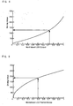
- inverse gamma correction (S19) and quantization may be performed to determine the LED driving value that will be sent to the LED driver circuit 20.
- Figure 8 illustrates an exemplary inverse gamma correction process for the LEDs.
- the quantized driving value is again gamma corrected (S27) to yield the actual LED output.
- the backlight image may now be predicted from the LED image.
- the LED image may be upsampled (S26) to the LCD resolution (m x n) and convolved with the PSF of the diffusion screen (S25) to yield an LED backlight image (LED_BL) 24.
- the LCD transmittance may be calculated (S23) with equation 11 where the HDR input image 10 is divided by LED_BL.
- T LCD x y img x y / bl x y
- inverse gamma correction (S22) may be performed, to correct for the non-linear response of the LCD and the resulting LCD image may be sent to an LCD driver circuit 21.
- Figure 9 shows an exemplary inverse gamma correction curve.
- temporal low-pass filtering (S18) may be used to smooth sudden temporal fluctuations.
- Equation 12 describes an exemplary filtering process.
- LED n i j k up ⁇ f i j + 1 - k up ⁇ LED n - 1 i j _if_f i j > LED n - 1 i j k down ⁇ f i j + 1 - k down ⁇ LED n - 1 i j _else
- k up is typically chosen to be higher than k down to satisfy Equation 6.
- k up may be set to 0.5 and k down may be set to 0.75.
- a method for modifying display backlight target values may comprise the steps of:
- the truncated point spread function (psf 2 ) is a 3x3 kernel represented by: 0 0.6 0 0.6 1 0.6 0 0.6 0
- the diffusion kernel is a 3x3 kernel represented by: 0.25 0 0.25 0 0 0 0.25 0 0.25 0 0.25
- a method for generating a modified LED target value image for a display backlight array may comprise the steps of:
- the point spread function is a 5x7 kernel represented by: 0.04 0.08 0.14 0.19 0.14 0.08 0.04 0.06 0.15 0.4 0.61 0.4 0.15 0.06 0.07 0.2 0.62 1 0.62 0.2 0.07 0.06 0.15 0.4 0.61 0.4 0.15 0.06 0.04 0.08 0.14 0.19 0.14 0.08 0.04
- the method for generating a modified LED target value image may further comprise repeating steps d through h a fixed number of times.
- a method for post-processing backlight image driving values for a display backlight array may comprise the steps of:
- the LED1 image is created by selecting values from said LED1p image and said LEDmax image such that LED1 image values are the greater of the corresponding LEDmax value and the corresponding LED1p value times two.
- the intermediate resolution is a multiple of the resolution of said backlight array.
- the size of said blocks in said SLPF image is determined with the following equation: 1 + k * m / M x n / N wherein k is an overlap factor, M and N are dimensions of the LED backlight array and m and n are the dimensions of an LCD array.
- the method for generating a backlight image may further comprise the steps of:
- the deriving an LED backlight image step comprises:
- performing temporal low-pass filtering on said LED1 image may be done.
- a complete method for generating a backlight image for a display backlight array may comprise the steps of:
- the method further comprising performing temporal low-pass filtering on said BL 1 image.
- said BLo image is created by selecting values from said LED1p image and said LEDmax image such that BLo image values are the greater of the corresponding LEDmax value and the corresponding LEDlp value times two.
- the intermediate resolution is a multiple of the resolution of said backlight array.
- the size of said blocks in said SLPF image is determined with the following equation: 1 + k * m / M x n / N wherein k is an overlap factor, M and N are dimensions of the LED backlight array and m and n are the dimensions of an LCD array.
Landscapes
- Engineering & Computer Science (AREA)
- Physics & Mathematics (AREA)
- Computer Hardware Design (AREA)
- General Physics & Mathematics (AREA)
- Theoretical Computer Science (AREA)
- Chemical & Material Sciences (AREA)
- Crystallography & Structural Chemistry (AREA)
- Liquid Crystal Display Device Control (AREA)
- Control Of Indicators Other Than Cathode Ray Tubes (AREA)
- Liquid Crystal (AREA)
Claims (1)
- Procédé concernant un affichage comprenant une couche à rétroéclairage (2) d'éléments émetteurs de lumière (8) disposés sous forme d'ensemble, une couche de diffusion (4) et un panneau d'affichage (6), ledit procédé étant destiné à produire une image à rétroéclairage pour la couche à rétroéclairage (2), ledit procédé comprenant les étapes :a) de réception d'une image d'entrée (10) comprenant un ensemble de valeurs de pixels représentant une image à une première résolution pour le panneau d'affichage (2) ;b) de filtrage passe-bas (S11) de ladite image d'entrée (10) avec une première matrice représentant une fonction de dispersion de point de la couche de diffusion, pour créer une image de filtrage passe-bas, LPF ;c) d'échantillonnage (S14) de l'image LPF à une résolution intermédiaire, créant ainsi une image intermédiaire (LEDlp), ladite résolution intermédiaire est inférieure à la première résolution ;d) de filtrage passe-bas (S12) de l'image d'entrée (10) avec une deuxième matrice plus petite que la première matrice utilisée pour créer l'image LPF, créant ainsi une deuxième image de filtrage passe-bas, SLPF ;e) de division (S13) de l'image SLPF en blocs, étant précisé que chaque bloc correspond à un élément émetteur de lumière (8) dans la couche à rétroéclairage (2), avec un certain chevauchement entre chaque bloc ;f) de détermination (S15) d'une valeur maximale dans chaque bloc de l'image SLPF, créant ainsi une image maximale (LEDmax) contenant les valeurs maximales de chaque bloc ;g) de création (S16) d'une image combinée (LED1, BL0) comprenant des valeurs de commande cibles basées sur une valeur correspondante provenant de l'image maximale (LEDmax) et/ou sur une valeur correspondante provenant de l'image intermédiaire (LED1p) ;h) de dérivation (S17) d'une image à rétroéclairage (LED) à partir de l'image combinée (LED1) ;i) et de réalisation (S19) d'une correction de gamma inverse sur l'image à rétroéclairage, créant ainsi une image à rétroéclairage à correction de gamma inverse (IGC) pour la couche à rétroéclairage,
caractérisé en ce que la dérivation d'une image à rétroéclairage (S17) comprend les étapes :- de réception de l'image combinée (BL0) contenant les valeurs de commande cibles (40) pour chacun des éléments émetteurs de lumière (8) ;- d'établissement d'une image de valeur de commande initiale (Led1,) comprenant des valeurs de commande virtuelles situées entre les valeurs de commande cibles (40) qui sont positionnées selon ledit ensemble pour les éléments émetteurs de lumière (8), l'image de valeur de commande initiale (Led1) établie en convoluant l'image combinée (BL0) avec un masque (42) comprenant des emplacements des valeurs de commande virtuelles ;- de détermination d'une image à rétroéclairage approchée (bl1) en convoluant (S44) l'image de valeur de commande initiale (Led1) avec une troisième matrice (43), afin d'ajuster les valeurs de commande des éléments émetteurs de lumière (8) pour une émission de lumière accrue ;- de détermination d'une image à rétroéclairage insuffisant (bl2) qui est une différence (S47) entre l'image combinée (BL0)) et ladite image à rétroéclairage approchée (bl1) ;- de création d'une image à rétroéclairage compensé (bl3) en convoluant (S49) l'image à rétroéclairage insuffisant avec une quatrième matrice (50), estimant ainsi la répartition de lumière ; et- de détermination d'une image combinée modifiée (BL1) en ajoutant l'image à rétroéclairage compensé (bl3) à l'image combinée (BL0).
Applications Claiming Priority (2)
| Application Number | Priority Date | Filing Date | Title |
|---|---|---|---|
| US12/177,758 US8531380B2 (en) | 2008-07-22 | 2008-07-22 | Methods and systems for area adaptive backlight management |
| PCT/JP2009/063450 WO2010010963A1 (fr) | 2008-07-22 | 2009-07-22 | Procédés et systèmes pour la gestion adaptative à la zone du rétroéclairage |
Publications (3)
| Publication Number | Publication Date |
|---|---|
| EP2308039A1 EP2308039A1 (fr) | 2011-04-13 |
| EP2308039A4 EP2308039A4 (fr) | 2011-10-19 |
| EP2308039B1 true EP2308039B1 (fr) | 2014-09-24 |
Family
ID=41568173
Family Applications (1)
| Application Number | Title | Priority Date | Filing Date |
|---|---|---|---|
| EP09800474.0A Not-in-force EP2308039B1 (fr) | 2008-07-22 | 2009-07-22 | Procédés et systèmes pour la gestion adaptative à la zone du rétroéclairage |
Country Status (5)
| Country | Link |
|---|---|
| US (1) | US8531380B2 (fr) |
| EP (1) | EP2308039B1 (fr) |
| JP (1) | JP5138809B2 (fr) |
| CN (1) | CN102099849B (fr) |
| WO (1) | WO2010010963A1 (fr) |
Families Citing this family (11)
| Publication number | Priority date | Publication date | Assignee | Title |
|---|---|---|---|---|
| US8890902B2 (en) * | 2008-10-14 | 2014-11-18 | Dolby Laboratories Licensing Corporation | Backlight simulation at reduced resolutions to determine spatial modulation of light for high dynamic range images |
| KR101643203B1 (ko) * | 2009-04-15 | 2016-08-10 | 돌비 레버러토리즈 라이쎈싱 코오포레이션 | 공간 가변 백라이트들을 갖는 박형 디스플레이들 |
| WO2012030526A1 (fr) * | 2010-08-31 | 2012-03-08 | Dolby Laboratories Licensing Corporation | Procédé et appareil d'ajustement de valeurs d'attaque pour dispositifs d'affichage à double modulation |
| JP5197698B2 (ja) * | 2010-09-07 | 2013-05-15 | 株式会社東芝 | 映像表示装置および情報処理装置 |
| WO2013004012A1 (fr) * | 2011-07-06 | 2013-01-10 | Harman International (Shanghai) Management Co., Ltd. | Appareil et procédé de rééchantillonnage et de traitement d'images numériques |
| US9607556B2 (en) | 2012-06-15 | 2017-03-28 | Dolby Laboratories Licensing Corporation | Systems and methods for controlling dual modulation displays |
| EP3008902A1 (fr) * | 2013-06-10 | 2016-04-20 | Thomson Licensing | Procédés de codage et décodage pour adapter la luminance moyenne d'images de gamme dynamique élevée et codeur et décodeur correspondants |
| JP5911518B2 (ja) * | 2014-01-29 | 2016-04-27 | キヤノン株式会社 | 表示装置、表示装置の制御方法、及び、プログラム |
| EP3407604A4 (fr) * | 2016-03-09 | 2019-05-15 | Huawei Technologies Co., Ltd. | Procédé et dispositif pour traiter une image de plage dynamique élevée |
| CN110689497B (zh) * | 2019-09-27 | 2020-05-12 | 信通达智能科技有限公司 | 基于目标识别的数据提取装置及方法 |
| WO2022116002A1 (fr) * | 2020-12-01 | 2022-06-09 | 京东方科技集团股份有限公司 | Procédé et appareil de traitement de données, et appareil d'affichage |
Family Cites Families (32)
| Publication number | Priority date | Publication date | Assignee | Title |
|---|---|---|---|---|
| JP2582644B2 (ja) | 1989-08-10 | 1997-02-19 | 富士写真フイルム株式会社 | 平面型画像表示装置 |
| GB2317290B (en) | 1996-09-11 | 2000-12-06 | Seos Displays Ltd | Image display apparatus |
| JP2001228418A (ja) * | 1999-12-08 | 2001-08-24 | Ricoh Co Ltd | マルチビーム光源ユニットの調整方法、その調整装置、その光源ユニットの組立方法及びそれを用いる画像形成装置 |
| JP4574057B2 (ja) | 2000-05-08 | 2010-11-04 | キヤノン株式会社 | 表示装置 |
| US6864886B1 (en) * | 2000-08-10 | 2005-03-08 | Sportvision, Inc. | Enhancing video using a virtual surface |
| US6891524B2 (en) | 2000-08-14 | 2005-05-10 | Canon Kabushiki Kaisha | Display device with amplification control |
| ES2351206T3 (es) | 2001-02-27 | 2011-02-01 | Dolby Laboratories Licensing Corporation | Dispositivo de visualización de alta relación de contraste dinámico. |
| US7546602B2 (en) * | 2001-07-10 | 2009-06-09 | Microsoft Corporation | Application program interface for network software platform |
| EP1485904B1 (fr) | 2002-03-13 | 2012-08-29 | Dolby Laboratories Licensing Corporation | Dispositifs d'affichage a plage dynamique elevee |
| US8180099B2 (en) * | 2002-07-16 | 2012-05-15 | Trw Limited | Rain detection apparatus and method |
| US7312779B1 (en) * | 2003-09-23 | 2007-12-25 | Northrop Grumman Corporation | Method of color calibration for transmissive displays |
| US7762470B2 (en) * | 2003-11-17 | 2010-07-27 | Dpd Patent Trust Ltd. | RFID token with multiple interface controller |
| JP2005195734A (ja) * | 2004-01-05 | 2005-07-21 | Fujitsu Ltd | 発光制御装置、表示装置、表示制御装置及び表示制御プログラム |
| US20050248553A1 (en) * | 2004-05-04 | 2005-11-10 | Sharp Laboratories Of America, Inc. | Adaptive flicker and motion blur control |
| US8115728B2 (en) * | 2005-03-09 | 2012-02-14 | Sharp Laboratories Of America, Inc. | Image display device with reduced flickering and blur |
| US8026894B2 (en) * | 2004-10-15 | 2011-09-27 | Sharp Laboratories Of America, Inc. | Methods and systems for motion adaptive backlight driving for LCD displays with area adaptive backlight |
| US7525528B2 (en) * | 2004-11-16 | 2009-04-28 | Sharp Laboratories Of America, Inc. | Technique that preserves specular highlights |
| JP5116208B2 (ja) * | 2004-11-19 | 2013-01-09 | 株式会社ジャパンディスプレイイースト | 画像信号表示装置 |
| JP2007012323A (ja) * | 2005-06-28 | 2007-01-18 | Cheil Ind Co Ltd | 面光源装置及び液晶表示装置 |
| US7898520B2 (en) * | 2005-11-30 | 2011-03-01 | 3M Innovative Properties Company | Method and apparatus for backlight simulation |
| JP5176397B2 (ja) * | 2006-06-01 | 2013-04-03 | ソニー株式会社 | 表示装置及びその駆動方法 |
| WO2007143340A2 (fr) * | 2006-06-02 | 2007-12-13 | Clairvoyante, Inc | Système d'affichage à haut contraste dynamique doté d'un éclairage arrière à plusieurs segments |
| US7592996B2 (en) * | 2006-06-02 | 2009-09-22 | Samsung Electronics Co., Ltd. | Multiprimary color display with dynamic gamut mapping |
| JP2008051905A (ja) | 2006-08-22 | 2008-03-06 | Sharp Corp | 液晶表示装置、及びそのバックライト駆動方法 |
| JP4855191B2 (ja) | 2006-09-13 | 2012-01-18 | シャープ株式会社 | 透過型ディスプレイ装置、およびその表示制御方法 |
| US20090243992A1 (en) * | 2006-09-15 | 2009-10-01 | Istvan Gorog | High Efficiency Display Utilizing Simultaneous Color Intelligent Backlighting and Luminescence Controlling Shutters |
| JP2008102379A (ja) * | 2006-10-20 | 2008-05-01 | Hitachi Ltd | 画像表示装置及び画像表示方法 |
| JP4264558B2 (ja) * | 2006-11-10 | 2009-05-20 | ソニー株式会社 | バックライト装置、バックライト駆動方法及びカラー画像表示装置 |
| JP5332172B2 (ja) * | 2006-11-10 | 2013-11-06 | セイコーエプソン株式会社 | 画像表示制御装置 |
| US8941580B2 (en) * | 2006-11-30 | 2015-01-27 | Sharp Laboratories Of America, Inc. | Liquid crystal display with area adaptive backlight |
| DK2240924T3 (en) * | 2008-01-09 | 2016-07-04 | Dolby Laboratories Licensing Corp | REDUCING LCD flicker |
| US8068087B2 (en) * | 2008-05-29 | 2011-11-29 | Sharp Laboratories Of America, Inc. | Methods and systems for reduced flickering and blur |
-
2008
- 2008-07-22 US US12/177,758 patent/US8531380B2/en not_active Expired - Fee Related
-
2009
- 2009-07-22 EP EP09800474.0A patent/EP2308039B1/fr not_active Not-in-force
- 2009-07-22 CN CN200980128332.5A patent/CN102099849B/zh not_active Expired - Fee Related
- 2009-07-22 WO PCT/JP2009/063450 patent/WO2010010963A1/fr not_active Ceased
- 2009-07-22 JP JP2011501839A patent/JP5138809B2/ja not_active Expired - Fee Related
Also Published As
| Publication number | Publication date |
|---|---|
| JP5138809B2 (ja) | 2013-02-06 |
| EP2308039A1 (fr) | 2011-04-13 |
| EP2308039A4 (fr) | 2011-10-19 |
| CN102099849A (zh) | 2011-06-15 |
| US20100020003A1 (en) | 2010-01-28 |
| JP2011528125A (ja) | 2011-11-10 |
| WO2010010963A1 (fr) | 2010-01-28 |
| CN102099849B (zh) | 2014-04-09 |
| US8531380B2 (en) | 2013-09-10 |
Similar Documents
| Publication | Publication Date | Title |
|---|---|---|
| EP2308039B1 (fr) | Procédés et systèmes pour la gestion adaptative à la zone du rétroéclairage | |
| US8026894B2 (en) | Methods and systems for motion adaptive backlight driving for LCD displays with area adaptive backlight | |
| US8314767B2 (en) | Methods and systems for reducing view-angle-induced color shift | |
| EP2409194B1 (fr) | Affichage de rétroéclairage à surface adaptative et procédé comprenant une réduction du calcul et des artefacts de halo | |
| JP4796038B2 (ja) | 画像表示方法 | |
| JP5595516B2 (ja) | 画像データ・ブロックの統計的属性を使ったバックライト制御のための方法およびシステム | |
| KR101333680B1 (ko) | 디스플레이장치 및 그의 밝기 조정방법 | |
| US9076391B2 (en) | High dynamic range display with rear modulator control | |
| EP2612319B1 (fr) | Procédé et appareil d'ajustement de valeurs d'attaque pour dispositifs d'affichage à double modulation | |
| EP2126787B1 (fr) | Afficheurs à modulateurs multiples et procédés associés | |
| KR20120056634A (ko) | 로컬 디밍 방법과 이를 이용한 액정표시장치 | |
| CN100504981C (zh) | 用于减少图像的运动模糊的方法和设备 | |
| KR101389359B1 (ko) | 디스플레이장치 및 그의 밝기 조정방법 | |
| US12198645B2 (en) | Dimming value filtering device, image data processing device and display device for controlling local dimming | |
| HK1184271A (en) | Method and apparatus for adjusting drive values for dual modulation displays | |
| HK1184271B (en) | Method and apparatus for adjusting drive values for dual modulation displays |
Legal Events
| Date | Code | Title | Description |
|---|---|---|---|
| PUAI | Public reference made under article 153(3) epc to a published international application that has entered the european phase |
Free format text: ORIGINAL CODE: 0009012 |
|
| 17P | Request for examination filed |
Effective date: 20110125 |
|
| AK | Designated contracting states |
Kind code of ref document: A1 Designated state(s): AT BE BG CH CY CZ DE DK EE ES FI FR GB GR HR HU IE IS IT LI LT LU LV MC MK MT NL NO PL PT RO SE SI SK SM TR |
|
| AX | Request for extension of the european patent |
Extension state: AL BA RS |
|
| A4 | Supplementary search report drawn up and despatched |
Effective date: 20110920 |
|
| RIC1 | Information provided on ipc code assigned before grant |
Ipc: G09G 3/20 20060101ALI20110914BHEP Ipc: G09G 3/34 20060101ALI20110914BHEP Ipc: G09G 3/36 20060101AFI20110914BHEP |
|
| DAX | Request for extension of the european patent (deleted) | ||
| GRAP | Despatch of communication of intention to grant a patent |
Free format text: ORIGINAL CODE: EPIDOSNIGR1 |
|
| INTG | Intention to grant announced |
Effective date: 20140417 |
|
| GRAS | Grant fee paid |
Free format text: ORIGINAL CODE: EPIDOSNIGR3 |
|
| GRAA | (expected) grant |
Free format text: ORIGINAL CODE: 0009210 |
|
| AK | Designated contracting states |
Kind code of ref document: B1 Designated state(s): AT BE BG CH CY CZ DE DK EE ES FI FR GB GR HR HU IE IS IT LI LT LU LV MC MK MT NL NO PL PT RO SE SI SK SM TR |
|
| REG | Reference to a national code |
Ref country code: GB Ref legal event code: FG4D |
|
| REG | Reference to a national code |
Ref country code: CH Ref legal event code: EP |
|
| REG | Reference to a national code |
Ref country code: AT Ref legal event code: REF Ref document number: 688923 Country of ref document: AT Kind code of ref document: T Effective date: 20141015 |
|
| REG | Reference to a national code |
Ref country code: IE Ref legal event code: FG4D |
|
| REG | Reference to a national code |
Ref country code: DE Ref legal event code: R096 Ref document number: 602009026859 Country of ref document: DE Effective date: 20141106 |
|
| REG | Reference to a national code |
Ref country code: NL Ref legal event code: T3 |
|
| PG25 | Lapsed in a contracting state [announced via postgrant information from national office to epo] |
Ref country code: GR Free format text: LAPSE BECAUSE OF FAILURE TO SUBMIT A TRANSLATION OF THE DESCRIPTION OR TO PAY THE FEE WITHIN THE PRESCRIBED TIME-LIMIT Effective date: 20141225 Ref country code: LT Free format text: LAPSE BECAUSE OF FAILURE TO SUBMIT A TRANSLATION OF THE DESCRIPTION OR TO PAY THE FEE WITHIN THE PRESCRIBED TIME-LIMIT Effective date: 20140924 Ref country code: FI Free format text: LAPSE BECAUSE OF FAILURE TO SUBMIT A TRANSLATION OF THE DESCRIPTION OR TO PAY THE FEE WITHIN THE PRESCRIBED TIME-LIMIT Effective date: 20140924 Ref country code: SE Free format text: LAPSE BECAUSE OF FAILURE TO SUBMIT A TRANSLATION OF THE DESCRIPTION OR TO PAY THE FEE WITHIN THE PRESCRIBED TIME-LIMIT Effective date: 20140924 Ref country code: NO Free format text: LAPSE BECAUSE OF FAILURE TO SUBMIT A TRANSLATION OF THE DESCRIPTION OR TO PAY THE FEE WITHIN THE PRESCRIBED TIME-LIMIT Effective date: 20141224 |
|
| REG | Reference to a national code |
Ref country code: LT Ref legal event code: MG4D |
|
| PG25 | Lapsed in a contracting state [announced via postgrant information from national office to epo] |
Ref country code: CY Free format text: LAPSE BECAUSE OF FAILURE TO SUBMIT A TRANSLATION OF THE DESCRIPTION OR TO PAY THE FEE WITHIN THE PRESCRIBED TIME-LIMIT Effective date: 20140924 Ref country code: HR Free format text: LAPSE BECAUSE OF FAILURE TO SUBMIT A TRANSLATION OF THE DESCRIPTION OR TO PAY THE FEE WITHIN THE PRESCRIBED TIME-LIMIT Effective date: 20140924 Ref country code: LV Free format text: LAPSE BECAUSE OF FAILURE TO SUBMIT A TRANSLATION OF THE DESCRIPTION OR TO PAY THE FEE WITHIN THE PRESCRIBED TIME-LIMIT Effective date: 20140924 |
|
| REG | Reference to a national code |
Ref country code: AT Ref legal event code: MK05 Ref document number: 688923 Country of ref document: AT Kind code of ref document: T Effective date: 20140924 |
|
| PG25 | Lapsed in a contracting state [announced via postgrant information from national office to epo] |
Ref country code: SK Free format text: LAPSE BECAUSE OF FAILURE TO SUBMIT A TRANSLATION OF THE DESCRIPTION OR TO PAY THE FEE WITHIN THE PRESCRIBED TIME-LIMIT Effective date: 20140924 Ref country code: ES Free format text: LAPSE BECAUSE OF FAILURE TO SUBMIT A TRANSLATION OF THE DESCRIPTION OR TO PAY THE FEE WITHIN THE PRESCRIBED TIME-LIMIT Effective date: 20140924 Ref country code: PT Free format text: LAPSE BECAUSE OF FAILURE TO SUBMIT A TRANSLATION OF THE DESCRIPTION OR TO PAY THE FEE WITHIN THE PRESCRIBED TIME-LIMIT Effective date: 20150126 Ref country code: RO Free format text: LAPSE BECAUSE OF FAILURE TO SUBMIT A TRANSLATION OF THE DESCRIPTION OR TO PAY THE FEE WITHIN THE PRESCRIBED TIME-LIMIT Effective date: 20140924 Ref country code: IS Free format text: LAPSE BECAUSE OF FAILURE TO SUBMIT A TRANSLATION OF THE DESCRIPTION OR TO PAY THE FEE WITHIN THE PRESCRIBED TIME-LIMIT Effective date: 20150124 Ref country code: CZ Free format text: LAPSE BECAUSE OF FAILURE TO SUBMIT A TRANSLATION OF THE DESCRIPTION OR TO PAY THE FEE WITHIN THE PRESCRIBED TIME-LIMIT Effective date: 20140924 Ref country code: EE Free format text: LAPSE BECAUSE OF FAILURE TO SUBMIT A TRANSLATION OF THE DESCRIPTION OR TO PAY THE FEE WITHIN THE PRESCRIBED TIME-LIMIT Effective date: 20140924 |
|
| PG25 | Lapsed in a contracting state [announced via postgrant information from national office to epo] |
Ref country code: PL Free format text: LAPSE BECAUSE OF FAILURE TO SUBMIT A TRANSLATION OF THE DESCRIPTION OR TO PAY THE FEE WITHIN THE PRESCRIBED TIME-LIMIT Effective date: 20140924 Ref country code: AT Free format text: LAPSE BECAUSE OF FAILURE TO SUBMIT A TRANSLATION OF THE DESCRIPTION OR TO PAY THE FEE WITHIN THE PRESCRIBED TIME-LIMIT Effective date: 20140924 |
|
| REG | Reference to a national code |
Ref country code: DE Ref legal event code: R097 Ref document number: 602009026859 Country of ref document: DE |
|
| PG25 | Lapsed in a contracting state [announced via postgrant information from national office to epo] |
Ref country code: DK Free format text: LAPSE BECAUSE OF FAILURE TO SUBMIT A TRANSLATION OF THE DESCRIPTION OR TO PAY THE FEE WITHIN THE PRESCRIBED TIME-LIMIT Effective date: 20140924 |
|
| PLBE | No opposition filed within time limit |
Free format text: ORIGINAL CODE: 0009261 |
|
| STAA | Information on the status of an ep patent application or granted ep patent |
Free format text: STATUS: NO OPPOSITION FILED WITHIN TIME LIMIT |
|
| PG25 | Lapsed in a contracting state [announced via postgrant information from national office to epo] |
Ref country code: IT Free format text: LAPSE BECAUSE OF FAILURE TO SUBMIT A TRANSLATION OF THE DESCRIPTION OR TO PAY THE FEE WITHIN THE PRESCRIBED TIME-LIMIT Effective date: 20140924 |
|
| 26N | No opposition filed |
Effective date: 20150625 |
|
| PG25 | Lapsed in a contracting state [announced via postgrant information from national office to epo] |
Ref country code: SI Free format text: LAPSE BECAUSE OF FAILURE TO SUBMIT A TRANSLATION OF THE DESCRIPTION OR TO PAY THE FEE WITHIN THE PRESCRIBED TIME-LIMIT Effective date: 20140924 Ref country code: MC Free format text: LAPSE BECAUSE OF FAILURE TO SUBMIT A TRANSLATION OF THE DESCRIPTION OR TO PAY THE FEE WITHIN THE PRESCRIBED TIME-LIMIT Effective date: 20140924 |
|
| REG | Reference to a national code |
Ref country code: CH Ref legal event code: PL |
|
| GBPC | Gb: european patent ceased through non-payment of renewal fee |
Effective date: 20150722 |
|
| PG25 | Lapsed in a contracting state [announced via postgrant information from national office to epo] |
Ref country code: LU Free format text: LAPSE BECAUSE OF FAILURE TO SUBMIT A TRANSLATION OF THE DESCRIPTION OR TO PAY THE FEE WITHIN THE PRESCRIBED TIME-LIMIT Effective date: 20150722 |
|
| REG | Reference to a national code |
Ref country code: IE Ref legal event code: MM4A |
|
| PG25 | Lapsed in a contracting state [announced via postgrant information from national office to epo] |
Ref country code: LI Free format text: LAPSE BECAUSE OF NON-PAYMENT OF DUE FEES Effective date: 20150731 Ref country code: GB Free format text: LAPSE BECAUSE OF NON-PAYMENT OF DUE FEES Effective date: 20150722 Ref country code: CH Free format text: LAPSE BECAUSE OF NON-PAYMENT OF DUE FEES Effective date: 20150731 |
|
| REG | Reference to a national code |
Ref country code: FR Ref legal event code: ST Effective date: 20160331 |
|
| PG25 | Lapsed in a contracting state [announced via postgrant information from national office to epo] |
Ref country code: FR Free format text: LAPSE BECAUSE OF NON-PAYMENT OF DUE FEES Effective date: 20150731 |
|
| PG25 | Lapsed in a contracting state [announced via postgrant information from national office to epo] |
Ref country code: IE Free format text: LAPSE BECAUSE OF NON-PAYMENT OF DUE FEES Effective date: 20150722 |
|
| PG25 | Lapsed in a contracting state [announced via postgrant information from national office to epo] |
Ref country code: MT Free format text: LAPSE BECAUSE OF FAILURE TO SUBMIT A TRANSLATION OF THE DESCRIPTION OR TO PAY THE FEE WITHIN THE PRESCRIBED TIME-LIMIT Effective date: 20140924 |
|
| PG25 | Lapsed in a contracting state [announced via postgrant information from national office to epo] |
Ref country code: BG Free format text: LAPSE BECAUSE OF FAILURE TO SUBMIT A TRANSLATION OF THE DESCRIPTION OR TO PAY THE FEE WITHIN THE PRESCRIBED TIME-LIMIT Effective date: 20140924 Ref country code: SM Free format text: LAPSE BECAUSE OF FAILURE TO SUBMIT A TRANSLATION OF THE DESCRIPTION OR TO PAY THE FEE WITHIN THE PRESCRIBED TIME-LIMIT Effective date: 20140924 Ref country code: HU Free format text: LAPSE BECAUSE OF FAILURE TO SUBMIT A TRANSLATION OF THE DESCRIPTION OR TO PAY THE FEE WITHIN THE PRESCRIBED TIME-LIMIT; INVALID AB INITIO Effective date: 20090722 |
|
| PG25 | Lapsed in a contracting state [announced via postgrant information from national office to epo] |
Ref country code: TR Free format text: LAPSE BECAUSE OF FAILURE TO SUBMIT A TRANSLATION OF THE DESCRIPTION OR TO PAY THE FEE WITHIN THE PRESCRIBED TIME-LIMIT Effective date: 20140924 |
|
| PG25 | Lapsed in a contracting state [announced via postgrant information from national office to epo] |
Ref country code: BE Free format text: LAPSE BECAUSE OF FAILURE TO SUBMIT A TRANSLATION OF THE DESCRIPTION OR TO PAY THE FEE WITHIN THE PRESCRIBED TIME-LIMIT Effective date: 20140924 |
|
| PG25 | Lapsed in a contracting state [announced via postgrant information from national office to epo] |
Ref country code: MK Free format text: LAPSE BECAUSE OF FAILURE TO SUBMIT A TRANSLATION OF THE DESCRIPTION OR TO PAY THE FEE WITHIN THE PRESCRIBED TIME-LIMIT Effective date: 20140924 |
|
| PGFP | Annual fee paid to national office [announced via postgrant information from national office to epo] |
Ref country code: NL Payment date: 20190719 Year of fee payment: 11 |
|
| PGFP | Annual fee paid to national office [announced via postgrant information from national office to epo] |
Ref country code: DE Payment date: 20200721 Year of fee payment: 12 |
|
| REG | Reference to a national code |
Ref country code: NL Ref legal event code: MM Effective date: 20200801 |
|
| PG25 | Lapsed in a contracting state [announced via postgrant information from national office to epo] |
Ref country code: NL Free format text: LAPSE BECAUSE OF NON-PAYMENT OF DUE FEES Effective date: 20200801 |
|
| REG | Reference to a national code |
Ref country code: DE Ref legal event code: R119 Ref document number: 602009026859 Country of ref document: DE |
|
| PG25 | Lapsed in a contracting state [announced via postgrant information from national office to epo] |
Ref country code: DE Free format text: LAPSE BECAUSE OF NON-PAYMENT OF DUE FEES Effective date: 20220201 |