EP2308129B1 - Einrichtung zum halten, unterbringen und kühlen von strahlungsmodulen einer antenne, insbesondere gruppenantenne - Google Patents
Einrichtung zum halten, unterbringen und kühlen von strahlungsmodulen einer antenne, insbesondere gruppenantenne Download PDFInfo
- Publication number
- EP2308129B1 EP2308129B1 EP08808199A EP08808199A EP2308129B1 EP 2308129 B1 EP2308129 B1 EP 2308129B1 EP 08808199 A EP08808199 A EP 08808199A EP 08808199 A EP08808199 A EP 08808199A EP 2308129 B1 EP2308129 B1 EP 2308129B1
- Authority
- EP
- European Patent Office
- Prior art keywords
- radiant
- modules
- plate
- antenna
- cooling
- Prior art date
- Legal status (The legal status is an assumption and is not a legal conclusion. Google has not performed a legal analysis and makes no representation as to the accuracy of the status listed.)
- Active
Links
Images



Classifications
-
- H—ELECTRICITY
- H01—ELECTRIC ELEMENTS
- H01Q—ANTENNAS, i.e. RADIO AERIALS
- H01Q1/00—Details of, or arrangements associated with, antennas
- H01Q1/02—Arrangements for de-icing; Arrangements for drying-out ; Arrangements for cooling; Arrangements for preventing corrosion
-
- H—ELECTRICITY
- H01—ELECTRIC ELEMENTS
- H01Q—ANTENNAS, i.e. RADIO AERIALS
- H01Q21/00—Antenna arrays or systems
- H01Q21/0006—Particular feeding systems
- H01Q21/0025—Modular arrays
-
- H—ELECTRICITY
- H01—ELECTRIC ELEMENTS
- H01Q—ANTENNAS, i.e. RADIO AERIALS
- H01Q21/00—Antenna arrays or systems
- H01Q21/0087—Apparatus or processes specially adapted for manufacturing antenna arrays
Definitions
- the present invention relates to a device for supporting, housing and cooling radiant modules of an antenna, particularly an array antenna.
- the invention concerns a device of the above kind, particularly studied and realized for permitting a high "packing" of radiant modules and at the same time easing access to the same thus permitting an easy maintenance.
- radar array antenna technology is diffused in different sectors of tele-detection.
- Array antennas are comprised of an assembly of radiant modules, which are generally all the same, provided along a line or a plane, equally-oriented and each supplied with different amplitudes and phases.
- Advantage of using the above technology is that of obtaining a configurable radiation diagram, varying amplitude and phases of signals supplying single modules comprising the antenna. Moreover, it is possible designing an array antenna in order to obtain polar diagrams with main lobes and zeros in the wished positions.
- Programmable array antennas exist, able modifying their radiation diagram varying supply of radiant modules comprising the same.
- array antennas are diffused in spatial applications, in radars and all applications wherein it is necessary a high emission of power.
- Array antennas employed for radar permit reaching maximum operative efficiency when radiant modules are as closer as possible.
- radiant modules tend to dissipate much heat and difficulties for cooling would arise installing them very close each other.
- support devices also known as "cold plate” are presently employed in this sector permitting both housing and cooling radiant modules.
- Said devices have a substantially planar structure permitting housing a plurality of radiant modules thus creating a line of the array antenna.
- a plurality of said devices creates a planar array antenna. Each one of them is fixed to a support structure. Placing said devices one above the other. Channels are provided within said devices, wherein a pump makes the cooling liquid flowing.
- Main limit to the housing of said radiant modules is due to the need of permitting a quick replacement of one or more radiant modules in case of failure.
- US patent n° 5,431,582 concerns an apparatus for housing radiant modules for radar antennas.
- Each module comprises a tubular assembly at one end of a helicoidal groove, and on the other end means suitable to permit coupling of a tool.
- Said apparatus also comprises a pin, which is integral with the cooling element, on which said tubular element can be assembled, so that, following rotation of the latter by said tool, said pin enters within the helicoidal groove. It implies a linear translation of module into two distinct orthogonal directions, so as to maintain the module within the housing.
- Said system further comprises an inlet path for the cooling fluid and an outlet path.
- System can permit introduction and withdrawal of microwave modules (preferably with a matrix arrangement) into suitable housing seats independently each other. Solution also permits sending cooling liquid in an optimum way.
- US patent 6,469,671 B1 concerns an array antenna comprising a plurality of radiofrequency radiant modules thermally coupled with a plane cooling element (cold plate), to which a support structure is coupled, in said support structure being possible inserting radiofrequency radiant modules, parallel each other.
- support structure permits containing each module within housing after its insertion and sliding within the same.
- said patent does not describe a system for exerting a pressure on module in order to optimize module/cold plate thermal coupling.
- modules do not have a coupling with a cooling element by said surfaces.
- Said network is comprised of a plurality of circuits, preferably micro strip circuits, apt to distributing radiofrequency signal to the different radiant modules and it is known that it is very delicate. In fact, damaging of said network often occurs mainly during the following maintenance steps of the radiant modules, during which the whole support - housing - cooling device must be mounted again.
- Further examples of prior art devices are known from US 6,611,430 B1 and JP 2006278430 .
- It also object of the present invention that of permitting an assembling of modules within a support, housing and cooling device maintaining a preset and uniform pressure on a surface (preferably, but not only identified by the lower one) of the same transceiving module for an efficient cooling.
- said device can comprise a plurality of projecting guides, both on said upper surface and on said lower surface of the plate, so as to permit realization of said housing seats of said radiant modules on both said plate surfaces.
- said projecting guide can have a "T" shaped cross section.
- said one or more through holes of each one of said projecting guides can be obtained in the projecting portion of the same.
- said elastic means can be comprised of a spring.
- said device can comprise a containment structure, fixed on the side opposite to the side where said radiant modules are housed, apt to house and insulate two networks, one network for distribution of radiofrequency signal to radiant modules, and a network for distribution of digital signals and of electric supply to radiant modules.
- said processing circuit for signal can be placed in a seat of said plate and it is electrically connected with said radiofrequency signal distribution network, and with said digital signal distribution network and to electric supplies by suitable connectors.
- each one of said radiant modules can comprise an envelope, within which a signal processing unit is provided, having a front end and a rear end and a pair of lateral fins suitable to enter within said projecting guide and on which said pressing means exert a pressure, a portion of wave guide or radiant mouth, fixed to said front end of said envelope, apt to receiving and transmitting radiofrequency signals, and a connector placed in correspondence of said rear end of said envelope, that can be connected with said radiofrequency signal distribution network.
- said device can comprise, for each radiant module, a connector, placed on the bottom of each seat coupable with the corresponding connector of the radiant module housed within said seat; a space, in correspondence of each seat and co-planar with respect to the same; and a radiofrequency cable, placed within said space, the ends of which are connected with said connector and with said radiofrequency signal distribution network.
- said radiant modules can permit receiving and transmitting, event at the same time radiofrequency signals.
- said plate can comprise one or more inner channels, for flow of a cooling liquid, and inlet and outlet openings for said cooling liquid.
- said device can comprise a front protection cover provided on said radiant guides.
- said plate can comprise flanges for fixing with said antenna support means.
- an array antenna comprising a.support structure; a plurality of support, housing and cooling devices for radiant modules, each one coupable with said antenna support structure by said flanges so as to overlap each other, the radiant modules thus realizing a matrix radiant assembly.
- said antenna can comprise cooling fluid pumping means coupled with said openings of each device.
- a device 1 for supporting, housing and cooling radiant modules 2 of a planar type array antenna (not shown).
- Device 1 comprises a plate 3 (cold plate) for housing and cooling said radiant modules 2, contacting its upper and lower surfaces, so that the assembly is along two juxtaposed parallel lines.
- Openings 4', 4" are present at the ends of said plate 3 for inlet and outlet of a cooling liquid. Said liquid is circulated by a pumping system (not shown in the figures) within inner channels (not visible in these figures) toward said plate 3.
- a plurality of projecting guides 5, parallel each other and with a "T" shape cross section is present on said upper and lower surface of said plate 3. Said projecting guides in pairs, along with the surface of the plate 3 on which they are provided, individuate a housing 6 within which it is possible introducing a single radiant module 2.
- Each radiant module 2 comprises a signal processing portion within an envelope 2', generally comprised of metal, and a radiant guide 2", i.e. an open wave guide apt to irradiating the signal processed by said processing portion.
- a radiant guide 2 i.e. an open wave guide apt to irradiating the signal processed by said processing portion.
- said envelope 2' comprises fins (not visible in the present figure) suitable to enter under said projecting guides 5.
- pressing means 7 are provided, integrated in said projecting guides 5, permitting exerting a pressure on said envelope 2' sides, and particularly on said fins.
- Each radiant module 2, once introduced within a housing 6, is longitudinally blocked on said plate 3 by screws 8 fixing two radiant guides 2" of two adjacent radiant modules 2, screwing within a threaded hole 9 obtained on said projecting guides 5.
- Said plate 3 also houses a signal processing circuit 10 necessary for control logic of said signal and a radiofrequency signal distribution network 11 for distribution to said radiant modules 2, known as Horizontal Beam Forming Network.
- Each seat 6 is provided with a connector 6' on the bottom vertical wall that can be coupled with a corresponding connector 2" of the radiant module housed within the same.
- Radiofrequency signal on said connector 6' is brought by a radiofrequency cable 12, placed within a space 13 corresponding to each seat 6, connected to the radiofrequency signal distribution network 11.
- said device 1 also comprises flanges 14 for fixing to a support structure mounted within array antenna.
- a typical planar array antenna is comprised of a plurality of said devices 1, projecting juxtaposed each other, so as to realize a radiant plane.
- Structure of device 1 described in the above permits a quick replacement even of a single failing radiant module 2.
- a technician must only remove screws 8 fixing radiant guide 2" of the module 2 to be replaced, extract said radiant module 2 manually or acting on said radiant guide 2" by a suitable tool and inserting a new radiant module 2 between the projecting guides 5.
- each one of said screws 8 blocks a pair of adjacent modules 2 in position, i.e. is inserted through two adjacent radiant guides 2".
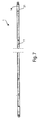
- FIGs 4 - 8 show section views of device 1, wherein it is possible observing pressing means 7.
- Each projecting guide 5 has one or more through holes 18, which are threaded inside and with their axis substantially perpendicular to the surface of said plate 3 (cold plate).
- Pressing means 7 comprised of a dowel 15, within which a spring 16 and a sphere 17 are present.
- Each one of said dowels 15 is inserted and screwed within a through hole 18.
- Spheres 17 of said dowels 15 exert a constant pressure on the lateral surface of said radiant module 2, and particularly of envelope 2', said pressure being easily adjustable by screwing of each dowel 15 within the hole 18. This permits exerting a higher pressure on the front portion of envelope 2' rather than on the rear portion of envelope 2', or vice versa, in order to permit a better dissipation of heat generated.
- each envelope 2' is laterally provided with a fin 19 on which spheres 17 exert a pressure.
- spheres 17, rotating permit an easy sliding of the same module.
- total assembly comprised of plate 3, radiant modules 2 and radiofrequency signal distribution network 11 realized by device 1 is really compact and permits a high packing of radiant modules 2.
- a protection cover is mounted on radiant guides.
- An advantage of the present invention is that of permitting a reduction of time necessary to replace radiant modules, permitting few and simple mechanical operations, such as particularly, dismounting of the sole antenna front cover. This permits ensuring to the active antenna, of which the different support, housing and cooling devices according to the invention are integral part, full performance conditions, easily and quickly replacing failing transmitting modules.
Landscapes
- Engineering & Computer Science (AREA)
- Manufacturing & Machinery (AREA)
- Variable-Direction Aerials And Aerial Arrays (AREA)
Claims (15)
- Vorrichtung (1) zum Halten, Beherbergen und Kühlen von Strahlungsmodulen (2) einer Antenne, umfassend eine Platte (3) zum Kühlen der Strahlungsmodule (2), befestigbar an Mittel zum Halten der Antenne, wobei die Platte (3) eine obere Fläche und eine untere Fläche aufweist;
eine Vielzahl von Vorsprungsführungen (5), bereitgestellt an zumindest einer der Flächen der Platte (3), so dass jedes Paar der Vorsprungsführungen (5) benachbart zu der Fläche, an der Sie bereitgestellt sind, Beherbergungssitze (6) realisieren, wobei in jedem der Beherbergungssitze eines der Strahlungsmodule (2) eingefügt wird;
Drückmittel (7, 15, 16, 17), integriert mit den Vorsprungsführungen (5), geeignet, einen Druck auf die Strahlungsmodule (2) auszuüben, um eine im Wesentlichen einheitliche Kopplung zu erhalten zwischen jedem von diesen und der Fläche der Platte (3), an der die Vorsprungsführungen (5) bereitgestellt sind;
dadurch gekennzeichnet, dass
jede der Vorsprungsführungen (5) eine Vielzahl von Durchgangslöchern (18) aufweist, entlang deren Längsdimension, worin die Drückmittel (7, 15, 16, 17) platziert sind, wobei die Durchgangslöcher (18) ihre Achse im Wesentlichen rechtwinklig zu der Fläche der Platte (3) haben,
jedes der Durchgangslöcher (18) innenseitig mit einem Gewinde versehen ist und die Drückmittel (7) einen Zapfen (15) bereitstellen, der in eines der Durchgangslöcher (18) geschraubt werden kann, wobei der Zapfen (15) innenseitig elastische Mittel (16) und eine Sphäre (17) umfasst, an der die elastischen Mittel (16) wirken, wobei die Sphäre (17) ein Gleiten des Strahlungsmoduls (2) während dessen Einfügens in den Sitz (6) erlaubt und einen einheitlichen und einstellbaren Druck auf dasselbe ausübt. - Vorrichtung (1) gemäß Anspruch 1, dadurch gekennzeichnet, dass sie eine Vielzahl von Vorsprungsführungen (5) umfasst, beide an der oberen Fläche und an der unteren Fläche der Platte (3), um die Realisierung der Beherbergungssitze (6) der Strahlungsmodule (2) an beiden Flächen der Platte (3) zu ermöglichen.
- Vorrichtung (1) gemäß einem der vorhergehenden Ansprüche, dadurch gekennzeichnet, dass die Vorsprungsführungen (5) einen "T"-förmigen Querschnitt aufweisen.
- Vorrichtung (1) gemäß einem der vorhergehenden Ansprüche, dadurch gekennzeichnet, dass das eine oder die mehreren Durchgangslöcher (18) von jeder der Vorsprungsführungen (5) dargestellt wird in dem Vorsprungsabschnitt derselben.
- Vorrichtung (1) gemäß einem der vorhergehenden Ansprüche, dadurch gekennzeichnet, dass die elastischen Mittel aus einer Feder (16) bestehen.
- Vorrichtung (1) gemäß einem der vorhergehenden Ansprüche, dadurch gekennzeichnet, dass sie eine Einschließungsstruktur (21) umfasst, fixiert an der Seite gegenüberstehend der Seite, wo die Strahlungsmodule (2) beherbergt sind, geeignet, um ein Netzwerk (11) zur Radiofrequenzsignalverteilung an Strahlungsmodule (2) zu beherbergen und zu isolieren, und ein Netzwerk zur Verteilung von digitalen Signalen und von Elektrozufuhr an Strahlungsmodule (2).
- Vorrichtung (1) gemäß einem der vorhergehenden Ansprüche, dadurch gekennzeichnet, dass eine Verarbeitungsschaltung für Signale (10) platziert ist in einem Sitz der Platte (3) und diese elektrisch verbunden ist mit dem Radiofrequenzsignalverteilungsnetzwerk (11) und mit dem Digitalsignalverteilungsnetzwerk und mit Elektrozufuhren mittels geeigneter Verbindungen.
- Vorrichtung (1) gemäß einem der vorhergehenden Ansprüche, dadurch gekennzeichnet, dass jedes der Strahlungsmodule (2) umfasst
eine Hülle (2'), in der eine Signalverarbeitungseinheit bereitgestellt ist, aufweisend ein vorderes Ende und ein hinteres Ende und ein paar lateraler Rippen (19), geeignet, um in die Vorsprungsführung (5) einzutreten und auf die die Drückmittel (7) Druck ausüben,
einen Abschnitt einer Wellenführung oder eines Strahlungsmunds (2"), fixiert an dem vorderen Ende der Hülle (2'), geeignet, um Radiofrequenzsignale zu empfangen und zu übermitteln, und
einen Verbinder (2"'), platziert in Übereinstimmung mit dem hinteren Ende der Hülle (2'), verbindbar mit dem Radiofrequenzsignalverteilungsnetzwerk (11). - Vorrichtung (1) gemäß Anspruch 8, dadurch gekennzeichnet, dass sie für jedes Strahlungsmodul (2) umfasst
einen Verbinder (6'), platziert an dem Boden jedes Sitzes (6), gekoppelt mit dem entsprechenden Verbinder (2"') des Strahlungsmoduls (2), beherbergt in dem Sitz (6);
einen Raum (13), in Übereinstimmung mit jedem Sitz (6) und ko-planar in Bezug auf denselben; und
ein Radiofrequenzkabel (12), platziert in dem Raum (13), wobei die Enden davon verbunden sind mit dem Verbinder (6') und mit dem Radiofrequenzsignalverteilungsnetzwerk (11). - Vorrichtung (1) gemäß einem der vorhergehenden Ansprüche, dadurch gekennzeichnet, dass die Strahlungsmodule (2) ein Empfangen und ein Übermitteln von Radiofrequenzsignalen erlauben.
- Vorrichtung (1) gemäß einem der vorhergehenden Ansprüche, dadurch gekennzeichnet, dass die Platte (3) umfasst
einen oder mehrere innere Kanäle (20) zum Fließen einer Kühlflüssigkeit und
Einlass- und Auslassöffnungen (4', 4") für die Kühlflüssigkeit. - Vorrichtung (1) gemäß einem der vorhergehenden Ansprüche, dadurch gekennzeichnet, dass sie eine vordere Schutzabdeckung umfasst, bereitgestellt an den Strahlungsführungen (2").
- Vorrichtung (1) gemäß einem der vorhergehenden Ansprüche, dadurch gekennzeichnet, dass die Platte (3) Flansche (14) zum Fixieren mit den Antennenhaltemitteln umfasst.
- Array-Antenne, umfassend
eine Haltestruktur;
eine Vielzahl von Halte-, Beherbergungs- und Kühlvorrichtungen (1) für Strahlungsmodule (2), wie definiert in den Ansprüchen 1-13, jedes gekoppelt mit der Antennenhaltestruktur durch die Flansche (14), um einander zu überlappen, wobei die Strahlungsmodule (2) somit einen Matrixstrahlungsaufbau realisieren. - Array-Antenne gemäß Anspruch 14, dadurch gekennzeichnet, dass sie Kühlflüssigkeitspumpmittel umfasst, gekoppelt mit den Öffnungen (4', 4") jeder Vorrichtung (1).
Applications Claiming Priority (1)
| Application Number | Priority Date | Filing Date | Title |
|---|---|---|---|
| PCT/IT2008/000485 WO2010007637A1 (en) | 2008-07-18 | 2008-07-18 | Device for supporting, housing and cooling radiant modules of an antenna, particularly array antenna |
Publications (2)
| Publication Number | Publication Date |
|---|---|
| EP2308129A1 EP2308129A1 (de) | 2011-04-13 |
| EP2308129B1 true EP2308129B1 (de) | 2012-02-22 |
Family
ID=40627607
Family Applications (1)
| Application Number | Title | Priority Date | Filing Date |
|---|---|---|---|
| EP08808199A Active EP2308129B1 (de) | 2008-07-18 | 2008-07-18 | Einrichtung zum halten, unterbringen und kühlen von strahlungsmodulen einer antenne, insbesondere gruppenantenne |
Country Status (6)
| Country | Link |
|---|---|
| US (1) | US8837148B2 (de) |
| EP (1) | EP2308129B1 (de) |
| AT (1) | ATE546853T1 (de) |
| BR (1) | BRPI0822942B1 (de) |
| ES (1) | ES2381797T3 (de) |
| WO (1) | WO2010007637A1 (de) |
Cited By (2)
| Publication number | Priority date | Publication date | Assignee | Title |
|---|---|---|---|---|
| US20110279343A1 (en) * | 2008-07-18 | 2011-11-17 | Selex Sistemi Integrati S.P.A. | Device for supporting, housing and cooling radiant modules of an antenna, particularly array antenna |
| US9577317B2 (en) | 2013-02-22 | 2017-02-21 | Samsung Electronics Co., Ltd. | Heat radiation antenna device, portable terminal and battery cover therewith, and method for manufacturing the battery cover |
Families Citing this family (12)
| Publication number | Priority date | Publication date | Assignee | Title |
|---|---|---|---|---|
| GB2474923B (en) | 2008-07-18 | 2011-11-16 | Phasor Solutions Ltd | A phased array antenna and a method of operating a phased array antenna |
| GB2491804B (en) | 2011-05-11 | 2018-01-17 | Syrinix Ltd | Pipeline fault detection system and monitor unit |
| GB201215114D0 (en) | 2012-08-24 | 2012-10-10 | Phasor Solutions Ltd | Improvements in or relating to the processing of noisy analogue signals |
| GB2513094B (en) | 2013-02-14 | 2019-03-13 | Syrinix Ltd | Pipeline pressure transient event monitoring unit and method |
| IL228426B (en) * | 2013-09-15 | 2018-10-31 | Elta Systems Ltd | Temperature control for show array antenna |
| GB201403507D0 (en) | 2014-02-27 | 2014-04-16 | Phasor Solutions Ltd | Apparatus comprising an antenna array |
| DE102018102765A1 (de) * | 2018-02-07 | 2019-08-08 | Airbus Operations Gmbh | Antennenanordnung für ein Flugzeug |
| RU185058U1 (ru) * | 2018-08-16 | 2018-11-19 | Акционерное общество "Научно-производственная фирма "Микран" | Пост антенный |
| GB2597763A (en) | 2020-08-04 | 2022-02-09 | Syrinix Ltd | Transient pressure event detection system and method |
| US11411295B2 (en) * | 2020-09-18 | 2022-08-09 | Raytheon Company | Antenna sub-array blocks having heat dissipation |
| CN115764324A (zh) * | 2022-10-19 | 2023-03-07 | 中国电子科技集团公司第三十八研究所 | 超多通道收发天线阵面成形工艺 |
| CN115986365A (zh) * | 2022-11-18 | 2023-04-18 | 中国船舶重工集团公司第七二四研究所 | 一种集成式轻量化阵列行馈天线骨架 |
Family Cites Families (12)
| Publication number | Priority date | Publication date | Assignee | Title |
|---|---|---|---|---|
| US4870375A (en) * | 1987-11-27 | 1989-09-26 | General Electric Company | Disconnectable microstrip to stripline transition |
| DE4338836A1 (de) * | 1993-11-13 | 1995-05-18 | Deutsche Aerospace | Anordnung zur Aufnahme von mehreren Sende- und/oder Empfangsmoduln |
| US5431582A (en) * | 1994-03-28 | 1995-07-11 | Raytheon Company | Module retention apparatus |
| US5457607A (en) * | 1994-03-28 | 1995-10-10 | Raytheon Company | Unified module housing |
| US6469671B1 (en) * | 2001-07-13 | 2002-10-22 | Lockheed Martin Corporation | Low-temperature-difference TR module mounting, and antenna array using such mounting |
| US6611430B1 (en) * | 2002-09-04 | 2003-08-26 | Northrop Grumman Corporation | Miniature self-locking, spring action, microwave module retainer |
| US6952345B2 (en) * | 2003-10-31 | 2005-10-04 | Raytheon Company | Method and apparatus for cooling heat-generating structure |
| JP2006278430A (ja) * | 2005-03-28 | 2006-10-12 | Mitsubishi Electric Corp | 送受信モジュール |
| US7548424B2 (en) * | 2007-03-12 | 2009-06-16 | Raytheon Company | Distributed transmit/receive integrated microwave module chip level cooling system |
| US8837148B2 (en) * | 2008-07-18 | 2014-09-16 | Selex Sistemi Integrati S.p.A. P.A. | Device for supporting, housing and cooling radiant modules of an antenna, particularly array antenna |
| WO2011059582A1 (en) * | 2009-11-12 | 2011-05-19 | Sensis Corporation | Light-weight, air-cooled transmit/receive unit and active phased array including same |
| EP2622686B1 (de) * | 2010-10-01 | 2018-03-21 | Saab AB | Montagesystem für sender-empfänger-module |
-
2008
- 2008-07-18 US US12/737,286 patent/US8837148B2/en active Active
- 2008-07-18 AT AT08808199T patent/ATE546853T1/de active
- 2008-07-18 BR BRPI0822942-2A patent/BRPI0822942B1/pt active IP Right Grant
- 2008-07-18 WO PCT/IT2008/000485 patent/WO2010007637A1/en not_active Ceased
- 2008-07-18 EP EP08808199A patent/EP2308129B1/de active Active
- 2008-07-18 ES ES08808199T patent/ES2381797T3/es active Active
Cited By (3)
| Publication number | Priority date | Publication date | Assignee | Title |
|---|---|---|---|---|
| US20110279343A1 (en) * | 2008-07-18 | 2011-11-17 | Selex Sistemi Integrati S.P.A. | Device for supporting, housing and cooling radiant modules of an antenna, particularly array antenna |
| US8837148B2 (en) * | 2008-07-18 | 2014-09-16 | Selex Sistemi Integrati S.p.A. P.A. | Device for supporting, housing and cooling radiant modules of an antenna, particularly array antenna |
| US9577317B2 (en) | 2013-02-22 | 2017-02-21 | Samsung Electronics Co., Ltd. | Heat radiation antenna device, portable terminal and battery cover therewith, and method for manufacturing the battery cover |
Also Published As
| Publication number | Publication date |
|---|---|
| WO2010007637A1 (en) | 2010-01-21 |
| EP2308129A1 (de) | 2011-04-13 |
| BRPI0822942B1 (pt) | 2021-09-14 |
| ATE546853T1 (de) | 2012-03-15 |
| ES2381797T3 (es) | 2012-05-31 |
| US20110279343A1 (en) | 2011-11-17 |
| US8837148B2 (en) | 2014-09-16 |
| BRPI0822942A2 (pt) | 2018-12-26 |
Similar Documents
| Publication | Publication Date | Title |
|---|---|---|
| EP2308129B1 (de) | Einrichtung zum halten, unterbringen und kühlen von strahlungsmodulen einer antenne, insbesondere gruppenantenne | |
| EP0390053B1 (de) | Zwischenstruktur zur Wärmeableitung vom elektrischen Modul | |
| US6393853B1 (en) | Liquid cooling of removable electronic modules based on low pressure applying biasing mechanisms | |
| CN110600851B (zh) | 一种相控阵天线转接冷却结构 | |
| US20230345668A1 (en) | Receptacle with connectable spring finger for multipoint contact conduction cooling | |
| US6469671B1 (en) | Low-temperature-difference TR module mounting, and antenna array using such mounting | |
| EP3675615B1 (de) | Flexible kaltplatte mit flüssigkeitsverteilungsmechanismus | |
| US20150077937A1 (en) | Apparatus for cooling board mounted optical modules | |
| EP3629691A1 (de) | Flüssigkeitskammergehäuse | |
| US20160093996A1 (en) | Receptacle assembly with heat extraction from a pluggable module | |
| JP7418572B2 (ja) | ノズル配列および冷却モジュール | |
| CN111289877A (zh) | 一种老化测试设备 | |
| CN111726963B (zh) | 用于改善动态网络连接的热性能的装置 | |
| US12063755B2 (en) | Latch mechanism and server assembly and rack-mount server system employing same | |
| US20200301488A1 (en) | Dissipating interconnection module for m.2 form factor expansion card | |
| US12322904B2 (en) | Receptacle assembly having a module orientation feature for pluggable module | |
| CN112020280A (zh) | 一种适用于相控阵雷达的阵面电源模块 | |
| US11417451B2 (en) | Magnetic blocks for thermally coupling cooling component and heat spreader | |
| CN116417784A (zh) | 一种共形相控阵数据链系统 | |
| CN216354815U (zh) | 一种多角度辐射式相控阵天线 | |
| CN117766973B (zh) | 一种基于有源相控阵天线散热的微流道散热器 | |
| JP3942849B2 (ja) | アレイアンテナの冷却構造 | |
| CN223598186U (zh) | 计算设备 | |
| US11096302B2 (en) | Server | |
| US20240431070A1 (en) | Server cooling with immersed heat sink |
Legal Events
| Date | Code | Title | Description |
|---|---|---|---|
| PUAI | Public reference made under article 153(3) epc to a published international application that has entered the european phase |
Free format text: ORIGINAL CODE: 0009012 |
|
| 17P | Request for examination filed |
Effective date: 20110128 |
|
| AK | Designated contracting states |
Kind code of ref document: A1 Designated state(s): AT BE BG CH CY CZ DE DK EE ES FI FR GB GR HR HU IE IS IT LI LT LU LV MC MT NL NO PL PT RO SE SI SK TR |
|
| AX | Request for extension of the european patent |
Extension state: AL BA MK RS |
|
| GRAP | Despatch of communication of intention to grant a patent |
Free format text: ORIGINAL CODE: EPIDOSNIGR1 |
|
| DAX | Request for extension of the european patent (deleted) | ||
| GRAS | Grant fee paid |
Free format text: ORIGINAL CODE: EPIDOSNIGR3 |
|
| GRAA | (expected) grant |
Free format text: ORIGINAL CODE: 0009210 |
|
| AK | Designated contracting states |
Kind code of ref document: B1 Designated state(s): AT BE BG CH CY CZ DE DK EE ES FI FR GB GR HR HU IE IS IT LI LT LU LV MC MT NL NO PL PT RO SE SI SK TR |
|
| REG | Reference to a national code |
Ref country code: GB Ref legal event code: FG4D |
|
| REG | Reference to a national code |
Ref country code: CH Ref legal event code: EP |
|
| REG | Reference to a national code |
Ref country code: AT Ref legal event code: REF Ref document number: 546853 Country of ref document: AT Kind code of ref document: T Effective date: 20120315 |
|
| REG | Reference to a national code |
Ref country code: IE Ref legal event code: FG4D |
|
| REG | Reference to a national code |
Ref country code: DE Ref legal event code: R096 Ref document number: 602008013644 Country of ref document: DE Effective date: 20120419 |
|
| REG | Reference to a national code |
Ref country code: SE Ref legal event code: TRGR |
|
| REG | Reference to a national code |
Ref country code: NL Ref legal event code: T3 |
|
| REG | Reference to a national code |
Ref country code: ES Ref legal event code: FG2A Ref document number: 2381797 Country of ref document: ES Kind code of ref document: T3 Effective date: 20120531 |
|
| LTIE | Lt: invalidation of european patent or patent extension |
Effective date: 20120222 |
|
| PG25 | Lapsed in a contracting state [announced via postgrant information from national office to epo] |
Ref country code: HR Free format text: LAPSE BECAUSE OF FAILURE TO SUBMIT A TRANSLATION OF THE DESCRIPTION OR TO PAY THE FEE WITHIN THE PRESCRIBED TIME-LIMIT Effective date: 20120222 Ref country code: IS Free format text: LAPSE BECAUSE OF FAILURE TO SUBMIT A TRANSLATION OF THE DESCRIPTION OR TO PAY THE FEE WITHIN THE PRESCRIBED TIME-LIMIT Effective date: 20120622 Ref country code: LT Free format text: LAPSE BECAUSE OF FAILURE TO SUBMIT A TRANSLATION OF THE DESCRIPTION OR TO PAY THE FEE WITHIN THE PRESCRIBED TIME-LIMIT Effective date: 20120222 Ref country code: NO Free format text: LAPSE BECAUSE OF FAILURE TO SUBMIT A TRANSLATION OF THE DESCRIPTION OR TO PAY THE FEE WITHIN THE PRESCRIBED TIME-LIMIT Effective date: 20120522 |
|
| PG25 | Lapsed in a contracting state [announced via postgrant information from national office to epo] |
Ref country code: GR Free format text: LAPSE BECAUSE OF FAILURE TO SUBMIT A TRANSLATION OF THE DESCRIPTION OR TO PAY THE FEE WITHIN THE PRESCRIBED TIME-LIMIT Effective date: 20120523 Ref country code: LV Free format text: LAPSE BECAUSE OF FAILURE TO SUBMIT A TRANSLATION OF THE DESCRIPTION OR TO PAY THE FEE WITHIN THE PRESCRIBED TIME-LIMIT Effective date: 20120222 Ref country code: BE Free format text: LAPSE BECAUSE OF FAILURE TO SUBMIT A TRANSLATION OF THE DESCRIPTION OR TO PAY THE FEE WITHIN THE PRESCRIBED TIME-LIMIT Effective date: 20120222 Ref country code: FI Free format text: LAPSE BECAUSE OF FAILURE TO SUBMIT A TRANSLATION OF THE DESCRIPTION OR TO PAY THE FEE WITHIN THE PRESCRIBED TIME-LIMIT Effective date: 20120222 Ref country code: PT Free format text: LAPSE BECAUSE OF FAILURE TO SUBMIT A TRANSLATION OF THE DESCRIPTION OR TO PAY THE FEE WITHIN THE PRESCRIBED TIME-LIMIT Effective date: 20120622 |
|
| REG | Reference to a national code |
Ref country code: AT Ref legal event code: MK05 Ref document number: 546853 Country of ref document: AT Kind code of ref document: T Effective date: 20120222 |
|
| PG25 | Lapsed in a contracting state [announced via postgrant information from national office to epo] |
Ref country code: CY Free format text: LAPSE BECAUSE OF FAILURE TO SUBMIT A TRANSLATION OF THE DESCRIPTION OR TO PAY THE FEE WITHIN THE PRESCRIBED TIME-LIMIT Effective date: 20120222 |
|
| PG25 | Lapsed in a contracting state [announced via postgrant information from national office to epo] |
Ref country code: RO Free format text: LAPSE BECAUSE OF FAILURE TO SUBMIT A TRANSLATION OF THE DESCRIPTION OR TO PAY THE FEE WITHIN THE PRESCRIBED TIME-LIMIT Effective date: 20120222 Ref country code: EE Free format text: LAPSE BECAUSE OF FAILURE TO SUBMIT A TRANSLATION OF THE DESCRIPTION OR TO PAY THE FEE WITHIN THE PRESCRIBED TIME-LIMIT Effective date: 20120222 Ref country code: PL Free format text: LAPSE BECAUSE OF FAILURE TO SUBMIT A TRANSLATION OF THE DESCRIPTION OR TO PAY THE FEE WITHIN THE PRESCRIBED TIME-LIMIT Effective date: 20120222 Ref country code: CZ Free format text: LAPSE BECAUSE OF FAILURE TO SUBMIT A TRANSLATION OF THE DESCRIPTION OR TO PAY THE FEE WITHIN THE PRESCRIBED TIME-LIMIT Effective date: 20120222 Ref country code: DK Free format text: LAPSE BECAUSE OF FAILURE TO SUBMIT A TRANSLATION OF THE DESCRIPTION OR TO PAY THE FEE WITHIN THE PRESCRIBED TIME-LIMIT Effective date: 20120222 Ref country code: SI Free format text: LAPSE BECAUSE OF FAILURE TO SUBMIT A TRANSLATION OF THE DESCRIPTION OR TO PAY THE FEE WITHIN THE PRESCRIBED TIME-LIMIT Effective date: 20120222 |
|
| PG25 | Lapsed in a contracting state [announced via postgrant information from national office to epo] |
Ref country code: SK Free format text: LAPSE BECAUSE OF FAILURE TO SUBMIT A TRANSLATION OF THE DESCRIPTION OR TO PAY THE FEE WITHIN THE PRESCRIBED TIME-LIMIT Effective date: 20120222 |
|
| PLBE | No opposition filed within time limit |
Free format text: ORIGINAL CODE: 0009261 |
|
| STAA | Information on the status of an ep patent application or granted ep patent |
Free format text: STATUS: NO OPPOSITION FILED WITHIN TIME LIMIT |
|
| 26N | No opposition filed |
Effective date: 20121123 |
|
| PG25 | Lapsed in a contracting state [announced via postgrant information from national office to epo] |
Ref country code: AT Free format text: LAPSE BECAUSE OF FAILURE TO SUBMIT A TRANSLATION OF THE DESCRIPTION OR TO PAY THE FEE WITHIN THE PRESCRIBED TIME-LIMIT Effective date: 20120222 |
|
| PG25 | Lapsed in a contracting state [announced via postgrant information from national office to epo] |
Ref country code: MC Free format text: LAPSE BECAUSE OF NON-PAYMENT OF DUE FEES Effective date: 20120731 |
|
| REG | Reference to a national code |
Ref country code: CH Ref legal event code: PL |
|
| REG | Reference to a national code |
Ref country code: DE Ref legal event code: R097 Ref document number: 602008013644 Country of ref document: DE Effective date: 20121123 |
|
| PG25 | Lapsed in a contracting state [announced via postgrant information from national office to epo] |
Ref country code: LI Free format text: LAPSE BECAUSE OF NON-PAYMENT OF DUE FEES Effective date: 20120731 Ref country code: CH Free format text: LAPSE BECAUSE OF NON-PAYMENT OF DUE FEES Effective date: 20120731 |
|
| REG | Reference to a national code |
Ref country code: IE Ref legal event code: MM4A |
|
| PG25 | Lapsed in a contracting state [announced via postgrant information from national office to epo] |
Ref country code: BG Free format text: LAPSE BECAUSE OF FAILURE TO SUBMIT A TRANSLATION OF THE DESCRIPTION OR TO PAY THE FEE WITHIN THE PRESCRIBED TIME-LIMIT Effective date: 20120522 Ref country code: MT Free format text: LAPSE BECAUSE OF FAILURE TO SUBMIT A TRANSLATION OF THE DESCRIPTION OR TO PAY THE FEE WITHIN THE PRESCRIBED TIME-LIMIT Effective date: 20120222 Ref country code: IE Free format text: LAPSE BECAUSE OF NON-PAYMENT OF DUE FEES Effective date: 20120718 |
|
| PG25 | Lapsed in a contracting state [announced via postgrant information from national office to epo] |
Ref country code: TR Free format text: LAPSE BECAUSE OF FAILURE TO SUBMIT A TRANSLATION OF THE DESCRIPTION OR TO PAY THE FEE WITHIN THE PRESCRIBED TIME-LIMIT Effective date: 20120222 |
|
| PG25 | Lapsed in a contracting state [announced via postgrant information from national office to epo] |
Ref country code: LU Free format text: LAPSE BECAUSE OF NON-PAYMENT OF DUE FEES Effective date: 20120718 |
|
| PG25 | Lapsed in a contracting state [announced via postgrant information from national office to epo] |
Ref country code: HU Free format text: LAPSE BECAUSE OF FAILURE TO SUBMIT A TRANSLATION OF THE DESCRIPTION OR TO PAY THE FEE WITHIN THE PRESCRIBED TIME-LIMIT Effective date: 20080718 |
|
| REG | Reference to a national code |
Ref country code: FR Ref legal event code: PLFP Year of fee payment: 9 |
|
| REG | Reference to a national code |
Ref country code: FR Ref legal event code: PLFP Year of fee payment: 10 |
|
| REG | Reference to a national code |
Ref country code: FR Ref legal event code: PLFP Year of fee payment: 11 |
|
| PGFP | Annual fee paid to national office [announced via postgrant information from national office to epo] |
Ref country code: GB Payment date: 20250529 Year of fee payment: 18 |
|
| PGFP | Annual fee paid to national office [announced via postgrant information from national office to epo] |
Ref country code: NL Payment date: 20250613 Year of fee payment: 18 Ref country code: IT Payment date: 20250523 Year of fee payment: 18 |
|
| PGFP | Annual fee paid to national office [announced via postgrant information from national office to epo] |
Ref country code: FR Payment date: 20250610 Year of fee payment: 18 |
|
| PGFP | Annual fee paid to national office [announced via postgrant information from national office to epo] |
Ref country code: SE Payment date: 20250528 Year of fee payment: 18 |
|
| PGFP | Annual fee paid to national office [announced via postgrant information from national office to epo] |
Ref country code: ES Payment date: 20250806 Year of fee payment: 18 |
|
| PGFP | Annual fee paid to national office [announced via postgrant information from national office to epo] |
Ref country code: DE Payment date: 20250528 Year of fee payment: 18 |