EP2308657B1 - Robot et son procédé d'apprentissage - Google Patents
Robot et son procédé d'apprentissage Download PDFInfo
- Publication number
- EP2308657B1 EP2308657B1 EP08778038.3A EP08778038A EP2308657B1 EP 2308657 B1 EP2308657 B1 EP 2308657B1 EP 08778038 A EP08778038 A EP 08778038A EP 2308657 B1 EP2308657 B1 EP 2308657B1
- Authority
- EP
- European Patent Office
- Prior art keywords
- robot
- wrist axis
- arm
- contact
- drive unit
- Prior art date
- Legal status (The legal status is an assumption and is not a legal conclusion. Google has not performed a legal analysis and makes no representation as to the accuracy of the status listed.)
- Active
Links
Images



Classifications
-
- H—ELECTRICITY
- H10—SEMICONDUCTOR DEVICES; ELECTRIC SOLID-STATE DEVICES NOT OTHERWISE PROVIDED FOR
- H10P—GENERIC PROCESSES OR APPARATUS FOR THE MANUFACTURE OR TREATMENT OF DEVICES COVERED BY CLASS H10
- H10P72/00—Handling or holding of wafers, substrates or devices during manufacture or treatment thereof
- H10P72/70—Handling or holding of wafers, substrates or devices during manufacture or treatment thereof for supporting or gripping
- H10P72/76—Handling or holding of wafers, substrates or devices during manufacture or treatment thereof for supporting or gripping using mechanical means, e.g. clamps or pinches
- H10P72/7602—Handling or holding of wafers, substrates or devices during manufacture or treatment thereof for supporting or gripping using mechanical means, e.g. clamps or pinches the wafers being placed on a robot blade or gripped by a gripper for conveyance
-
- B—PERFORMING OPERATIONS; TRANSPORTING
- B25—HAND TOOLS; PORTABLE POWER-DRIVEN TOOLS; MANIPULATORS
- B25J—MANIPULATORS; CHAMBERS PROVIDED WITH MANIPULATION DEVICES
- B25J9/00—Program-controlled manipulators
- B25J9/02—Program-controlled manipulators characterised by movement of the arms, e.g. cartesian coordinate type
- B25J9/04—Program-controlled manipulators characterised by movement of the arms, e.g. cartesian coordinate type by rotating at least one arm, excluding the head movement itself, e.g. cylindrical coordinate type or polar coordinate type
- B25J9/041—Cylindrical coordinate type
- B25J9/042—Cylindrical coordinate type comprising an articulated arm
-
- B—PERFORMING OPERATIONS; TRANSPORTING
- B25—HAND TOOLS; PORTABLE POWER-DRIVEN TOOLS; MANIPULATORS
- B25J—MANIPULATORS; CHAMBERS PROVIDED WITH MANIPULATION DEVICES
- B25J9/00—Program-controlled manipulators
- B25J9/16—Program controls
- B25J9/1679—Program controls characterised by the tasks executed
- B25J9/1692—Calibration of manipulator
-
- G—PHYSICS
- G05—CONTROLLING; REGULATING
- G05B—CONTROL OR REGULATING SYSTEMS IN GENERAL; FUNCTIONAL ELEMENTS OF SUCH SYSTEMS; MONITORING OR TESTING ARRANGEMENTS FOR SUCH SYSTEMS OR ELEMENTS
- G05B19/00—Program-control systems
- G05B19/02—Program-control systems electric
- G05B19/18—Numerical control [NC], i.e. automatically operating machines, in particular machine tools, e.g. in a manufacturing environment, so as to execute positioning, movement or co-ordinated operations by means of program data in numerical form
- G05B19/401—Numerical control [NC], i.e. automatically operating machines, in particular machine tools, e.g. in a manufacturing environment, so as to execute positioning, movement or co-ordinated operations by means of program data in numerical form characterised by control arrangements for measuring, e.g. calibration and initialisation, measuring workpiece for machining purposes
-
- H—ELECTRICITY
- H10—SEMICONDUCTOR DEVICES; ELECTRIC SOLID-STATE DEVICES NOT OTHERWISE PROVIDED FOR
- H10P—GENERIC PROCESSES OR APPARATUS FOR THE MANUFACTURE OR TREATMENT OF DEVICES COVERED BY CLASS H10
- H10P72/00—Handling or holding of wafers, substrates or devices during manufacture or treatment thereof
- H10P72/30—Handling or holding of wafers, substrates or devices during manufacture or treatment thereof for conveying, e.g. between different workstations
- H10P72/34—Handling or holding of wafers, substrates or devices during manufacture or treatment thereof for conveying, e.g. between different workstations the wafers being stored in a carrier, involving loading and unloading
- H10P72/3402—Mechanical parts of transfer devices
-
- G—PHYSICS
- G05—CONTROLLING; REGULATING
- G05B—CONTROL OR REGULATING SYSTEMS IN GENERAL; FUNCTIONAL ELEMENTS OF SUCH SYSTEMS; MONITORING OR TESTING ARRANGEMENTS FOR SUCH SYSTEMS OR ELEMENTS
- G05B2219/00—Program-control systems
- G05B2219/30—Nc systems
- G05B2219/39—Robotics, robotics to robotics hand
- G05B2219/39516—Push align object against wall, detect each time distance from grip point to wall
-
- G—PHYSICS
- G05—CONTROLLING; REGULATING
- G05B—CONTROL OR REGULATING SYSTEMS IN GENERAL; FUNCTIONAL ELEMENTS OF SUCH SYSTEMS; MONITORING OR TESTING ARRANGEMENTS FOR SUCH SYSTEMS OR ELEMENTS
- G05B2219/00—Program-control systems
- G05B2219/30—Nc systems
- G05B2219/40—Robotics, robotics mapping to robotics vision
- G05B2219/40562—Position and orientation of end effector, teach probe, track them
-
- G—PHYSICS
- G05—CONTROLLING; REGULATING
- G05B—CONTROL OR REGULATING SYSTEMS IN GENERAL; FUNCTIONAL ELEMENTS OF SUCH SYSTEMS; MONITORING OR TESTING ARRANGEMENTS FOR SUCH SYSTEMS OR ELEMENTS
- G05B2219/00—Program-control systems
- G05B2219/30—Nc systems
- G05B2219/45—Nc applications
- G05B2219/45032—Wafer manufacture; interlock, load-lock module
-
- G—PHYSICS
- G05—CONTROLLING; REGULATING
- G05B—CONTROL OR REGULATING SYSTEMS IN GENERAL; FUNCTIONAL ELEMENTS OF SUCH SYSTEMS; MONITORING OR TESTING ARRANGEMENTS FOR SUCH SYSTEMS OR ELEMENTS
- G05B2219/00—Program-control systems
- G05B2219/30—Nc systems
- G05B2219/45—Nc applications
- G05B2219/45057—Storage handling for disks or material
-
- H—ELECTRICITY
- H10—SEMICONDUCTOR DEVICES; ELECTRIC SOLID-STATE DEVICES NOT OTHERWISE PROVIDED FOR
- H10P—GENERIC PROCESSES OR APPARATUS FOR THE MANUFACTURE OR TREATMENT OF DEVICES COVERED BY CLASS H10
- H10P72/00—Handling or holding of wafers, substrates or devices during manufacture or treatment thereof
- H10P72/06—Apparatus for monitoring, sorting, marking, testing or measuring
- H10P72/0606—Position monitoring, e.g. misposition detection or presence detection
- H10P72/0608—Position monitoring, e.g. misposition detection or presence detection of substrates stored in a container, a magazine, a carrier, a boat or the like
Definitions
- the present invention relates to a robot which can be instructed about a target position as well as to an instruction method thereof.
- a robot provided with a movable or articulated arm has been used upon carrying a work, such as a silicon wafer used for manufacturing semiconductors, a glass substrate used for manufacturing a liquid crystal display panel, and the like.
- the robot of this type has a function that can be instructed in advance about a predetermined target position in order to accurately carry the work to the predetermined position.
- Patent Document 1 describes one method of obtaining an instruction point by detecting a position of a target by using a three-axis-scalar type robot.
- an end effector of the robot is moved toward the target attached to a cassette or the like, so as to be in contact with the target.
- changes in torque and speed are detected.
- the detected changes are compared between the case in which the end effector is contacted with the target and the case in which the end effector is not contacted with the target, respectively.
- a contact point of the end effector with the target can be detected, thereby calculating the position of the target from the detected contact point, thus obtaining the instruction point.
- Patent Document 1 U.S. Pat. No. 6,242,879
- the end effector when the end effector is contacted with the target, the end effector and/or target may be deformed as well as unwanted particles may be generated.
- the robot should be moved at a very low speed.
- accuracy of positional detection may tend to be significantly deteriorated due to various fluctuation factors and other factors that may be changed with time in a drive system of the robot.
- the fluctuation factors include fluctuation due to the torque, friction and the like, while the factors that may be changed with time include hysteresis and the like.
- JP 2002 018753 discloses a device and method for teaching a wafer handling robot to be used for a semiconductor manufacturing device.
- the device has an end effector on which wafers are placed in position, an arm, a rotating shaft, and a board having a fitting portion for fitting the end effector, the board being disposed at a teaching position.
- the teaching of the end effector, the arm and the rotating shaft for the wafer handling robot is executed when the end effector is fitted to the fitting portion.
- DE 199 10 534 discloses a method for detecting a contact between a tool and a work piece in an optic machine which comprises a revolving spindle for the tool, and a spindle for the work piece, attached to a Z-carriage.
- One spindle is driven while the tool approaches the work piece, and the other spindle is left in a freely revolving condition.
- the rotation of the non-driven spindle, initiated during the contacting of tool and work piece, is monitored.
- the work piece is moved towards the tool cutter and when they touch the rotating spindle catches the non-driven spindle which provides a signal to a control unit. Movement in the z-direction is then stopped and contact coordinates are stored by the control unit.
- JP 8 071969 discloses a system for determining a robot position by moving the robot to a position in the vicinity of an optimum position by the use of a program reproducing operation, and by applying an external force in a direction in which a deviation from the optimum teaching position is corrected to the robot so as to carry out a soft floating servo control in this condition.
- a robot gripping a workpiece is made to approach welding guns by means of a robot arm. This movement may be made by the reproducing operation of rough positional teaching or jog feed.
- the position of the distal end point of a tool is positionally deviated from an optimum teaching position.
- a control unit instructs initiation of soft floating servo control in accordance with an input from a teaching control panel.
- the welding guns are de-energized and are brought into contact with the workpiece. Accordingly, a force acts upon the robot through the intermediary of a hand, and then, with the reaction force thereof, the robot is moved in a given direction. In this condition, the position is determined.
- the present invention was made in light of the above problems, and therefore it is an object of this invention to provide a new robot and a new instruction method thereof, which can detect the target position with higher accuracy, while preventing the deformation of the end effector and/or target as well as avoiding the generation of unwanted particles.
- the wrist axis drive unit includes a motor configured to rotate the wrist axis, and an encoder provided to the motor.
- the robot control unit is configured to detect an angular displacement of the wrist axis by changes of a position of the encoder.
- the robot further includes an end effector attached to the wrist axis, wherein the contact member is the end effector.
- the robot further includes an end effector attached to the wrist axis, wherein the contact member is a member held by the end effector.
- the end effector has holding unit configured to hold a plate member.
- the contact member is the plate member held by the end effector.
- the instruction target is a container for containing the plate member.
- the robot control unit is configured to set the control loop gain at substantially zero immediately before the point of time when the contact member is expected to be in contact with the instruction target.
- the robot arm is configured to be moved while having degrees of freedom in X-axial, Y-axial and Z-axial directions.
- the robot control unit is configured to detect a plurality of instruction points located in different positions.
- the wrist axis can be rotated about a rotation axis in the Z-axial direction.
- the robot arm is configured to be moved while having degrees of freedom in the X-axial, Y-axial and Z-axial directions.
- the robot control unit is configured to bring the contact member into contact with the target in a plurality of different positions in the Z-axial direction, the target taking a position changed in the X-axial and Y-axial directions along the Z-axis, whereby the robot control unit can determine a position of the instruction point in the Z-axial direction based on the detection results in the plurality of different positions.
- the present invention also provides a method according to claim 11.
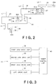
- an exemplary robot 10 includes a robot main body 20 configured to carry a plate member (or work), such as a semiconductor wafer 50 or the like, and a robot control unit 40 configured to control an operation of the robot main body 20.
- a plate member or work
- a robot control unit 40 configured to control an operation of the robot main body 20.
- the robot main body 20 is configured to carry out the semiconductor wafer 50 from a wafer cassette 51 as well as to carry in the semiconductor wafer 50 to the cassette 51. It is noted that the wafer cassette 51 was produced based on the SEMI (Semiconductor Equipment and Materials International) standard.
- the robot main body 20 has a robot base 21.
- a proximal end of a first arm 23 is fixed.
- a proximal end of a second arm 24 is rotatably attached.
- a hand 25 that can serve as an end effector is rotatably provided.
- the hand 25 is configured such that the semiconductor wafer 50 can be placed thereon.
- the hand 25 includes a holding unit 25A utilizing a vacuum suction mechanism and/or grasping mechanism.
- the robot control unit 40 is implemented by a computer and includes a memory 41, in which an operational program for controlling the operation of the robot main body 20 is stored, and a CPU 42 configured to control the robot main body 20 by executing the operational program stored in the memory 41.
- data concerning the instruction point for controlling the operation of the robot main body 20 can also be stored.
- the hand 25 can be moved to a predetermined position based on such instruction point data stored in the memory 41.
- data concerning the shape and size of the hand 25 as well as data concerning the shape and size of the wafer held by the hand 25 can also be stored in the memory 41.
- the second arm 24 is fixedly attached, at its proximal end, to a second arm rotation shaft 26 rotatably provided at the distal end of the first arm 23.
- the hand 25 is fixedly attached, at its proximal end, to a wrist axis 27 rotatably provided at the distal end of the second arm 24.
- the robot arm 28 of the robot main body 20 includes the arm shaft 22, first arm 23, second arm 24, hand 25, second arm rotation shaft 26 and wrist axis 27.
- the robot arm 28 of this type is also referred to as a scalar-type horizontal articulated arm.
- the hand 25 can be moved in the X-axial, Y-axial and Z-axial directions, respectively, to a desired position.
- the robot main body 20 further includes a first arm drive unit 29 configured to rotate the first arm 23, a second arm drive unit 30 configured to rotate the second arm 24, a wrist axis drive unit 31 configured to rotate the wrist axis 27, and a lift drive unit 32 configured to vertically drive the arm shaft 22.
- the first drive unit 29 is located in an internal space of the robot base 21 and includes a servomotor 33 and a power transmission mechanism 34 thereof.
- the second arm drive unit 30 is located in an internal space of the first arm 23 and includes a servomotor 35 and a power transmission mechanism 36 thereof.
- the wrist axis drive unit 31 is located in an internal space of the second arm 24 and includes a servomotor 37 and a power transmission mechanism 38 thereof.
- These servomotors 33, 35, 37 incorporate encoders 33A, 35A, 37A, respectively.
- a gear transmission mechanism including a reduction gear can be used for each power transmission mechanism 34, 36, 38.
- power of each servomotor 33, 35, 37 is first transmitted to an input side of the reduction gear, and the torque is then amplified at a predetermined amplification ratio, while the rotation speed is reduced at a predetermined reduction ratio.
- the resultant power will be outputted from an output side of the reduction gear.
- the arm shaft 22, second arm rotation shaft 26 and wrist axis 27 will be rotated, respectively.
- the first arm 23, second arm 24 and hand 25 will be rotated, respectively.
- the arm shaft 22, second arm rotation shaft 26 and/or wrist axis 27 may be driven by a direct drive motor.
- the lift drive unit 32 is provided in the robot base 21 and implemented by a boll-screw mechanism using a rotary motor, wherein angular displacement of the rotary motor can be optionally controlled.
- the lift drive unit 32 includes a screw rod, a mating member configured to be meshed with the screw rod, and the rotary motor configured to rotate the screw rod.
- the arm shaft 22 is fixed in position to the mating member.
- a servomotor 39 incorporating an encoder 39A is used for the rotary motor of the lift drive unit 32.
- the arm shaft 22 is rotated about a rotation axis L1, relative to the robot base 21, by the first arm drive unit 29. Consequently, the first arm 23 is rotated about the rotation axis L1 relative to the robot base 21.
- the second arm rotation shaft 26 is rotated about a rotation axis L2, relative to the first arm 23, by the second arm drive unit 30.
- the second arm 24 is rotated about the rotation axis L2 relative to the first arm 23.
- the wrist axis 27 is rotated about a rotation axis L3, relative to the second arm 24, by the wrist axis drive unit 31.
- the hand 25 is rotated about the rotation axis L3 relative to the second arm 24.
- the rotation axes L1, L2, L3 are parallel with one another, and extend in the Z-axial direction (or vertical direction), respectively. Namely, the robot arm 28 having such construction as described above can be moved with degrees of freedom in the X-axial, Y-axial and Z-axial directions.
- the robot control unit 40 can perform feed-back control for the drive unit 29, 30, 31, 32 by obtaining angular positions of the servomotors 33, 35, 37, 39 from the encoders 33A, 35A, 37A, 39A of the respective servomotors 33, 35, 37, 39 of the first arm drive unit 29, second arm drive unit 30, wrist axis drive unit 31 and lift drive unit 32, respectively.
- the hand 25 can be aligned with a target position with high accuracy.
- the target is the wafer cassette 51 used for containing the semiconductor wafers 50.
- the CPU 42 of the robot control unit 40 reads temporary positional data concerning the wafer cassette 51 and stored in the memory 41, then controls the first arm drive unit 29, second arm drive unit 30, wrist axis drive unit 31 and lift drive unit 32, respectively, so as to insert each wafer 50 held by the hand 25 into the cassette 51.
- the wafer cassette 51 is sized to be slightly greater than a diameter of the wafer 50 in the horizontal direction between its left and right inner wall faces 52, 53.
- a suitable gap for allowing the wafer 50 to slightly move in the horizontal or lateral direction is provided on each side of the wafer 50 when the wafer 50 is inserted in the cassette 51.
- the robot control unit 40 sets a control loop gain of the wrist axis drive unit 31 at substantially zero (0), while bringing the wafer 50 held by the hand 25 into contact with one inner wall face 52 (or 53) of the cassette 51 (or into a state depicted by imaginary lines in Figs. 4 and 5 ) by controlling and driving at least one of the first arm drive unit 29 and second arm drive unit 30.
- the robot control unit 40 sets the control loop gain of the wrist axis drive unit 31 at substantially zero
- the robot control unit 40 changes the control loop gain into a possibly small value including zero from a servo-gain obtained upon a usual operation.
- contact reaction force that will be generated when some external force is exerted on the wrist axis drive unit 31 or when the hand 25 is in contact with the cassette 51 can be minimized. Therefore, the angular position of the servomotor 37 of the wrist axis drive unit 31 can be changed substantially freely with substantially no influence caused by such contact reaction force. It is noted that this operation also includes setting the control loop gain at zero.
- the hand 25 When the wafer 50 is in contact with the inner wall face 52 (or 53) of the cassette 51, the hand 25 will be angularly displaced about the rotation axis L3 together with the wafer 50, because the control loop gain of the wrist axis drive unit 31 is set at substantially zero. Thus, the wrist axis 27 will also be angularly displaced. Then, this angular displacement of the wrist axis 27 is transmitted to the servomotor 37 via the power transmission mechanism 38, thereby angularly moving the servomotor 37.
- the servomotor 37 will be angularly displaced when the wafer 50 is in contact with the inner wall face 52 (or 53) of the cassette 51.
- a point of time when the servomotor 37 begins to be angularly displaced can be detected by the change of each position of the encoders. Then, a posture of the robot arm 28 and the angular position of the wrist axis 27 at the detected point of time will be detected.
- information about the posture of the robot arm 28 can be obtained from the encoders 33A, 35A, 39A of the respective servomotors 33, 35, 39 of the first arm drive unit 29, second arm drive unit 30 and lift drive unit 32, respectively.
- information about the angular position of the wrist axis 27 can be obtained from the encoder 37A of the servomotor 37 of the wrist axis drive unit 31.
- the robot control unit 40 detects each position of the cassette inner wall face 52 (or 53) in an X-Y plane based on data of the shape and size of the wafer 50 stored in the memory 41 as well as on detection results concerning the posture of the robot arm 28 and the angular position of the wrist axis 27 upon the contact of the wafer 50 with the cassette 51.
- the positional data of the left and right inner wall faces 52, 53 of the wafer cassette 51 can be obtained. Consequently, a central position (or instruction point) in the lateral direction of the wafer cassette 51 can be determined.
- instruction data may be obtained with respect to the inner wall faces 52, 53 of the wafer cassette 51 in different positions in the Z-axial direction. In this manner, the position of the wafer cassette 51 can be determined more accurately.
- control loop gain of the wrist axis drive unit 31 may be set at substantially zero immediately before a point of time when the wafer 50 is expected to be in contact with the cassette inner wall face 52 (or 53), based on each preset temporary positional data of the cassette inner wall faces 52, 53.
- the wrist axis 27 and wrist axis drive unit 31 can serve as the so-called switch upon an instruction operation of the target position. Namely, with the detection of the posture of the robot arm 28 and the rotational position of the wrist axis 27 at a point of time when such a switch is operated, the target position can be detected and instructed.
- the robot 10 of this embodiment is not designed to detect the target position based on a difference between an instruction value and a current value with respect to the operation of the robot arm 28, but is configured to detect the angular displacement of the wrist axis 27 upon the contact.
- the target position can be detected with high accuracy, without being affected by various fluctuation factors and other factors that may be changed with time in the drive system of the robot 10.
- the wafer 50 can be softly contacted with the target, as described above, thereby, inadvertent detachment of the wafer 50 from the hand 25 holding it by vacuum suction upon the contact between the wafer 50 and the target can be securely prevented. Due to the instruction operation by using the robot 10 with the wafer 50 being actually held thereby, significantly accurate instruction data corresponding to a real operation can be obtained.
- the wafer 50 held by the hand 25 is used as a contact member for the target (or cassette 51).
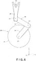
- the hand 25 itself may be used as the contact member. Namely, as shown in Fig. 6 , the hand 25 itself may be softly contacted with a target 54 that is optionally added, with left and right inner faces of the hand 25 being successively contacted with such a target.
- the robot control unit 40 will determine a position of the target 54 in the X-Y plane, based on data of the shape and size of the hand 25 stored in the memory 41 as well as on the posture of the robot arm 28 and the angular position of the wrist axis 27 upon the contact of the hand 25 with the target 54.
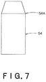
- the target 54 may have a columnar shape having a tapered top end portion.
- the data concerning such a shape of the target 54 may also be stored in the memory 41. Thereafter, the both left and right sides of the hand 25 are successively contacted with the target at a plurality of different positions in the Z-axial direction. Consequently, data about each diameter of the target 54 in the Z-axial direction can be obtained.
Landscapes
- Engineering & Computer Science (AREA)
- Robotics (AREA)
- Mechanical Engineering (AREA)
- Human Computer Interaction (AREA)
- Manufacturing & Machinery (AREA)
- Physics & Mathematics (AREA)
- General Physics & Mathematics (AREA)
- Automation & Control Theory (AREA)
- Manipulator (AREA)
- Container, Conveyance, Adherence, Positioning, Of Wafer (AREA)
- Numerical Control (AREA)
Claims (11)
- Robot comprenant : un bras de robot (24) possédant une extrémité distale sur laquelle un axe de poignet (27) est disposé de manière à pouvoir tourner ; une unité d'entraînement de bras (30) conçue pour déplacer le bras de robot (24) ; une unité d'entraînement d'axe de poignet (31) conçue pour faire tourner l'axe de poignet ; et une unité de commande de robot (40) conçue pour commander l'unité d'entraînement de bras (30) et l'unité d'entraînement d'axe de poignet (31), ladite unité de commande de robot (40) étant conçue pour commander l'unité d'entraînement de bras (30) afin de déplacer l'extrémité distale du bras de robot (24) de façon à amener un élément de contact (50, 25) fixé à l'axe de poignet (27), ledit axe de poignet étant dans un état dans lequel une position angulaire est détectable, en contact avec une cible d'instruction (54), déterminant ainsi une position d'un point d'instruction sur la base d'une posture du bras de robot (24) et de la position angulaire de l'axe de poignet (27) ; caractérisé en ce que :
l'unité de commande de robot est conçue pour régler un gain de boucle de commande de l'unité d'entraînement d'axe de poignet sensiblement égal à zéro à un moment où l'élément de contact est censé être en contact avec la cible d'instruction, sur la base de données de position temporaires prédéfinies concernant la cible d'instruction, pour minimiser la force de réaction de contact générée lorsqu'une force externe est exercée sur l'unité d'entraînement d'axe de poignet, et en ce que l'unité de commande de robot est conçue pour déterminer la position du point d'instruction sur la base de la posture du bras de robot et de la position angulaire de l'axe de poignet au moment où la position angulaire de l'axe de poignet (27) commence à se déplacer en raison du contact entre l'élément de contact (50, 25) et la cible d'instruction (54). - Robot selon la revendication 1, ladite unité d'entraînement d'axe de poignet (31) comprenant un moteur (37) conçu pour faire tourner l'axe de poignet (27), et un codeur (37A) fourni au moteur, et ladite unité de commande de robot (40) étant conçue pour détecter un déplacement angulaire de l'axe de poignet (27) par des changements de la position du codeur (37A).
- Robot selon la revendication 1 ou 2, comprenant en outre un effecteur terminal (25) fixé à l'axe de poignet (27), ledit élément de contact étant l'effecteur terminal.
- Robot selon la revendication 1 ou 2, comprenant en outre un effecteur terminal (25) fixé à l'axe de poignet, ledit élément de contact étant un élément (50) maintenu par l'effecteur terminal.
- Robot selon la revendication 4, ledit effecteur terminal (25) possédant une unité de maintien (25A) conçue pour maintenir un élément plaque (50), ledit élément de contact étant l'élément plaque maintenu par l'effecteur terminal, et ladite cible d'instruction étant un récipient (51) destiné à contenir l'élément plaque.
- Robot selon la revendication 1, ladite unité de commande de robot (40) étant conçue pour régler le gain de boucle de commande à sensiblement zéro immédiatement avant le moment où l'élément de contact (50, 25) est censé être en contact avec la cible d'instruction.
- Robot selon l'une quelconque des revendications 1 à 6, ledit bras de robot (24) étant conçu pour être déplacé tout en présentant des degrés de liberté selon les directions axiale X, axiale Y et axiale Z.
- Robot selon la revendication 7, ladite unité de commande de robot (40) étant conçue pour détecter une pluralité de points d'instruction situés à différentes positions.
- Robot selon l'une quelconque des revendications 1 à 8, ledit axe de poignet (27) pouvant être tourné autour d'un axe de rotation selon la direction axiale Z.
- Robot selon la revendication 9, ledit bras de robot (24) étant conçu pour être déplacé tout en présentant des degrés de liberté selon les directions axiale X, axiale Y et axiale Z, ladite unité de commande de robot (40) étant conçue pour amener l'élément de contact (50, 25) en contact avec la cible dans une pluralité de positions différentes selon la direction axiale Z, ladite cible prenant une position modifiée selon les directions axiale X et axiale Y le long de l'axe Z, moyennant quoi l'unité de commande de robot (40) peut déterminer une position du point d'instruction selon la direction axiale Z sur la base des résultats de détection dans la pluralité de positions différentes.
- Procédé d'instruction du robot défini dans l'une quelconque des revendications 1 à 10 concernant la position du point d'instruction, comprenant :le déplacement de l'extrémité distale du bras de robot (24) en commandant l'unité d'entraînement de bras (30) à l'aide de l'unité de commande de robot (40) de façon à amener l'élément de contact (50, 25) fixé à l'axe de poignet (27), ledit axe de poignet étant dans un état dans lequel une position angulaire est détectable, en contact avec la cible d'instruction (54) ;le réglage d'un gain de boucle de commande de l'unité de commande d'axe de poignet sensiblement à zéro au moment où l'élément de contact est censé être en contact avec la cible d'instruction, sur la base de données de position temporaires prédéfinies concernant la cible d'instruction, afin de minimiser la force de réaction de contact générée lorsqu'une force externe est exercée sur l'unité d'entraînement d'axe de poignet, et la détermination de la position du point d'instruction sur la base de la posture du bras de robot (24) et de la position angulaire de l'axe de poignet (27) à un moment lorsque la position angulaire de l'axe de poignet (27) commence à se déplacer en raison du contact entre l'élément de contact (50, 25) et la cible d'instruction (54).
Applications Claiming Priority (1)
| Application Number | Priority Date | Filing Date | Title |
|---|---|---|---|
| PCT/JP2008/062490 WO2010004635A1 (fr) | 2008-07-10 | 2008-07-10 | Robot et son procédé d'enseignement |
Publications (3)
| Publication Number | Publication Date |
|---|---|
| EP2308657A1 EP2308657A1 (fr) | 2011-04-13 |
| EP2308657A4 EP2308657A4 (fr) | 2012-05-09 |
| EP2308657B1 true EP2308657B1 (fr) | 2019-09-04 |
Family
ID=41506767
Family Applications (1)
| Application Number | Title | Priority Date | Filing Date |
|---|---|---|---|
| EP08778038.3A Active EP2308657B1 (fr) | 2008-07-10 | 2008-07-10 | Robot et son procédé d'apprentissage |
Country Status (5)
| Country | Link |
|---|---|
| US (1) | US8788087B2 (fr) |
| EP (1) | EP2308657B1 (fr) |
| JP (1) | JP5114804B2 (fr) |
| KR (1) | KR101291368B1 (fr) |
| WO (1) | WO2010004635A1 (fr) |
Families Citing this family (10)
| Publication number | Priority date | Publication date | Assignee | Title |
|---|---|---|---|---|
| JP5235376B2 (ja) * | 2007-10-05 | 2013-07-10 | 川崎重工業株式会社 | ロボットのターゲット位置検出装置 |
| JP6148025B2 (ja) | 2013-02-04 | 2017-06-14 | 株式会社Screenホールディングス | 受渡位置教示方法、受渡位置教示装置および基板処理装置 |
| JP6438189B2 (ja) * | 2013-10-01 | 2018-12-12 | 川崎重工業株式会社 | ロボット及びロボットの制御方法 |
| US10054482B2 (en) * | 2014-09-22 | 2018-08-21 | Antonio Maccari | Tool for positioning a scanning device |
| WO2016077387A1 (fr) | 2014-11-10 | 2016-05-19 | Brooks Automation, Inc. | Procédé et appareil d'auto-apprentissage d'outil |
| US10029366B2 (en) * | 2014-11-21 | 2018-07-24 | Canon Kabushiki Kaisha | Control device for motor drive device, control device for multi-axial motor, and control method for motor drive device |
| JP6412955B2 (ja) * | 2014-12-22 | 2018-10-24 | 川崎重工業株式会社 | ロボットシステム及びエンドエフェクタの変形検出方法 |
| CN106956290B (zh) * | 2017-04-17 | 2019-09-10 | 京东方科技集团股份有限公司 | 机械臂及其操作方法、机械臂装置及显示面板生产设备 |
| CN107301415B (zh) * | 2017-08-08 | 2024-03-22 | 方超 | 手势采集系统 |
| JP7169370B2 (ja) * | 2018-12-28 | 2022-11-10 | 川崎重工業株式会社 | ロボット制御装置、ロボットシステム及びロボット制御方法 |
Family Cites Families (11)
| Publication number | Priority date | Publication date | Assignee | Title |
|---|---|---|---|---|
| JPS6254303A (ja) * | 1985-09-03 | 1987-03-10 | Nissan Motor Co Ltd | ロボツトの制御装置 |
| JPH03242703A (ja) * | 1990-02-21 | 1991-10-29 | Fanuc Ltd | モータ制御でのフィードフォアードゲインの学習方法 |
| US5475889A (en) * | 1994-07-15 | 1995-12-19 | Ontrak Systems, Inc. | Automatically adjustable brush assembly for cleaning semiconductor wafers |
| JP3421442B2 (ja) * | 1994-09-02 | 2003-06-30 | ファナック株式会社 | ロボットの位置教示方法及びロボット制御装置 |
| JPH08288365A (ja) * | 1995-04-11 | 1996-11-01 | Miyazaki Oki Electric Co Ltd | ロボットによるウエハ搬送方法及びその装置 |
| US6366830B2 (en) * | 1995-07-10 | 2002-04-02 | Newport Corporation | Self-teaching robot arm position method to compensate for support structure component alignment offset |
| US5789890A (en) * | 1996-03-22 | 1998-08-04 | Genmark Automation | Robot having multiple degrees of freedom |
| DE19910534B4 (de) | 1998-03-14 | 2005-06-30 | Schneider Gmbh + Co. Kg | Verfahren zum Feststellen des Berührens eines Werkzeugs und eines Werkstücks einer optischen Maschine |
| US6242879B1 (en) | 2000-03-13 | 2001-06-05 | Berkeley Process Control, Inc. | Touch calibration system for wafer transfer robot |
| JP4601130B2 (ja) * | 2000-06-29 | 2010-12-22 | 日本エー・エス・エム株式会社 | ウエハーハンドリングロボットのティーチング装置および方法 |
| JP4473827B2 (ja) * | 2006-02-23 | 2010-06-02 | 東京エレクトロン株式会社 | 基板処理装置及び基板の受け渡し位置の調整方法 |
-
2008
- 2008-07-10 JP JP2010519598A patent/JP5114804B2/ja active Active
- 2008-07-10 US US13/003,081 patent/US8788087B2/en active Active
- 2008-07-10 EP EP08778038.3A patent/EP2308657B1/fr active Active
- 2008-07-10 KR KR1020117002036A patent/KR101291368B1/ko active Active
- 2008-07-10 WO PCT/JP2008/062490 patent/WO2010004635A1/fr not_active Ceased
Non-Patent Citations (1)
| Title |
|---|
| None * |
Also Published As
| Publication number | Publication date |
|---|---|
| JPWO2010004635A1 (ja) | 2011-12-22 |
| EP2308657A1 (fr) | 2011-04-13 |
| KR101291368B1 (ko) | 2013-07-30 |
| EP2308657A4 (fr) | 2012-05-09 |
| US8788087B2 (en) | 2014-07-22 |
| KR20110038068A (ko) | 2011-04-13 |
| WO2010004635A1 (fr) | 2010-01-14 |
| JP5114804B2 (ja) | 2013-01-09 |
| US20110118873A1 (en) | 2011-05-19 |
Similar Documents
| Publication | Publication Date | Title |
|---|---|---|
| US8788087B2 (en) | Robot and instruction method thereof | |
| JP5235376B2 (ja) | ロボットのターゲット位置検出装置 | |
| EP2324968B1 (fr) | Robot et son procédé d'enseignement | |
| US10987742B2 (en) | Method of controlling positioning control apparatus and positioning control apparatus | |
| KR940003204B1 (ko) | 제어로봇 | |
| JP5246550B2 (ja) | ロボット及びその制御方法 | |
| CN106493711B (zh) | 控制装置、机器人以及机器人系统 | |
| EP3275603A2 (fr) | Dispositif de commande, robot et système de robot | |
| CN106272416A (zh) | 基于力觉和视觉的机器人细长轴精密装配系统及方法 | |
| CN108068110A (zh) | 控制装置、机器人及机器人系统 | |
| JP5529920B2 (ja) | ロボットのターゲット位置検出装置、半導体装置およびターゲット位置検出方法 | |
| JPH10207519A (ja) | ロボットの制御方式 | |
| JP5401748B2 (ja) | ロボット及びその教示方法 | |
| JP5620463B2 (ja) | ロボットのターゲット位置検出装置 | |
| WO2023062686A1 (fr) | Dispositif de commande de robot et système de robot | |
| JP2649283B2 (ja) | ロボットの加工制御方法 | |
| EP4245478B1 (fr) | Dispositif de commande pour un robot d'assemblage comprenant un capteur de force virtuel pour améliorer l'alignement des surfaces | |
| JP2608307B2 (ja) | ロボット装置 | |
| JPS6288589A (ja) | ロボツト | |
| JPH012883A (ja) | ロボット制御装置 | |
| CN116890333A (zh) | 机器人控制装置、机器人控制方法及存储介质 | |
| WO2022180921A1 (fr) | Système de traitement | |
| JPH0740159A (ja) | 調整方法及びその装置と調整システム | |
| JPH0721734B2 (ja) | 移動体制御装置 |
Legal Events
| Date | Code | Title | Description |
|---|---|---|---|
| PUAI | Public reference made under article 153(3) epc to a published international application that has entered the european phase |
Free format text: ORIGINAL CODE: 0009012 |
|
| 17P | Request for examination filed |
Effective date: 20110209 |
|
| AK | Designated contracting states |
Kind code of ref document: A1 Designated state(s): AT BE BG CH CY CZ DE DK EE ES FI FR GB GR HR HU IE IS IT LI LT LU LV MC MT NL NO PL PT RO SE SI SK TR |
|
| AX | Request for extension of the european patent |
Extension state: AL BA MK RS |
|
| DAX | Request for extension of the european patent (deleted) | ||
| A4 | Supplementary search report drawn up and despatched |
Effective date: 20120412 |
|
| RIC1 | Information provided on ipc code assigned before grant |
Ipc: H01L 21/677 20060101ALI20120404BHEP Ipc: B25J 9/22 20060101AFI20120404BHEP Ipc: G05B 19/42 20060101ALI20120404BHEP |
|
| 17Q | First examination report despatched |
Effective date: 20130204 |
|
| GRAP | Despatch of communication of intention to grant a patent |
Free format text: ORIGINAL CODE: EPIDOSNIGR1 |
|
| STAA | Information on the status of an ep patent application or granted ep patent |
Free format text: STATUS: GRANT OF PATENT IS INTENDED |
|
| INTG | Intention to grant announced |
Effective date: 20190326 |
|
| GRAS | Grant fee paid |
Free format text: ORIGINAL CODE: EPIDOSNIGR3 |
|
| GRAA | (expected) grant |
Free format text: ORIGINAL CODE: 0009210 |
|
| STAA | Information on the status of an ep patent application or granted ep patent |
Free format text: STATUS: THE PATENT HAS BEEN GRANTED |
|
| AK | Designated contracting states |
Kind code of ref document: B1 Designated state(s): AT BE BG CH CY CZ DE DK EE ES FI FR GB GR HR HU IE IS IT LI LT LU LV MC MT NL NO PL PT RO SE SI SK TR |
|
| REG | Reference to a national code |
Ref country code: GB Ref legal event code: FG4D |
|
| REG | Reference to a national code |
Ref country code: CH Ref legal event code: EP |
|
| REG | Reference to a national code |
Ref country code: AT Ref legal event code: REF Ref document number: 1174721 Country of ref document: AT Kind code of ref document: T Effective date: 20190915 |
|
| REG | Reference to a national code |
Ref country code: DE Ref legal event code: R096 Ref document number: 602008061111 Country of ref document: DE |
|
| REG | Reference to a national code |
Ref country code: IE Ref legal event code: FG4D |
|
| REG | Reference to a national code |
Ref country code: NL Ref legal event code: MP Effective date: 20190904 |
|
| REG | Reference to a national code |
Ref country code: LT Ref legal event code: MG4D |
|
| PG25 | Lapsed in a contracting state [announced via postgrant information from national office to epo] |
Ref country code: HR Free format text: LAPSE BECAUSE OF FAILURE TO SUBMIT A TRANSLATION OF THE DESCRIPTION OR TO PAY THE FEE WITHIN THE PRESCRIBED TIME-LIMIT Effective date: 20190904 Ref country code: BG Free format text: LAPSE BECAUSE OF FAILURE TO SUBMIT A TRANSLATION OF THE DESCRIPTION OR TO PAY THE FEE WITHIN THE PRESCRIBED TIME-LIMIT Effective date: 20191204 Ref country code: LT Free format text: LAPSE BECAUSE OF FAILURE TO SUBMIT A TRANSLATION OF THE DESCRIPTION OR TO PAY THE FEE WITHIN THE PRESCRIBED TIME-LIMIT Effective date: 20190904 Ref country code: SE Free format text: LAPSE BECAUSE OF FAILURE TO SUBMIT A TRANSLATION OF THE DESCRIPTION OR TO PAY THE FEE WITHIN THE PRESCRIBED TIME-LIMIT Effective date: 20190904 Ref country code: NO Free format text: LAPSE BECAUSE OF FAILURE TO SUBMIT A TRANSLATION OF THE DESCRIPTION OR TO PAY THE FEE WITHIN THE PRESCRIBED TIME-LIMIT Effective date: 20191204 Ref country code: FI Free format text: LAPSE BECAUSE OF FAILURE TO SUBMIT A TRANSLATION OF THE DESCRIPTION OR TO PAY THE FEE WITHIN THE PRESCRIBED TIME-LIMIT Effective date: 20190904 |
|
| PG25 | Lapsed in a contracting state [announced via postgrant information from national office to epo] |
Ref country code: ES Free format text: LAPSE BECAUSE OF FAILURE TO SUBMIT A TRANSLATION OF THE DESCRIPTION OR TO PAY THE FEE WITHIN THE PRESCRIBED TIME-LIMIT Effective date: 20190904 Ref country code: GR Free format text: LAPSE BECAUSE OF FAILURE TO SUBMIT A TRANSLATION OF THE DESCRIPTION OR TO PAY THE FEE WITHIN THE PRESCRIBED TIME-LIMIT Effective date: 20191205 Ref country code: LV Free format text: LAPSE BECAUSE OF FAILURE TO SUBMIT A TRANSLATION OF THE DESCRIPTION OR TO PAY THE FEE WITHIN THE PRESCRIBED TIME-LIMIT Effective date: 20190904 |
|
| REG | Reference to a national code |
Ref country code: AT Ref legal event code: MK05 Ref document number: 1174721 Country of ref document: AT Kind code of ref document: T Effective date: 20190904 |
|
| PG25 | Lapsed in a contracting state [announced via postgrant information from national office to epo] |
Ref country code: NL Free format text: LAPSE BECAUSE OF FAILURE TO SUBMIT A TRANSLATION OF THE DESCRIPTION OR TO PAY THE FEE WITHIN THE PRESCRIBED TIME-LIMIT Effective date: 20190904 Ref country code: AT Free format text: LAPSE BECAUSE OF FAILURE TO SUBMIT A TRANSLATION OF THE DESCRIPTION OR TO PAY THE FEE WITHIN THE PRESCRIBED TIME-LIMIT Effective date: 20190904 Ref country code: EE Free format text: LAPSE BECAUSE OF FAILURE TO SUBMIT A TRANSLATION OF THE DESCRIPTION OR TO PAY THE FEE WITHIN THE PRESCRIBED TIME-LIMIT Effective date: 20190904 Ref country code: PT Free format text: LAPSE BECAUSE OF FAILURE TO SUBMIT A TRANSLATION OF THE DESCRIPTION OR TO PAY THE FEE WITHIN THE PRESCRIBED TIME-LIMIT Effective date: 20200106 Ref country code: RO Free format text: LAPSE BECAUSE OF FAILURE TO SUBMIT A TRANSLATION OF THE DESCRIPTION OR TO PAY THE FEE WITHIN THE PRESCRIBED TIME-LIMIT Effective date: 20190904 Ref country code: PL Free format text: LAPSE BECAUSE OF FAILURE TO SUBMIT A TRANSLATION OF THE DESCRIPTION OR TO PAY THE FEE WITHIN THE PRESCRIBED TIME-LIMIT Effective date: 20190904 |
|
| PG25 | Lapsed in a contracting state [announced via postgrant information from national office to epo] |
Ref country code: SK Free format text: LAPSE BECAUSE OF FAILURE TO SUBMIT A TRANSLATION OF THE DESCRIPTION OR TO PAY THE FEE WITHIN THE PRESCRIBED TIME-LIMIT Effective date: 20190904 Ref country code: IS Free format text: LAPSE BECAUSE OF FAILURE TO SUBMIT A TRANSLATION OF THE DESCRIPTION OR TO PAY THE FEE WITHIN THE PRESCRIBED TIME-LIMIT Effective date: 20200224 Ref country code: CZ Free format text: LAPSE BECAUSE OF FAILURE TO SUBMIT A TRANSLATION OF THE DESCRIPTION OR TO PAY THE FEE WITHIN THE PRESCRIBED TIME-LIMIT Effective date: 20190904 |
|
| REG | Reference to a national code |
Ref country code: DE Ref legal event code: R097 Ref document number: 602008061111 Country of ref document: DE |
|
| PLBE | No opposition filed within time limit |
Free format text: ORIGINAL CODE: 0009261 |
|
| STAA | Information on the status of an ep patent application or granted ep patent |
Free format text: STATUS: NO OPPOSITION FILED WITHIN TIME LIMIT |
|
| PG2D | Information on lapse in contracting state deleted |
Ref country code: IS |
|
| PG25 | Lapsed in a contracting state [announced via postgrant information from national office to epo] |
Ref country code: DK Free format text: LAPSE BECAUSE OF FAILURE TO SUBMIT A TRANSLATION OF THE DESCRIPTION OR TO PAY THE FEE WITHIN THE PRESCRIBED TIME-LIMIT Effective date: 20190904 Ref country code: IS Free format text: LAPSE BECAUSE OF FAILURE TO SUBMIT A TRANSLATION OF THE DESCRIPTION OR TO PAY THE FEE WITHIN THE PRESCRIBED TIME-LIMIT Effective date: 20200105 |
|
| 26N | No opposition filed |
Effective date: 20200605 |
|
| PG25 | Lapsed in a contracting state [announced via postgrant information from national office to epo] |
Ref country code: SI Free format text: LAPSE BECAUSE OF FAILURE TO SUBMIT A TRANSLATION OF THE DESCRIPTION OR TO PAY THE FEE WITHIN THE PRESCRIBED TIME-LIMIT Effective date: 20190904 |
|
| PG25 | Lapsed in a contracting state [announced via postgrant information from national office to epo] |
Ref country code: MC Free format text: LAPSE BECAUSE OF FAILURE TO SUBMIT A TRANSLATION OF THE DESCRIPTION OR TO PAY THE FEE WITHIN THE PRESCRIBED TIME-LIMIT Effective date: 20190904 |
|
| REG | Reference to a national code |
Ref country code: CH Ref legal event code: PL |
|
| REG | Reference to a national code |
Ref country code: BE Ref legal event code: MM Effective date: 20200731 |
|
| PG25 | Lapsed in a contracting state [announced via postgrant information from national office to epo] |
Ref country code: CH Free format text: LAPSE BECAUSE OF NON-PAYMENT OF DUE FEES Effective date: 20200731 Ref country code: LI Free format text: LAPSE BECAUSE OF NON-PAYMENT OF DUE FEES Effective date: 20200731 Ref country code: LU Free format text: LAPSE BECAUSE OF NON-PAYMENT OF DUE FEES Effective date: 20200710 |
|
| PG25 | Lapsed in a contracting state [announced via postgrant information from national office to epo] |
Ref country code: BE Free format text: LAPSE BECAUSE OF NON-PAYMENT OF DUE FEES Effective date: 20200731 |
|
| PG25 | Lapsed in a contracting state [announced via postgrant information from national office to epo] |
Ref country code: IE Free format text: LAPSE BECAUSE OF NON-PAYMENT OF DUE FEES Effective date: 20200710 |
|
| PG25 | Lapsed in a contracting state [announced via postgrant information from national office to epo] |
Ref country code: TR Free format text: LAPSE BECAUSE OF FAILURE TO SUBMIT A TRANSLATION OF THE DESCRIPTION OR TO PAY THE FEE WITHIN THE PRESCRIBED TIME-LIMIT Effective date: 20190904 Ref country code: MT Free format text: LAPSE BECAUSE OF FAILURE TO SUBMIT A TRANSLATION OF THE DESCRIPTION OR TO PAY THE FEE WITHIN THE PRESCRIBED TIME-LIMIT Effective date: 20190904 Ref country code: CY Free format text: LAPSE BECAUSE OF FAILURE TO SUBMIT A TRANSLATION OF THE DESCRIPTION OR TO PAY THE FEE WITHIN THE PRESCRIBED TIME-LIMIT Effective date: 20190904 |
|
| PGFP | Annual fee paid to national office [announced via postgrant information from national office to epo] |
Ref country code: DE Payment date: 20250528 Year of fee payment: 18 |
|
| PGFP | Annual fee paid to national office [announced via postgrant information from national office to epo] |
Ref country code: GB Payment date: 20260601 Year of fee payment: 19 |
|
| PGFP | Annual fee paid to national office [announced via postgrant information from national office to epo] |
Ref country code: IT Payment date: 20260622 Year of fee payment: 19 |
|
| PGFP | Annual fee paid to national office [announced via postgrant information from national office to epo] |
Ref country code: FR Payment date: 20260608 Year of fee payment: 19 |