EP2308660A2 - Moule pour la fabrication de corps de moulage et procédé de fabrication d'un moule pour la fabrication de corps de moulage - Google Patents
Moule pour la fabrication de corps de moulage et procédé de fabrication d'un moule pour la fabrication de corps de moulage Download PDFInfo
- Publication number
- EP2308660A2 EP2308660A2 EP10009337A EP10009337A EP2308660A2 EP 2308660 A2 EP2308660 A2 EP 2308660A2 EP 10009337 A EP10009337 A EP 10009337A EP 10009337 A EP10009337 A EP 10009337A EP 2308660 A2 EP2308660 A2 EP 2308660A2
- Authority
- EP
- European Patent Office
- Prior art keywords
- mold
- frame
- insert
- production
- moldings
- Prior art date
- Legal status (The legal status is an assumption and is not a legal conclusion. Google has not performed a legal analysis and makes no representation as to the accuracy of the status listed.)
- Granted
Links
Images








Classifications
-
- B—PERFORMING OPERATIONS; TRANSPORTING
- B28—WORKING CEMENT, CLAY, OR STONE
- B28B—SHAPING CLAY OR OTHER CERAMIC COMPOSITIONS; SHAPING SLAG; SHAPING MIXTURES CONTAINING CEMENTITIOUS MATERIAL, e.g. PLASTER
- B28B1/00—Producing shaped prefabricated articles from the material
- B28B1/08—Producing shaped prefabricated articles from the material by vibrating or jolting
- B28B1/081—Vibration-absorbing means
-
- B—PERFORMING OPERATIONS; TRANSPORTING
- B28—WORKING CEMENT, CLAY, OR STONE
- B28B—SHAPING CLAY OR OTHER CERAMIC COMPOSITIONS; SHAPING SLAG; SHAPING MIXTURES CONTAINING CEMENTITIOUS MATERIAL, e.g. PLASTER
- B28B7/00—Moulds; Cores; Mandrels
- B28B7/0002—Auxiliary parts or elements of the mould
- B28B7/0014—Fastening means for mould parts, e.g. for attaching mould walls on mould tables; Mould clamps
-
- B—PERFORMING OPERATIONS; TRANSPORTING
- B28—WORKING CEMENT, CLAY, OR STONE
- B28B—SHAPING CLAY OR OTHER CERAMIC COMPOSITIONS; SHAPING SLAG; SHAPING MIXTURES CONTAINING CEMENTITIOUS MATERIAL, e.g. PLASTER
- B28B7/00—Moulds; Cores; Mandrels
- B28B7/26—Assemblies of separate moulds, i.e. of moulds or moulding space units, each forming a complete mould or moulding space unit independently from each other
-
- B—PERFORMING OPERATIONS; TRANSPORTING
- B28—WORKING CEMENT, CLAY, OR STONE
- B28B—SHAPING CLAY OR OTHER CERAMIC COMPOSITIONS; SHAPING SLAG; SHAPING MIXTURES CONTAINING CEMENTITIOUS MATERIAL, e.g. PLASTER
- B28B7/00—Moulds; Cores; Mandrels
- B28B7/34—Moulds, cores, or mandrels of special material, e.g. destructible materials
- B28B7/346—Manufacture of moulds
-
- B—PERFORMING OPERATIONS; TRANSPORTING
- B30—PRESSES
- B30B—PRESSES IN GENERAL
- B30B15/00—Details of, or accessories for, presses; Auxiliary measures in connection with pressing
- B30B15/02—Dies; Inserts therefor; Mounting thereof; Moulds
- B30B15/022—Moulds for compacting material in powder, granular of pasta form
Definitions
- a mold for the production of moldings, in particular of concrete moldings which comprises a mold frame, at least one mold insert with at least one mold cavity and a mold insert at least partially surrounding elastic insert, wherein the insert in a frame-shaped space between side parts of the mold frame and the mold insert and is arranged between the mold inserts and connects them.
- Such forms are limited in use of rubber or other shrinking in the production materials, which are used as elastic insert, in their life, since these deposits are already after the production of the mold under tension and then in the production of molded blocks in particular in opposite directions Vibrations between the mold frame and the mold inserts are burdened by additional entsteherde voltages.
- the insert can absorb a greater number of oscillations and / or oscillations of greater amplitude with less stress.
- the core of the invention is thus a mold for the production of moldings, in which the mold frame and the mold insert or molds are connected by an elastic insert, which is in a largely relaxed or tension-free state.
- the mold can receive in particular counter-rotating vibrations, which occur in particular as a result of a different weight of the mold frame and mold insert or mold inserts in the process of shaking, with less stress than known forms. This has a positive effect on the life of the mold.
- the invention provides, in particular, to perform the retightening during shrinkage by means of side parts, which are formed by the frame parts of the mold frame itself.
- side parts which are formed by the frame parts of the mold frame itself.
- a restressable shape is formed, which the, Basic components of the mold frame uses and manages with a minimum of additional components.
- the invention provides to form the mold frame from at least two individual frame parts. This makes it possible to realize a re-tensionable form with little effort.
- the mold frame of two frame parts it is particularly provided to form an angle from each two adjacent legs of the mold frame and screw the two angles together.
- the molding frame of four frame parts it is particularly intended to pull together the four frame parts at their contact points by means of screws. As a result, it is possible with little effort to create stable mold frames which approach the mold insert when tightening the connecting means from four spatial directions.
- the side parts by means of which the retightening is made possible, form as strips placed on frame parts of the mold frame.
- the side panels are mounted as movable side panels.
- an upper side of the insert or of the mold inserts which defines a second plane, opposite an upper side of the mold frame, which defines a first plane which is aligned parallel to a support plane of a mold support, on which the mold is attached the production of the molded blocks rests to order a distance (Z2) set back and to provide the or the mold inserts in particular with a chamfer, on which the insert passes into the top of the mold insert or the mold inserts.
- the invention provides, an underside of the mold frame, which defines a third plane parallel to an underside of the mold insert or the mold inserts, which defines a fourth plane to align at a distance (Z1), wherein the underside of the mold insert or the Mold inserts forms a contact surface, with which the mold rests on the production base in the production of moldings and wherein the mold frame in the molding production has a distance Z1 to the production base, wherein the distance Z1 is smaller than the distance Z2.
- the inventive method for producing a mold for the production of moldings provides to reduce a volume of the space for the insert during a Temper michsreaes in which the elastic insert is heated, by a symmetrical displacement of side parts of the mold frame.
- the insert connects after the shrinkage process, which preferably takes place by supplying heat over a longer period of time, the mold frame and the at least one mold insert in a largely stress-free state.
- the insert can produce a greater number of oscillations with less stress and / or absorb vibrations having a larger amplitude.
- the core of the invention is thus a mold for the production of moldings, in which the mold frame and the mold insert or molds are connected by an elastic insert, which is in a largely relaxed or tension-free state.
- the mold in particular counter-oscillations, which occur in particular as a result of a different weight of the mold frame and mold insert or mold inserts in the process of shaking, record with less stress than known forms. This has a positive effect on the life of the mold.
- the invention provides to reduce the volume of the gap to the extent in which the elastic insert shrinks in the Temper michsrea. This will build up throughout the process. Tensile stresses avoided.
- the invention provides for further reducing the volume of the interspace after the end of the tempering process by further displacing side parts of the mold frame in order to build up compressive stresses in the elastic insert.
- a mold with a pressure-biased insert allows a particularly good and permanent erection of the Fornrahmens on the or the mold inserts.
- FIG. 1 is a first embodiment of a Form 1 according to the invention shown in plan view.
- the mold 1 essentially comprises a mold insert 2 with mold cavities 3, a mold frame 4 and an elastic insert 5.
- moldings 6 are produced, which are designed as concrete moldings 7.
- the mold frame 4 and the mold insert 2 are connected to each other by means of the elastic insert 5, wherein the elastic insert 5 fills a gap 16 between the mold frame 4 and the mold insert and adheres both to the mold frame 4 and to the mold insert 2.
- the mold frame 4 comprises four side parts 8a to 8d, which are formed as frame parts 9a to 9d.
- a respective forming flange 10, 11 is formed, on which the mold 1 is clamped in the above-mentioned stone paver on a mold support.
- the connection of the side parts 8a to 8d or the frame parts 9a to 9d of the in the FIG. 1 Form 1 is shown on the FIG. 5 and their description.
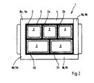
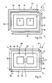
- FIG. 2 is a second embodiment of a form 1 according to the invention shown in plan view. Unlike the one in the FIG. 1 the first variant shown, the second variant five mold inserts 2a to 2e, each with a mold cavity 3 on.
- An elastic insert 5 not only connects a mold frame 4, which, as in the FIG. 1 shown mold frame, with the mold inserts 2, 2a, 2b, 2c and 2d, but also the mold inserts 2, 2a, 2b, 2c and 2d with each other.
- the four of the side parts 8a to 8d or four frame parts 9a to 9d existing mold frame 4 is again on the FIG. 5 and their description.
- opposite frame parts 9a, 9c and 9b, 9d move toward each other in a symmetrical movement in the direction of the center Z.
- the initial width B1 of the elastic insert 5 is gradually reduced to a width B2 to compensate for the shrinkage of the elastic insert 5 during the tempering process and the elastic Insert 5 to keep largely tension-free.
- the invention provides, in particular, for carrying out the tempering process as a vulcanization process, wherein in the case of a vulcanization process the insert consists of rubber or has rubber parts or consists of other vulcanizable materials.
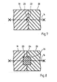
- FIG. 8 is a further sectional view through the mold frame 4 according to the in the FIG. 6 shown section line VIII-VIII.
- the angle 19 and the angle 20 when tightening the connecting means 14 by a sliding block 24 are aligned.
- the sliding block 24 is located opposite grooves 25, 26 of the angle 19, 20.
- a further bore 33 extending in the direction of the arrow z is made, into which the round bolt 29 is inserted, wherein the first bore 32, which passes through the frame part 9a and the frame part 9d, opens into the second bore 33, so that when plugged round pin 29, the guided through the first bore 32 screw 27 screwed into the thread 29a of the round bolt 29 can be.
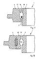
- FIG. 10 is a second connection variant for the frame parts 9a, 9d of in the FIG. 5 Shown form frame 4 shown in a section corresponding to the section line XX. Unlike the one in the FIG. 9 shown connection variant is omitted here on the use of a centering sleeve and the introduction of grooves in the frame parts 9a and 9d.
- the connecting means 14 according to the second embodiment comprises only one Screw 27 and a round bolt 29 with thread 29a. To guide these two components are in the frame parts 9 a and 9 d as in the in the FIG. 9 shown embodiment, two mutually perpendicular bungs 32, 33 executed.
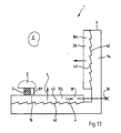
- FIG. 13 In plan view, a detail of another embodiment of a mold 1 is shown. Analogous to that in the FIG. 12 shown embodiment, strips 35b and 35c are again formed as wedges 39. However, for a frame part 9a of a mold frame 4, these have a multi-tooth profile 42, which interacts with multi-tooth profiles 43 executed on the frame part 9a.
- FIG. 12 Moves the bar 35c in an arrow direction x, which is generated by means of a movement means 36, to an additional movement of the bar 35c in an arrow direction y in the direction of a center Z of the form 1. This in turn leaves a width B1 of a gap 16 between reduce a mold insert 2 and the mold frame 4 to compensate for the shrinkage of an elastic insert 5.
- FIG. 16 is another cut through in the FIG. 14 shown form 1 along a section line XVI-XVI shown.
- an oblique contact surface 47 of a strip 35c and an inclined contact surface 48 of the mold insert 2 are arranged such that the strip 35c will be raised by means of a screw 51 shown diagrammatically in an arrow direction d.
- the width B1 available for the elastic insert 5 is reduced.
- a clamping of the mold frame 4 takes place against the mold insert 2 and against the elastic insert 5 on the longitudinal sides 52, 53 of the mold 1 (see also FIG. 14 ) by lifting the bar 35c and on transverse sides 54, 55 of the mold 1 (see also FIG. 14 ) by lowering the strips 35b.
- This counteracting mode of action prevents the mold insert 2 from being pushed out of the mold frame 4 during clamping upwards in the z-direction or downwards in the z'-direction.
- FIG. 18 can be shown by a multipart Embodiment of the mold frame 4 an individual formation of a contact surface 59 are made, which has the mold frame 4 to the gap 16 out.
- the mold frame 4 as additional components moldings 60, which are attached to the mold frame 4 and have the desired profile.
- FIGS. 19 and 20 show with respect to the FIG. 6 and the sectional profiles XIX-XIX and xx-xx shown there, two further embodiments for the connection of the angle 19, 20 of the mold frame 4, wherein for the sake of clarity in the FIG. 19 was omitted on a hatching cut surfaces.
- the angles 19 and 20 are aligned by cooperating, matched tooth profiles 61, 62 to each other and additionally connected by a connecting means 14.
- a connecting means 14 is used which comprises a centering sleeve 63, a screw 64 and a nut 65.
- FIG. 21 shows a schematic sectional view of an embodiment of a erfindunlinien form 1, wherein the mold 1 rests on a production base 66.
- the elastic insert 5 and the mold insert 2 with a mold cavity 3 can be seen.
- the mold frame 4 has an upper side 67, which defines a plane 68.
- the mold frame 4 has a lower side 69, which defines a plane 70.
- the mold insert 2 has an upper side 71 which defines a plane 72 and finally the mold insert 2 has a lower side 73 which defines a plane 74.
- the bottom 73 serves as a contact surface A73, with which the mold 1 rests on the production support 66.
- the upper plane 72 of the mold insert 2 is opposite the plane 68 of the mold frame 4 set back in the vertical direction z by a dimension Z2 in the direction of the production base 66. Furthermore, the lower plane 70 of the mold frame 4 to a support plane formed by the production base 66 E66 and to the lower level 74 of the mold insert 2 in a vertical direction z measured distance Z1. In this case, the distance Z1 is measured as long as the mold 1 is not yet clamped onto the production base 66. For the ratio of the distances Z1 and Z2, Z2> Z1.
- the chamfer 75 preferably extends in the x-direction over a distance X1 of 5 mm to 10 mm and in the z-direction over a height Z2 of 1 mm to 2 mm.
- a width B3 is shown, which assumes a frame-shaped gap 16 which is filled with an elastic insert 5, when the insert 5 is shrunk and biased.
- the mold 1 essentially comprises a mold frame 4, a mold insert 2 with two mold cavities 3 and an elastic insert 5 surrounding the mold insert 2.
- the mold frame 4 is formed in the present case from two angles 19, 20, whose legs are designed as frame parts 9a to 9d are. The angles 19, 20 are over in the FIGS. 24 to 26 symbolically illustrated connecting means 14 connected.
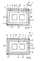
- the mold 1 is shown in a position P0, in which the mold frame 4 is still without contact with the elastic insert. 5 is, which already surrounds the mold insert 2.
- the tempering process is in the in the FIG. 25 shown position P2 completed and the elastic insert 5 is tension-free between the Fcrmrahen 4 and the mold insert 2 and is adhesively connected thereto. With dashed lines the dimensions are indicated, which had the elastic insert 5 before the beginning of the tempering process.
Landscapes
- Engineering & Computer Science (AREA)
- Mechanical Engineering (AREA)
- Manufacturing & Machinery (AREA)
- Chemical & Material Sciences (AREA)
- Ceramic Engineering (AREA)
- Moulds For Moulding Plastics Or The Like (AREA)
- Manufacturing Of Tubular Articles Or Embedded Moulded Articles (AREA)
- Moulds, Cores, Or Mandrels (AREA)
Priority Applications (1)
| Application Number | Priority Date | Filing Date | Title |
|---|---|---|---|
| PL10009337T PL2308660T3 (pl) | 2009-10-07 | 2010-09-08 | Forma do wytwarzania kształtek i sposób wytwarzania takiej formy do wytwarzania kształtek |
Applications Claiming Priority (1)
| Application Number | Priority Date | Filing Date | Title |
|---|---|---|---|
| DE102009048599A DE102009048599A1 (de) | 2009-10-07 | 2009-10-07 | Form zur Herstellung von Formkörpern und Verfahren zur Herstellung einer Form für die Herstellung von Formkörpern |
Publications (3)
| Publication Number | Publication Date |
|---|---|
| EP2308660A2 true EP2308660A2 (fr) | 2011-04-13 |
| EP2308660A3 EP2308660A3 (fr) | 2012-01-25 |
| EP2308660B1 EP2308660B1 (fr) | 2013-04-24 |
Family
ID=43466481
Family Applications (1)
| Application Number | Title | Priority Date | Filing Date |
|---|---|---|---|
| EP10009337.6A Active EP2308660B1 (fr) | 2009-10-07 | 2010-09-08 | Moule pour la fabrication de corps de moulage et procédé de fabrication d'un moule pour la fabrication de corps moulés |
Country Status (4)
| Country | Link |
|---|---|
| EP (1) | EP2308660B1 (fr) |
| DE (1) | DE102009048599A1 (fr) |
| DK (1) | DK2308660T3 (fr) |
| PL (1) | PL2308660T3 (fr) |
Citations (1)
| Publication number | Priority date | Publication date | Assignee | Title |
|---|---|---|---|---|
| EP0738204B1 (fr) | 1994-01-07 | 1997-12-17 | Maskin Industri Viborg A/S | Moule |
Family Cites Families (2)
| Publication number | Priority date | Publication date | Assignee | Title |
|---|---|---|---|---|
| DE10114398A1 (de) * | 2001-03-23 | 2002-09-26 | Kobra Formen Gmbh | Formrahmen für eine Form |
| DE102006026115A1 (de) * | 2006-06-03 | 2007-12-06 | Kobra Formen Gmbh | Anordnung zur Herstellung von Betonformsteinen, Form für eine solche Anordnung und Verfahren zur Herstellung einer solchen Form |
-
2009
- 2009-10-07 DE DE102009048599A patent/DE102009048599A1/de not_active Withdrawn
-
2010
- 2010-09-08 EP EP10009337.6A patent/EP2308660B1/fr active Active
- 2010-09-08 PL PL10009337T patent/PL2308660T3/pl unknown
- 2010-09-08 DK DK10009337.6T patent/DK2308660T3/da active
Patent Citations (1)
| Publication number | Priority date | Publication date | Assignee | Title |
|---|---|---|---|---|
| EP0738204B1 (fr) | 1994-01-07 | 1997-12-17 | Maskin Industri Viborg A/S | Moule |
Also Published As
| Publication number | Publication date |
|---|---|
| EP2308660B1 (fr) | 2013-04-24 |
| PL2308660T3 (pl) | 2013-09-30 |
| DE102009048599A1 (de) | 2011-04-14 |
| EP2308660A3 (fr) | 2012-01-25 |
| DK2308660T3 (da) | 2013-07-15 |
Similar Documents
| Publication | Publication Date | Title |
|---|---|---|
| EP3615357B1 (fr) | Bras de suspension | |
| EP2598267B1 (fr) | Matrice et procédé de forgeage | |
| EP1682390A1 (fr) | Palier d'essuie-glace | |
| AT520325B1 (de) | Formgebungsmaschine | |
| AT506606B1 (de) | Spritzgiesswerkzeug | |
| DE202024101337U1 (de) | Eckverbinder | |
| EP0933181A2 (fr) | Dispositif de fermeture de moules pour la fabrication d'objets en résine thermoplastique | |
| EP2308660B1 (fr) | Moule pour la fabrication de corps de moulage et procédé de fabrication d'un moule pour la fabrication de corps moulés | |
| EP1967341A2 (fr) | Forme destinée à la fabrication de pierres en béton et procédé de fabrication d'un agencement de noyau d'un tel moule | |
| EP1674226B1 (fr) | Dispositif de moulage avec un moule et procédé pour la fabrication de blocs en béton | |
| EP1872927B1 (fr) | Plaque de calibrage pour un outil d'extrusion destiné à la fabrication de profilés en plastique | |
| EP1548196A1 (fr) | Elément de connection pour une liaison à haute résistance à la flexion entre éléments de construction | |
| EP2742190B1 (fr) | Élément d'isolation thermique | |
| DE102007019388A1 (de) | Form zur Herstellung von Betonformsteinen und Verfahren zu deren Herstellung | |
| DE102013201068A1 (de) | Verfahren und Vorrichtung zur Herstellung eines Trägers für eine Kranbrücke | |
| EP2498969B1 (fr) | Dispositif de serrage de buse et une machine de moulage par injection avec un tel dispositif | |
| EP1063361A2 (fr) | Gabarit de montage et procédé de montage d'un élément préfabriqué sur une partie de bâtiment | |
| DE202018106169U1 (de) | Einrichtung zur Stabilisierung der Stirnseiten von Betonfertigteilen | |
| DE1504771A1 (de) | Verfahren und Vorrichtung zur Herstellung eines Bolzens oder Stabes aus glasfaserverstaerktem Kunststoff | |
| AT504317B1 (de) | Keramikkírper für ein abstimmelement und verfahren zu dessen herstellung | |
| DE1684224A1 (de) | Verfahren und Vorrichtung zur Erstellung von Bauwerken durch Aneinandersetzen vorgefertigter Bauelemente | |
| DE102024107530A1 (de) | Eckverbinder | |
| DE102022120073A1 (de) | Verfahren zur Herstellung kernloser Faserverbundbauteile und Wickelstift für ein Faserverbundbauteil | |
| DE102020132441A1 (de) | System zur Befestigung, Anordnung zur Befestigung einer Schiene und Verfahren zur Reparatur einer solchen Anordnung | |
| DE102021130617A1 (de) | Hohlachse und Hohlachsset zur Anordnung eines Trittelements eines Personenbeförderungsbands an einer Antriebskette |
Legal Events
| Date | Code | Title | Description |
|---|---|---|---|
| PUAI | Public reference made under article 153(3) epc to a published international application that has entered the european phase |
Free format text: ORIGINAL CODE: 0009012 |
|
| AK | Designated contracting states |
Kind code of ref document: A2 Designated state(s): AL AT BE BG CH CY CZ DE DK EE ES FI FR GB GR HR HU IE IS IT LI LT LU LV MC MK MT NL NO PL PT RO SE SI SK SM TR |
|
| AX | Request for extension of the european patent |
Extension state: BA ME RS |
|
| PUAL | Search report despatched |
Free format text: ORIGINAL CODE: 0009013 |
|
| AK | Designated contracting states |
Kind code of ref document: A3 Designated state(s): AL AT BE BG CH CY CZ DE DK EE ES FI FR GB GR HR HU IE IS IT LI LT LU LV MC MK MT NL NO PL PT RO SE SI SK SM TR |
|
| AX | Request for extension of the european patent |
Extension state: BA ME RS |
|
| RIC1 | Information provided on ipc code assigned before grant |
Ipc: B28B 7/26 20060101ALI20111222BHEP Ipc: B28B 1/08 20060101AFI20111222BHEP Ipc: B28B 7/34 20060101ALI20111222BHEP Ipc: B28B 7/00 20060101ALI20111222BHEP |
|
| 17P | Request for examination filed |
Effective date: 20120427 |
|
| GRAP | Despatch of communication of intention to grant a patent |
Free format text: ORIGINAL CODE: EPIDOSNIGR1 |
|
| RIC1 | Information provided on ipc code assigned before grant |
Ipc: B28B 7/34 20060101ALI20120814BHEP Ipc: B28B 7/00 20060101ALI20120814BHEP Ipc: B28B 7/26 20060101ALI20120814BHEP Ipc: B28B 1/08 20060101AFI20120814BHEP Ipc: B30B 15/02 20060101ALI20120814BHEP |
|
| GRAS | Grant fee paid |
Free format text: ORIGINAL CODE: EPIDOSNIGR3 |
|
| GRAP | Despatch of communication of intention to grant a patent |
Free format text: ORIGINAL CODE: EPIDOSNIGR1 |
|
| GRAA | (expected) grant |
Free format text: ORIGINAL CODE: 0009210 |
|
| AK | Designated contracting states |
Kind code of ref document: B1 Designated state(s): AL AT BE BG CH CY CZ DE DK EE ES FI FR GB GR HR HU IE IS IT LI LT LU LV MC MK MT NL NO PL PT RO SE SI SK SM TR |
|
| REG | Reference to a national code |
Ref country code: GB Ref legal event code: FG4D Free format text: NOT ENGLISH |
|
| REG | Reference to a national code |
Ref country code: CH Ref legal event code: EP |
|
| REG | Reference to a national code |
Ref country code: AT Ref legal event code: REF Ref document number: 608317 Country of ref document: AT Kind code of ref document: T Effective date: 20130515 |
|
| REG | Reference to a national code |
Ref country code: IE Ref legal event code: FG4D Free format text: LANGUAGE OF EP DOCUMENT: GERMAN |
|
| REG | Reference to a national code |
Ref country code: DE Ref legal event code: R096 Ref document number: 502010003048 Country of ref document: DE Effective date: 20130620 |
|
| REG | Reference to a national code |
Ref country code: DK Ref legal event code: T3 |
|
| REG | Reference to a national code |
Ref country code: LT Ref legal event code: MG4D |
|
| REG | Reference to a national code |
Ref country code: PL Ref legal event code: T3 |
|
| REG | Reference to a national code |
Ref country code: NL Ref legal event code: VDEP Effective date: 20130424 |
|
| PG25 | Lapsed in a contracting state [announced via postgrant information from national office to epo] |
Ref country code: SE Free format text: LAPSE BECAUSE OF FAILURE TO SUBMIT A TRANSLATION OF THE DESCRIPTION OR TO PAY THE FEE WITHIN THE PRESCRIBED TIME-LIMIT Effective date: 20130424 Ref country code: GR Free format text: LAPSE BECAUSE OF FAILURE TO SUBMIT A TRANSLATION OF THE DESCRIPTION OR TO PAY THE FEE WITHIN THE PRESCRIBED TIME-LIMIT Effective date: 20130725 Ref country code: PT Free format text: LAPSE BECAUSE OF FAILURE TO SUBMIT A TRANSLATION OF THE DESCRIPTION OR TO PAY THE FEE WITHIN THE PRESCRIBED TIME-LIMIT Effective date: 20130826 Ref country code: LT Free format text: LAPSE BECAUSE OF FAILURE TO SUBMIT A TRANSLATION OF THE DESCRIPTION OR TO PAY THE FEE WITHIN THE PRESCRIBED TIME-LIMIT Effective date: 20130424 Ref country code: IS Free format text: LAPSE BECAUSE OF FAILURE TO SUBMIT A TRANSLATION OF THE DESCRIPTION OR TO PAY THE FEE WITHIN THE PRESCRIBED TIME-LIMIT Effective date: 20130824 Ref country code: FI Free format text: LAPSE BECAUSE OF FAILURE TO SUBMIT A TRANSLATION OF THE DESCRIPTION OR TO PAY THE FEE WITHIN THE PRESCRIBED TIME-LIMIT Effective date: 20130424 Ref country code: ES Free format text: LAPSE BECAUSE OF FAILURE TO SUBMIT A TRANSLATION OF THE DESCRIPTION OR TO PAY THE FEE WITHIN THE PRESCRIBED TIME-LIMIT Effective date: 20130804 Ref country code: SI Free format text: LAPSE BECAUSE OF FAILURE TO SUBMIT A TRANSLATION OF THE DESCRIPTION OR TO PAY THE FEE WITHIN THE PRESCRIBED TIME-LIMIT Effective date: 20130424 Ref country code: NO Free format text: LAPSE BECAUSE OF FAILURE TO SUBMIT A TRANSLATION OF THE DESCRIPTION OR TO PAY THE FEE WITHIN THE PRESCRIBED TIME-LIMIT Effective date: 20130724 |
|
| PG25 | Lapsed in a contracting state [announced via postgrant information from national office to epo] |
Ref country code: LV Free format text: LAPSE BECAUSE OF FAILURE TO SUBMIT A TRANSLATION OF THE DESCRIPTION OR TO PAY THE FEE WITHIN THE PRESCRIBED TIME-LIMIT Effective date: 20130424 Ref country code: BG Free format text: LAPSE BECAUSE OF FAILURE TO SUBMIT A TRANSLATION OF THE DESCRIPTION OR TO PAY THE FEE WITHIN THE PRESCRIBED TIME-LIMIT Effective date: 20130724 Ref country code: HR Free format text: LAPSE BECAUSE OF FAILURE TO SUBMIT A TRANSLATION OF THE DESCRIPTION OR TO PAY THE FEE WITHIN THE PRESCRIBED TIME-LIMIT Effective date: 20130424 Ref country code: CY Free format text: LAPSE BECAUSE OF FAILURE TO SUBMIT A TRANSLATION OF THE DESCRIPTION OR TO PAY THE FEE WITHIN THE PRESCRIBED TIME-LIMIT Effective date: 20130424 |
|
| PG25 | Lapsed in a contracting state [announced via postgrant information from national office to epo] |
Ref country code: EE Free format text: LAPSE BECAUSE OF FAILURE TO SUBMIT A TRANSLATION OF THE DESCRIPTION OR TO PAY THE FEE WITHIN THE PRESCRIBED TIME-LIMIT Effective date: 20130424 Ref country code: SK Free format text: LAPSE BECAUSE OF FAILURE TO SUBMIT A TRANSLATION OF THE DESCRIPTION OR TO PAY THE FEE WITHIN THE PRESCRIBED TIME-LIMIT Effective date: 20130424 |
|
| PG25 | Lapsed in a contracting state [announced via postgrant information from national office to epo] |
Ref country code: IT Free format text: LAPSE BECAUSE OF FAILURE TO SUBMIT A TRANSLATION OF THE DESCRIPTION OR TO PAY THE FEE WITHIN THE PRESCRIBED TIME-LIMIT Effective date: 20130424 Ref country code: RO Free format text: LAPSE BECAUSE OF FAILURE TO SUBMIT A TRANSLATION OF THE DESCRIPTION OR TO PAY THE FEE WITHIN THE PRESCRIBED TIME-LIMIT Effective date: 20130424 Ref country code: NL Free format text: LAPSE BECAUSE OF FAILURE TO SUBMIT A TRANSLATION OF THE DESCRIPTION OR TO PAY THE FEE WITHIN THE PRESCRIBED TIME-LIMIT Effective date: 20130424 |
|
| PLBE | No opposition filed within time limit |
Free format text: ORIGINAL CODE: 0009261 |
|
| STAA | Information on the status of an ep patent application or granted ep patent |
Free format text: STATUS: NO OPPOSITION FILED WITHIN TIME LIMIT |
|
| BERE | Be: lapsed |
Owner name: RAMPF FORMEN G.M.B.H. Effective date: 20130930 |
|
| 26N | No opposition filed |
Effective date: 20140127 |
|
| PG25 | Lapsed in a contracting state [announced via postgrant information from national office to epo] |
Ref country code: MC Free format text: LAPSE BECAUSE OF FAILURE TO SUBMIT A TRANSLATION OF THE DESCRIPTION OR TO PAY THE FEE WITHIN THE PRESCRIBED TIME-LIMIT Effective date: 20130424 |
|
| REG | Reference to a national code |
Ref country code: DE Ref legal event code: R097 Ref document number: 502010003048 Country of ref document: DE Effective date: 20140127 |
|
| REG | Reference to a national code |
Ref country code: IE Ref legal event code: MM4A |
|
| PG25 | Lapsed in a contracting state [announced via postgrant information from national office to epo] |
Ref country code: BE Free format text: LAPSE BECAUSE OF NON-PAYMENT OF DUE FEES Effective date: 20130930 Ref country code: IE Free format text: LAPSE BECAUSE OF NON-PAYMENT OF DUE FEES Effective date: 20130908 |
|
| REG | Reference to a national code |
Ref country code: CH Ref legal event code: PL |
|
| GBPC | Gb: european patent ceased through non-payment of renewal fee |
Effective date: 20140908 |
|
| PG25 | Lapsed in a contracting state [announced via postgrant information from national office to epo] |
Ref country code: SM Free format text: LAPSE BECAUSE OF FAILURE TO SUBMIT A TRANSLATION OF THE DESCRIPTION OR TO PAY THE FEE WITHIN THE PRESCRIBED TIME-LIMIT Effective date: 20130424 |
|
| PG25 | Lapsed in a contracting state [announced via postgrant information from national office to epo] |
Ref country code: MT Free format text: LAPSE BECAUSE OF FAILURE TO SUBMIT A TRANSLATION OF THE DESCRIPTION OR TO PAY THE FEE WITHIN THE PRESCRIBED TIME-LIMIT Effective date: 20130424 Ref country code: TR Free format text: LAPSE BECAUSE OF FAILURE TO SUBMIT A TRANSLATION OF THE DESCRIPTION OR TO PAY THE FEE WITHIN THE PRESCRIBED TIME-LIMIT Effective date: 20130424 |
|
| PG25 | Lapsed in a contracting state [announced via postgrant information from national office to epo] |
Ref country code: CH Free format text: LAPSE BECAUSE OF NON-PAYMENT OF DUE FEES Effective date: 20140930 Ref country code: GB Free format text: LAPSE BECAUSE OF NON-PAYMENT OF DUE FEES Effective date: 20140908 Ref country code: MK Free format text: LAPSE BECAUSE OF FAILURE TO SUBMIT A TRANSLATION OF THE DESCRIPTION OR TO PAY THE FEE WITHIN THE PRESCRIBED TIME-LIMIT Effective date: 20130424 Ref country code: HU Free format text: LAPSE BECAUSE OF FAILURE TO SUBMIT A TRANSLATION OF THE DESCRIPTION OR TO PAY THE FEE WITHIN THE PRESCRIBED TIME-LIMIT; INVALID AB INITIO Effective date: 20100908 Ref country code: LI Free format text: LAPSE BECAUSE OF NON-PAYMENT OF DUE FEES Effective date: 20140930 Ref country code: LU Free format text: LAPSE BECAUSE OF NON-PAYMENT OF DUE FEES Effective date: 20130908 |
|
| REG | Reference to a national code |
Ref country code: FR Ref legal event code: PLFP Year of fee payment: 7 |
|
| REG | Reference to a national code |
Ref country code: AT Ref legal event code: MM01 Ref document number: 608317 Country of ref document: AT Kind code of ref document: T Effective date: 20150908 |
|
| PG25 | Lapsed in a contracting state [announced via postgrant information from national office to epo] |
Ref country code: AT Free format text: LAPSE BECAUSE OF NON-PAYMENT OF DUE FEES Effective date: 20150908 |
|
| REG | Reference to a national code |
Ref country code: FR Ref legal event code: PLFP Year of fee payment: 8 |
|
| REG | Reference to a national code |
Ref country code: FR Ref legal event code: PLFP Year of fee payment: 9 |
|
| PG25 | Lapsed in a contracting state [announced via postgrant information from national office to epo] |
Ref country code: AL Free format text: LAPSE BECAUSE OF FAILURE TO SUBMIT A TRANSLATION OF THE DESCRIPTION OR TO PAY THE FEE WITHIN THE PRESCRIBED TIME-LIMIT Effective date: 20130424 |
|
| PGFP | Annual fee paid to national office [announced via postgrant information from national office to epo] |
Ref country code: FR Payment date: 20190927 Year of fee payment: 10 Ref country code: DK Payment date: 20190920 Year of fee payment: 10 |
|
| REG | Reference to a national code |
Ref country code: DK Ref legal event code: EBP Effective date: 20200930 |
|
| PG25 | Lapsed in a contracting state [announced via postgrant information from national office to epo] |
Ref country code: FR Free format text: LAPSE BECAUSE OF NON-PAYMENT OF DUE FEES Effective date: 20200930 |
|
| PG25 | Lapsed in a contracting state [announced via postgrant information from national office to epo] |
Ref country code: DK Free format text: LAPSE BECAUSE OF NON-PAYMENT OF DUE FEES Effective date: 20200930 |
|
| PGFP | Annual fee paid to national office [announced via postgrant information from national office to epo] |
Ref country code: CZ Payment date: 20240823 Year of fee payment: 15 |
|
| PGFP | Annual fee paid to national office [announced via postgrant information from national office to epo] |
Ref country code: PL Payment date: 20240826 Year of fee payment: 15 |
|
| REG | Reference to a national code |
Ref country code: DE Ref legal event code: R082 Ref document number: 502010003048 Country of ref document: DE Representative=s name: RAVENSPAT PATENTANWAELTE PARTNERSCHAFT MBB, DE |
|
| REG | Reference to a national code |
Ref country code: DE Ref legal event code: R084 Ref document number: 502010003048 Country of ref document: DE |
|
| PGFP | Annual fee paid to national office [announced via postgrant information from national office to epo] |
Ref country code: DE Payment date: 20250919 Year of fee payment: 16 |
|
| PG25 | Lapsed in a contracting state [announced via postgrant information from national office to epo] |
Ref country code: CZ Free format text: LAPSE BECAUSE OF NON-PAYMENT OF DUE FEES Effective date: 20250908 |