EP2308694A1 - Luftreifen - Google Patents
Luftreifen Download PDFInfo
- Publication number
- EP2308694A1 EP2308694A1 EP10007871A EP10007871A EP2308694A1 EP 2308694 A1 EP2308694 A1 EP 2308694A1 EP 10007871 A EP10007871 A EP 10007871A EP 10007871 A EP10007871 A EP 10007871A EP 2308694 A1 EP2308694 A1 EP 2308694A1
- Authority
- EP
- European Patent Office
- Prior art keywords
- bead
- pneumatic tire
- carcass cord
- portions
- carcass
- Prior art date
- Legal status (The legal status is an assumption and is not a legal conclusion. Google has not performed a legal analysis and makes no representation as to the accuracy of the status listed.)
- Granted
Links
Images




Classifications
-
- B—PERFORMING OPERATIONS; TRANSPORTING
- B60—VEHICLES IN GENERAL
- B60C—VEHICLE TYRES; TYRE INFLATION; TYRE CHANGING; CONNECTING VALVES TO INFLATABLE ELASTIC BODIES IN GENERAL; DEVICES OR ARRANGEMENTS RELATED TO TYRES
- B60C9/00—Reinforcements or ply arrangement of pneumatic tyres
- B60C9/02—Carcasses
- B60C9/04—Carcasses the reinforcing cords of each carcass ply arranged in a substantially parallel relationship
- B60C9/08—Carcasses the reinforcing cords of each carcass ply arranged in a substantially parallel relationship the cords extend transversely from bead to bead, i.e. radial ply
-
- B—PERFORMING OPERATIONS; TRANSPORTING
- B29—WORKING OF PLASTICS; WORKING OF SUBSTANCES IN A PLASTIC STATE IN GENERAL
- B29D—PRODUCING PARTICULAR ARTICLES FROM PLASTICS OR FROM SUBSTANCES IN A PLASTIC STATE
- B29D30/00—Producing pneumatic or solid tyres or parts thereof
- B29D30/06—Pneumatic tyres or parts thereof (e.g. produced by casting, moulding, compression moulding, injection moulding, centrifugal casting)
- B29D30/08—Building tyres
- B29D30/34—Building tyres by jointly covering two bead-rings, located parallel to each other at a distance apart, with fabric or cord layers
-
- B—PERFORMING OPERATIONS; TRANSPORTING
- B60—VEHICLES IN GENERAL
- B60C—VEHICLE TYRES; TYRE INFLATION; TYRE CHANGING; CONNECTING VALVES TO INFLATABLE ELASTIC BODIES IN GENERAL; DEVICES OR ARRANGEMENTS RELATED TO TYRES
- B60C15/00—Tyre beads, e.g. ply turn-up or overlap
- B60C15/0009—Tyre beads, e.g. ply turn-up or overlap features of the carcass terminal portion
- B60C15/0081—Tyre beads, e.g. ply turn-up or overlap features of the carcass terminal portion the carcass plies folded around or between more than one bead core
-
- B—PERFORMING OPERATIONS; TRANSPORTING
- B60—VEHICLES IN GENERAL
- B60C—VEHICLE TYRES; TYRE INFLATION; TYRE CHANGING; CONNECTING VALVES TO INFLATABLE ELASTIC BODIES IN GENERAL; DEVICES OR ARRANGEMENTS RELATED TO TYRES
- B60C15/00—Tyre beads, e.g. ply turn-up or overlap
- B60C15/04—Bead cores
-
- B—PERFORMING OPERATIONS; TRANSPORTING
- B60—VEHICLES IN GENERAL
- B60C—VEHICLE TYRES; TYRE INFLATION; TYRE CHANGING; CONNECTING VALVES TO INFLATABLE ELASTIC BODIES IN GENERAL; DEVICES OR ARRANGEMENTS RELATED TO TYRES
- B60C9/00—Reinforcements or ply arrangement of pneumatic tyres
- B60C9/02—Carcasses
- B60C9/023—Carcasses built up from narrow strips, individual cords or filaments, e.g. using filament winding
-
- Y—GENERAL TAGGING OF NEW TECHNOLOGICAL DEVELOPMENTS; GENERAL TAGGING OF CROSS-SECTIONAL TECHNOLOGIES SPANNING OVER SEVERAL SECTIONS OF THE IPC; TECHNICAL SUBJECTS COVERED BY FORMER USPC CROSS-REFERENCE ART COLLECTIONS [XRACs] AND DIGESTS
- Y10—TECHNICAL SUBJECTS COVERED BY FORMER USPC
- Y10T—TECHNICAL SUBJECTS COVERED BY FORMER US CLASSIFICATION
- Y10T152/00—Resilient tires and wheels
- Y10T152/10—Tires, resilient
- Y10T152/10495—Pneumatic tire or inner tube
- Y10T152/10819—Characterized by the structure of the bead portion of the tire
-
- Y—GENERAL TAGGING OF NEW TECHNOLOGICAL DEVELOPMENTS; GENERAL TAGGING OF CROSS-SECTIONAL TECHNOLOGIES SPANNING OVER SEVERAL SECTIONS OF THE IPC; TECHNICAL SUBJECTS COVERED BY FORMER USPC CROSS-REFERENCE ART COLLECTIONS [XRACs] AND DIGESTS
- Y10—TECHNICAL SUBJECTS COVERED BY FORMER USPC
- Y10T—TECHNICAL SUBJECTS COVERED BY FORMER US CLASSIFICATION
- Y10T152/00—Resilient tires and wheels
- Y10T152/10—Tires, resilient
- Y10T152/10495—Pneumatic tire or inner tube
- Y10T152/10855—Characterized by the carcass, carcass material, or physical arrangement of the carcass materials
Definitions
- the present invention relates to a pneumatic tire, more particularly to a carcass ply reinforced by windings of a continuous cord looped around a pair of bead cores.
- a pneumatic tire comprises a carcass ply reinforced by a number of carcass cords extending between bead portions and turned up around bead cores from the inside to the outside of the tire so that the carcass ply is secured to the bead cores.
- the tire weight can be reduced.
- the tires have a high probability of being used under extremely severe service conditions with heavy loads and very high tire inflation pressure, therefore, if the size of the carcass ply turnup portions is decreased, there is a possibility that the carcass ply turnup portion is slipped out of the bead core. Further, as a result of tire weight saving, the bead portions and sidewall portions of such a tire are more deflected or bent during running, therefore, the carcass ply turnup ends are more likely to undergo larger bending/compressive stress, and separation failures from the surrounding rubber tends to occur starting from the turnup ends.
- an object of the present invention to provide a pneumatic tire in which, in order to achieve a tire weight reduction, the carcass ply turnup portions are eliminated, while assuring the securing of the carcass ply to the bead cores, and thereby the separation failure starting from the carcass ply turnup ends is resolved, and the bead durability can be improved.
- a pneumatic tire comprises: a pair of bead cores one disposed in each bead portion, and a carcass ply extending between the bead portions through a tread portion and sidewall portions, wherein the carcass ply is composed of windings of a carcass cord looped around the bead cores.
- both ends of the carcass ply are secured to the bead cores, without forming the conventional turnup portions. Accordingly, the carcass ply is completely prevented from being slipped out of the bead core. The separation failures starting from the turnup ends are completely prevented. Thus, the bead durability can be greatly improved, while achieving a tire weight reduction.
- a pneumatic tire 1 comprises: a tread portion 2, a pair of sidewall portions 3, a pair of axially spaced bead portions 4 each with a bead core 5A, 5B therein, a toroidal carcass 6 extending between the bead portions 4 through the tread portion 2 and sidewall portions 3, and a tread reinforcing belt 7, 9 disposed radially outside the carcass 6in the tread portion 2.
- the tread reinforcing belt comprises a breaker 7 and optionally a band 9.
- the breaker 7 comprises: at least two cross plies 7A and 7B of high modulus cords laid at an angle of from 10 to 35 degrees with respect to the tire equator C.
- steel cords are used as the breaker cords
- the breaker consists of the two cross breaker plies 7A and 7B.
- the band 9 is composed of a cord or cords wound helically on the radially outside of the breaker 7 at a small angle of at most about 5 degrees for example almost zero degree with respect to the tire equator C.
- the band cords for example, organic fiber cords such as nylon are used.
- the band 9 is a single full-width band covering the overall width of the breaker 7.
- a pair of edge bands each covering an edge portion of the breaker only can be used alone or in combination with the full-width band.
- the carcass 6 comprises a carcass ply 6A made of windings 11 of at least one (in this embodiment, only one) continuous cord 10 looped around the paired bead cores 5A and 5B.
- the angles of the windings 11 are not less than 80 degrees with respect to the tire equator C.
- organic fiber cords for example, nylon, polyester, rayon, aromatic polyamide and the like can be suitably used.
- each of the windings 11 is composed of a first looped part 11b looped around the bead core 5B, a second looped part 11d looped around the bead core 5A, and first and second lengthy parts 11a and 11c extending between the first looped part 11b and second looped part 11d.
- the carcass cord 10 is looped around the bead cores 5A and 5B in a helical manner.
- the carcass cord 10 is wound around the bead core 5A in the counterclockwise direction (or clockwise direction)
- the carcass cord 10 is wound around the other bead core 5B in the same counterclockwise direction (or clockwise direction).
- the first lengthy parts 11a are located axially inside the bead cores
- the second lengthy part 11c are located axially outside the bead cores.
- the carcass cord 10 is looped around the bead cores 5A and 5B in a figure-of-eight manner.
- the carcass cord 10 is wound around the bead core 5A in the counterclockwise direction (or clockwise direction)
- the carcass cord 10 is wound around the other bead core 5B in the opposite clockwise direction (or counterclockwise direction).
- the first lengthy parts 11a cross the second lengthy part 11c. Therefore, disarrangement of the windings can be prevented.
- the first lengthy parts 11a are located axially inside the bead core 5A in one of the bead portions, and axially outside the bead core 5B in the other bead portion.
- the second lengthy part 11c are located axially outside the bead core 5A in one of the bead portions, and axially inside the bead core 5B in the other bead portion.
- the carcass ply which comprises circumferential parts in which the carcass cord 10 is looped around the bead cores 5A and 5B in the helical manner, and circumferential parts in which the carcass cord 10 is looped around the bead cores 5A and 5B in the figure-of-eight manner.
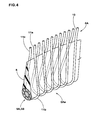
- both ends 6Ae of the carcass ply 6A are perfectly secured to the bead cores 5A and 5B as shown in Fig.4 .
- the carcass ply 6A does not have conventional turned up portions, therefore, the tire weight can be reduced accordingly.
- the carcass ply 6A does not have cut edges on which bending/compressive stress tends to concentrate, therefore, the separation failures due to cut edges are resolved, and the bead durability can be improved.
- the cord count (ends/5 cm width) of the carcass ply 6A can be determined freely in the same way as in the conventional carcass ply having turnup portions.
- the bead portions 4 are each provided with a bead apex 8 made of a hard rubber having a rubber hardness of from 50 to 98 degrees in order to reinforce the bead portions 4 and increase the bead rigidity, and thereby to improve the bead durability and steering stability.
- the bead apex 8 extends radially outwardly from the bead core 5 in a tapered manner.
- the radial height Ha of the bead apex 8 from the bead core 5 is preferably set in a range of from 5 to 70 % of the tire section height H0 from the bead base line BL in view of the steering stability and ride comfort.
- the bead apex 8 is disposed within the windings, more specifically, between the first lengthy parts 11a and second lengthy parts 11c.
- the carcass ply 6A is double-layered. But, on the radially outside of the radially outer end of the bead apexes, in other words, in the tread portion 2 and sidewall portions 3, the carcass ply 6A is single-layered.
- the first lengthy parts 11a are located axially inside the bead apexes 8
- the second lengthy part 11c are located axially outside the bead apexes 8.
- the first lengthy parts 11a are located axially inside the bead apex 8 in one of the bead portions, but axially outside the bead apex 8 in the other bead portion. Accordingly, the second lengthy part 11c are located reversely thereto.
- a cable bead core 13 as shown in Fig. 5(A) is preferably used as the bead core 5.
- the cable bead core 13 has a round cross sectional shape, and has such a structure that an annular core wire 14 is disposed in its center in the cross section, and at least one sheath layer 15 made of one ore more sheath wires 15A helically wound around the core wire 14 is provided. Therefore, the sheath layer 15 is somewhat rotatable around the core wire 14.
- Fig.5(B) shows so called tape bead core 26 formed by winding a rubber tape 29 in which a plurality of (for example five) parallel bead wires 28 are embedded along the length thereof so that the windings of the rubber tape 29 overlap one upon another in the radial direction.
- Fig.5(c) shows so called multi-winding bead core 27 formed by winding a rubber-coated bead wire 28 into multiple layers each layer including multiple windings of the bead wire 28.
- the reason for the preference of such cable bead core 13 is due to the following tire manufacturing method.
- the bead apex 8 is attached to the bead core 5 (5A, 5B) in order to form a bead-core-and-apex assembly 20.
- the two bead-core-and-apex assemblies 20 are held such that the distance between the bead cores 5A and 5B becomes substantially equal to the length of the carcass cord between the bead cores 5A and 5B in the finished pneumatic tire 1, and the bead apexes 8 are oriented sideways to confront each other.
- the carcass cord 10 is looped around the bead cores 5A and 5B to form a cylindrical assembly 21 of the carcass ply and the bead assemblies 20.
- a spool 22 of the carcass cord 10 is moved according to the path of the carcass cord 10 as shown in Fig.6 .
- an inner liner rubber 30 is applied to the inner circumferential surface of the cylindrical assembly 21.
- a thin seat of inner liner rubber 30 is wound around an expandable cylindrical drum (not shown) to form a cylindrical inner liner rubber 30 whose outer diameter is smaller than the inner diameter of the cylindrical assembly 21.
- the cylindrical inner liner rubber 30 on the drum is inserted in the cylindrical assembly 21, and the drum is expanded to adhere the inner liner rubber 30 to the inside of the cylindrical assembly 21.
- a bead rubber (not shown) defining the surface of the bead portion 4 and the like are applied, and the assembly is shaped into a toroidal shape as shown in Fig.7(D) . Therefore, as the assembly is swelled, it is necessary to decrease the distance between the bead cores 5A and 5B, and at the same time, it is necessary that the bead core 5 rotate together with the bead apex 8 so that the bead apex 8 orients radially outwards.
- tread components e.g. the belt 7, tread rubber 2G and the like are applied to the swelled crown portion 21A of the assembly 21.
- annular tread ring 25 which is an assembly of tread components, e.g. the belt 7, tread rubber 2G and the like is formed beforehand, and the tread ring 25 is placed around the crown portion 21A of the assembly 21 being swelled so that the inside of the tread ring 25 closely contacts with the swelled crown portion 21A to form a raw tire.
- the bead core 5 which is not rotatable or hard to rotate, for example, the tape bead core 26 shown in Fig.5(B) , the multi-winding bead core 27 shown in Fig.5(C) and the like may be used.
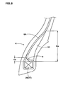
- a bead reinforcing filler 30 made of the above-mentioned hard rubber is disposed axially outside the carcass ply 6A as shown in Fig.8 .
- Such bead reinforcing filler 30 can be applied after shaped into a toroidal shape, therefore, it is not necessary to rotate the bead cores.
- the height Ha of the bead apex 8 is less than 10 mm which is insufficient for reinforcing the bead portion, therefore, the bead reinforcing filler 30 is used.
- the carcass cord 10 is coated with a topping rubber 23 before wound.
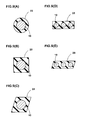
- Figs.9(A), 9(B) and 9(C) show examples in which the carcass cord 10 is covered with the topping rubber 23 so as to have a round cross sectional shape, a rectangular cross sectional shape, a diamond cross sectional shape, respectively.
- Figs.9(D) and 9(E) show examples in which a plurality of (two-ten) carcass cords 10 are laid parallel each other and covered with the topping rubber 23 in a form of a tape having a rectangular cross sectional shape, and a parallelogram cross sectional shape, respectively.
- Pneumatic tires (size 195/65R15) having the structure shown in Fig.1 were made and tested for the durability and steering stability, and the tire weight was measured. Except for the specifications shown in Table 1, the test tires had substantially same specifications.
- each test tire was run under accelerated conditions(150 % of the maximum tire load specified in JIS; 80 % of the tire pressure for the maximum tire load specified in JIS; and running speed of 80 km/h) until the tire was broken, and the running distance was obtained.
- the results are indicated in Table 1 by an index based on Ref.1 being 100, wherein the larger the value, the better the durability.
- test tires mounted on wheel rims (size 15X6JJ) and inflated to 200 kPa were attached to the four wheels of a Japanese 2000 cc FF passenger car.
- the test car was run on an asphalt road in a tire test course by a test driver, and the test driver evaluated the steering stability based on the straight running stability, lane change stability, cornering performance and ride comfort.
Landscapes
- Engineering & Computer Science (AREA)
- Mechanical Engineering (AREA)
- Tires In General (AREA)
- Tyre Moulding (AREA)
Applications Claiming Priority (1)
| Application Number | Priority Date | Filing Date | Title |
|---|---|---|---|
| JP2009234463A JP5081212B2 (ja) | 2009-10-08 | 2009-10-08 | 空気入りタイヤ |
Publications (2)
| Publication Number | Publication Date |
|---|---|
| EP2308694A1 true EP2308694A1 (de) | 2011-04-13 |
| EP2308694B1 EP2308694B1 (de) | 2012-10-03 |
Family
ID=43086486
Family Applications (1)
| Application Number | Title | Priority Date | Filing Date |
|---|---|---|---|
| EP10007871A Not-in-force EP2308694B1 (de) | 2009-10-08 | 2010-07-28 | Luftreifen |
Country Status (4)
| Country | Link |
|---|---|
| US (2) | US8590587B2 (de) |
| EP (1) | EP2308694B1 (de) |
| JP (1) | JP5081212B2 (de) |
| CN (1) | CN102029860A (de) |
Families Citing this family (13)
| Publication number | Priority date | Publication date | Assignee | Title |
|---|---|---|---|---|
| FR2891770B1 (fr) | 2005-10-06 | 2007-12-07 | Michelin Soc Tech | Procede et dispositif de mesure de pression de gonflage d'un pneumatique au moyen d'un capteur de contrainte |
| GB0601865D0 (en) * | 2006-01-30 | 2006-03-08 | Bp Chem Int Ltd | Process |
| EP3074248A4 (de) | 2013-11-27 | 2017-07-12 | Bridgestone Americas Tire Operations, LLC | Reifenkonstruktion mit einer kontinuierlichen karkassenlagenhebestruktur |
| JP5961200B2 (ja) * | 2014-02-25 | 2016-08-02 | 住友ゴム工業株式会社 | 空気入りタイヤ |
| EP2990190A1 (de) * | 2014-08-28 | 2016-03-02 | The Goodyear Tire & Rubber Company | Vorrichtung und verfahren zur herstellung von reifenlagen |
| JP6473377B2 (ja) * | 2015-04-30 | 2019-02-20 | 住友ゴム工業株式会社 | 空気入りタイヤの製造方法 |
| JP6517673B2 (ja) * | 2015-11-30 | 2019-05-22 | Toyo Tire株式会社 | 空気入りタイヤ及びそのカーカスプライ部材 |
| JP6850124B2 (ja) * | 2016-12-27 | 2021-03-31 | Toyo Tire株式会社 | 空気入りタイヤ及びそのカーカスプライ部材 |
| JP6750639B2 (ja) * | 2018-01-30 | 2020-09-02 | 住友ゴム工業株式会社 | 空気入りタイヤ |
| JP6729617B2 (ja) * | 2018-03-12 | 2020-07-22 | 住友ゴム工業株式会社 | タイヤ |
| JP6698146B1 (ja) * | 2018-12-26 | 2020-05-27 | Toyo Tire株式会社 | タイヤおよびタイヤの製造方法 |
| FR3094672B1 (fr) * | 2019-04-05 | 2021-03-12 | Michelin & Cie | Pneumatique ayant des architectures sommet et bourrelet optimisées |
| CN119682440A (zh) * | 2024-12-30 | 2025-03-25 | 哈尔滨工业大学 | 一种具有连续编织胎体帘布层的轮胎 |
Citations (3)
| Publication number | Priority date | Publication date | Assignee | Title |
|---|---|---|---|---|
| GB256290A (en) * | 1925-03-07 | 1926-08-09 | Frank Fayers Kerr | Improvements in pneumatic wheel tyres |
| DE3303595A1 (de) * | 1982-02-11 | 1983-08-25 | Janus GmbH, 4000 Düsseldorf | Guertel- oder radialreifen und verfahren und vorrichtung zu dessen herstellung |
| DE4203568A1 (de) * | 1991-02-08 | 1992-08-27 | Sumitomo Rubber Ind | Luftreifen |
Family Cites Families (17)
| Publication number | Priority date | Publication date | Assignee | Title |
|---|---|---|---|---|
| US1386072A (en) * | 1921-08-02 | Auhonso comstock pratt | ||
| US1270053A (en) * | 1917-09-27 | 1918-06-18 | Louis M Ream | Reinforcing member for tire-beads and method of making same. |
| LU38594A1 (de) * | 1959-05-12 | |||
| NL134149C (de) * | 1965-07-24 | Michelin & Cie | ||
| DE3337190A1 (de) * | 1983-10-13 | 1985-04-25 | Jonny 4000 Düsseldorf Janus | Verfahren zum herstellen von cordeinlagen fuer radialreifen und fuer derartige luftreifen geeigneter wulstring |
| US4872497A (en) * | 1984-11-26 | 1989-10-10 | The Yokohama Rubber Co., Ltd. | Pneumatic radial tire and rim combination for passenger car |
| EP0250605B1 (de) * | 1986-05-21 | 1991-07-24 | The Yokohama Rubber Co., Ltd. | Gürtelreifen für PKW |
| US4726408A (en) * | 1987-04-17 | 1988-02-23 | The Goodyear Tire & Rubber Company | Pneumatic tire bead portion structure |
| US5010938A (en) * | 1990-03-30 | 1991-04-30 | The Goodyear Tire & Rubber Company | Tire incorporating a bead ring comprising round wire disposed in the shape of a parallelogram |
| IT1241331B (it) * | 1990-12-04 | 1994-01-10 | Firestone Int Dev Spa | Metodo per la realizzazione di un componente armato tubolare di una carcassa di pneumatico di veicolo |
| JPH07149117A (ja) * | 1993-11-30 | 1995-06-13 | Toyo Tire & Rubber Co Ltd | 空気入りタイヤ |
| JPH08197908A (ja) * | 1995-01-27 | 1996-08-06 | Yokohama Rubber Co Ltd:The | 空気入りタイヤ |
| JP3113564B2 (ja) * | 1995-12-08 | 2000-12-04 | 住友ゴム工業株式会社 | 空気入りタイヤ |
| JP3232262B2 (ja) * | 1997-05-30 | 2001-11-26 | 住友ゴム工業株式会社 | 重荷重用空気入りタイヤ |
| JP3890050B2 (ja) * | 2003-12-22 | 2007-03-07 | 住友ゴム工業株式会社 | 重荷重用タイヤ |
| CN100572110C (zh) * | 2004-07-05 | 2009-12-23 | 住友电工钢线株式会社 | 环形同心扭绞胎圈帘线 |
| JP2006131001A (ja) * | 2004-11-04 | 2006-05-25 | Bridgestone Corp | 空気入りタイヤ及び空気入りタイヤ製造方法 |
-
2009
- 2009-10-08 JP JP2009234463A patent/JP5081212B2/ja not_active Expired - Fee Related
-
2010
- 2010-07-28 EP EP10007871A patent/EP2308694B1/de not_active Not-in-force
- 2010-08-09 US US12/852,985 patent/US8590587B2/en not_active Expired - Fee Related
- 2010-09-13 CN CN2010102816694A patent/CN102029860A/zh active Pending
-
2012
- 2012-10-05 US US13/646,098 patent/US20130025762A1/en not_active Abandoned
Patent Citations (3)
| Publication number | Priority date | Publication date | Assignee | Title |
|---|---|---|---|---|
| GB256290A (en) * | 1925-03-07 | 1926-08-09 | Frank Fayers Kerr | Improvements in pneumatic wheel tyres |
| DE3303595A1 (de) * | 1982-02-11 | 1983-08-25 | Janus GmbH, 4000 Düsseldorf | Guertel- oder radialreifen und verfahren und vorrichtung zu dessen herstellung |
| DE4203568A1 (de) * | 1991-02-08 | 1992-08-27 | Sumitomo Rubber Ind | Luftreifen |
Also Published As
| Publication number | Publication date |
|---|---|
| EP2308694B1 (de) | 2012-10-03 |
| US8590587B2 (en) | 2013-11-26 |
| US20110083782A1 (en) | 2011-04-14 |
| CN102029860A (zh) | 2011-04-27 |
| US20130025762A1 (en) | 2013-01-31 |
| JP5081212B2 (ja) | 2012-11-28 |
| JP2011079460A (ja) | 2011-04-21 |
Similar Documents
| Publication | Publication Date | Title |
|---|---|---|
| EP2308694B1 (de) | Luftreifen | |
| CN100393507C (zh) | 充气轮胎及其制造方法 | |
| US6053229A (en) | Pneumatic tire with specified bead filler height and method of manufacturing the same | |
| EP1671814A1 (de) | Asymmetrischer Notlaufluftreifen | |
| US20040007305A1 (en) | Pneumatic tire | |
| US11312190B2 (en) | Pneumatic tire | |
| US11260704B2 (en) | Pneumatic tire | |
| US12605972B2 (en) | Pneumatic tire | |
| EP2910392B1 (de) | Luftreifen | |
| EP2974891B1 (de) | Luftreifen | |
| CN100572107C (zh) | 具有改进的高速性能的轮胎以及制造方法 | |
| KR101067636B1 (ko) | 공기 주입 타이어 | |
| US11554615B2 (en) | Pneumatic tire | |
| US11660914B2 (en) | Pneumatic tire | |
| US20160082784A1 (en) | Pneumatic tire | |
| JP2001121917A (ja) | 空気入りラジアルタイヤ | |
| EP1792752B1 (de) | Radialluftreifen für kleinen lastwagen | |
| JP6171501B2 (ja) | 空気入りタイヤ | |
| EP3078509B1 (de) | Luftreifen | |
| US20150258862A1 (en) | Pneumatic tire and production method therefor | |
| EP2786881A2 (de) | Reifen mit Notlaufeigenschaften | |
| EP3792079B1 (de) | Schwerlastluftreifen | |
| JP5054955B2 (ja) | 航空機ラジアルタイヤ | |
| EP3900954B1 (de) | Luftreifen | |
| EP4282668B1 (de) | Luftreifen |
Legal Events
| Date | Code | Title | Description |
|---|---|---|---|
| PUAI | Public reference made under article 153(3) epc to a published international application that has entered the european phase |
Free format text: ORIGINAL CODE: 0009012 |
|
| AK | Designated contracting states |
Kind code of ref document: A1 Designated state(s): AL AT BE BG CH CY CZ DE DK EE ES FI FR GB GR HR HU IE IS IT LI LT LU LV MC MK MT NL NO PL PT RO SE SI SK SM TR |
|
| AX | Request for extension of the european patent |
Extension state: BA ME RS |
|
| 17P | Request for examination filed |
Effective date: 20111012 |
|
| GRAP | Despatch of communication of intention to grant a patent |
Free format text: ORIGINAL CODE: EPIDOSNIGR1 |
|
| GRAS | Grant fee paid |
Free format text: ORIGINAL CODE: EPIDOSNIGR3 |
|
| GRAA | (expected) grant |
Free format text: ORIGINAL CODE: 0009210 |
|
| AK | Designated contracting states |
Kind code of ref document: B1 Designated state(s): AL AT BE BG CH CY CZ DE DK EE ES FI FR GB GR HR HU IE IS IT LI LT LU LV MC MK MT NL NO PL PT RO SE SI SK SM TR |
|
| REG | Reference to a national code |
Ref country code: GB Ref legal event code: FG4D |
|
| REG | Reference to a national code |
Ref country code: AT Ref legal event code: REF Ref document number: 577798 Country of ref document: AT Kind code of ref document: T Effective date: 20121015 Ref country code: CH Ref legal event code: EP |
|
| REG | Reference to a national code |
Ref country code: IE Ref legal event code: FG4D |
|
| REG | Reference to a national code |
Ref country code: DE Ref legal event code: R096 Ref document number: 602010003006 Country of ref document: DE Effective date: 20121129 |
|
| REG | Reference to a national code |
Ref country code: AT Ref legal event code: MK05 Ref document number: 577798 Country of ref document: AT Kind code of ref document: T Effective date: 20121003 |
|
| PG25 | Lapsed in a contracting state [announced via postgrant information from national office to epo] |
Ref country code: SI Free format text: LAPSE BECAUSE OF FAILURE TO SUBMIT A TRANSLATION OF THE DESCRIPTION OR TO PAY THE FEE WITHIN THE PRESCRIBED TIME-LIMIT Effective date: 20121003 |
|
| REG | Reference to a national code |
Ref country code: NL Ref legal event code: VDEP Effective date: 20121003 |
|
| REG | Reference to a national code |
Ref country code: LT Ref legal event code: MG4D |
|
| PG25 | Lapsed in a contracting state [announced via postgrant information from national office to epo] |
Ref country code: FI Free format text: LAPSE BECAUSE OF FAILURE TO SUBMIT A TRANSLATION OF THE DESCRIPTION OR TO PAY THE FEE WITHIN THE PRESCRIBED TIME-LIMIT Effective date: 20121003 Ref country code: IS Free format text: LAPSE BECAUSE OF FAILURE TO SUBMIT A TRANSLATION OF THE DESCRIPTION OR TO PAY THE FEE WITHIN THE PRESCRIBED TIME-LIMIT Effective date: 20130203 Ref country code: HR Free format text: LAPSE BECAUSE OF FAILURE TO SUBMIT A TRANSLATION OF THE DESCRIPTION OR TO PAY THE FEE WITHIN THE PRESCRIBED TIME-LIMIT Effective date: 20121003 Ref country code: LT Free format text: LAPSE BECAUSE OF FAILURE TO SUBMIT A TRANSLATION OF THE DESCRIPTION OR TO PAY THE FEE WITHIN THE PRESCRIBED TIME-LIMIT Effective date: 20121003 Ref country code: NO Free format text: LAPSE BECAUSE OF FAILURE TO SUBMIT A TRANSLATION OF THE DESCRIPTION OR TO PAY THE FEE WITHIN THE PRESCRIBED TIME-LIMIT Effective date: 20130103 Ref country code: SE Free format text: LAPSE BECAUSE OF FAILURE TO SUBMIT A TRANSLATION OF THE DESCRIPTION OR TO PAY THE FEE WITHIN THE PRESCRIBED TIME-LIMIT Effective date: 20121003 Ref country code: ES Free format text: LAPSE BECAUSE OF FAILURE TO SUBMIT A TRANSLATION OF THE DESCRIPTION OR TO PAY THE FEE WITHIN THE PRESCRIBED TIME-LIMIT Effective date: 20130114 Ref country code: NL Free format text: LAPSE BECAUSE OF FAILURE TO SUBMIT A TRANSLATION OF THE DESCRIPTION OR TO PAY THE FEE WITHIN THE PRESCRIBED TIME-LIMIT Effective date: 20121003 |
|
| PG25 | Lapsed in a contracting state [announced via postgrant information from national office to epo] |
Ref country code: LV Free format text: LAPSE BECAUSE OF FAILURE TO SUBMIT A TRANSLATION OF THE DESCRIPTION OR TO PAY THE FEE WITHIN THE PRESCRIBED TIME-LIMIT Effective date: 20121003 Ref country code: BE Free format text: LAPSE BECAUSE OF FAILURE TO SUBMIT A TRANSLATION OF THE DESCRIPTION OR TO PAY THE FEE WITHIN THE PRESCRIBED TIME-LIMIT Effective date: 20121003 Ref country code: PL Free format text: LAPSE BECAUSE OF FAILURE TO SUBMIT A TRANSLATION OF THE DESCRIPTION OR TO PAY THE FEE WITHIN THE PRESCRIBED TIME-LIMIT Effective date: 20121003 Ref country code: GR Free format text: LAPSE BECAUSE OF FAILURE TO SUBMIT A TRANSLATION OF THE DESCRIPTION OR TO PAY THE FEE WITHIN THE PRESCRIBED TIME-LIMIT Effective date: 20130104 Ref country code: PT Free format text: LAPSE BECAUSE OF FAILURE TO SUBMIT A TRANSLATION OF THE DESCRIPTION OR TO PAY THE FEE WITHIN THE PRESCRIBED TIME-LIMIT Effective date: 20130204 |
|
| PG25 | Lapsed in a contracting state [announced via postgrant information from national office to epo] |
Ref country code: AT Free format text: LAPSE BECAUSE OF FAILURE TO SUBMIT A TRANSLATION OF THE DESCRIPTION OR TO PAY THE FEE WITHIN THE PRESCRIBED TIME-LIMIT Effective date: 20121003 |
|
| PG25 | Lapsed in a contracting state [announced via postgrant information from national office to epo] |
Ref country code: DK Free format text: LAPSE BECAUSE OF FAILURE TO SUBMIT A TRANSLATION OF THE DESCRIPTION OR TO PAY THE FEE WITHIN THE PRESCRIBED TIME-LIMIT Effective date: 20121003 Ref country code: EE Free format text: LAPSE BECAUSE OF FAILURE TO SUBMIT A TRANSLATION OF THE DESCRIPTION OR TO PAY THE FEE WITHIN THE PRESCRIBED TIME-LIMIT Effective date: 20121003 Ref country code: CZ Free format text: LAPSE BECAUSE OF FAILURE TO SUBMIT A TRANSLATION OF THE DESCRIPTION OR TO PAY THE FEE WITHIN THE PRESCRIBED TIME-LIMIT Effective date: 20121003 Ref country code: SK Free format text: LAPSE BECAUSE OF FAILURE TO SUBMIT A TRANSLATION OF THE DESCRIPTION OR TO PAY THE FEE WITHIN THE PRESCRIBED TIME-LIMIT Effective date: 20121003 Ref country code: BG Free format text: LAPSE BECAUSE OF FAILURE TO SUBMIT A TRANSLATION OF THE DESCRIPTION OR TO PAY THE FEE WITHIN THE PRESCRIBED TIME-LIMIT Effective date: 20130103 |
|
| PLBE | No opposition filed within time limit |
Free format text: ORIGINAL CODE: 0009261 |
|
| STAA | Information on the status of an ep patent application or granted ep patent |
Free format text: STATUS: NO OPPOSITION FILED WITHIN TIME LIMIT |
|
| PG25 | Lapsed in a contracting state [announced via postgrant information from national office to epo] |
Ref country code: IT Free format text: LAPSE BECAUSE OF FAILURE TO SUBMIT A TRANSLATION OF THE DESCRIPTION OR TO PAY THE FEE WITHIN THE PRESCRIBED TIME-LIMIT Effective date: 20121003 Ref country code: RO Free format text: LAPSE BECAUSE OF FAILURE TO SUBMIT A TRANSLATION OF THE DESCRIPTION OR TO PAY THE FEE WITHIN THE PRESCRIBED TIME-LIMIT Effective date: 20121003 |
|
| 26N | No opposition filed |
Effective date: 20130704 |
|
| REG | Reference to a national code |
Ref country code: DE Ref legal event code: R097 Ref document number: 602010003006 Country of ref document: DE Effective date: 20130704 |
|
| PG25 | Lapsed in a contracting state [announced via postgrant information from national office to epo] |
Ref country code: CY Free format text: LAPSE BECAUSE OF FAILURE TO SUBMIT A TRANSLATION OF THE DESCRIPTION OR TO PAY THE FEE WITHIN THE PRESCRIBED TIME-LIMIT Effective date: 20121003 |
|
| PG25 | Lapsed in a contracting state [announced via postgrant information from national office to epo] |
Ref country code: MC Free format text: LAPSE BECAUSE OF FAILURE TO SUBMIT A TRANSLATION OF THE DESCRIPTION OR TO PAY THE FEE WITHIN THE PRESCRIBED TIME-LIMIT Effective date: 20121003 |
|
| REG | Reference to a national code |
Ref country code: IE Ref legal event code: MM4A |
|
| PG25 | Lapsed in a contracting state [announced via postgrant information from national office to epo] |
Ref country code: IE Free format text: LAPSE BECAUSE OF NON-PAYMENT OF DUE FEES Effective date: 20130728 |
|
| REG | Reference to a national code |
Ref country code: CH Ref legal event code: PL |
|
| GBPC | Gb: european patent ceased through non-payment of renewal fee |
Effective date: 20140728 |
|
| PG25 | Lapsed in a contracting state [announced via postgrant information from national office to epo] |
Ref country code: CH Free format text: LAPSE BECAUSE OF NON-PAYMENT OF DUE FEES Effective date: 20140731 Ref country code: LI Free format text: LAPSE BECAUSE OF NON-PAYMENT OF DUE FEES Effective date: 20140731 |
|
| PG25 | Lapsed in a contracting state [announced via postgrant information from national office to epo] |
Ref country code: GB Free format text: LAPSE BECAUSE OF NON-PAYMENT OF DUE FEES Effective date: 20140728 Ref country code: SM Free format text: LAPSE BECAUSE OF FAILURE TO SUBMIT A TRANSLATION OF THE DESCRIPTION OR TO PAY THE FEE WITHIN THE PRESCRIBED TIME-LIMIT Effective date: 20121003 |
|
| PG25 | Lapsed in a contracting state [announced via postgrant information from national office to epo] |
Ref country code: MT Free format text: LAPSE BECAUSE OF FAILURE TO SUBMIT A TRANSLATION OF THE DESCRIPTION OR TO PAY THE FEE WITHIN THE PRESCRIBED TIME-LIMIT Effective date: 20121003 Ref country code: TR Free format text: LAPSE BECAUSE OF FAILURE TO SUBMIT A TRANSLATION OF THE DESCRIPTION OR TO PAY THE FEE WITHIN THE PRESCRIBED TIME-LIMIT Effective date: 20121003 |
|
| PG25 | Lapsed in a contracting state [announced via postgrant information from national office to epo] |
Ref country code: HU Free format text: LAPSE BECAUSE OF FAILURE TO SUBMIT A TRANSLATION OF THE DESCRIPTION OR TO PAY THE FEE WITHIN THE PRESCRIBED TIME-LIMIT; INVALID AB INITIO Effective date: 20100728 Ref country code: LU Free format text: LAPSE BECAUSE OF NON-PAYMENT OF DUE FEES Effective date: 20130728 Ref country code: MK Free format text: LAPSE BECAUSE OF FAILURE TO SUBMIT A TRANSLATION OF THE DESCRIPTION OR TO PAY THE FEE WITHIN THE PRESCRIBED TIME-LIMIT Effective date: 20121003 |
|
| REG | Reference to a national code |
Ref country code: FR Ref legal event code: PLFP Year of fee payment: 7 |
|
| REG | Reference to a national code |
Ref country code: FR Ref legal event code: PLFP Year of fee payment: 8 |
|
| PGFP | Annual fee paid to national office [announced via postgrant information from national office to epo] |
Ref country code: FR Payment date: 20170613 Year of fee payment: 8 |
|
| PGFP | Annual fee paid to national office [announced via postgrant information from national office to epo] |
Ref country code: DE Payment date: 20170725 Year of fee payment: 8 |
|
| PG25 | Lapsed in a contracting state [announced via postgrant information from national office to epo] |
Ref country code: AL Free format text: LAPSE BECAUSE OF FAILURE TO SUBMIT A TRANSLATION OF THE DESCRIPTION OR TO PAY THE FEE WITHIN THE PRESCRIBED TIME-LIMIT Effective date: 20121003 |
|
| REG | Reference to a national code |
Ref country code: DE Ref legal event code: R119 Ref document number: 602010003006 Country of ref document: DE |
|
| PG25 | Lapsed in a contracting state [announced via postgrant information from national office to epo] |
Ref country code: DE Free format text: LAPSE BECAUSE OF NON-PAYMENT OF DUE FEES Effective date: 20190201 Ref country code: FR Free format text: LAPSE BECAUSE OF NON-PAYMENT OF DUE FEES Effective date: 20180731 |