EP2308701A1 - Achsenaufhängungssystem für Fahrzeughinterachsen und zusätzliche Achsen - Google Patents
Achsenaufhängungssystem für Fahrzeughinterachsen und zusätzliche Achsen Download PDFInfo
- Publication number
- EP2308701A1 EP2308701A1 EP09172438A EP09172438A EP2308701A1 EP 2308701 A1 EP2308701 A1 EP 2308701A1 EP 09172438 A EP09172438 A EP 09172438A EP 09172438 A EP09172438 A EP 09172438A EP 2308701 A1 EP2308701 A1 EP 2308701A1
- Authority
- EP
- European Patent Office
- Prior art keywords
- axle
- suspension
- additional
- vehicle
- control arm
- Prior art date
- Legal status (The legal status is an assumption and is not a legal conclusion. Google has not performed a legal analysis and makes no representation as to the accuracy of the status listed.)
- Granted
Links
Images
Classifications
-
- B—PERFORMING OPERATIONS; TRANSPORTING
- B60—VEHICLES IN GENERAL
- B60G—VEHICLE SUSPENSION ARRANGEMENTS
- B60G9/00—Resilient suspensions of a rigid axle or axle housing for two or more wheels
- B60G9/003—Resilient suspensions of a rigid axle or axle housing for two or more wheels the axle being rigidly connected to a trailing guiding device
-
- B—PERFORMING OPERATIONS; TRANSPORTING
- B60—VEHICLES IN GENERAL
- B60G—VEHICLE SUSPENSION ARRANGEMENTS
- B60G11/00—Resilient suspensions characterised by arrangement, location or kind of springs
- B60G11/26—Resilient suspensions characterised by arrangement, location or kind of springs having fluid springs only, e.g. hydropneumatic springs
- B60G11/28—Resilient suspensions characterised by arrangement, location or kind of springs having fluid springs only, e.g. hydropneumatic springs characterised by means specially adapted for attaching the spring to axle or sprung part of the vehicle
-
- B—PERFORMING OPERATIONS; TRANSPORTING
- B60—VEHICLES IN GENERAL
- B60G—VEHICLE SUSPENSION ARRANGEMENTS
- B60G7/00—Pivoted suspension arms; Accessories thereof
- B60G7/02—Attaching arms to sprung part of vehicle
-
- B—PERFORMING OPERATIONS; TRANSPORTING
- B62—LAND VEHICLES FOR TRAVELLING OTHERWISE THAN ON RAILS
- B62D—MOTOR VEHICLES; TRAILERS
- B62D21/00—Understructures, i.e. chassis frame on which a vehicle body may be mounted
- B62D21/02—Understructures, i.e. chassis frame on which a vehicle body may be mounted comprising longitudinally or transversely arranged frame members
-
- B—PERFORMING OPERATIONS; TRANSPORTING
- B62—LAND VEHICLES FOR TRAVELLING OTHERWISE THAN ON RAILS
- B62D—MOTOR VEHICLES; TRAILERS
- B62D61/00—Motor vehicles or trailers, characterised by the arrangement or number of wheels, not otherwise provided for, e.g. four wheels in diamond pattern
- B62D61/12—Motor vehicles or trailers, characterised by the arrangement or number of wheels, not otherwise provided for, e.g. four wheels in diamond pattern with variable number of ground engaging wheels, e.g. with some wheels arranged higher than others, or with retractable wheels
- B62D61/125—Motor vehicles or trailers, characterised by the arrangement or number of wheels, not otherwise provided for, e.g. four wheels in diamond pattern with variable number of ground engaging wheels, e.g. with some wheels arranged higher than others, or with retractable wheels the retractable wheel being a part of a set of tandem wheels
-
- B—PERFORMING OPERATIONS; TRANSPORTING
- B60—VEHICLES IN GENERAL
- B60G—VEHICLE SUSPENSION ARRANGEMENTS
- B60G2200/00—Indexing codes relating to suspension types
- B60G2200/30—Rigid axle suspensions
-
- B—PERFORMING OPERATIONS; TRANSPORTING
- B60—VEHICLES IN GENERAL
- B60G—VEHICLE SUSPENSION ARRANGEMENTS
- B60G2200/00—Indexing codes relating to suspension types
- B60G2200/30—Rigid axle suspensions
- B60G2200/314—Rigid axle suspensions with longitudinally arranged arms articulated on the axle
-
- B—PERFORMING OPERATIONS; TRANSPORTING
- B60—VEHICLES IN GENERAL
- B60G—VEHICLE SUSPENSION ARRANGEMENTS
- B60G2200/00—Indexing codes relating to suspension types
- B60G2200/30—Rigid axle suspensions
- B60G2200/314—Rigid axle suspensions with longitudinally arranged arms articulated on the axle
- B60G2200/315—Rigid axle suspensions with longitudinally arranged arms articulated on the axle at least one of the arms having an A or V shape
-
- B—PERFORMING OPERATIONS; TRANSPORTING
- B60—VEHICLES IN GENERAL
- B60G—VEHICLE SUSPENSION ARRANGEMENTS
- B60G2200/00—Indexing codes relating to suspension types
- B60G2200/40—Indexing codes relating to the wheels in the suspensions
- B60G2200/42—Driven wheels or dead axles
-
- B—PERFORMING OPERATIONS; TRANSPORTING
- B60—VEHICLES IN GENERAL
- B60G—VEHICLE SUSPENSION ARRANGEMENTS
- B60G2200/00—Indexing codes relating to suspension types
- B60G2200/40—Indexing codes relating to the wheels in the suspensions
- B60G2200/422—Driving wheels or live axles
-
- B—PERFORMING OPERATIONS; TRANSPORTING
- B60—VEHICLES IN GENERAL
- B60G—VEHICLE SUSPENSION ARRANGEMENTS
- B60G2202/00—Indexing codes relating to the type of spring, damper or actuator
- B60G2202/10—Type of spring
- B60G2202/15—Fluid spring
- B60G2202/152—Pneumatic spring
-
- B—PERFORMING OPERATIONS; TRANSPORTING
- B60—VEHICLES IN GENERAL
- B60G—VEHICLE SUSPENSION ARRANGEMENTS
- B60G2202/00—Indexing codes relating to the type of spring, damper or actuator
- B60G2202/40—Type of actuator
- B60G2202/41—Fluid actuator
-
- B—PERFORMING OPERATIONS; TRANSPORTING
- B60—VEHICLES IN GENERAL
- B60G—VEHICLE SUSPENSION ARRANGEMENTS
- B60G2204/00—Indexing codes related to suspensions per se or to auxiliary parts
- B60G2204/10—Mounting of suspension elements
- B60G2204/12—Mounting of springs or dampers
- B60G2204/126—Mounting of pneumatic springs
-
- B—PERFORMING OPERATIONS; TRANSPORTING
- B60—VEHICLES IN GENERAL
- B60G—VEHICLE SUSPENSION ARRANGEMENTS
- B60G2204/00—Indexing codes related to suspensions per se or to auxiliary parts
- B60G2204/10—Mounting of suspension elements
- B60G2204/12—Mounting of springs or dampers
- B60G2204/128—Damper mount on vehicle body or chassis
-
- B—PERFORMING OPERATIONS; TRANSPORTING
- B60—VEHICLES IN GENERAL
- B60G—VEHICLE SUSPENSION ARRANGEMENTS
- B60G2204/00—Indexing codes related to suspensions per se or to auxiliary parts
- B60G2204/10—Mounting of suspension elements
- B60G2204/14—Mounting of suspension arms
- B60G2204/143—Mounting of suspension arms on the vehicle body or chassis
-
- B—PERFORMING OPERATIONS; TRANSPORTING
- B60—VEHICLES IN GENERAL
- B60G—VEHICLE SUSPENSION ARRANGEMENTS
- B60G2204/00—Indexing codes related to suspensions per se or to auxiliary parts
- B60G2204/40—Auxiliary suspension parts; Adjustment of suspensions
- B60G2204/47—Means for retracting the suspension
- B60G2204/4702—Means for retracting the suspension pneumatically
-
- B—PERFORMING OPERATIONS; TRANSPORTING
- B60—VEHICLES IN GENERAL
- B60G—VEHICLE SUSPENSION ARRANGEMENTS
- B60G2206/00—Indexing codes related to the manufacturing of suspensions: constructional features, the materials used, procedures or tools
- B60G2206/01—Constructional features of suspension elements, e.g. arms, dampers, springs
- B60G2206/10—Constructional features of arms
- B60G2206/11—Constructional features of arms the arm being a radius or track or torque or steering rod or stabiliser end link
-
- B—PERFORMING OPERATIONS; TRANSPORTING
- B60—VEHICLES IN GENERAL
- B60G—VEHICLE SUSPENSION ARRANGEMENTS
- B60G2206/00—Indexing codes related to the manufacturing of suspensions: constructional features, the materials used, procedures or tools
- B60G2206/01—Constructional features of suspension elements, e.g. arms, dampers, springs
- B60G2206/10—Constructional features of arms
- B60G2206/15—Constructional features of arms the arm being resilient
-
- B—PERFORMING OPERATIONS; TRANSPORTING
- B60—VEHICLES IN GENERAL
- B60G—VEHICLE SUSPENSION ARRANGEMENTS
- B60G2206/00—Indexing codes related to the manufacturing of suspensions: constructional features, the materials used, procedures or tools
- B60G2206/01—Constructional features of suspension elements, e.g. arms, dampers, springs
- B60G2206/60—Subframe construction
- B60G2206/601—Hanger bracket
-
- B—PERFORMING OPERATIONS; TRANSPORTING
- B60—VEHICLES IN GENERAL
- B60G—VEHICLE SUSPENSION ARRANGEMENTS
- B60G2206/00—Indexing codes related to the manufacturing of suspensions: constructional features, the materials used, procedures or tools
- B60G2206/01—Constructional features of suspension elements, e.g. arms, dampers, springs
- B60G2206/60—Subframe construction
- B60G2206/604—Subframe construction with two parallel beams connected by cross members
-
- B—PERFORMING OPERATIONS; TRANSPORTING
- B60—VEHICLES IN GENERAL
- B60G—VEHICLE SUSPENSION ARRANGEMENTS
- B60G2300/00—Indexing codes relating to the type of vehicle
- B60G2300/02—Trucks; Load vehicles
- B60G2300/026—Heavy duty trucks
-
- B—PERFORMING OPERATIONS; TRANSPORTING
- B60—VEHICLES IN GENERAL
- B60G—VEHICLE SUSPENSION ARRANGEMENTS
- B60G2300/00—Indexing codes relating to the type of vehicle
- B60G2300/02—Trucks; Load vehicles
- B60G2300/026—Heavy duty trucks
- B60G2300/0262—Multi-axle trucks
Definitions
- the present invention concerns an axle suspension system for a driven rear axle of a vehicle, especially a heavy goods vehicle, and an additional axle disposed in front of the latter, as per the preamble of claim 1.
- Axle suspension systems for vehicles already exist in many different embodiments.
- a suspension sword is disposed on each side of the vehicle, said suspension swording extending in front of the rear axle downward from the vehicle chassis to provide a coupling point for a longitudinal control arm which connects the rear axle with the suspension sword.
- Guidance in the longitudinal direction is provided via the longitudinal control arm during the outward and inward spring deflections of the rear axle.
- Other components of the rear axle suspension include devices for shock absorption and other suspension constructions for guidance purposes, as are generally found in the field of vehicle construction.
- suspension systems are known of for a non-driven additional axle disposed in front of the driven rear axle in the direction of travel of the vehicle.
- These additional axle suspensions also comprise longitudinal control arms on the vehicle sides, each of which is connected at one end to the additional axle and, at the other end, to the vehicle chassis.
- the longitudinal control arm provides the lateral guidance for the additional axle.
- this longitudinal control arm extends forwards in the direction of the vehicle to a coupling point on the vehicle chassis, or to a bracket mounted on the latter.
- the forward-extending longitudinal control arm of the additional axle suspension occupies a relatively large amount of space in the vehicle undermount, as do the construction parts attached to it, such as a bracket for connecting the end of the longitudinal control arm to the vehicle chassis. This is particularly problematic in relation to chassis constructions which widen towards the front and have offset chassis longitudinal supports, as the task of connecting the forward-pointing longitudinal control arm is difficult in this case.
- the entire axle suspension system, including the rear axle suspension and the additional axle suspension, is a relatively large and complex construction in the vehicle's longitudinal direction.
- the task of this invention is therefore to simplify the axle suspension system of the above type, and to design it in a more compact fashion so that the required construction parts can be accommodated without problem in the vehicle undermount in a restricted space.
- the longitudinal control arm of the additional suspension is contrived so that it extends rearwards from the additional axle to the suspension sword of the rear axle suspension. It is flexibly connected to this suspension sword by means of a corresponding articulated connection.
- axle suspension system uses the suspension sword to connect the longitudinal control arm of the additional axle suspension such that this latter is guided laterally.
- the additional axle suspension no longer has any parts extending from the additional axle to the front chassis section.
- the additional axle can, for example, be disposed right up against a laterally expanding portion of the vehicle chassis with offset chassis longitudinal supports.
- the entire arrangement of the axle suspension system is more compact and requires fewer parts than the prior art axle suspensions in which the rear axle and additional axle suspensions are independent of each other.
- the coupling point of the longitudinal control arm of the additional axle suspension is positioned higher up the suspension sword than the coupling point of the longitudinal control arm of the rear axle suspension.
- the suspension sword has at least two articulated receiving elements disposed one above the other for alternatively receiving the end of the longitudinal control bar of the additional axle suspension.
- This embodiment therefore allows one to choose the height at which the longitudinal control arm of the additional axle suspension is attached to the suspension sword, depending on the height of the vehicle undermount and the circumstances in relation to a raisably suspended additional axle or similar.
- the longitudinal control arm of the additional axle suspension is preferably contrived as a suspension spring.
- the advantage of using a suspension spring is that it is better able to absorb the lateral forces occurring along the axle thanks to its elastic properties.
- the suspension spring of the additional axle suspension comprises two leaf springs disposed above each other, in parallel.
- the additional axle suspension comprises means to lift the additional axle relative to the vehicle chassis.
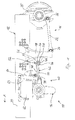
- the axle suspension system 10 shown in Fig. 1 serves to suspend a driven rear axle and an additional axle disposed in front of it in the direction of travel, of a vehicle whose vehicle chassis is designated in general by reference 12.
- the direction of travel is indicated in this figure by an arrow A (towards the left).
- Additional axle 14 is an offset axle which, in its mid portion underneath vehicle chassis 12, provides space for the drive shaft (not shown in more detail) to pass through to the rear axle.
- Rear axle suspension 16 comprises, on each side of the vehicle, a suspension sword 18 which is laterally connected by its upper end to a chassis longitudinal support 20 and extends downwards from vehicle chassis 12.
- a longitudinal control arm 22 is pivotally connected to suspension sword 18 via a joint element 24.
- Longitudinal control arm 22 extends from suspension sword 18 contrary to the direction of travel A, towards the rear, up to rear axle 25.
- the rear end 26, which is depicted freely in Fig. 1 , of longitudinal control arm 22 is connected to rear axle 25.
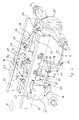
- FIG. 2 Another part of rear axle suspension 16 is formed by a triangular support 28 ( Fig. 2 ).
- the forward-pointing ends 36 of arms 32,34 are connected on the inside to longitudinal supports 20 of chassis 12.
- a cross-strut 38 of chassis 12 is positioned to provide stabilisation.
- Additional axle suspension 40 comprises, on each side of the vehicle, a suspension spring 42, which is rigidly connected to additional axle 14 by its front end in relation to the direction of travel A, and to suspension sword 18 by its rear end 44.
- the connection is provided by a joint element 46 disposed at the rear end 44 of suspension spring 42.
- the suspension springs 42 of additional axle suspension 40 are formed by two parallel leaf springs 48,50 which, one positioned above the other, start out from a fixed point of attachment on additional axle 14 and run rearward to converge at a spring eye 52 which forms part of joint element 46.
- the other part is formed by a pin which is inserted in a hole 54 contrived in a forward-pointing flange 56 of suspension sword 18.
- a second hole 58 is provided immediately underneath the first hole 54 in flange 56.
- the two holes 54,58 form two alternative joint receiving elements, disposed one above the other, for receiving the end 44 of suspension spring 42.
- spring eye 46 may be suspended by a pin in either upper hole 54 or lower hole 58.
- a clamping plate 60 (see Fig. 2 ).
- a supporting bellows 62 whose top side rests against a bracket 63 which is flange-mounted to the side of chassis longitudinal support 20.
- a shock absorber 64 is disposed behind supporting bellows 62, and is pivotally connected by its upper end to bracket 63 and by its lower end to additional axle 14.
- Additional axle suspension 40 further comprises means for lifting additional axle 14 relative to vehicle chassis 12.
- These means comprise air bellows 68 disposed in the middle of vehicle chassis 12, whose underside rests on a chassis cross-strut 70. Resting on air bellows 68 there is a lever 72, which is pivotally connected, by an end 74 pointing forwards in the direction of travel of vehicle A, to another chassis cross-strut 76. When air bellows 68 rise or fall, the rear end of lever 72 is pivoted upwards or downwards around the coupling point on the front chassis cross-strut 76. This provides lateral stabilisation for the upwards and downwards movement of air bellows 68.
- suspension springs 42 of additional axle suspension 40 also complete a pivoting movement around joint elements 46 on suspension swords 18. This also takes place when additional axle 14 undergoes inward spring deflection.
- suspension swords 18 of the rear axle suspension also provide an attachment element for suspension springs 42 of the additional axle suspension, which is disposed in front of rear axle 25 relative to the direction of travel A.
- a joint axle suspension system 10 is formed for the rear axle and additional axle 14.
- additional axle suspension 40 can be disposed relatively close to other assemblies in the vehicle undermount, or close to an offset portion of chassis longitudinal supports 20 for the purpose of widening vehicle chassis 12.
Landscapes
- Engineering & Computer Science (AREA)
- Mechanical Engineering (AREA)
- Chemical & Material Sciences (AREA)
- Combustion & Propulsion (AREA)
- Transportation (AREA)
- Vehicle Body Suspensions (AREA)
Priority Applications (3)
| Application Number | Priority Date | Filing Date | Title |
|---|---|---|---|
| ES09172438T ES2381152T3 (es) | 2009-10-07 | 2009-10-07 | Sistema de suspensión de eje para un eje trasero de vehículo y eje adicional |
| AT09172438T ATE542687T1 (de) | 2009-10-07 | 2009-10-07 | Achsenaufhängungssystem für fahrzeughinterachsen und zusätzliche achsen |
| EP09172438A EP2308701B1 (de) | 2009-10-07 | 2009-10-07 | Achsenaufhängungssystem für Fahrzeughinterachsen und zusätzliche Achsen |
Applications Claiming Priority (1)
| Application Number | Priority Date | Filing Date | Title |
|---|---|---|---|
| EP09172438A EP2308701B1 (de) | 2009-10-07 | 2009-10-07 | Achsenaufhängungssystem für Fahrzeughinterachsen und zusätzliche Achsen |
Publications (2)
| Publication Number | Publication Date |
|---|---|
| EP2308701A1 true EP2308701A1 (de) | 2011-04-13 |
| EP2308701B1 EP2308701B1 (de) | 2012-01-25 |
Family
ID=41728163
Family Applications (1)
| Application Number | Title | Priority Date | Filing Date |
|---|---|---|---|
| EP09172438A Active EP2308701B1 (de) | 2009-10-07 | 2009-10-07 | Achsenaufhängungssystem für Fahrzeughinterachsen und zusätzliche Achsen |
Country Status (3)
| Country | Link |
|---|---|
| EP (1) | EP2308701B1 (de) |
| AT (1) | ATE542687T1 (de) |
| ES (1) | ES2381152T3 (de) |
Cited By (1)
| Publication number | Priority date | Publication date | Assignee | Title |
|---|---|---|---|---|
| EP2946991A1 (de) * | 2014-05-21 | 2015-11-25 | ZF Friedrichshafen AG | Anhebevorrichtung für eine fahrzeugachse eines fahrzeugs |
Citations (7)
| Publication number | Priority date | Publication date | Assignee | Title |
|---|---|---|---|---|
| FR2496015A1 (fr) | 1980-12-11 | 1982-06-18 | Mossbauer Sohne | Groupe d'essieux a deux essieux au moins, en particulier pour remorques a plusieurs essieux de camions semi-remorques |
| US4530515A (en) * | 1983-11-09 | 1985-07-23 | Raidel John E | Dual stub axle air spring suspension with high-axle hydraulic lift |
| US4756550A (en) * | 1987-01-27 | 1988-07-12 | Raidel John E | Suspension assembly with compound parallelogram |
| EP0416310A1 (de) * | 1989-09-07 | 1991-03-13 | MAN Nutzfahrzeuge Aktiengesellschaft | Anhebbares Doppelachsaggregat |
| US20020067017A1 (en) | 2000-12-06 | 2002-06-06 | Keeler Michael J. | Vehicle suspension assembly |
| US20040164511A1 (en) * | 2003-02-26 | 2004-08-26 | Gottschalk Michael J. | Independent paddle lift axle suspension system |
| US20040232646A1 (en) * | 2000-11-27 | 2004-11-25 | Peters Scott R | Vehicle suspension system |
-
2009
- 2009-10-07 AT AT09172438T patent/ATE542687T1/de active
- 2009-10-07 ES ES09172438T patent/ES2381152T3/es active Active
- 2009-10-07 EP EP09172438A patent/EP2308701B1/de active Active
Patent Citations (7)
| Publication number | Priority date | Publication date | Assignee | Title |
|---|---|---|---|---|
| FR2496015A1 (fr) | 1980-12-11 | 1982-06-18 | Mossbauer Sohne | Groupe d'essieux a deux essieux au moins, en particulier pour remorques a plusieurs essieux de camions semi-remorques |
| US4530515A (en) * | 1983-11-09 | 1985-07-23 | Raidel John E | Dual stub axle air spring suspension with high-axle hydraulic lift |
| US4756550A (en) * | 1987-01-27 | 1988-07-12 | Raidel John E | Suspension assembly with compound parallelogram |
| EP0416310A1 (de) * | 1989-09-07 | 1991-03-13 | MAN Nutzfahrzeuge Aktiengesellschaft | Anhebbares Doppelachsaggregat |
| US20040232646A1 (en) * | 2000-11-27 | 2004-11-25 | Peters Scott R | Vehicle suspension system |
| US20020067017A1 (en) | 2000-12-06 | 2002-06-06 | Keeler Michael J. | Vehicle suspension assembly |
| US20040164511A1 (en) * | 2003-02-26 | 2004-08-26 | Gottschalk Michael J. | Independent paddle lift axle suspension system |
Cited By (1)
| Publication number | Priority date | Publication date | Assignee | Title |
|---|---|---|---|---|
| EP2946991A1 (de) * | 2014-05-21 | 2015-11-25 | ZF Friedrichshafen AG | Anhebevorrichtung für eine fahrzeugachse eines fahrzeugs |
Also Published As
| Publication number | Publication date |
|---|---|
| ES2381152T3 (es) | 2012-05-23 |
| ATE542687T1 (de) | 2012-02-15 |
| EP2308701B1 (de) | 2012-01-25 |
Similar Documents
| Publication | Publication Date | Title |
|---|---|---|
| EP2247455B1 (de) | Fahrzeugaufhängungsanordnung mit eigener geometrie | |
| US6808191B1 (en) | Axle suspension for rigid axles of vehicles | |
| US20150298521A1 (en) | Stabilizer arrangement for a wheel suspension of motor vehicles | |
| US4053171A (en) | Spring suspension arrangement for off-road vehicles | |
| NZ539740A (en) | Shackle assembly | |
| EP3121036B1 (de) | Pneumatische achsenaufhängung für eine hinterachse eines fahrzeugs | |
| CN108025610B (zh) | 用于车辆的后车轴的气动车轴悬挂系统 | |
| EP2161146B1 (de) | Pneumatische Achsenaufhängung für Motorfahrzeug | |
| CN110997356B (zh) | 具有布置在中央的驱动单元的车轴 | |
| CN201951198U (zh) | 汽车四连杆后悬架 | |
| US7500687B2 (en) | Vehicle suspension systems | |
| US7178824B2 (en) | Walking beam trailer suspension slider | |
| EP0997328A1 (de) | Aufhängungssystem mit einer starren Pendelachse, insbesondere für Schlepper | |
| EP2308701B1 (de) | Achsenaufhängungssystem für Fahrzeughinterachsen und zusätzliche Achsen | |
| NL2013397B1 (nl) | Onafhankelijke wielophanging met luchtvering voor een oplegger en opleggers daarmee uitgerust. | |
| EP2308745B1 (de) | Hebevorrichtung für zusätzliche Achsen von Fahrzeugen | |
| JP2007118864A (ja) | 車両後部構造 | |
| CN105774449B (zh) | 可调式汽车悬架 | |
| EP1707408A1 (de) | Fahrzeugaufhängungssysteme | |
| CN101513915A (zh) | 三轮摩托车的后轮独立悬挂、传动机构 | |
| CN106744376A (zh) | 起重吊臂支架和汽车起重机 |
Legal Events
| Date | Code | Title | Description |
|---|---|---|---|
| PUAI | Public reference made under article 153(3) epc to a published international application that has entered the european phase |
Free format text: ORIGINAL CODE: 0009012 |
|
| AK | Designated contracting states |
Kind code of ref document: A1 Designated state(s): AT BE BG CH CY CZ DE DK EE ES FI FR GB GR HR HU IE IS IT LI LT LU LV MC MK MT NL NO PL PT RO SE SI SK SM TR |
|
| AX | Request for extension of the european patent |
Extension state: AL BA RS |
|
| 17P | Request for examination filed |
Effective date: 20110428 |
|
| GRAP | Despatch of communication of intention to grant a patent |
Free format text: ORIGINAL CODE: EPIDOSNIGR1 |
|
| RIC1 | Information provided on ipc code assigned before grant |
Ipc: B60G 5/03 20060101AFI20110614BHEP Ipc: B62D 61/12 20060101ALI20110614BHEP Ipc: B60G 5/047 20060101ALI20110614BHEP |
|
| GRAS | Grant fee paid |
Free format text: ORIGINAL CODE: EPIDOSNIGR3 |
|
| GRAA | (expected) grant |
Free format text: ORIGINAL CODE: 0009210 |
|
| AK | Designated contracting states |
Kind code of ref document: B1 Designated state(s): AT BE BG CH CY CZ DE DK EE ES FI FR GB GR HR HU IE IS IT LI LT LU LV MC MK MT NL NO PL PT RO SE SI SK SM TR |
|
| REG | Reference to a national code |
Ref country code: GB Ref legal event code: FG4D |
|
| REG | Reference to a national code |
Ref country code: CH Ref legal event code: EP |
|
| REG | Reference to a national code |
Ref country code: AT Ref legal event code: REF Ref document number: 542687 Country of ref document: AT Kind code of ref document: T Effective date: 20120215 |
|
| REG | Reference to a national code |
Ref country code: IE Ref legal event code: FG4D |
|
| REG | Reference to a national code |
Ref country code: DE Ref legal event code: R096 Ref document number: 602009004882 Country of ref document: DE Effective date: 20120322 |
|
| REG | Reference to a national code |
Ref country code: SE Ref legal event code: TRGR |
|
| REG | Reference to a national code |
Ref country code: NL Ref legal event code: T3 |
|
| REG | Reference to a national code |
Ref country code: ES Ref legal event code: FG2A Ref document number: 2381152 Country of ref document: ES Kind code of ref document: T3 Effective date: 20120523 |
|
| LTIE | Lt: invalidation of european patent or patent extension |
Effective date: 20120125 |
|
| PG25 | Lapsed in a contracting state [announced via postgrant information from national office to epo] |
Ref country code: LT Free format text: LAPSE BECAUSE OF FAILURE TO SUBMIT A TRANSLATION OF THE DESCRIPTION OR TO PAY THE FEE WITHIN THE PRESCRIBED TIME-LIMIT Effective date: 20120125 Ref country code: BG Free format text: LAPSE BECAUSE OF FAILURE TO SUBMIT A TRANSLATION OF THE DESCRIPTION OR TO PAY THE FEE WITHIN THE PRESCRIBED TIME-LIMIT Effective date: 20120425 Ref country code: BE Free format text: LAPSE BECAUSE OF FAILURE TO SUBMIT A TRANSLATION OF THE DESCRIPTION OR TO PAY THE FEE WITHIN THE PRESCRIBED TIME-LIMIT Effective date: 20120125 Ref country code: HR Free format text: LAPSE BECAUSE OF FAILURE TO SUBMIT A TRANSLATION OF THE DESCRIPTION OR TO PAY THE FEE WITHIN THE PRESCRIBED TIME-LIMIT Effective date: 20120125 Ref country code: NO Free format text: LAPSE BECAUSE OF FAILURE TO SUBMIT A TRANSLATION OF THE DESCRIPTION OR TO PAY THE FEE WITHIN THE PRESCRIBED TIME-LIMIT Effective date: 20120425 Ref country code: IS Free format text: LAPSE BECAUSE OF FAILURE TO SUBMIT A TRANSLATION OF THE DESCRIPTION OR TO PAY THE FEE WITHIN THE PRESCRIBED TIME-LIMIT Effective date: 20120525 |
|
| PG25 | Lapsed in a contracting state [announced via postgrant information from national office to epo] |
Ref country code: PL Free format text: LAPSE BECAUSE OF FAILURE TO SUBMIT A TRANSLATION OF THE DESCRIPTION OR TO PAY THE FEE WITHIN THE PRESCRIBED TIME-LIMIT Effective date: 20120125 Ref country code: FI Free format text: LAPSE BECAUSE OF FAILURE TO SUBMIT A TRANSLATION OF THE DESCRIPTION OR TO PAY THE FEE WITHIN THE PRESCRIBED TIME-LIMIT Effective date: 20120125 Ref country code: PT Free format text: LAPSE BECAUSE OF FAILURE TO SUBMIT A TRANSLATION OF THE DESCRIPTION OR TO PAY THE FEE WITHIN THE PRESCRIBED TIME-LIMIT Effective date: 20120525 Ref country code: GR Free format text: LAPSE BECAUSE OF FAILURE TO SUBMIT A TRANSLATION OF THE DESCRIPTION OR TO PAY THE FEE WITHIN THE PRESCRIBED TIME-LIMIT Effective date: 20120426 Ref country code: LV Free format text: LAPSE BECAUSE OF FAILURE TO SUBMIT A TRANSLATION OF THE DESCRIPTION OR TO PAY THE FEE WITHIN THE PRESCRIBED TIME-LIMIT Effective date: 20120125 |
|
| REG | Reference to a national code |
Ref country code: AT Ref legal event code: MK05 Ref document number: 542687 Country of ref document: AT Kind code of ref document: T Effective date: 20120125 |
|
| PG25 | Lapsed in a contracting state [announced via postgrant information from national office to epo] |
Ref country code: CY Free format text: LAPSE BECAUSE OF FAILURE TO SUBMIT A TRANSLATION OF THE DESCRIPTION OR TO PAY THE FEE WITHIN THE PRESCRIBED TIME-LIMIT Effective date: 20120125 |
|
| PG25 | Lapsed in a contracting state [announced via postgrant information from national office to epo] |
Ref country code: CZ Free format text: LAPSE BECAUSE OF FAILURE TO SUBMIT A TRANSLATION OF THE DESCRIPTION OR TO PAY THE FEE WITHIN THE PRESCRIBED TIME-LIMIT Effective date: 20120125 Ref country code: SI Free format text: LAPSE BECAUSE OF FAILURE TO SUBMIT A TRANSLATION OF THE DESCRIPTION OR TO PAY THE FEE WITHIN THE PRESCRIBED TIME-LIMIT Effective date: 20120125 Ref country code: EE Free format text: LAPSE BECAUSE OF FAILURE TO SUBMIT A TRANSLATION OF THE DESCRIPTION OR TO PAY THE FEE WITHIN THE PRESCRIBED TIME-LIMIT Effective date: 20120125 Ref country code: RO Free format text: LAPSE BECAUSE OF FAILURE TO SUBMIT A TRANSLATION OF THE DESCRIPTION OR TO PAY THE FEE WITHIN THE PRESCRIBED TIME-LIMIT Effective date: 20120125 Ref country code: DK Free format text: LAPSE BECAUSE OF FAILURE TO SUBMIT A TRANSLATION OF THE DESCRIPTION OR TO PAY THE FEE WITHIN THE PRESCRIBED TIME-LIMIT Effective date: 20120125 |
|
| PG25 | Lapsed in a contracting state [announced via postgrant information from national office to epo] |
Ref country code: SK Free format text: LAPSE BECAUSE OF FAILURE TO SUBMIT A TRANSLATION OF THE DESCRIPTION OR TO PAY THE FEE WITHIN THE PRESCRIBED TIME-LIMIT Effective date: 20120125 |
|
| PLBE | No opposition filed within time limit |
Free format text: ORIGINAL CODE: 0009261 |
|
| STAA | Information on the status of an ep patent application or granted ep patent |
Free format text: STATUS: NO OPPOSITION FILED WITHIN TIME LIMIT |
|
| 26N | No opposition filed |
Effective date: 20121026 |
|
| PG25 | Lapsed in a contracting state [announced via postgrant information from national office to epo] |
Ref country code: AT Free format text: LAPSE BECAUSE OF FAILURE TO SUBMIT A TRANSLATION OF THE DESCRIPTION OR TO PAY THE FEE WITHIN THE PRESCRIBED TIME-LIMIT Effective date: 20120125 |
|
| REG | Reference to a national code |
Ref country code: DE Ref legal event code: R097 Ref document number: 602009004882 Country of ref document: DE Effective date: 20121026 |
|
| PG25 | Lapsed in a contracting state [announced via postgrant information from national office to epo] |
Ref country code: MC Free format text: LAPSE BECAUSE OF NON-PAYMENT OF DUE FEES Effective date: 20121031 |
|
| REG | Reference to a national code |
Ref country code: IE Ref legal event code: MM4A |
|
| PG25 | Lapsed in a contracting state [announced via postgrant information from national office to epo] |
Ref country code: IE Free format text: LAPSE BECAUSE OF NON-PAYMENT OF DUE FEES Effective date: 20121007 |
|
| PG25 | Lapsed in a contracting state [announced via postgrant information from national office to epo] |
Ref country code: MT Free format text: LAPSE BECAUSE OF FAILURE TO SUBMIT A TRANSLATION OF THE DESCRIPTION OR TO PAY THE FEE WITHIN THE PRESCRIBED TIME-LIMIT Effective date: 20120125 |
|
| PG25 | Lapsed in a contracting state [announced via postgrant information from national office to epo] |
Ref country code: TR Free format text: LAPSE BECAUSE OF FAILURE TO SUBMIT A TRANSLATION OF THE DESCRIPTION OR TO PAY THE FEE WITHIN THE PRESCRIBED TIME-LIMIT Effective date: 20120125 |
|
| PG25 | Lapsed in a contracting state [announced via postgrant information from national office to epo] |
Ref country code: SM Free format text: LAPSE BECAUSE OF FAILURE TO SUBMIT A TRANSLATION OF THE DESCRIPTION OR TO PAY THE FEE WITHIN THE PRESCRIBED TIME-LIMIT Effective date: 20120125 Ref country code: LU Free format text: LAPSE BECAUSE OF NON-PAYMENT OF DUE FEES Effective date: 20121007 |
|
| REG | Reference to a national code |
Ref country code: CH Ref legal event code: PL |
|
| PG25 | Lapsed in a contracting state [announced via postgrant information from national office to epo] |
Ref country code: HU Free format text: LAPSE BECAUSE OF FAILURE TO SUBMIT A TRANSLATION OF THE DESCRIPTION OR TO PAY THE FEE WITHIN THE PRESCRIBED TIME-LIMIT Effective date: 20091007 Ref country code: CH Free format text: LAPSE BECAUSE OF NON-PAYMENT OF DUE FEES Effective date: 20131031 Ref country code: LI Free format text: LAPSE BECAUSE OF NON-PAYMENT OF DUE FEES Effective date: 20131031 |
|
| PG25 | Lapsed in a contracting state [announced via postgrant information from national office to epo] |
Ref country code: MK Free format text: LAPSE BECAUSE OF FAILURE TO SUBMIT A TRANSLATION OF THE DESCRIPTION OR TO PAY THE FEE WITHIN THE PRESCRIBED TIME-LIMIT Effective date: 20120125 |
|
| REG | Reference to a national code |
Ref country code: FR Ref legal event code: PLFP Year of fee payment: 7 |
|
| REG | Reference to a national code |
Ref country code: FR Ref legal event code: PLFP Year of fee payment: 8 |
|
| REG | Reference to a national code |
Ref country code: FR Ref legal event code: PLFP Year of fee payment: 9 |
|
| REG | Reference to a national code |
Ref country code: FR Ref legal event code: PLFP Year of fee payment: 10 |
|
| P01 | Opt-out of the competence of the unified patent court (upc) registered |
Effective date: 20230522 |
|
| PGFP | Annual fee paid to national office [announced via postgrant information from national office to epo] |
Ref country code: NL Payment date: 20251024 Year of fee payment: 17 |
|
| PGFP | Annual fee paid to national office [announced via postgrant information from national office to epo] |
Ref country code: DE Payment date: 20251028 Year of fee payment: 17 |
|
| PGFP | Annual fee paid to national office [announced via postgrant information from national office to epo] |
Ref country code: GB Payment date: 20251023 Year of fee payment: 17 |
|
| PGFP | Annual fee paid to national office [announced via postgrant information from national office to epo] |
Ref country code: IT Payment date: 20251009 Year of fee payment: 17 |
|
| PGFP | Annual fee paid to national office [announced via postgrant information from national office to epo] |
Ref country code: FR Payment date: 20251027 Year of fee payment: 17 |
|
| PGFP | Annual fee paid to national office [announced via postgrant information from national office to epo] |
Ref country code: SE Payment date: 20251024 Year of fee payment: 17 |
|
| PGFP | Annual fee paid to national office [announced via postgrant information from national office to epo] |
Ref country code: ES Payment date: 20251118 Year of fee payment: 17 |