EP2309116A1 - Filtre à carburant pour une soupape d'injection de carburant - Google Patents
Filtre à carburant pour une soupape d'injection de carburant Download PDFInfo
- Publication number
- EP2309116A1 EP2309116A1 EP10177848A EP10177848A EP2309116A1 EP 2309116 A1 EP2309116 A1 EP 2309116A1 EP 10177848 A EP10177848 A EP 10177848A EP 10177848 A EP10177848 A EP 10177848A EP 2309116 A1 EP2309116 A1 EP 2309116A1
- Authority
- EP
- European Patent Office
- Prior art keywords
- fuel
- filter
- injection valve
- bore
- filter body
- Prior art date
- Legal status (The legal status is an assumption and is not a legal conclusion. Google has not performed a legal analysis and makes no representation as to the accuracy of the status listed.)
- Withdrawn
Links
- 239000000446 fuel Substances 0.000 title claims abstract description 87
- 238000002347 injection Methods 0.000 title claims abstract description 35
- 239000007924 injection Substances 0.000 title claims abstract description 35
- 238000003780 insertion Methods 0.000 claims abstract description 9
- 230000037431 insertion Effects 0.000 claims abstract description 9
- 239000002184 metal Substances 0.000 claims abstract description 4
- 238000012545 processing Methods 0.000 claims description 4
- 238000005452 bending Methods 0.000 claims description 3
- 238000004519 manufacturing process Methods 0.000 description 3
- 238000000034 method Methods 0.000 description 3
- 230000015572 biosynthetic process Effects 0.000 description 2
- 238000013461 design Methods 0.000 description 2
- 238000004140 cleaning Methods 0.000 description 1
- 238000011161 development Methods 0.000 description 1
- 230000018109 developmental process Effects 0.000 description 1
- 238000000605 extraction Methods 0.000 description 1
- 238000012423 maintenance Methods 0.000 description 1
- 230000005855 radiation Effects 0.000 description 1
- 230000007704 transition Effects 0.000 description 1
Images
Classifications
-
- F—MECHANICAL ENGINEERING; LIGHTING; HEATING; WEAPONS; BLASTING
- F02—COMBUSTION ENGINES; HOT-GAS OR COMBUSTION-PRODUCT ENGINE PLANTS
- F02M—SUPPLYING COMBUSTION ENGINES IN GENERAL WITH COMBUSTIBLE MIXTURES OR CONSTITUENTS THEREOF
- F02M61/00—Fuel-injectors not provided for in groups F02M39/00 - F02M57/00 or F02M67/00
- F02M61/16—Details not provided for in, or of interest apart from, the apparatus of groups F02M61/02 - F02M61/14
- F02M61/165—Filtering elements specially adapted in fuel inlets to injector
-
- F—MECHANICAL ENGINEERING; LIGHTING; HEATING; WEAPONS; BLASTING
- F02—COMBUSTION ENGINES; HOT-GAS OR COMBUSTION-PRODUCT ENGINE PLANTS
- F02M—SUPPLYING COMBUSTION ENGINES IN GENERAL WITH COMBUSTIBLE MIXTURES OR CONSTITUENTS THEREOF
- F02M61/00—Fuel-injectors not provided for in groups F02M39/00 - F02M57/00 or F02M67/00
- F02M61/16—Details not provided for in, or of interest apart from, the apparatus of groups F02M61/02 - F02M61/14
- F02M61/168—Assembling; Disassembling; Manufacturing; Adjusting
Definitions
- the invention relates to a fuel filter for a fuel injection valve according to the preamble of claim 1.
- Such a fuel filter is from the DE 19832940 A1 known. It has an elongated filter body, at the two end regions of each clamping portions are formed, which form a press connection with a bore in the fuel injection valve.
- the known fuel filter has by its elongated filter body on a relatively large size. Further, the passage openings in the filter body are arranged such that the fuel when flowing through the filter body must also flow through them in the radial direction, so that a relatively high flow resistance is present.
- a fuel filter with an elongated filter body is known, which is arranged interchangeably in the bore of a fuel injection valve.
- an additional securing element is provided which prevents falling out of the fuel filter from the bore of the fuel injection valve. Due to the additional component, a relatively complicated assembly and a relatively complicated production of the bore in the fuel injection valve are required.
- the present invention seeks to provide a fuel filter for a fuel injection valve after the Prerequisite of claim 1 such that it has a small flow resistance in a compact size and at the same time requires a relatively simple production or simply formed bore in the fuel injection valve.
- This object is achieved in a fuel filter for a fuel injection valve having the features of claim 1.
- the invention is based on the idea to arrange the passage openings in a bottom region of the filter body, wherein these extend at least substantially in the axial direction of the bore. As a result, a relatively low flow resistance can be achieved when flowing through the fuel through the fuel filter.
- the through holes are arranged in a radially inner region of the filter body and that the filter body has in a radially outer region at least one clamping element which is arranged on the insertion of the fuel filter into the bore facing side of the filter body.
- the passage openings are formed by a laser processing.
- the laser processing virtually any small through-openings can be produced in an economical manner in high numbers without costly reworking of the through-openings.
- the at least one clamping element to provide a plurality, preferably at equal angular intervals to each other arranged holding webs which are resiliently arranged on the filter body, projecting radially on the side facing away from the bottom region over the bottom area to the outside and in the unloaded state form an outer diameter of the filter body, which is larger than the diameter of the bore of the fuel injection valve.
- the holding webs on the opposite side of the passage openings have radially inwardly projecting retaining shoulders for a stripper.
- the formation of the retaining shoulders is preferably carried out by bending over portions of the retaining webs in the direction of the bottom region.
- the holding webs on the bottom portion of the filter body opposite side bearing surfaces, which are arranged perpendicular to the longitudinal axis of the bore.
- the filter body in the bottom region has an insertion bevel for inserting the filter body in the bore of the fuel injection valve.
- a fuel injection valve with a fuel filter according to the invention is relatively inexpensive to produce, since the bore for receiving the fuel filter can be relatively simple. Furthermore, the bore may have a relatively small length, so that it also results in a particularly compact fuel injection valve.
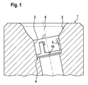
- a section of a fuel injection valve 1 is shown in longitudinal section.
- the fuel injection valve 1 is in particular an injection valve, as provided in gasoline or diesel injection systems in motor vehicles.
- the fuel injection valve 1 has an obliquely formed to the longitudinal axis 6 bore 2.
- the bore 2 has a conical insertion region 3 and a step 4.
- a fuel filter 10 according to the invention can be pressed into the cylindrical bore section 5 formed between the insertion region 3 and the step 4.
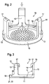
- the filter body of the fuel filter 10 has an approximately disc-shaped or cup-shaped bottom portion 11.
- a plurality of through holes 12 are formed in the radially inner region of the bottom portion 11.
- the through holes 12 extend at least substantially in the direction of the longitudinal axis 6 of the bore 2 in the fuel injection valve 1 and perpendicular to the bottom portion 11.
- the through holes 12 are preferably made by laser radiation and have a diameter of 40 .mu.m to 60 .mu.m, preferably of about 50 microns on.
- the bottom portion 11 protrude at the radially outer region on the upper side in the longitudinal direction extending three, each offset by 120 degrees to each other arranged holding webs 13 from.
- the cross-sectionally substantially rectangular support webs 13 are in this case, as in particular from Fig. 3 can be seen, by an angle ⁇ , which is greater than 90 degrees, in particular 93 degrees, elastically resiliently arranged to the bottom portion 11. Due to this arrangement, the fuel filter 10 on the bottom portion 11 opposite side of the holding webs 13 its largest outer diameter, which is greater than the diameter of the bore 2 in the fuel injection valve 1 in the radially unloaded state of the holding webs.
- the bottom portion 11 of the fuel filter 10 opposite end portion 15 of the holding webs 13 is bent radially inwardly, so that on the bottom portion 11 facing sides of the end portion 15 each results in a support shoulder 16.
- the upper side of the end regions 15 is in each case provided with a planar bearing surface 17, which are arranged parallel to the bottom region 11 of the fuel filter 10 when the fuel filter 10 is pressed into the bore 2 of the fuel injection valve 1.
- the fuel filter 10 described so far consists in particular of metal, and is produced by a punch bending process with the mentioned laser processing process for the formation of the through holes 12.
- the bottom region 11 in the transition region to a radial circumferential wall 18 inside a concave radius 20 has.
- the bottom portion 11 on its outer side an insertion bevel 21, which is formed in particular by a radius 22.
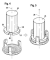
- the cylindrically formed Abziehstempel 25 has in its lower portion three, each 120 degrees to each other arranged grooves 26 on a radially encircling collar 27.
- the grooves 26 each have a width which corresponds at least to the width of the holding webs 13.
- the grooves 26 are aligned with the retaining webs 13 and guided to below the retaining shoulders 16, as shown in the Fig. 5 is shown.
- the Abziehstempel 25 is rotated in its longitudinal axis 28, so that the collar 27 of the Abziehstkovs 25 comes into coincidence with the retaining shoulders 16 of the retaining webs 13. Subsequently, the fuel filter 10 can be pulled out in the direction of the longitudinal axis 28 from the bore 2 of the fuel injection valve 1.
- the fuel filter 10 according to the invention can be modified or modified in many ways. So it is conceivable, for example, that the bottom portion 11 may also be formed cone or hemispherical. Furthermore, it is also conceivable that the fuel filter 10 is made of plastic.
Landscapes
- Engineering & Computer Science (AREA)
- Chemical & Material Sciences (AREA)
- Combustion & Propulsion (AREA)
- Mechanical Engineering (AREA)
- General Engineering & Computer Science (AREA)
- Manufacturing & Machinery (AREA)
- Fuel-Injection Apparatus (AREA)
Applications Claiming Priority (1)
| Application Number | Priority Date | Filing Date | Title |
|---|---|---|---|
| DE200910045347 DE102009045347A1 (de) | 2009-10-06 | 2009-10-06 | Kraftstofffilter für ein Kraftstoffeinspritzventil |
Publications (1)
| Publication Number | Publication Date |
|---|---|
| EP2309116A1 true EP2309116A1 (fr) | 2011-04-13 |
Family
ID=43413462
Family Applications (1)
| Application Number | Title | Priority Date | Filing Date |
|---|---|---|---|
| EP10177848A Withdrawn EP2309116A1 (fr) | 2009-10-06 | 2010-09-21 | Filtre à carburant pour une soupape d'injection de carburant |
Country Status (2)
| Country | Link |
|---|---|
| EP (1) | EP2309116A1 (fr) |
| DE (1) | DE102009045347A1 (fr) |
Families Citing this family (1)
| Publication number | Priority date | Publication date | Assignee | Title |
|---|---|---|---|---|
| CN114776501B (zh) * | 2022-04-21 | 2022-12-02 | 浙江双良汽车零部件有限公司 | 一种下置滤网组件快速更换的燃油泵总成 |
Citations (3)
| Publication number | Priority date | Publication date | Assignee | Title |
|---|---|---|---|---|
| JP2004308594A (ja) * | 2003-04-09 | 2004-11-04 | Denso Corp | 燃料噴射弁 |
| EP1806497A1 (fr) * | 2006-01-10 | 2007-07-11 | Siemens Aktiengesellschaft | Injecteur |
| EP2000662A1 (fr) * | 2007-06-04 | 2008-12-10 | Continental Automotive GmbH | Réglage et agencement de filtre pour soupape d'injection, et soupape d'injection |
Family Cites Families (2)
| Publication number | Priority date | Publication date | Assignee | Title |
|---|---|---|---|---|
| DE19832940A1 (de) | 1998-07-22 | 2000-01-27 | Bosch Gmbh Robert | Kraftstoffeinspritzventil für Brennkraftmaschinen |
| DE10307529A1 (de) | 2003-02-21 | 2004-09-02 | Robert Bosch Gmbh | Stabfilter für Kraftstoffeinspritzanlagen |
-
2009
- 2009-10-06 DE DE200910045347 patent/DE102009045347A1/de not_active Withdrawn
-
2010
- 2010-09-21 EP EP10177848A patent/EP2309116A1/fr not_active Withdrawn
Patent Citations (3)
| Publication number | Priority date | Publication date | Assignee | Title |
|---|---|---|---|---|
| JP2004308594A (ja) * | 2003-04-09 | 2004-11-04 | Denso Corp | 燃料噴射弁 |
| EP1806497A1 (fr) * | 2006-01-10 | 2007-07-11 | Siemens Aktiengesellschaft | Injecteur |
| EP2000662A1 (fr) * | 2007-06-04 | 2008-12-10 | Continental Automotive GmbH | Réglage et agencement de filtre pour soupape d'injection, et soupape d'injection |
Also Published As
| Publication number | Publication date |
|---|---|
| DE102009045347A1 (de) | 2011-04-07 |
Similar Documents
| Publication | Publication Date | Title |
|---|---|---|
| EP3580487B1 (fr) | Module connecteur destiné à être utilisé dans un véhicule | |
| EP3475589B1 (fr) | Système d'articulation, module préfabriqué et procédé de fabrication d'un module préfabriqué d'un système d'articulation | |
| EP0749378A1 (fr) | Raclette d'essuie-glace | |
| DE102011053786A1 (de) | Haltemittel mit einem axialen Durchgang zur Aufnahme eines Formatteiles | |
| DE102014208003A1 (de) | Planetenträger für ein Planetengetriebe aus verschweißten Teilen | |
| EP3157769B1 (fr) | Procédé servant à fabriquer un composant de châssis | |
| DE20221801U1 (de) | Mutter | |
| DE102007017138A1 (de) | Anordnung eines Planetenbolzens in einem Planetenträger und Verfahren zur Montage eines Planetenbolzens | |
| DE102004042478B4 (de) | Verfahren zur verdrehsicheren Befestigung eines Funktionselements in einem Bauteil sowie Verbindung zwischen einem Bauteil und einem Funktionselement | |
| EP2449659B1 (fr) | Procédé de fabrication d'un moteur électrique | |
| DE102011075837A1 (de) | Lagereinrichtung | |
| EP3054182B1 (fr) | Procédé de fabrication d'une liaison bout à bout entre un boîtier articulé et un composant de liaison et élément de construction fabriqué selon ledit procédé | |
| DE102006022382A1 (de) | Vorrichtung und Verfahren zur Befestigung eines Wischermotors an ein Wischergestänge | |
| DE102009045347A1 (de) | Kraftstofffilter für ein Kraftstoffeinspritzventil | |
| DE102018124493B4 (de) | Gelenkgehäuse und Verfahren zur Herstellung eines Gelenkgehäuses | |
| EP3599388B1 (fr) | Dispositif de chargement | |
| DE202008016230U1 (de) | Vorrichtung zum Verbinden von Bauteilen | |
| EP1910139A1 (fr) | Dispositif d'essuie-glace, en particulier pour vehicule automobile | |
| EP4012850B1 (fr) | Connecteur enfichable d'appareil à presser destiné à être assemblé par pression avec un boîtier métallique | |
| EP3988803B1 (fr) | Unité fonctionnelle pourvue d'élément de connexion et d'élément de fixation | |
| DE102019205257A1 (de) | Robuster Steckverbinder für medienführende Leitungen, Steckverbindungsanordnung und Kraftstoffinjektor | |
| DE202008006653U1 (de) | Steckbare Rohrverbindung | |
| DE202010005349U1 (de) | Doppelstanzbuchse sowie System aus einem Rohr und einer Doppelstanzbuchse | |
| DE202024001737U1 (de) | Beilagscheibensegment und Beilagscheibe | |
| DE102015225569A1 (de) | Werkzeug zum Schneiden eines Bauteils |
Legal Events
| Date | Code | Title | Description |
|---|---|---|---|
| PUAI | Public reference made under article 153(3) epc to a published international application that has entered the european phase |
Free format text: ORIGINAL CODE: 0009012 |
|
| AK | Designated contracting states |
Kind code of ref document: A1 Designated state(s): AL AT BE BG CH CY CZ DE DK EE ES FI FR GB GR HR HU IE IS IT LI LT LU LV MC MK MT NL NO PL PT RO SE SI SK SM TR |
|
| AX | Request for extension of the european patent |
Extension state: BA ME RS |
|
| 17P | Request for examination filed |
Effective date: 20111013 |
|
| STAA | Information on the status of an ep patent application or granted ep patent |
Free format text: STATUS: THE APPLICATION IS DEEMED TO BE WITHDRAWN |
|
| 18D | Application deemed to be withdrawn |
Effective date: 20150331 |