EP2309216A2 - Dispositif et procédé destinés à refroidir des produits - Google Patents
Dispositif et procédé destinés à refroidir des produits Download PDFInfo
- Publication number
- EP2309216A2 EP2309216A2 EP20100170553 EP10170553A EP2309216A2 EP 2309216 A2 EP2309216 A2 EP 2309216A2 EP 20100170553 EP20100170553 EP 20100170553 EP 10170553 A EP10170553 A EP 10170553A EP 2309216 A2 EP2309216 A2 EP 2309216A2
- Authority
- EP
- European Patent Office
- Prior art keywords
- nozzle
- nozzles
- treatment
- flow
- nozzle plate
- Prior art date
- Legal status (The legal status is an assumption and is not a legal conclusion. Google has not performed a legal analysis and makes no representation as to the accuracy of the status listed.)
- Withdrawn
Links
- 238000001816 cooling Methods 0.000 title claims abstract description 36
- 238000000034 method Methods 0.000 title claims abstract description 10
- 238000011144 upstream manufacturing Methods 0.000 claims abstract description 8
- 230000003287 optical effect Effects 0.000 claims description 5
- 239000012530 fluid Substances 0.000 claims 2
- 230000001105 regulatory effect Effects 0.000 claims 1
- 239000003570 air Substances 0.000 description 34
- 230000006978 adaptation Effects 0.000 description 2
- 238000005265 energy consumption Methods 0.000 description 2
- 238000004378 air conditioning Methods 0.000 description 1
- 239000012080 ambient air Substances 0.000 description 1
- 238000013459 approach Methods 0.000 description 1
- 238000005516 engineering process Methods 0.000 description 1
- 235000013305 food Nutrition 0.000 description 1
- 238000000265 homogenisation Methods 0.000 description 1
- 238000004519 manufacturing process Methods 0.000 description 1
- 239000000463 material Substances 0.000 description 1
- 238000005259 measurement Methods 0.000 description 1
- 239000002184 metal Substances 0.000 description 1
- 239000008267 milk Substances 0.000 description 1
- 210000004080 milk Anatomy 0.000 description 1
- 235000013336 milk Nutrition 0.000 description 1
- 239000005022 packaging material Substances 0.000 description 1
- 230000002093 peripheral effect Effects 0.000 description 1
- 238000007789 sealing Methods 0.000 description 1
Images


Classifications
-
- F—MECHANICAL ENGINEERING; LIGHTING; HEATING; WEAPONS; BLASTING
- F25—REFRIGERATION OR COOLING; COMBINED HEATING AND REFRIGERATION SYSTEMS; HEAT PUMP SYSTEMS; MANUFACTURE OR STORAGE OF ICE; LIQUEFACTION SOLIDIFICATION OF GASES
- F25D—REFRIGERATORS; COLD ROOMS; ICE-BOXES; COOLING OR FREEZING APPARATUS NOT OTHERWISE PROVIDED FOR
- F25D17/00—Arrangements for circulating cooling fluids; Arrangements for circulating gas, e.g. air, within refrigerated spaces
- F25D17/005—Arrangements for circulating cooling fluids; Arrangements for circulating gas, e.g. air, within refrigerated spaces in cold rooms
-
- F—MECHANICAL ENGINEERING; LIGHTING; HEATING; WEAPONS; BLASTING
- F25—REFRIGERATION OR COOLING; COMBINED HEATING AND REFRIGERATION SYSTEMS; HEAT PUMP SYSTEMS; MANUFACTURE OR STORAGE OF ICE; LIQUEFACTION SOLIDIFICATION OF GASES
- F25D—REFRIGERATORS; COLD ROOMS; ICE-BOXES; COOLING OR FREEZING APPARATUS NOT OTHERWISE PROVIDED FOR
- F25D17/00—Arrangements for circulating cooling fluids; Arrangements for circulating gas, e.g. air, within refrigerated spaces
- F25D17/04—Arrangements for circulating cooling fluids; Arrangements for circulating gas, e.g. air, within refrigerated spaces for circulating air, e.g. by convection
- F25D17/042—Air treating means within refrigerated spaces
- F25D17/045—Air flow control arrangements
-
- F—MECHANICAL ENGINEERING; LIGHTING; HEATING; WEAPONS; BLASTING
- F25—REFRIGERATION OR COOLING; COMBINED HEATING AND REFRIGERATION SYSTEMS; HEAT PUMP SYSTEMS; MANUFACTURE OR STORAGE OF ICE; LIQUEFACTION SOLIDIFICATION OF GASES
- F25B—REFRIGERATION MACHINES, PLANTS OR SYSTEMS; COMBINED HEATING AND REFRIGERATION SYSTEMS; HEAT PUMP SYSTEMS
- F25B2600/00—Control issues
- F25B2600/11—Fan speed control
- F25B2600/112—Fan speed control of evaporator fans
Definitions
- the invention relates to a treatment device and a method for cooling products with a gaseous treatment medium, preferably air, with a blower arrangement for generating a flow of the treatment medium, at least one cooling device, at least one nozzle plate having a plurality of openings in the form of nozzles or nozzle groups , For generating individual working flows of the treatment medium and at least one of the nozzle plate upstream treatment station, for the product stack to be treated, which can be acted upon by the nozzle or nozzle groups of the nozzle plate with the treatment medium.
- a gaseous treatment medium preferably air
- Such treatment devices are used, for example, food products, eg. B. Milk products to cool after the manufacturing process. While the products pass through the treatment device, they are treated with defined climatic conditions, for example by flowing around with cool air to cool them to a predetermined, suitable for subsequent storage temperature.
- the products to be treated are stacked on pallets to product stack and retracted into the treatment device, so that a large number of such products can be treated simultaneously.
- Such a treatment device or cooling tunnel is from the DE 100 17 408 A1 known.
- the product stack is transported past for cooling on vertically arranged nozzle plates, which blow cold air horizontally through the product layers.
- the cooling capacity, the cooling tunnel length and the transport speed through the tunnel are designed so that the desired cooling of the products is achieved.
- the discontinuous mode of operation as in the EP 1 455 151 A1 disclosed.
- the products to be cooled are deposited at a treatment position and blown there with cold air until the desired cooling is achieved. Subsequently, the product stacks are moved out of the cooling tunnel.
- the nozzle plate consists of a plurality of separate inlet nozzles through which a plurality of defined inflow points is formed over the inflow region, into which the gaseous treatment medium flows on the one hand with a defined direction and on the other with a defined speed.
- the inflow velocity which has the gaseous treatment medium in the outlet region of the inlet nozzles, is preferably in the range of 20-25 m / s.
- Such a high inflow velocity ensures that, also due to the relatively concentrated beams of incoming gaseous treatment medium, even the smallest gaps between the individual products to be treated or smallest openings in packaging materials containing these products, for example cardboard, are flowed through.
- the treatment medium thus also approaches these products in the inner volume range of the products stacked on the pallets and can contribute to their treatment, for example their cooling.
- a disadvantage of this type of cooling tunnels and nozzle plate is that no adaptation to the pallet loading takes place and so the energy requirements for the pressure supply device for generating the required flow rate at not fully loaded pallets is almost as high as in fully loaded pallets.
- the invention is therefore based on the object to provide a treatment device with a higher energy efficiency, which allows adaptation to the pallet load.
- a treatment device for cooling products with a gaseous treatment medium is proposed.
- the treatment medium is preferably ambient air, which generates a circular base flow in the treatment device by means of a blower arrangement for generating a flow of the treatment medium.
- the circular base flow in this case flows through at least one cooling device, at least one nozzle plate having a plurality of openings in the form of nozzles or nozzle groups, for generating individual working flows of the treatment medium and at least one treatment station upstream of the nozzle plate, for the product stacks to be treated through the nozzles or Nozzle groups of the nozzle plate can be acted upon with the treatment medium.
- a pressure control is also available for pressure control of the specialistssmediumstau Kunststoffs before the nozzle openings.
- the pressure control is effected in an advantageous manner that a constant working flow in the outlet region of the nozzle or nozzle groups is generated and can be adapted to the flow resistance through the nozzle plate and the product stack. If a lower dynamic pressure is required, the speed of the fans and thus the energy consumption can be reduced.
- the nozzles For cooling the product stacks, it is essentially necessary for the nozzles to be active, generating a working flow that hits the product stack. All nozzles whose working flows pass the product stack have no or negligible influence on the cooling of the products and are sealed according to the invention.
- nozzles or nozzle groups For closing individual nozzles or nozzle groups on the nozzle plate means are present, such as sliding closure plates.
- the nozzles or nozzle groups are closable in such a way that only the nozzles or nozzle groups are open, meet the working currents on the product stack.
- the closure of the nozzles takes place according to the invention on the basis of the determined stack height. The more nozzles are closed, the lower the fan speed can be selected to generate the required back pressure and thus also reduces the energy consumption of the fans.
- nozzle openings in the nozzle plate which generate a turbulent flow and / or a laminar flow.
- the nozzle plate is designed so that a working flow of the treatment medium is formed in which turbulent flows are supported by laminar flows.
- a further embodiment of the nozzle plate which has different nozzle openings, through which the working flow is divided into a primary air flow and a secondary air flow.
- the division takes place so that a working flow of the treatment medium with a primary air flow (19) and a secondary air flow (20) is formed, these having different flow velocities.
- the different nozzle openings for generating the different air flows are arranged so that the secondary air flow substantially completely surrounds the primary air flow and the Primary air flow has a mean higher flow rate than the secondary air flow.
- the different flows could e.g. can be achieved by different nozzle sizes and / or nozzle shapes.
- the primary flow should be interpreted as a turbulent flow and the secondary flow as a laminar flow.
- the working flow leaves the nozzles, the nozzle groups or the primary nozzle orifice of the nozzle plate at a flow rate in the range of 15-30 m / s, preferably 20-25 m / s.
- the secondary flow leaves the nozzles at a flow rate in the range of 0.1-5m / s.
- nozzles or nozzle groups adjustable on the nozzle plate, so that the working flows of the individual nozzles of the nozzle plate can be steered onto the product stack.
- the entire working flow flows through the product stack and individual working flows can be directed to critical points of the product stack.
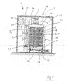
- FIG. 1 illustrates in simplified representation the structure of an inventively designed cooling tunnel in section.
- the product stack 11 is shown stacked on the pallet 30.
- the cooling tunnel consists of a plurality of successively arranged treatment stations 10 through which the loaded pallet can be transported on the transport device 16.
- the treatment stations 10 are bounded or closed at the top by a wall 34 formed of sheet material, for example, and have an inflow region 36 for gaseous treatment medium on one side and an outflow region 38 for the gaseous treatment medium on the other side.
- a wall 34 formed of sheet material, for example, and have an inflow region 36 for gaseous treatment medium on one side and an outflow region 38 for the gaseous treatment medium on the other side.
- an air cooler 6 may be provided when the gaseous treatment medium for cooling the products 2 cooling air is used.
- a plurality of nozzle plates 6 are provided with nozzles 7, through which, as indicated by arrows P1, the cooling air can flow laterally into the treatment chamber 28, there is a working flow 9, which may consist of individual turbulent and / or laminar flows ,
- a pressure measuring device 15 is provided at least one point in front of the nozzle plate 6
- the cooling air or the working flow 9 After the cooling air or the working flow 9 has flowed through the products to be treated, or has flowed along the products to be treated, it exits, as indicated by arrows P2, from the stack of products to be treated 2 and enters the outlet region 38 in the air cooler 40 or any other treatment arrangement for a gaseous treatment medium. Subsequent to the outflow region 38 or the air cooler 5, a flow channel region 44 is provided, in which the cooling air flows to a blower arrangement 4, which in turn is followed by a flow channel region 48, via which the cooling air conveyed through the blower arrangement 4 can then flow to the inflow region 36. The result is a circular circulation of the cooling air or the treatment medium.
- flow channel regions 44, 48 may be delimited, for example, by a wall arrangement 50 surrounding the entire tunable section 18.
- flow channels known per se in the area of air conditioning technology for example formed from sheet metal parts.
- a weight sensor 12 To determine the stack height is below the pallet 30, a weight sensor 12, by means of which the stack height can be determined.
- the nozzles 7 or nozzle groups 8 in the nozzle plate can be opened or closed as exemplified in FIG FIG. 2 shown.
- a movably arranged closure plate 14 is arranged in front of the nozzle group 8. With this exemplified closure plate, the upper nozzle group 8 can be closed.
- FIGS. 3 and 4 further embodiment of the nozzle plates 6 are shown. So is in FIG. 3 a nozzle plate shown with different nozzle openings.
- a primary air flow and a secondary air flow can be generated, which have different flow velocities.
- the primary air flow with a comparatively high flow rate embedded or trapped in a secondary air stream at a lower flow rate.
- the secondary air flow thus surrounds the primary air flow at a peripheral surface or outer surface enclosing the flow lines or flow direction of the primary air flow.
- the primary air flow 19 with the high flow velocity also carries with it the secondary air flow 20 and aligns it with according to the flow guidance of the primary air flow 19 with.
- a working flow 9 is generated, which improves the loading of the product stack, whereby a more uniform cooling of the products can be achieved.
- nozzle openings and / or shapes are achieved by means of different sized nozzle openings and / or shapes.
- a variant of a nozzle plate is shown, which consists of a cavity 21 having a nozzle plate with a front and a back.
- the primary air flow 19 is generated in that the treatment medium 3 is directed from the back by relatively large nozzles which pass through the cavity of the nozzle plate 6 to the front.
- the secondary flow 20, is generated by the treatment medium flowing into the cavity 21 of the nozzle plate and exiting from there through relatively small nozzles on the front side.
- FIG. 4 a nozzle plate is shown with adjustable nozzles, so that the flow guide can be selected individually depending on the product stacks and the packages.
Landscapes
- Engineering & Computer Science (AREA)
- Chemical & Material Sciences (AREA)
- Combustion & Propulsion (AREA)
- Physics & Mathematics (AREA)
- Mechanical Engineering (AREA)
- Thermal Sciences (AREA)
- General Engineering & Computer Science (AREA)
Applications Claiming Priority (1)
| Application Number | Priority Date | Filing Date | Title |
|---|---|---|---|
| DE200910045211 DE102009045211A1 (de) | 2009-09-30 | 2009-09-30 | Vorrichtung und Verfahren zum Kühlen von Erzeugnissen |
Publications (1)
| Publication Number | Publication Date |
|---|---|
| EP2309216A2 true EP2309216A2 (fr) | 2011-04-13 |
Family
ID=43305052
Family Applications (1)
| Application Number | Title | Priority Date | Filing Date |
|---|---|---|---|
| EP20100170553 Withdrawn EP2309216A2 (fr) | 2009-09-30 | 2010-07-23 | Dispositif et procédé destinés à refroidir des produits |
Country Status (2)
| Country | Link |
|---|---|
| EP (1) | EP2309216A2 (fr) |
| DE (1) | DE102009045211A1 (fr) |
Citations (2)
| Publication number | Priority date | Publication date | Assignee | Title |
|---|---|---|---|---|
| DE10017408A1 (de) | 2000-04-07 | 2001-10-11 | Wiessner Gmbh | Behandlungs-Tunelleinrichtung, insbesondere Kühltunell |
| EP1455151A1 (fr) | 2003-03-07 | 2004-09-08 | M+W Zander Facility Engineering GmbH | Procédé pour refroidir des produits, notamment d'aliments, en particulier des produits laitiers, et dispositif pour sa mise en oeuvre |
-
2009
- 2009-09-30 DE DE200910045211 patent/DE102009045211A1/de not_active Withdrawn
-
2010
- 2010-07-23 EP EP20100170553 patent/EP2309216A2/fr not_active Withdrawn
Patent Citations (2)
| Publication number | Priority date | Publication date | Assignee | Title |
|---|---|---|---|---|
| DE10017408A1 (de) | 2000-04-07 | 2001-10-11 | Wiessner Gmbh | Behandlungs-Tunelleinrichtung, insbesondere Kühltunell |
| EP1455151A1 (fr) | 2003-03-07 | 2004-09-08 | M+W Zander Facility Engineering GmbH | Procédé pour refroidir des produits, notamment d'aliments, en particulier des produits laitiers, et dispositif pour sa mise en oeuvre |
Also Published As
| Publication number | Publication date |
|---|---|
| DE102009045211A1 (de) | 2011-03-31 |
Similar Documents
| Publication | Publication Date | Title |
|---|---|---|
| EP2049401B1 (fr) | Procédé pour emmancher un film rétractable sur des emballages et dispositif pour réaliser le procédé | |
| EP2554483B1 (fr) | Tunnel de rétraction | |
| EP3504363B1 (fr) | Four d'oxydation | |
| EP3672893B1 (fr) | Dispositif d'écartement pourvu de dispositif de stabilisation à l'effet coand | |
| DE102012103398B4 (de) | Schrumpfvorrichtung mit Blendenleiste | |
| DE102007059654A1 (de) | Behandlungsvorrichtung zum Kühlen und/oder Erwärmen von Gegenständen | |
| DE102013000754A1 (de) | Vorrichtung zum Temperieren von Gegenständen | |
| DE102021103837A1 (de) | Schrumpfvorrichtung und Verfahren zum Optimieren des Energieaustrags einer Schrumpfvorrichtung | |
| WO1997005437A1 (fr) | Procede et dispositif de sechage de briques crues ceramique | |
| EP2551207A1 (fr) | Dispositif de rétractation avec refroidissement de gerbe | |
| EP4043354A1 (fr) | Dispositif de rétraction, procédé d'optimisation de la rétraction d'une matière d'emballage au niveau d'un assemblage comprenant au moins un article et un module de retrait | |
| DE102011011279A1 (de) | Apparatur zur Leitung des Gasstromes beim Belüften innerhalb eines Vakuumgehäuses | |
| EP2586717B1 (fr) | Tunnel de rétraction | |
| EP2309216A2 (fr) | Dispositif et procédé destinés à refroidir des produits | |
| DE3710901C2 (fr) | ||
| EP3059528B1 (fr) | Enceinte de stockage frigorifique et procede d'operation d'une telle enceinte | |
| EP2771630B1 (fr) | Dispositif de refroidissement | |
| DE4116019C2 (de) | Verfahren und Vorrichtung zum Kühlen eines flächenhaften Gutes, insbesondere eines Metallbandes | |
| DE102013101477A1 (de) | Schrumpfvorrichtung | |
| DE69407857T2 (de) | Kühleinheit für pastenförmige Produkte in Strangform | |
| EP0174589A1 (fr) | Dispositif pour le chauffage ou le refroidissement de produits métalliques | |
| DE102011080807A1 (de) | Düsenwandelement für einen Kühltunnel | |
| DE1900287A1 (de) | Vorrichtung zur thermischen Behandlung von Bandmaterial | |
| DE2103674C3 (de) | Verfahren und Vorrichtung zum Kühlen von heißen Schüttgütern in offenen Kühlern | |
| DE102009045152A1 (de) | Verfahren und Kühltunnel zum Kühlen von Gütern |
Legal Events
| Date | Code | Title | Description |
|---|---|---|---|
| PUAI | Public reference made under article 153(3) epc to a published international application that has entered the european phase |
Free format text: ORIGINAL CODE: 0009012 |
|
| AK | Designated contracting states |
Kind code of ref document: A2 Designated state(s): AL AT BE BG CH CY CZ DE DK EE ES FI FR GB GR HR HU IE IS IT LI LT LU LV MC MK MT NL NO PL PT RO SE SI SK SM TR |
|
| AX | Request for extension of the european patent |
Extension state: BA ME RS |
|
| STAA | Information on the status of an ep patent application or granted ep patent |
Free format text: STATUS: THE APPLICATION IS DEEMED TO BE WITHDRAWN |
|
| 18D | Application deemed to be withdrawn |
Effective date: 20130201 |