EP2309587A2 - Anordnung eines Klammermechanismus und LNB und Parabolantenne mit einer solchen Anordnung - Google Patents
Anordnung eines Klammermechanismus und LNB und Parabolantenne mit einer solchen Anordnung Download PDFInfo
- Publication number
- EP2309587A2 EP2309587A2 EP10176894A EP10176894A EP2309587A2 EP 2309587 A2 EP2309587 A2 EP 2309587A2 EP 10176894 A EP10176894 A EP 10176894A EP 10176894 A EP10176894 A EP 10176894A EP 2309587 A2 EP2309587 A2 EP 2309587A2
- Authority
- EP
- European Patent Office
- Prior art keywords
- lnb
- clamping part
- assembly
- clamping mechanism
- clamping
- Prior art date
- Legal status (The legal status is an assumption and is not a legal conclusion. Google has not performed a legal analysis and makes no representation as to the accuracy of the status listed.)
- Withdrawn
Links
- 238000005192 partition Methods 0.000 claims description 3
- 238000010586 diagram Methods 0.000 description 9
- 230000001419 dependent effect Effects 0.000 description 1
- 230000005236 sound signal Effects 0.000 description 1
Images


Classifications
-
- H—ELECTRICITY
- H01—ELECTRIC ELEMENTS
- H01Q—ANTENNAS, i.e. RADIO AERIALS
- H01Q1/00—Details of, or arrangements associated with, antennas
- H01Q1/12—Supports; Mounting means
- H01Q1/125—Means for positioning
- H01Q1/1257—Means for positioning using the received signal strength
-
- H—ELECTRICITY
- H01—ELECTRIC ELEMENTS
- H01Q—ANTENNAS, i.e. RADIO AERIALS
- H01Q1/00—Details of, or arrangements associated with, antennas
- H01Q1/12—Supports; Mounting means
- H01Q1/1207—Supports; Mounting means for fastening a rigid aerial element
-
- H—ELECTRICITY
- H01—ELECTRIC ELEMENTS
- H01Q—ANTENNAS, i.e. RADIO AERIALS
- H01Q1/00—Details of, or arrangements associated with, antennas
- H01Q1/12—Supports; Mounting means
- H01Q1/1242—Rigid masts specially adapted for supporting an aerial
-
- H—ELECTRICITY
- H01—ELECTRIC ELEMENTS
- H01Q—ANTENNAS, i.e. RADIO AERIALS
- H01Q1/00—Details of, or arrangements associated with, antennas
- H01Q1/12—Supports; Mounting means
- H01Q1/125—Means for positioning
- H01Q1/1264—Adjusting different parts or elements of an aerial unit
-
- H—ELECTRICITY
- H01—ELECTRIC ELEMENTS
- H01Q—ANTENNAS, i.e. RADIO AERIALS
- H01Q1/00—Details of, or arrangements associated with, antennas
- H01Q1/12—Supports; Mounting means
- H01Q1/22—Supports; Mounting means by structural association with other equipment or articles
- H01Q1/24—Supports; Mounting means by structural association with other equipment or articles with receiving set
- H01Q1/247—Supports; Mounting means by structural association with other equipment or articles with receiving set with frequency mixer, e.g. for direct satellite reception or Doppler radar
-
- H—ELECTRICITY
- H01—ELECTRIC ELEMENTS
- H01Q—ANTENNAS, i.e. RADIO AERIALS
- H01Q19/00—Combinations of primary active antenna elements and units with secondary devices, e.g. with quasi-optical devices, for giving the antenna a desired directional characteristic
- H01Q19/02—Details
-
- H—ELECTRICITY
- H01—ELECTRIC ELEMENTS
- H01Q—ANTENNAS, i.e. RADIO AERIALS
- H01Q19/00—Combinations of primary active antenna elements and units with secondary devices, e.g. with quasi-optical devices, for giving the antenna a desired directional characteristic
- H01Q19/02—Details
- H01Q19/021—Means for reducing undesirable effects
- H01Q19/028—Means for reducing undesirable effects for reducing the cross polarisation
-
- H—ELECTRICITY
- H01—ELECTRIC ELEMENTS
- H01Q—ANTENNAS, i.e. RADIO AERIALS
- H01Q19/00—Combinations of primary active antenna elements and units with secondary devices, e.g. with quasi-optical devices, for giving the antenna a desired directional characteristic
- H01Q19/10—Combinations of primary active antenna elements and units with secondary devices, e.g. with quasi-optical devices, for giving the antenna a desired directional characteristic using reflecting surfaces
- H01Q19/12—Combinations of primary active antenna elements and units with secondary devices, e.g. with quasi-optical devices, for giving the antenna a desired directional characteristic using reflecting surfaces wherein the surfaces are concave
-
- H—ELECTRICITY
- H01—ELECTRIC ELEMENTS
- H01Q—ANTENNAS, i.e. RADIO AERIALS
- H01Q19/00—Combinations of primary active antenna elements and units with secondary devices, e.g. with quasi-optical devices, for giving the antenna a desired directional characteristic
- H01Q19/10—Combinations of primary active antenna elements and units with secondary devices, e.g. with quasi-optical devices, for giving the antenna a desired directional characteristic using reflecting surfaces
- H01Q19/12—Combinations of primary active antenna elements and units with secondary devices, e.g. with quasi-optical devices, for giving the antenna a desired directional characteristic using reflecting surfaces wherein the surfaces are concave
- H01Q19/13—Combinations of primary active antenna elements and units with secondary devices, e.g. with quasi-optical devices, for giving the antenna a desired directional characteristic using reflecting surfaces wherein the surfaces are concave the primary radiating source being a single radiating element, e.g. a dipole, a slot, a waveguide termination
- H01Q19/132—Horn reflector antennas; Off-set feeding
Definitions
- the present invention is related to an assembly of a clamping mechanism and an LNB and a dish antenna using the same, and more specifically, to a fastening apparatus for the tuning of the dish antenna angle.
- a satellite television system employs a dish antenna to collect satellite signals, and the signals are then reflected to low noise block down converters (LNB) positioned at the focus of the dish antenna for amplifying the signals and reducing their frequencies down to around 1GHz, i.e., to an intermediate frequency.
- LNB low noise block down converters
- the adjusted signals are transmitted via a cable to an indoor television channel selector for selecting the signals of a desired channel, and the selected signals are then amplified, modulated and converted into video and audio signals for television viewing.
- a dish antenna is a highly directional receiving device, which has to be precisely directed toward satellites in orbit at 36,000 kilometers altitude. For example, if a dish antenna with a 180 cm diameter shifts 2 cm horizontally, or 3 cm vertically, the signals will become weak or even disappear. In addition, if a dish antenna uses the Ka band, i.e., 26 to 40 GHz, an adjustment accuracy of 0.1 degrees is needed, and the tolerance has to be within 0.02 degrees for aiming at satellites precisely.
- a dish antenna using the Ka band is adjusted by using a programmable logic controller (PLC) in control of servo motors; however, the high cost significantly limits its popularity.
- PLC programmable logic controller
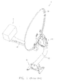
- FIG. 1 illustrates a known adjustable antenna apparatus 1 including a dish antenna 10, an LNB 11, a support rod 12, an adjustable dish bracket 13, a fixing arm 15, and an adjustable base member 14.
- the adjustable antenna apparatus 1 is disposed in different manners by securing the adjustable base member 14 at different places such as a vertical wall surface or a horizontal or inclined roof
- the adjustable dish bracket 13 is used for adjusting the orientation of the dish antenna 10 to obtain optimal signal-reception performance.
- the fixing arm 15 is tightened to securely hold the LNB 11, however, the LNB 11 cannot be easily adjusted to an optimal receiving position by tuning its angle. If receiving signals are still weak after the fixing arm 15 is fastened, the fixing arm 15 needs to be loosened for releasing the LNB 11.
- the optimal receiving position is not easy to be properly set because of repeated assembly and disassembly, so the position adjustment is time-consuming.
- the present invention provides an assembly of a clamping mechanism and an LNB and a dish antenna using the same. After the clamping mechanism and the LNB are combined, the angle of the LNB can be fine-tuned relative to the clamping mechanism while the clamping mechanism still holds the LNB. The fine angle adjustment is conducted while the LNB is fastened, and the clamping mechanism does not need to be unfastened. Consequently, the optimal receiving position is easily located, and the position is not by a screwing or fastening movement.
- an assembly of a clamping mechanism and an LNB comprises a clamping mechanism and an LNB (low noise block down converter).
- the clamping mechanism includes a first clamping part, a second clamping part, and a plurality of rectangular grooves.
- the LNB includes a shell, at least one flexible portion, and at least one rib portion.
- the first clamping part and the second clamping part clasp around the LNB, and are combined with each other by at least one fastening part.
- the at least one flexible portion is disposed on the shell of the LNB, and the rib portion is on the flexible portion.
- the plurality of rectangular grooves are closely arranged in parallel on the inner surface of the second clamping, and the rib portion is contained in one of the rectangular grooves.
- a dish antenna comprises a dish, an LNB, a clamping mechanism, an angle adjustment apparatus, and an adjustable stand.
- the dish is mounted on the angle adjustment apparatus, and the angle adjustment apparatus is connected to the adjustable stand.
- the clamping mechanism is fixed on the dish, and includes a first clamping part, a second clamping part, and a plurality of rectangular grooves.
- the LNB includes a shell, at least one flexible portion, and at least one rib portion. The first clamping part and the second clamping part clasp around the LNB, and are combined with each other by at least one fastening part.
- the at least one flexible portion is disposed on the shell of the LNB, and the rib portion is on the flexible portion.
- the plurality of rectangular grooves are closely arranged in parallel on the inner surface of the second clamping part, and the rib portion is contained in one of the rectangular grooves.
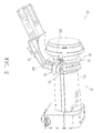
- FIG. 2 is a perspective diagram showing an assembly of a clamping mechanism and an LNB in accordance with an embodiment of the present invention.
- FIG. 3A is an exploded diagram showing an assembly of a clamping mechanism and an LNB in accordance with an embodiment of the present invention.
- the assembly 20 comprises a clamping mechanism 28 and an LNB 21.
- the clamping mechanism 28 includes a first clamping part 22, a second clamping part 23, and at least one ratchet 221.
- the LNB 21 includes a shell 211, at least one flexible portion 212 (referring to FIG. 3 ), and at least one rib portion 214 (referring to FIG. 3 ).
- the first clamping part 22 and the second clamping part 23 clasp around the LNB 21, and are combined with each other by at least one fastening part 24.
- the first clamping part 22 and the second clamping part 23 are able to pivot relative to each other through a first pivoting portion 222 and a second pivoting portion 234.
- the second clamping part 23 is connected to a connection ann 25.
- the connection arm 25 is connected to a fixing arm (referring to reference numeral 15 in FIG. 1 ) so as to be fixed to a dish (referring to reference numeral 10 in FIG. 1 ).
- the at least one flexible portion 212 is disposed on the shell 211 of the LNB 21, and the rib portion 214 is on the flexible portion 212.
- the rib portion 214 comprises a detent part 2141 and two guiding parts 2142 disposed on two ends of the detent part 2141.
- the rib portion 214 is not limited by the present embodiment, and has various changes its configuration.
- the two guiding parts 2142 make the rib portion 214 easy to move.
- the detent part 2141 by itself is enough for the embodiment and can function without the guiding parts 2142. As shown in FIG.
- the plurality of rectangular grooves 233 are closely arranged in parallel on the inner surface of the second clamping part 23, and the rib portion 214 is contained in one of the rectangular grooves 233.
- Each of the lateral guiding grooves 232 is on one side of the rectangular grooves 233 so the guiding parts 2142 on the two ends of the rib portion 214 can slide in the lateral guiding grooves 232.
- the plurality of the rectangular grooves 233 and the lateral guiding grooves 232 are named as a ratchet 231.
- another ratchet 221 is disposed on the second clamping part 23.
- Another rib portion (not shown) engaged in the ratchet 221 is opposite the rib portion 214 with a relative angle of 180° so the rotation motion for the position adjustment is more stable and the clamping force is also increased.
- the number of pairs of the rib portion and the ratchet is not limited by the present embodiment, and can be one or more.
- the rib portions and the ratchets can be disposed on the parting lines, but the rib portions and the ratchets of the present embodiment are not disposed on the parting lines.
- the flexible portion 212 is a cantilever defined by a C-shaped slit 213 on the shell 211.
- an external guiding groove 272 is provided on the shell 211.
- An external guiding rail 271 disposed on the first clamping part 22 can engage with the external guiding groove 272 so the external guiding rail 271 slides in the external guiding groove 272 and is constrained by the inner walls of the external guiding groove 272.
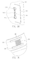
- FIG. 4A shows a flexible portion 212' in accordance with another embodiment of the present invention.
- the flexible portion 212' is a cantilever defined by a semicircular-shaped slit 213' on the shell 211'.
- the rib portion 214' is provided on the surface of the flexible portion 212'. Compared with FIG. 3 , there are no guiding parts on two ends of the rib portion 214'.
- FIG. 4B shows a ratchet in accordance with another embodiment of the present invention.
- the ratchet 231' only comprises a plurality of adjacent grooves 233'.
Landscapes
- Engineering & Computer Science (AREA)
- Radar, Positioning & Navigation (AREA)
- Remote Sensing (AREA)
- Support Of Aerials (AREA)
- Aerials With Secondary Devices (AREA)
Applications Claiming Priority (1)
| Application Number | Priority Date | Filing Date | Title |
|---|---|---|---|
| TW098132414A TW201112494A (en) | 2009-09-25 | 2009-09-25 | Assembly of clamping mechanism and LNB and disk antenna using the same |
Publications (2)
| Publication Number | Publication Date |
|---|---|
| EP2309587A2 true EP2309587A2 (de) | 2011-04-13 |
| EP2309587A3 EP2309587A3 (de) | 2012-03-28 |
Family
ID=43302646
Family Applications (1)
| Application Number | Title | Priority Date | Filing Date |
|---|---|---|---|
| EP10176894A Withdrawn EP2309587A3 (de) | 2009-09-25 | 2010-09-15 | Anordnung eines Klammermechanismus und LNB und Parabolantenne mit einer solchen Anordnung |
Country Status (3)
| Country | Link |
|---|---|
| US (1) | US20110074651A1 (de) |
| EP (1) | EP2309587A3 (de) |
| TW (1) | TW201112494A (de) |
Cited By (1)
| Publication number | Priority date | Publication date | Assignee | Title |
|---|---|---|---|---|
| EP3154129A4 (de) * | 2014-06-04 | 2017-12-20 | Abreu, João Do Espírito Santo | Parabolantenne mit selbststrukturiertem reflektor |
Family Cites Families (4)
| Publication number | Priority date | Publication date | Assignee | Title |
|---|---|---|---|---|
| WO2002035960A1 (en) * | 2000-11-02 | 2002-05-10 | Outrigger, Inc. | Extendable and angularly adjustable handle for wheeled luggage |
| JP4071687B2 (ja) * | 2003-08-11 | 2008-04-02 | シャープ株式会社 | 位置決め機構およびアンテナ装置 |
| JP2005269749A (ja) * | 2004-03-17 | 2005-09-29 | Nippon Tsushin Doboku Engineering Kk | 管路用止水栓の除去装置 |
| JP4294599B2 (ja) * | 2005-01-26 | 2009-07-15 | シャープ株式会社 | 電波受信用コンバータおよびアンテナ |
-
2009
- 2009-09-25 TW TW098132414A patent/TW201112494A/zh unknown
-
2010
- 2010-09-10 US US12/879,422 patent/US20110074651A1/en not_active Abandoned
- 2010-09-15 EP EP10176894A patent/EP2309587A3/de not_active Withdrawn
Non-Patent Citations (1)
| Title |
|---|
| None |
Cited By (1)
| Publication number | Priority date | Publication date | Assignee | Title |
|---|---|---|---|---|
| EP3154129A4 (de) * | 2014-06-04 | 2017-12-20 | Abreu, João Do Espírito Santo | Parabolantenne mit selbststrukturiertem reflektor |
Also Published As
| Publication number | Publication date |
|---|---|
| TW201112494A (en) | 2011-04-01 |
| EP2309587A3 (de) | 2012-03-28 |
| US20110074651A1 (en) | 2011-03-31 |
Similar Documents
| Publication | Publication Date | Title |
|---|---|---|
| US20100259462A1 (en) | Angle adjustment apparatus of dish antenna and dish antenna using the same | |
| US10784559B2 (en) | Rail-type portable satellite communication antenna | |
| US8736512B2 (en) | Item mounting system | |
| US8378919B2 (en) | Angle adjustment apparatus of dish antenna and dish antenna using the same | |
| US9857023B2 (en) | Mounting assembly for mounting an antenna | |
| KR100883361B1 (ko) | 이동체 탑재형 삼중대역 안테나 시스템 | |
| US20120081263A1 (en) | Position Adjustment Device and Satellite Antenna Thereof | |
| JP3181923B2 (ja) | 調整可能な設置および整列機構を有するマイクロ波トランシーバ、アンテナシステム | |
| US8350778B2 (en) | Adjustment method for dish antenna | |
| US11631929B2 (en) | Fastening device and associated method | |
| US6762731B1 (en) | Dish antenna rotation apparatus | |
| US8081133B2 (en) | Satellite antenna with holder assembly for holding LNBF | |
| EP2309587A2 (de) | Anordnung eines Klammermechanismus und LNB und Parabolantenne mit einer solchen Anordnung | |
| US20240266711A1 (en) | Antenna mount extension bracket with a retention and alignment clip | |
| US4565346A (en) | Adjustable bracket mount | |
| US10305180B2 (en) | Satellite reception assembly with phased horn array | |
| JPS6016124B2 (ja) | アンテナ角度調節装置 | |
| CN101872898B (zh) | 碟型天线的角度调整装置及碟型天线 | |
| US20160268673A1 (en) | Adjustable antenna and antenna mounting | |
| WO2004105177A3 (en) | Waveguide slot antenna | |
| KR20210043172A (ko) | 밀리미터 웨이브 통신을 제공하는 전자 장치 및 마운트 부재 | |
| EP3254336B1 (de) | Hochfrequenzanordnung | |
| US9401546B2 (en) | mmW low sidelobe constant beamwidth scanning antenna system | |
| CN101814655B (zh) | 碟型天线的调整方法 | |
| AU2019100223A4 (en) | Rail-type portable satellite communication antenna |
Legal Events
| Date | Code | Title | Description |
|---|---|---|---|
| PUAI | Public reference made under article 153(3) epc to a published international application that has entered the european phase |
Free format text: ORIGINAL CODE: 0009012 |
|
| AK | Designated contracting states |
Kind code of ref document: A2 Designated state(s): AL AT BE BG CH CY CZ DE DK EE ES FI FR GB GR HR HU IE IS IT LI LT LU LV MC MK MT NL NO PL PT RO SE SI SK SM TR |
|
| AX | Request for extension of the european patent |
Extension state: BA ME RS |
|
| PUAL | Search report despatched |
Free format text: ORIGINAL CODE: 0009013 |
|
| AK | Designated contracting states |
Kind code of ref document: A3 Designated state(s): AL AT BE BG CH CY CZ DE DK EE ES FI FR GB GR HR HU IE IS IT LI LT LU LV MC MK MT NL NO PL PT RO SE SI SK SM TR |
|
| AX | Request for extension of the european patent |
Extension state: BA ME RS |
|
| RIC1 | Information provided on ipc code assigned before grant |
Ipc: H01Q 19/13 20060101ALI20120221BHEP Ipc: H01Q 19/12 20060101ALI20120221BHEP Ipc: H01Q 19/02 20060101ALI20120221BHEP Ipc: H01Q 1/24 20060101ALI20120221BHEP Ipc: H01Q 1/12 20060101AFI20120221BHEP |
|
| STAA | Information on the status of an ep patent application or granted ep patent |
Free format text: STATUS: THE APPLICATION IS DEEMED TO BE WITHDRAWN |
|
| 18D | Application deemed to be withdrawn |
Effective date: 20120929 |