EP2309612A2 - Elément de formage d'angle pour canaux de câbles - Google Patents
Elément de formage d'angle pour canaux de câbles Download PDFInfo
- Publication number
- EP2309612A2 EP2309612A2 EP10013006A EP10013006A EP2309612A2 EP 2309612 A2 EP2309612 A2 EP 2309612A2 EP 10013006 A EP10013006 A EP 10013006A EP 10013006 A EP10013006 A EP 10013006A EP 2309612 A2 EP2309612 A2 EP 2309612A2
- Authority
- EP
- European Patent Office
- Prior art keywords
- pin
- angle
- covering
- slot
- cheek
- Prior art date
- Legal status (The legal status is an assumption and is not a legal conclusion. Google has not performed a legal analysis and makes no representation as to the accuracy of the status listed.)
- Granted
Links
Images


Classifications
-
- H—ELECTRICITY
- H02—GENERATION; CONVERSION OR DISTRIBUTION OF ELECTRIC POWER
- H02G—INSTALLATION OF ELECTRIC CABLES OR LINES, OR OF COMBINED OPTICAL AND ELECTRIC CABLES OR LINES
- H02G3/00—Installations of electric cables or lines or protective tubing therefor in or on buildings, equivalent structures or vehicles
- H02G3/02—Details
- H02G3/04—Protective tubing or conduits, e.g. cable ladders or cable troughs
- H02G3/0425—Plinths
-
- H—ELECTRICITY
- H02—GENERATION; CONVERSION OR DISTRIBUTION OF ELECTRIC POWER
- H02G—INSTALLATION OF ELECTRIC CABLES OR LINES, OR OF COMBINED OPTICAL AND ELECTRIC CABLES OR LINES
- H02G3/00—Installations of electric cables or lines or protective tubing therefor in or on buildings, equivalent structures or vehicles
- H02G3/02—Details
- H02G3/06—Joints for connecting lengths of protective tubing or channels, to each other or to casings, e.g. to distribution boxes; Ensuring electrical continuity in the joint
- H02G3/0608—Joints for connecting non cylindrical conduits, e.g. channels
Definitions
- the present invention relates to an adjustable angle shaped part for connecting two cable duct sections, which abut butt in a corner region.
- Cable ducts are used, on the one hand, for holding and covering cables laid along the walls of a building and, on the other hand, for attaching corresponding electrical installation devices, such as cables. Switches, sockets or junction boxes used. The cable channels remain visible in most cases, which consequently entails efforts to make them in a very attractive, but at the same time functional design.
- a cable duct is usually composed of straight cable duct sections, which are connected in corners within the building via so-called angle pieces. These elbows are usually formed as rigid components which are normally structurally adapted to join the straight duct sections at right angles in either an inner or outer building corner.
- adjustable elbow which allows a flexible adaptation of the corner joint to the structural environmental conditions found in the building.
- adjustable angle pieces also long belong to the prior art and usually consist of two associated with the respective cable duct sections covering wings which are hinged together, said articulated connection of the covering wings in a particularly simple, for example in the EP 1 178 251 A1 or in the FR 2 924 867 A1 as described above is that one of the two covering wings has at least one pin, while the other covering wing has at least one arcuate slot for receiving this pin.
- the arcuate slot has a curvature and a length which forcibly guides the pin within the slot and thereby permits rotational movement of one decking relative to the other decking about an axis of rotation outside the pivot slot guide over a predetermined relative range of rotation angles when the two deck leaves engage each other.
- an adjustable angle piece has the disadvantage that the relative rotational movement of the two Abdeckeriel each other is limited by the stop of the pin at the two slot ends, which is why with such elbows in building corners only deviations from the right angle can be compensated, which within a few degrees, usually in the range of ⁇ 7 °.
- an angular adjustability of ⁇ 7 ° is in particular not sufficient to be able to achieve an aesthetic lamination of the cable duct ends meeting there in clearly blunt building corners with angles of 100 ° and more, which may result from technical, architectural or static reasons.
- the present invention therefore has the object to eliminate this disadvantage and to specify an angle formed part of two via a pin-slot connection rotatably coupled covering wings, which also at corners, the angle of 90 ° significantly, for example by more than 10 °, deviates , can be used while still quickly and easily adjustable along this enlarged angle range and allows lamination in any angular position.
- the installer after reaching a maximum of the pin slot guide limited maximum angular position at the stop of the pin at the slot end even further increase the included between the Abdeckerieln angle by manually by the cover wings by rotation about the pin located in stop position spread further to each other.
- the pin-slot connection with respect to the mutually facing end edges of the covering wings is ensured that this additionally provided rotation angle range is blocked in any angular position by a collision of the covering wings.
- the covering wings of the angle molding according to the invention each have a side cheek and at least one angled from the side cheek deck cheek, wherein the covering wings are snapped in each case by means provided on the inside of the side wall locking elements on the meeting in the corner cable channel sections, more precisely on the lower parts of these cable duct sections, so that in the corner the side cheeks of the covering wings form the covers of the cable channel bases, while the deck panels cover the corresponding side walls of the cable channel bases.
- the side cheeks of the covering wings are in turn subdivided into two wall sections, namely into a planar wall section which serves to cover the lower part of the respective cable channel end, and into an arcuate wall section, which in the first reduced rotation angle zone, i. in the angular range in which the rotation is guided by the simultaneous displacement movement of the pin in the slot, overlapping the arcuate wall portion of the opposite covering wing fitting.
- the arcuate longitudinal axis of the elongated hole extends parallel to the abutting arcuate wall portions of the covering wings, so that in each angular position of the pin in the slot a flat contact between the side cheeks of the covering is given in an advantageous manner, which improves the precision and stability of the rotary guide.
- the pin-slot connections are designed in such a way that the pin or the slot is shaped or formed in each case on a horizontal web arranged on the inside of the side cheek. wherein on a covering wing, the web is connected via support legs with the side cheek, so that a free gap remains between the web and the side cheek, while on other covering wing of the horizontal web is molded directly to the side cheek.
- the side cheeks of the covering wings are designed so that their free, mutually facing edges converge in the form of a triangular tip, these tips of the two cheeks in the angle shaped part congruent to come to rest on each other and this congruent position of the tips without adverse supernatants is not affected by the relative rotation of the covering, because the axis of rotation in the first rotation angle range, ie with simultaneous displacement of the pin in the slot, runs through the superimposed tips of the deck cheeks.
- FIGS. 1 and 2 a preferred embodiment of the inventive angular molded part 1 is shown in accordance with Fig. 1 for connecting two in a corner area butt abutting cable duct sections 2, 3, said cable duct sections 2, 3 are aligned at an angle to each other, which corresponds to the angle between the meeting in the building corner building walls. Ideally, this angle should be 90 °, but in practice the walls often deviate significantly from right angles in an intentional or unintended manner.
- the angle shaped part 1 is designed to be adjustable in angle, wherein it is for this purpose, which in particular Fig. 2
- Fig. 2 It can be seen, on a two-part construction of two Abdeckerieln 4, 5 has, which are connected at one longitudinal end formed on its inner side locking elements 10, 11, 27, 28 each with one of the cable duct sections 2, 3 and at the other longitudinal end hinged together and slidably ,
- the two relatively rotatable covering wings 4, 5 of the angle molded part 1 are mutually mirror-symmetrical, but otherwise substantially identical and have a matching cross-section approximately L-shaped profile, each with a side cheek 6, 7 and with one of the upper edge of this side cheek. 6 , 7 at right angles bent deck cheeks 8, 9 on.
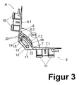
- the rotational adjustment in the first rotation angle range W1 to W2 from an angle W1 (included between the cover wings 4, 5). Fig. 3 ) to an angle W2 included between the covering wings 4, 5 (FIG. Fig. 4 ) is made possible by a pin-slot connection 12, 13.
- two horizontal webs 16, 17 are integrally formed on the inside of the two covering wings 4, 5 in the upper and lower end region of the side cheeks 6, 7 on mutually equal height, wherein on the opposite covering wings 4, 5 facing longitudinal end of these webs 16, 17 at a Abdeckeriel 4 each a pin 16 exits from the top or bottom of the web 16, while on the other Abdeckeriel 5 each an arcuate slot 13 is inserted into the two webs 17, in which each of the pin 16 of the opposite Abdeckeriels 4 engages ,
- the slot width corresponds in each case to the journal diameter, so that the pins 12 in these two slots 13 can move only forcibly in the direction of the longitudinal axis 22 of the elongated holes 13 until it stops against the respective two slot ends 15, these two stop positions in Fig.
- This positively driven displacement movement of the pin 12 in the slot 13 is accompanied by a relative rotation of the two covering wings 4, 5 to each other about a common axis of rotation 14 outside of these pin slot guides 12, 13 (see. Fig. 2 ).
- the predetermined by the longitudinal curvature of the elongated hole 13 relative rotational movement of the covering wings 4, 5 is adapted to the geometry of the covering wings 4, 5, that no rotationally hindering collisions or the formation of unsightly gaps between the Abdeckerieln 4, 5 may occur.
- the side walls 6, 7 of the two covering wings 4, 5 each consist of two wall sections 6.1, 7.1; 6.2, 7.2 built. From a first planar wall section 6.1, 7.1, which is snapped onto the cable duct base, and from an arcuate wall section 6.2, 7.2, which overlaps the arcuate wall section 6.2, 7.2 of the opposite covering wing 4, 5 to form a contact surface.
- a first planar wall section 6.1, 7.1 which is snapped onto the cable duct base
- an arcuate wall section 6.2, 7.2 which overlaps the arcuate wall section 6.2, 7.2 of the opposite covering wing 4, 5 to form a contact surface.
- the inside, horizontal webs 16 not directly, but in each case via support legs 20 to the side wall 6 integrally formed (see. Fig. 3 to 5 ).
- the angle molding 1 according to the invention allows the installer on the other hand, the covering wings 4, 5 even further spread apart until an angle W3 according to Fig. 5 between the Abdeckerieln 4, 5 is obtained.
- the pins 12 of the covering wing 4 thus fill a double function: in the first rotation angle range from W1 to W2, they are still pure guide elements, while in the second rotation angle range from W2 to W3 they act as rotary coupling elements.
- the pin 12th when reaching the stop position at the slot end 15 according to Fig. 4 perpendicular or approximately perpendicular to the mutually facing free end edges 18, 19 of the side walls 6, 7 of the two covering wings 4, 5 are.
Landscapes
- Engineering & Computer Science (AREA)
- Architecture (AREA)
- Civil Engineering (AREA)
- Structural Engineering (AREA)
- Details Of Indoor Wiring (AREA)
Applications Claiming Priority (1)
| Application Number | Priority Date | Filing Date | Title |
|---|---|---|---|
| DE202009013622U DE202009013622U1 (de) | 2009-10-09 | 2009-10-09 | Winkelformteil für Kabelkanäle |
Publications (3)
| Publication Number | Publication Date |
|---|---|
| EP2309612A2 true EP2309612A2 (fr) | 2011-04-13 |
| EP2309612A3 EP2309612A3 (fr) | 2012-04-25 |
| EP2309612B1 EP2309612B1 (fr) | 2013-03-27 |
Family
ID=43558163
Family Applications (1)
| Application Number | Title | Priority Date | Filing Date |
|---|---|---|---|
| EP10013006A Active EP2309612B1 (fr) | 2009-10-09 | 2010-10-01 | Elément de formage d'angle pour canaux de câbles |
Country Status (3)
| Country | Link |
|---|---|
| EP (1) | EP2309612B1 (fr) |
| DE (1) | DE202009013622U1 (fr) |
| ES (1) | ES2413580T3 (fr) |
Cited By (2)
| Publication number | Priority date | Publication date | Assignee | Title |
|---|---|---|---|---|
| EP2639907A1 (fr) * | 2012-03-12 | 2013-09-18 | REHAU AG + Co | Agencement de liaison pour éléments de caniveaux de câbles |
| CN117810896A (zh) * | 2024-02-29 | 2024-04-02 | 山东阳谷恒昌电缆集团有限公司 | 一种置于电缆井内部的电缆架空安装引导装置 |
Citations (2)
| Publication number | Priority date | Publication date | Assignee | Title |
|---|---|---|---|---|
| EP1178251A2 (fr) | 2000-08-03 | 2002-02-06 | Panduit Corporation | Joint d'angle ajustable |
| FR2924867A1 (fr) | 2007-12-06 | 2009-06-12 | Inovac Soc Par Actions Simplif | Accessoire d'angle pour goulottes |
-
2009
- 2009-10-09 DE DE202009013622U patent/DE202009013622U1/de not_active Expired - Lifetime
-
2010
- 2010-10-01 EP EP10013006A patent/EP2309612B1/fr active Active
- 2010-10-01 ES ES10013006T patent/ES2413580T3/es active Active
Patent Citations (2)
| Publication number | Priority date | Publication date | Assignee | Title |
|---|---|---|---|---|
| EP1178251A2 (fr) | 2000-08-03 | 2002-02-06 | Panduit Corporation | Joint d'angle ajustable |
| FR2924867A1 (fr) | 2007-12-06 | 2009-06-12 | Inovac Soc Par Actions Simplif | Accessoire d'angle pour goulottes |
Cited By (3)
| Publication number | Priority date | Publication date | Assignee | Title |
|---|---|---|---|---|
| EP2639907A1 (fr) * | 2012-03-12 | 2013-09-18 | REHAU AG + Co | Agencement de liaison pour éléments de caniveaux de câbles |
| CN117810896A (zh) * | 2024-02-29 | 2024-04-02 | 山东阳谷恒昌电缆集团有限公司 | 一种置于电缆井内部的电缆架空安装引导装置 |
| CN117810896B (zh) * | 2024-02-29 | 2024-05-24 | 山东阳谷恒昌电缆集团有限公司 | 一种置于电缆井内部的电缆架空安装引导装置 |
Also Published As
| Publication number | Publication date |
|---|---|
| EP2309612A3 (fr) | 2012-04-25 |
| ES2413580T3 (es) | 2013-07-17 |
| EP2309612B1 (fr) | 2013-03-27 |
| DE202009013622U1 (de) | 2011-02-24 |
Similar Documents
| Publication | Publication Date | Title |
|---|---|---|
| EP1682735B1 (fr) | Ensemble de profiles avec articulation pour sol | |
| DE102007018309B4 (de) | Verbindung für plattenförmige Bauelemente | |
| EP2113432A1 (fr) | Essuie-glace, en particulier pour véhicules automobiles | |
| DE102007020271A1 (de) | Verbindung für Fußbodenelemente | |
| EP3452667B1 (fr) | Caniveau de drainage superficiel avec une paroi frontale | |
| EP2309612B1 (fr) | Elément de formage d'angle pour canaux de câbles | |
| DE19854552C2 (de) | Rolladenkasten mit Wärmedämmkörper | |
| DE29802616U1 (de) | Eckverbinder für Sockelblenden | |
| AT15365U1 (de) | Verglasungssystem | |
| DE102007030750B4 (de) | Verbindung | |
| EP2578786B1 (fr) | Système avec élément de guidage et dispositif de retenue pour vantaux de porte ou de fenêtre | |
| DE102004013010B3 (de) | Vorrichtung zur Aufnahme von länglichen Gegenständen | |
| DE102021128617B3 (de) | Steckverbinder zum Verbinden von Hohlprofilen | |
| WO2021074280A1 (fr) | Dispositif de ventilation de bâtiment pour installation dans une ouverture traversant une paroi | |
| DE69804669T2 (de) | Balkonverglasung | |
| EP2639907B1 (fr) | Agencement de liaison pour éléments de caniveaux de câbles | |
| DE19618912A1 (de) | Lamelle für ein Blatt eines vorzugsweise auf und ab bewegbaren Rollverschlusses für ein Tor, eine Tür, ein Fenster o. dgl. Öffnung | |
| DE102022205376B4 (de) | Gleitschiene für einen Türantrieb | |
| EP3046194B1 (fr) | Combinaison d'appareil d'installation électrique et d'obturateur à double crochet | |
| DE60012621T2 (de) | Versatztolerantes Winkelstück zum Verbinden von zwei aufeinanderfolgenden Abschnitten eines Sockelleistenkanals oder dergleichen | |
| AT521835B1 (de) | Kabelkanal | |
| DE3633205C1 (de) | Tragevorrichtung fuer quaderfoermige Gehaeuse elektrischer Geraete,insbesondere fuer 19>>-Tischgehaeuse | |
| DE102019009317B4 (de) | Einstückiges Kabelführungsprofil | |
| EP1577478B9 (fr) | Renvoi d'angle avec pièces de guidage | |
| EP0442168B1 (fr) | Disposition de la charnière d'une porte d'armoire de distribution |
Legal Events
| Date | Code | Title | Description |
|---|---|---|---|
| PUAI | Public reference made under article 153(3) epc to a published international application that has entered the european phase |
Free format text: ORIGINAL CODE: 0009012 |
|
| AK | Designated contracting states |
Kind code of ref document: A2 Designated state(s): AL AT BE BG CH CY CZ DE DK EE ES FI FR GB GR HR HU IE IS IT LI LT LU LV MC MK MT NL NO PL PT RO RS SE SI SK SM TR |
|
| AX | Request for extension of the european patent |
Extension state: BA ME |
|
| PUAL | Search report despatched |
Free format text: ORIGINAL CODE: 0009013 |
|
| AK | Designated contracting states |
Kind code of ref document: A3 Designated state(s): AL AT BE BG CH CY CZ DE DK EE ES FI FR GB GR HR HU IE IS IT LI LT LU LV MC MK MT NL NO PL PT RO RS SE SI SK SM TR |
|
| AX | Request for extension of the european patent |
Extension state: BA ME |
|
| RIC1 | Information provided on ipc code assigned before grant |
Ipc: H02G 3/04 20060101AFI20120319BHEP Ipc: H02G 3/06 20060101ALI20120319BHEP |
|
| 17P | Request for examination filed |
Effective date: 20120504 |
|
| GRAP | Despatch of communication of intention to grant a patent |
Free format text: ORIGINAL CODE: EPIDOSNIGR1 |
|
| GRAS | Grant fee paid |
Free format text: ORIGINAL CODE: EPIDOSNIGR3 |
|
| GRAP | Despatch of communication of intention to grant a patent |
Free format text: ORIGINAL CODE: EPIDOSNIGR1 |
|
| GRAA | (expected) grant |
Free format text: ORIGINAL CODE: 0009210 |
|
| AK | Designated contracting states |
Kind code of ref document: B1 Designated state(s): AL AT BE BG CH CY CZ DE DK EE ES FI FR GB GR HR HU IE IS IT LI LT LU LV MC MK MT NL NO PL PT RO RS SE SI SK SM TR |
|
| REG | Reference to a national code |
Ref country code: GB Ref legal event code: FG4D Free format text: NOT ENGLISH |
|
| REG | Reference to a national code |
Ref country code: CH Ref legal event code: EP |
|
| REG | Reference to a national code |
Ref country code: AT Ref legal event code: REF Ref document number: 603932 Country of ref document: AT Kind code of ref document: T Effective date: 20130415 |
|
| REG | Reference to a national code |
Ref country code: IE Ref legal event code: FG4D Free format text: LANGUAGE OF EP DOCUMENT: GERMAN |
|
| REG | Reference to a national code |
Ref country code: DE Ref legal event code: R096 Ref document number: 502010002677 Country of ref document: DE Effective date: 20130529 |
|
| REG | Reference to a national code |
Ref country code: ES Ref legal event code: FG2A Ref document number: 2413580 Country of ref document: ES Kind code of ref document: T3 Effective date: 20130717 |
|
| PG25 | Lapsed in a contracting state [announced via postgrant information from national office to epo] |
Ref country code: LT Free format text: LAPSE BECAUSE OF FAILURE TO SUBMIT A TRANSLATION OF THE DESCRIPTION OR TO PAY THE FEE WITHIN THE PRESCRIBED TIME-LIMIT Effective date: 20130327 Ref country code: SE Free format text: LAPSE BECAUSE OF FAILURE TO SUBMIT A TRANSLATION OF THE DESCRIPTION OR TO PAY THE FEE WITHIN THE PRESCRIBED TIME-LIMIT Effective date: 20130327 Ref country code: NO Free format text: LAPSE BECAUSE OF FAILURE TO SUBMIT A TRANSLATION OF THE DESCRIPTION OR TO PAY THE FEE WITHIN THE PRESCRIBED TIME-LIMIT Effective date: 20130627 Ref country code: BG Free format text: LAPSE BECAUSE OF FAILURE TO SUBMIT A TRANSLATION OF THE DESCRIPTION OR TO PAY THE FEE WITHIN THE PRESCRIBED TIME-LIMIT Effective date: 20130627 |
|
| REG | Reference to a national code |
Ref country code: LT Ref legal event code: MG4D |
|
| PG25 | Lapsed in a contracting state [announced via postgrant information from national office to epo] |
Ref country code: GR Free format text: LAPSE BECAUSE OF FAILURE TO SUBMIT A TRANSLATION OF THE DESCRIPTION OR TO PAY THE FEE WITHIN THE PRESCRIBED TIME-LIMIT Effective date: 20130628 Ref country code: FI Free format text: LAPSE BECAUSE OF FAILURE TO SUBMIT A TRANSLATION OF THE DESCRIPTION OR TO PAY THE FEE WITHIN THE PRESCRIBED TIME-LIMIT Effective date: 20130327 Ref country code: SI Free format text: LAPSE BECAUSE OF FAILURE TO SUBMIT A TRANSLATION OF THE DESCRIPTION OR TO PAY THE FEE WITHIN THE PRESCRIBED TIME-LIMIT Effective date: 20130327 Ref country code: LV Free format text: LAPSE BECAUSE OF FAILURE TO SUBMIT A TRANSLATION OF THE DESCRIPTION OR TO PAY THE FEE WITHIN THE PRESCRIBED TIME-LIMIT Effective date: 20130327 |
|
| REG | Reference to a national code |
Ref country code: NL Ref legal event code: VDEP Effective date: 20130327 |
|
| PG25 | Lapsed in a contracting state [announced via postgrant information from national office to epo] |
Ref country code: HR Free format text: LAPSE BECAUSE OF FAILURE TO SUBMIT A TRANSLATION OF THE DESCRIPTION OR TO PAY THE FEE WITHIN THE PRESCRIBED TIME-LIMIT Effective date: 20130327 |
|
| PG25 | Lapsed in a contracting state [announced via postgrant information from national office to epo] |
Ref country code: RO Free format text: LAPSE BECAUSE OF FAILURE TO SUBMIT A TRANSLATION OF THE DESCRIPTION OR TO PAY THE FEE WITHIN THE PRESCRIBED TIME-LIMIT Effective date: 20130327 Ref country code: PT Free format text: LAPSE BECAUSE OF FAILURE TO SUBMIT A TRANSLATION OF THE DESCRIPTION OR TO PAY THE FEE WITHIN THE PRESCRIBED TIME-LIMIT Effective date: 20130729 Ref country code: NL Free format text: LAPSE BECAUSE OF FAILURE TO SUBMIT A TRANSLATION OF THE DESCRIPTION OR TO PAY THE FEE WITHIN THE PRESCRIBED TIME-LIMIT Effective date: 20130327 Ref country code: IS Free format text: LAPSE BECAUSE OF FAILURE TO SUBMIT A TRANSLATION OF THE DESCRIPTION OR TO PAY THE FEE WITHIN THE PRESCRIBED TIME-LIMIT Effective date: 20130727 Ref country code: SK Free format text: LAPSE BECAUSE OF FAILURE TO SUBMIT A TRANSLATION OF THE DESCRIPTION OR TO PAY THE FEE WITHIN THE PRESCRIBED TIME-LIMIT Effective date: 20130327 Ref country code: CZ Free format text: LAPSE BECAUSE OF FAILURE TO SUBMIT A TRANSLATION OF THE DESCRIPTION OR TO PAY THE FEE WITHIN THE PRESCRIBED TIME-LIMIT Effective date: 20130327 Ref country code: EE Free format text: LAPSE BECAUSE OF FAILURE TO SUBMIT A TRANSLATION OF THE DESCRIPTION OR TO PAY THE FEE WITHIN THE PRESCRIBED TIME-LIMIT Effective date: 20130327 |
|
| PG25 | Lapsed in a contracting state [announced via postgrant information from national office to epo] |
Ref country code: CY Free format text: LAPSE BECAUSE OF FAILURE TO SUBMIT A TRANSLATION OF THE DESCRIPTION OR TO PAY THE FEE WITHIN THE PRESCRIBED TIME-LIMIT Effective date: 20130327 Ref country code: PL Free format text: LAPSE BECAUSE OF FAILURE TO SUBMIT A TRANSLATION OF THE DESCRIPTION OR TO PAY THE FEE WITHIN THE PRESCRIBED TIME-LIMIT Effective date: 20130327 |
|
| PG25 | Lapsed in a contracting state [announced via postgrant information from national office to epo] |
Ref country code: DK Free format text: LAPSE BECAUSE OF FAILURE TO SUBMIT A TRANSLATION OF THE DESCRIPTION OR TO PAY THE FEE WITHIN THE PRESCRIBED TIME-LIMIT Effective date: 20130327 |
|
| PLBE | No opposition filed within time limit |
Free format text: ORIGINAL CODE: 0009261 |
|
| STAA | Information on the status of an ep patent application or granted ep patent |
Free format text: STATUS: NO OPPOSITION FILED WITHIN TIME LIMIT |
|
| 26N | No opposition filed |
Effective date: 20140103 |
|
| REG | Reference to a national code |
Ref country code: DE Ref legal event code: R097 Ref document number: 502010002677 Country of ref document: DE Effective date: 20140103 |
|
| BERE | Be: lapsed |
Owner name: TEHALIT G.M.B.H. Effective date: 20131031 |
|
| PG25 | Lapsed in a contracting state [announced via postgrant information from national office to epo] |
Ref country code: MC Free format text: LAPSE BECAUSE OF FAILURE TO SUBMIT A TRANSLATION OF THE DESCRIPTION OR TO PAY THE FEE WITHIN THE PRESCRIBED TIME-LIMIT Effective date: 20130327 |
|
| REG | Reference to a national code |
Ref country code: IE Ref legal event code: MM4A |
|
| PG25 | Lapsed in a contracting state [announced via postgrant information from national office to epo] |
Ref country code: BE Free format text: LAPSE BECAUSE OF NON-PAYMENT OF DUE FEES Effective date: 20131031 |
|
| PG25 | Lapsed in a contracting state [announced via postgrant information from national office to epo] |
Ref country code: IE Free format text: LAPSE BECAUSE OF NON-PAYMENT OF DUE FEES Effective date: 20131001 |
|
| PG25 | Lapsed in a contracting state [announced via postgrant information from national office to epo] |
Ref country code: SM Free format text: LAPSE BECAUSE OF FAILURE TO SUBMIT A TRANSLATION OF THE DESCRIPTION OR TO PAY THE FEE WITHIN THE PRESCRIBED TIME-LIMIT Effective date: 20130327 |
|
| REG | Reference to a national code |
Ref country code: CH Ref legal event code: PL |
|
| GBPC | Gb: european patent ceased through non-payment of renewal fee |
Effective date: 20141001 |
|
| PG25 | Lapsed in a contracting state [announced via postgrant information from national office to epo] |
Ref country code: TR Free format text: LAPSE BECAUSE OF FAILURE TO SUBMIT A TRANSLATION OF THE DESCRIPTION OR TO PAY THE FEE WITHIN THE PRESCRIBED TIME-LIMIT Effective date: 20130327 |
|
| PG25 | Lapsed in a contracting state [announced via postgrant information from national office to epo] |
Ref country code: RS Free format text: LAPSE BECAUSE OF FAILURE TO SUBMIT A TRANSLATION OF THE DESCRIPTION OR TO PAY THE FEE WITHIN THE PRESCRIBED TIME-LIMIT Effective date: 20130627 Ref country code: LU Free format text: LAPSE BECAUSE OF NON-PAYMENT OF DUE FEES Effective date: 20131001 Ref country code: HU Free format text: LAPSE BECAUSE OF FAILURE TO SUBMIT A TRANSLATION OF THE DESCRIPTION OR TO PAY THE FEE WITHIN THE PRESCRIBED TIME-LIMIT; INVALID AB INITIO Effective date: 20101001 Ref country code: MK Free format text: LAPSE BECAUSE OF FAILURE TO SUBMIT A TRANSLATION OF THE DESCRIPTION OR TO PAY THE FEE WITHIN THE PRESCRIBED TIME-LIMIT Effective date: 20130327 Ref country code: CH Free format text: LAPSE BECAUSE OF NON-PAYMENT OF DUE FEES Effective date: 20141031 Ref country code: GB Free format text: LAPSE BECAUSE OF NON-PAYMENT OF DUE FEES Effective date: 20141001 Ref country code: LI Free format text: LAPSE BECAUSE OF NON-PAYMENT OF DUE FEES Effective date: 20141031 |
|
| PG25 | Lapsed in a contracting state [announced via postgrant information from national office to epo] |
Ref country code: MT Free format text: LAPSE BECAUSE OF FAILURE TO SUBMIT A TRANSLATION OF THE DESCRIPTION OR TO PAY THE FEE WITHIN THE PRESCRIBED TIME-LIMIT Effective date: 20130327 |
|
| REG | Reference to a national code |
Ref country code: FR Ref legal event code: PLFP Year of fee payment: 6 |
|
| REG | Reference to a national code |
Ref country code: FR Ref legal event code: PLFP Year of fee payment: 7 |
|
| REG | Reference to a national code |
Ref country code: AT Ref legal event code: MM01 Ref document number: 603932 Country of ref document: AT Kind code of ref document: T Effective date: 20151001 |
|
| PG25 | Lapsed in a contracting state [announced via postgrant information from national office to epo] |
Ref country code: AT Free format text: LAPSE BECAUSE OF NON-PAYMENT OF DUE FEES Effective date: 20151001 |
|
| REG | Reference to a national code |
Ref country code: FR Ref legal event code: PLFP Year of fee payment: 8 |
|
| REG | Reference to a national code |
Ref country code: FR Ref legal event code: PLFP Year of fee payment: 9 |
|
| PG25 | Lapsed in a contracting state [announced via postgrant information from national office to epo] |
Ref country code: AL Free format text: LAPSE BECAUSE OF FAILURE TO SUBMIT A TRANSLATION OF THE DESCRIPTION OR TO PAY THE FEE WITHIN THE PRESCRIBED TIME-LIMIT Effective date: 20130327 |
|
| P01 | Opt-out of the competence of the unified patent court (upc) registered |
Effective date: 20230606 |
|
| PGFP | Annual fee paid to national office [announced via postgrant information from national office to epo] |
Ref country code: DE Payment date: 20251029 Year of fee payment: 16 |
|
| PGFP | Annual fee paid to national office [announced via postgrant information from national office to epo] |
Ref country code: IT Payment date: 20251021 Year of fee payment: 16 |
|
| PGFP | Annual fee paid to national office [announced via postgrant information from national office to epo] |
Ref country code: FR Payment date: 20251027 Year of fee payment: 16 |
|
| PGFP | Annual fee paid to national office [announced via postgrant information from national office to epo] |
Ref country code: ES Payment date: 20251103 Year of fee payment: 16 |