EP2309679B1 - Procédé et système d'optimisation de la couche réseau radio en vue de l'interconnexion entre réseaux et procédé d'interconnexion entre le réseau radio et le réseau cable - Google Patents
Procédé et système d'optimisation de la couche réseau radio en vue de l'interconnexion entre réseaux et procédé d'interconnexion entre le réseau radio et le réseau cable Download PDFInfo
- Publication number
- EP2309679B1 EP2309679B1 EP11153330.3A EP11153330A EP2309679B1 EP 2309679 B1 EP2309679 B1 EP 2309679B1 EP 11153330 A EP11153330 A EP 11153330A EP 2309679 B1 EP2309679 B1 EP 2309679B1
- Authority
- EP
- European Patent Office
- Prior art keywords
- network
- interface
- layer
- server
- radio
- Prior art date
- Legal status (The legal status is an assumption and is not a legal conclusion. Google has not performed a legal analysis and makes no representation as to the accuracy of the status listed.)
- Not-in-force
Links
Images


Classifications
-
- H—ELECTRICITY
- H04—ELECTRIC COMMUNICATION TECHNIQUE
- H04W—WIRELESS COMMUNICATION NETWORKS
- H04W92/00—Interfaces specially adapted for wireless communication networks
- H04W92/04—Interfaces between hierarchically different network devices
- H04W92/045—Interfaces between hierarchically different network devices between access point and backbone network device
-
- H—ELECTRICITY
- H04—ELECTRIC COMMUNICATION TECHNIQUE
- H04Q—SELECTING
- H04Q11/00—Selecting arrangements for multiplex systems
- H04Q11/0001—Selecting arrangements for multiplex systems using optical switching
- H04Q11/0062—Network aspects
- H04Q11/0067—Provisions for optical access or distribution networks, e.g. Gigabit Ethernet Passive Optical Network (GE-PON), ATM-based Passive Optical Network (A-PON), PON-Ring
-
- H—ELECTRICITY
- H04—ELECTRIC COMMUNICATION TECHNIQUE
- H04W—WIRELESS COMMUNICATION NETWORKS
- H04W88/00—Devices specially adapted for wireless communication networks, e.g. terminals, base stations or access point devices
- H04W88/12—Access point controller devices
-
- H—ELECTRICITY
- H04—ELECTRIC COMMUNICATION TECHNIQUE
- H04W—WIRELESS COMMUNICATION NETWORKS
- H04W92/00—Interfaces specially adapted for wireless communication networks
- H04W92/04—Interfaces between hierarchically different network devices
- H04W92/14—Interfaces between hierarchically different network devices between access point controllers and backbone network device
Definitions
- the present invention relates to the field of communication technology, in particular, to a method and a system for optimizing a radio network layer to implement network interconnection, and a method for interconnection between a radio network and a wired network.
- the optical access network (collectively referred to as FTTx) is classified into Fiber To The Home (FTTH), Fiber To The Building (FTTB), Fiber To The Curb (FTTC) and the like, according to the location of the optical network unit (ONU).
- FTTx Fiber To The Home
- FTTB Fiber To The Building
- FTTC Fiber To The Curb
- ONU optical network unit
- the formal name of the optical access network is fiber in the loop (FITL). Due to the high bandwidth, the OAN is capable of developing Triple Play in a better way, i.e., a service for simultaneously transmitting voices, data, and multimedia videos.
- the OAN mainly employs a passive optical network (PON) technology.
- PON passive optical network
- transmission resources can be conveniently obtained.
- the FTTH has become an effective supplementary means for 3G IP transmission base stations.
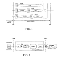
- FIG. 1 shows a network architecture of the OAN
- FIG. 2 shows a specific OAN reference architecture
- the OAN is formed by a customer premises network (CPN), an access network, and a service node function (SNF).
- the main network elements of the CPN and the access network include: an optical line terminal (OLT), an optical distribution network (ODN), an optical network unit/optical network terminal (ONU/ONT), and an adaptation function (AF).
- the AF is an optional device, which mainly provides a conversion between an ONU/ONT interface and a user network interface (UNI).
- the AF may also be built in the ONU, and in this case, a reference point a can be omitted.
- the AF may also be arranged behind the OLT to provide a conversion between an OLT interface and a service node interface (SNI).
- SNI service node interface
- the AF may either be considered as a function of the CPN or a function of the access network, in which T is a reference point for the UNI interface, and V is a reference point for the SNI interface.
- the OLT provides a network interface for the ODN and is connected to one or more ODNs.
- the ODN provides a transmission means for the OLT and the ONU.
- the ONU provides a user side interface for the OAN and is connected to the ODN.
- a customer premises equipment is connected to the AF via the UNI interface (for example, a DSL line).
- the AF converts a packet format from a format of the UNI interface into a format of an interface a (for example, an Ethernet link) capable of being connected to the ONU.
- the ONU converts the packet into a format capable of being delivered on the ODN (for example, EPON encapsulation, or GPON encapsulation based on generic framing).
- the OLT converts the packet into a packet format of the SNI interface (for example, Ethernet link), and then accesses a service node.
- the 3G/2G radio communication system employs a similar structure, which includes a radio access network (RAN) and a core network (CN).
- the RAN is adapted to process all the radio related functions, whereas the CN processes all the voice calls and data connections within the radio communication system, and implements the switching and routing functions with an external network.
- the CN is logically divided into a circuit switched (CS) domain and a packet switched (PS) domain.
- CS circuit switched
- PS packet switched
- the RAN and the CN, together with a mobile station (MS), constitute the entire 3G/2G radio communication network, and the system reference architecture thereof is shown in FIG. 3 .
- a base station is called a base transceiver station (BTS) in GSM/GPRS/CDMA/CDMA2000, and it is called a Node B in WCDMA/TD-SCDMA.
- BSC base station controller
- RNC radio network controller
- PCF packet control function
- PDSN packet data serving node
- the PCF may be allocated together with the BSC or separately.
- the UTRAN uses the Iu serial interfaces, which includes Iu, Iur, and Iub interfaces.
- the protocol stacks are classified into a corresponding radio network layer (RNL) and a transport network layer (TNL) according to the general protocol model at the UTRAN interface.
- the Iu interface is an interface for connecting the UTRAN to the CN, which is an open standard interface with the RANAP as the control plane protocol and the GTP protocol as the user plane protocol.
- the Iur interface is an interface for connecting one RNC with another, which is an exclusive interface for the UMTS system, and is adapted to mobile management of the MS in the RAN.
- the Iur interface is also an open standard interface with the RNSAP as the control plane protocol and the Iur FP as the user plane protocol.
- the Iub interface is an interface for connecting the Node B to the RNC, which is also an open standard interface, and takes the NBAP as the control plane protocol and the Iub FP as the user plane protocol.
- the Node B is a BS (i.e., a radio transceiver) for the WCDMA system, and includes a radio transceiver and a base band processing unit.
- the Node B is interconnected with the RNC via the standard Iub interface and mainly adapted to complete the processing of the physical layer protocol at the Uu interface.
- the main functions of the Node B mainly lie in spreading, modulating, channel coding, despreading, demodulating, and channel decoding, as well as interconversion between the base band signal and the radio frequency (RF) signal.
- the RNC is adapted to control the radio resources of the UTRAN and has the main functions of connection establishment, disconnection, handover, macro diversity combination, radio resource management and control.
- the RNC includes the following functions: (1) the broadcast distribution and system access control; (2) the mobility management, such as handover and RNC relocation; and (3) the radio resource management and control, such as macro diversity combination, power control, and radio bearer distribution.
- the radio interface protocol stack architecture between a user equipment (UE) and the UTRAN includes a plurality of protocols distributed and implemented in different nodes in the RAN.
- a radio resource control (RRC) protocol is implemented in the UE and RNC, and mainly adapted to implement the RRC connection management, radio bearer management, paging/broadcasting, mobility management, and other functions.
- the RRC protocol is responsible for configuring parameter information of the other protocol entities in the radio interface protocol stack.
- a radio link control (RLC) protocol is implemented in the UE and the RNC, and mainly adapted to implement the data transmission function of user data and provides three data transmission modes respectively suitable for transmitting service data with different QoS requirements.
- a media access control (MAC) protocol is generally implemented in the UE and RNC and responsible for selecting suitable transmission formats for the user data and realizing the mapping from logical channels to transport channels.
- the Node B supports the MAC protocol.
- a packet data convergence protocol (PDCP) is implemented in the UE and RNC and has the following functions. The PDCP protocol respectively performs header compression and decompression of the IP data stream in the transmitting and receiving entities, for example, the TCP/IP and RTP/UDP/IP header compression manners are corresponding to particular combinations of network layers, transport layers, or upper layer protocols.
- the PDCP protocol further has the function of user data transmission, that is, forwarding the PDCP-SDU from the non-access stratum to the RLC layer, in which if the lossless SRNS relocation function is supported, the PDCP-SDU and the corresponding serial number are forwarded, so as to multiplex a plurality of different RBs into the same RLC entity.
- a broadcast/multicast control protocol has the functions of storing broadcast messages of the cell, monitoring the traffic flow and requesting radio resources for a cell broadcast service (CBS), scheduling BMC messages, sending the BMC messages to the UE, transmitting the cell broadcast messages to a high layer (the NAS).
- CBS cell broadcast service
- NAS high layer
- the outer loop power control algorithm cannot rapidly adjust the SIRtarget according to changes of the airlink. Meanwhile, the cell load information relies on the periodical report from the Node B, so that the information hysteresis exists, and as a result, the load information obtained by the RNC is not in real time.
- the protocol structure with all the access high layers being allocated in the RNC is not suitable for high-speed data transmission, since such a protocol structure cannot guarantee high speed and high efficiency of the data transmission upon adopting the technologies similar to self-adaptive coordination and feedback control. Thus, it is difficult to meet the requirements of the high-speed data transmission.
- a hybrid fiber-coaxial (HFC) access network (DOCSIS) is a bidirectional interactive broadband network based on the cable television coaxial network, which reserves the traditional analogue transmission mode and also makes full use of the current cable television coaxial cable resources, for providing various services for users such as phone calls, broadcasting and television, video on demand, Internet access, videoconference, and data, without allocating new distribution networks. Therefore, the DOCSIS possesses low cost, wideband, and multi-service properties, which will become a desirable solution for the last mile broadband access.
- the DOCSIS is a CableLabs standard for the bidirectional interactive HFC access network
- the PacketCable standard is a DOCSIS-based multi-service operator (MSO) broadband standard.
- the PacketCable is divided into an HFC access network, a CPN, and a managed IP network, and the PacketCable reference architecture based on the HFC access network as shown in FIG. 5 .
- the main network elements of the HFC access network and the CPN include: a cable modem terminal system (CMTS), an HFC transport network (HFC/Cable Network), a cable modem (CM), a multimedia terminal adapter (MTA) (omitted in the figure) and the like.
- CMTS cable modem terminal system
- HFC/Cable Network HFC transport network
- CM cable modem
- MTA multimedia terminal adapter
- the CMCI is a reference point for the CPE and the CM in the CPN;
- the CMRFI is a reference point between the CM and the HFC/Cable Network;
- the CMTS-NSI is an Ethernet aggregation reference point between the CMTS and the managed IP network.
- the managed IP network and the CPE can employ Layer 2 network bridging technology, and may also employ IP Layer 3 routing technology.
- FIG. 6 is a schematic view of a typical WCDMA networking transmission mode.
- a user leaves the E1 networking via the Iub interface of the WCDMA.
- the WCDMA provides a maximum bandwidth of merely 2 Mbps for each user.
- the Iub transmission of WCDMA R99 employs an ATM transmission technology.
- the ATM can be carried on the TDM transmission, for example, on the E1/T1 (E1 transmission rate is 2 MHz, and T1 transmission rate is 1.5 MHz).
- the BS needs to multilink bundle the E1/T1, i.e., employing an inverse multiplexing over ATM (IMA) technology.
- IMA inverse multiplexing over ATM
- the radio network transmission has become an urgent problem to be solved by the operators.
- the operators are confronted with the selection of either establishing their own transmission networks or seeking other inexpensive alternative technologies.
- Document 3GPP TSG-RAN2 draft No. R2-052921 provides a proposal for E-UTRAN Architecture and Protocols. Furthermore, it discloses user plane protocol stack of proposed architecture and control plane protocol stack of proposed architecture.
- Document 3GPP TSG SA WG2/TSG RAN WG3 draft No. SRJ-050053 discloses a high level description of a scenario that aims to meet the requirements on an evolved system.
- the architecture according to the document is split in a control plane and a transport plane.
- FAN Future Access Networks
- the present invention relates to a system as described in claim 1, and an apparatus as described in claim 16. Preferred embodiments are described in the dependent claims.
- a system for optimizing a radio network layer to implement a network interconnection which includes a wireless-server (W-Server) and an apparatus BS+WA, the wireless-server, adapted to has control plane functions of Serving GPRS Support Node (SGSN), control plane functions of Gateway GPRS Support Node (GGSN) and part of control plane functions of Radio Network Controller (RNC), wherein the part of control plane functions of RNC comprises the function of Broadcast Distribution and the function of Relocation Control, and the network element BS+WA, adapted to complete the processing of Media Access Control (MAC), Radio Link Control (RLC), Packet Data Convergence Protocol (PDCP) and part of Radio Resource Control (RRC), wherein the part of RRC comprises the function of Cell-specific Radio Resource Management (CS-RRM) and the function of Handover Control (HO Control); wherein the apparatus BS+WA and the W-Server are interconnected by an Iub-C interface and the Iub
- MAC Media Access Control
- RLC Radio Link Control
- PDCP Pack
- an apparatus BS+WA for an interconnection between a BS and a wired network is provided, the apparatus BS+WA is adapted to complete the processing of Media Access Control (MAC), Radio Link Control (RLC), Packet Data Convergence Protocol (PDCP) and part of Radio Resource Control (RRC), wherein the part of RRC comprises the function of Cell-specific Radio Resource Management (CS-RRM) and the function of Handover Control (HO Control); wherein the apparatus BS+WA is further adapted to interconnect with a wireless-server (W-Server) by an Iub-C interface and the Iub-C comprises NBAP.
- W-Server wireless-server
- a radio access network in order to implement a network interconnection through moving downward the radio network layer, the functions of a radio access network (RAN) are separated, and the following functional units are defined, namely, a base station (BS), a wireless adaptor (WA), and a radio access network server (RAN-Server).
- BS base station
- WA wireless adaptor
- RAN-Server radio access network server
- the functions of the BS, WA, and RAN-Server are classified as follows.
- Table 1 Functional decomposition of the BS, WA, and RAN-Server Function BS WA (with functions moved downward) RAN-Server Physical Layer (PHY) Mandatory Media Access Control (MAC) Mandatory Radio Link Control (RLC) Mandatory Broadcast/Multicast Control (BMC) Optional Optional Packet Data Convergence Protocol (PDCP) Mandatory Radio Resource Control (RRC) • Multi-cell Radio Resource Management (MC-RRM) Optional • Cell-specific Radio Resource Management (CS-RRM) Mandatory • Broadcast Distribution Mandatory • Handover Control (HO Control) Mandatory • Paging Control Optional • Admission Control Optional • Intra-cell Control Optional • Inter-cell Control Optional Relocation Control Mandatory QoS Scheduling Optional RANAP Message Forwarding Optional RNSAP Message Forwarding
- FIG. 7 A new architecture of a radio network according to an example, not comprising all features being necessary for implementing the present invention is shown in FIG. 7 .
- an interface between a network element UE and a network element BS+WA employs an existing interface Uu originally configured between the UE and a UTRAN, and an interface Iub between a Node B and a radio network controller (RNC) no longer exists.
- RNC radio network controller
- a newly defined interface Iub-C is employed between the network element BS+WA and the RAN-Server.
- An interface Iu-D between the network element BS+WA and a core network (CN) employs a user plane of an existing interface Iu originally configured between the RNC and an SGSN.
- CN core network
- An interface Iu-C between the RAN-Server and the CN employs a control plane of the existing interface Iu originally configured between the RNC and the SGSN.
- a control plane of an existing interface Iur originally configured between the RNCs is employed between the RAN-Servers.
- an additional interface between one network element BS+WA and another BS+WA employs an existing Iur interface originally configured between the RNCs. Definitions of enhanced mobile network interfaces with radio interface functions moved downward and a protocol stack thereof are shown in FIG. 8 .
- a control function and a bearer function are further decomposed for the PS domain of the CN.
- One way of functional decomposition is to define functional units: a serving GPRS support node server (SGSN-Server), a serving GPRS support node gateway (SGSN-GW), a gateway GPRS support node server (GGSN-Server), and a gateway GPRS support node gateway (GGSN-GW).
- the SGSN-Server has control plane functions of the original SGSN, including mobility management, connection management, session management, and the like.
- the SGSN-GW has user plane functions of the original SGSN.
- the GGSN-Server has control plane functions of the original GGSN.
- the GGSN-GW has user plane functions of the original GGSN.
- FIG. 9 a radio network architecture according to an example, not comprising all features being necessary for implementing the present invention is shown in FIG. 9 .
- the RAN is identical to that in FIG. 7 .
- an interface Iu-D between the SGSN-GW and the BS+WA employs a user plane of an existing interface Iu originally configured between the RNC and the SGSN.
- An interface Iu-C between the SGSN-Server and the RAN-Server employs a control plane of the existing interface Iu originally configured between the RNC and the SGSN.
- An interface Gn-D between the SGSN-GW and the GGSN-GW employs a user plane of an existing interface Gn originally configured between the GGSN and the SGSN.
- An interface Gn-C between the SGSN-Server and the GGSN-Server employs a control plane of the existing interface Gn originally configured between the GGSN and the SGSN.
- An interface between the SGSN-Server and the SGSN-GW employs Megaco of IETF or H.248 of ITU-T, or a completely new protocol stack. The SGSN-Server manages the SGSN-GW via Megaco/H.248.
- An interface between the GGSN-Server and the GGSN-GW employs the Megaco of IETF or H.248 of ITU-T, or a completely new protocol stack.
- the GGSN-Server manages the GGSN-GW via Megaco/H.248, as shown in FIG. 8(c) .
- functions of the PS domain of the CN are decomposed in a manner of defining functional units: an integrated GPRS support node server (IGSN-Server) and an integrated GPRS support node gateway (IGSN-GW).
- IGSN-Server has control plane functions of both the original SGSN and GGSN.
- IGSN-GW has user plane functions of both the original SGSN and GGSN.
- FIG. 10 a new radio network architecture of the present invention is shown in FIG. 10 .
- the RAN is identical to that in FIG. 7 .
- an interface Iu-D between the IGSN-GW and the BS+WA employs a user plane of an existing interface Iu originally configured between the RNC and the SGSN.
- An interface Iu-C between the IGSN-Server and the RAN-Server employs a control plane of the existing interface Iu originally configured between the RNC and the SGSN.
- An interface between the IGSN-Server and the IGSN-GW employs Megaco of IETF or H.248 of ITU-T, or a completely new protocol stack.
- the IGSN-Server manages the IGSN-GW via Megaco/H.248.
- FIG. 11 another radio network architecture according to an example, not comprising all features being necessary for implementing the present invention is shown in FIG. 11 .
- the RAN-Server and the IGSN-Server are integrated into one network element, which is referred to as a wireless-server (W-Server).
- the IGSN-GW remains unchanged.
- a newly defined interface Iub-C is employed between the BS+WA and the W-Server.
- An interface between the W-Server and the IGSN-GW employs Megaco of IETF or H.248 of ITU-T, or a completely new protocol stack.
- the W-Server manages the IGSN-GW via Megaco.248.
- An interface Iur-C between the W-Servers employs a control plane of an existing interface Iur originally configured between the RNCs.
- FIG. 12 a method for an interconnection between an optical access network (OAN) and a radio network according to a first example, not comprising all features being necessary for implementing the present invention is shown in FIG. 12 .
- the BS and WA of a 3G/2G radio communication network are interconnected with the OAN at a reference point (a) within the OAN via an AF.
- the RAN-Server and the CN are interconnected with an optical line terminal (OLT) at a reference point v within the OAN.
- OLT optical line terminal
- the copper wire resources in the building are directly utilized when allocating 3G/2G radio communication network equipments in the building, and the 3G/2G radio communication network equipments access the OAN network via optical network units (ONUs), thereby avoiding the additional wiring for the radio communication network and reducing the construction cost of the 3G/2G access network.
- the solution belongs to a tight-coupling solution.
- the network elements BS and WA are integrated into one network element, and the integrated network element BS+WA may be separated from the AF and interconnected with the AF at a reference point T.
- the network elements BS, WA, and AF are integrated into one network element.
- the RAN-Server and the network element OLT may be integrated into one network element.
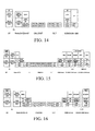
- the protocol stack under the path of UE->Node B->ONU->OLT->Core Network has a user plane shown in FIGS. 13 and 14 , and a control plane shown in FIGs. 15 and 16 .
- the functional decomposition of the BS, WA, and RAN-Server is shown in Table 1.
- the CN includes the SGSN and the GGSN.
- the SGSN and the GGSN may also be integrated into a new network element IGSN.
- the CN may also be accomplished according to the solution shown in FIGs. 9 and 10 .
- the UE first establishes a radio resource control (RRC) connection via a control plane protocol stack and then starts to establish a radio access bearer (RAB) after negotiating with the CN during the data communication.
- RRC radio resource control
- RAB radio access bearer
- RB user plane radio bearer
- the UE establishes an RRC connection with the UTRAN and then establishes a signaling connection with the CN via the RNC, which is also referred to as "NAS signaling establishment process" and suitable for exchanging the NAS information between signaling of the UE and that of the CN, for example, authentication, service request, and connection establishment.
- RNC radio access control network
- the application layer data of the UE is encapsulated into an IP packet or PPP packet and then transmitted to a PDCP protocol of a radio network layer (RNL).
- RNL radio network layer
- the PDCP protocol compresses a header of the data packet and delivers the compressed data to an RLC/MAC of the RNL.
- the RLC/MAC protocol adds an RLC/MAC header to the data packet after receiving and processing the data packet, and then transmits the data packet to a radio frequency layer (RFL) of WCDMA.
- RFL radio frequency layer
- the RFL performs encoding, modulation, and other operations on the received data packet and transmits the processed data packet to the UTRAN via the Uu interface.
- An RFL layer of WCDMA of the BS+WA in the UTRAN receives the data and transmits the data to a MAC/RLC protocol of the RNL. Then, the MAC/RLC protocol removes the protocol headers sequentially, reassembles and combines the data, and then transmits the data to the PDCP protocol of the RNL. The PDCP protocol decompresses the compressed data packet headers. Then, the network element BS+WA forwards the decompressed data to the CN through a GTP tunnel via the interface Iu-D.
- the GTP tunnel protocol, UDP, and IP at the interface Iu-D between the WA and the CN may be directly carried on the OAN network.
- the OAN network between the WA and the CN may employ a Layer 2 bridging technology (for example, Ethernet bridging). That is, the AF, ONU/ONT, and OLT are all Layer 2 network elements.
- a Layer 3 routing technology (for example, IP Layer 3 routing) is employed between the WA and the CN. That is, the AF, ONU/ONT, and OLT are all Layer 3 network elements.
- the network element BS+WA divides the GTP/UDP/IP packet into LNK frames and then carries them on the physical layer between the Node B and the AF and transmits them to the AF.
- the AF converts the LNK frames into ONU LNK frames and then carries them on the physical layer between the ONU/ONT and the AF and transmits them to the ONU/ONT.
- the ONU/ONT converts the ONU/ONT LNK frames into ODN LNK frames suitable for optical transmission, then performs an electro-optical conversion to carry them on the ODN physical layer, and transmits them to the OLT via an optical fiber.
- the OLT PHY performs a photoelectric conversion to obtain the ODN LNK frames and then converts the ODN LNK frames into the LNK frames and transmits them to the CN for further processing.
- the SGSN/SGSN-GW receives the data from the GTP tunnel of the interface Iu-D, performs processing on transport network layer and radio network layer of the interface Iu-D, and then transmits the processed data to the GGSN/GGSN-GW via the interface Gn/Gn-D through the GTP tunnel.
- the data received by the GGSN/GGSN-GW through the GTP tunnel via the interface Gn/Gn-D is the IP packet or PPP packet from the UE.
- the GGSN/GGSN-GW transmits the data in the form of an IP packet or PPP protocol packet to an external network via an interface Gi.
- the IGSN/IGSN-GW performs processing on the transport network layer and radio network layer of the interface Iu-D.
- the data received through the GTP tunnel of the interface Iu-D is the IP packet or PPP packet from the UE.
- the IGSN/IGSN-GW transmits the processed data to the external network in the form of an IP packet or PPP protocol packet.
- the downlink is similar to the uplink, except that the PDCP protocol in the BS+WA is responsible for compressing the header of the downlink data and the PDCP protocol in the UE is responsible for decompressing the header of the downlink data.
- the RRC of the UE encapsulates a GMM/SM/SMS message or a signaling message of the current layer into a data packet and transmits the data packet to the RLC/MAC of the RNL.
- the RLC/MAC protocol adds an RLC/MAC header to the data packet after receiving and processing the data packet, and then transmits the data packet to an RFL layer of WCDMA.
- the RFL layer performs encoding, modulation, and other operations on the received data packet and then transmits the data packet to the UTRAN via the Uu interface.
- An RFL layer of WCDMA of the BS+WA in the UTRAN receives and transmits the data to a MAC/RLC protocol of the RNL.
- the MAC/RLC protocol removes the protocol headers sequentially, reassembles and combines the data, and then transmits the data to the RRC protocol of the RNL.
- the RRC protocol directly resolves the signaling message and performs corresponding processing such as connection establishment, and measurement report.
- the RRC of the BS+WA directly carries the corresponding signaling message via the radio network layer (for example, FP) and transport network layer (for example, IP/LNK/PHY) of the interface Iub-C, and informs the RRC layer of the RAN-Server about the processing result, and then forwards the signaling message to the CN through the RAN-Server via the radio network layer (for example, NANAP) and transport network layer (for example, SCCP/M3UA/SCTP/IP/LNK/PHY, and M3UA/SCTP/IP is the signaling bearer layer in the figure) of the interface lu-C.
- the radio network layer for example, FP
- transport network layer for example, IP/LNK/PHY
- transport network layer for example, SCCP/M3UA/SCTP/IP/LNK/PHY
- M3UA/SCTP/IP is the signaling bearer layer in the figure
- the RRC, radio network layer (for example, FP or NBAP) and transport network layer (for example, IP layer or signaling bearer layer (for example, SCTP/IP)) of the interface Iub-C between the WA and the RAN-Server may be directly carried on the OAN network.
- the OAN network between the WA and the RAN-Server may employ a Layer 2 bridging technology (for example, Ethernet bridging). That is, the AF, ONU/ONT, and OLT are all Layer 2 network elements.
- a Layer 3 routing technology (for example, IP routing) is employed between the WA and the RAN-Server. That is, the AF, ONU/ONT, and OLT are all Layer 3 network elements.
- the BS+WA divides the FP/IP or NBAP/SCTP/IP packet of the interface Iub-C into LNK frames, carries the LNK frames on the physical layer between the Node B and the AF, and transmits them to the AF.
- the AF converts the LNK frames into ONU LNK frames, carries the ONU LNK frames on the physical layer between the ONU/ONT and the AF, and then transmits them to the ONU/ONT.
- the ONU/ONT converts the ONU/ONT LNK frames into ODN LNK frames suitable for optical transmission, then performs an electro-optical conversion to carry them on the ODN physical layer, and transmits them to the OLT via an optical fiber.
- the OLT PHY performs a photoelectric conversion to obtain the ODN LNK frames, converts the ODN LNK frames into the LNK frames, and then transmits the LNK frames to the RAN-Server for further processing.
- the RAN-Server performs processing on transport network layer and radio network layer of the interface Iub-C, obtains RNL frames of the RRC from the FP, and transmits the RNL frames to the MAC/RLC protocol of the RNL.
- the MAC/RLC protocol removes the protocol headers sequentially, reassembles and combines the data, and then transmits the data to the RRC.
- the RRC protocol decompresses the compressed data packet header to obtain the data packet, and then transmits the data packet to a network element of the CN after performing the processing on the radio network layer and transport network layer of the interface Iu-C.
- the IGSN/SGSN/IGSN-Server/SGSN-Server performs processing on the transport network layer and radio network layer of the interface Iu-C and obtains the GMM/SM/SMS message from the RANAP.
- the UE receives a signaling message from the CN and an RRC signaling message from the access network through an opposite process.
- the RRC layer is respectively realized by the RAN-Server and the BS. In this way, directed to different functions of the RRC, fast connection establishment, fast feedback, resource allocation functions and the like are implemented in the BS; whereas data management, data storage, processing content of a plurality of BSs, and the like are implemented in the RAN-Server.
- FIG. 17 A method for an interconnection between an OAN network and a radio network according to a second example, not comprising all features being necessary for implementing the present invention is shown in FIG. 17 .
- a BS and WA of a 3G/2G radio communication network are interconnected with an OAN broadband network at an ODN.
- An RAN-Server and a CN are interconnected with an OLT at a reference point v within the OAN.
- This solution belongs to a tight-coupling solution.
- the 3G/2G radio communication network directly utilizes the optical network resources of the OAN. For example, if an operator already has an FTTH network, WiMAX equipment directly accesses an OAN network when being allocated in the building.
- the network element BS+WA is integrated with functions of an ONU/ONT.
- the RAN-Serve and the network element OLT may be integrated into one network element.
- the protocol stack under the path of the UE->Node B->ONU->OLT->Core Network has a user plane shown in FIG. 18 , and a control plane shown in FIG. 19 .
- the functional decomposition of the BS, WA, and RAN-Server is shown in Table 1.
- the CN includes an SGSN and a GGSN.
- the SGSN and the GGSN may be integrated into a new network element IGSN.
- the CN may also be implemented according to the solution shown in FIGs. 9 and 10 .
- the application layer data of the UE is encapsulated into an IP packet or PPP packet and then transmitted to a PDCP protocol of an RNL.
- the PDCP protocol compresses the header of the data packet and delivers the compressed data to an RLC/MAC of the RNL.
- the RLC/MAC protocol adds an RLC/MAC header to the data packet after receiving and processing the data packet, and then transmits the data packet to an RFL layer of WCDMA.
- the RFL layer performs encoding, modulation, and other operations on the received data packet and transmits the data packet to a UTRAN via an interface Uu.
- an RFL layer of WCDMA of the BS+WA+ONU/ONT in the UTRAN receives and transmits the data to a MAC/RLC protocol of the RNL.
- the MAC/RLC protocol removes the protocol headers sequentially, reassembles and combines the data, and then transmits the data to the PDCP protocol of the RNL.
- the PDCP protocol decompresses the compressed data packet header.
- the network element BS+WA+ONU/ONT forwards the decompressed data to the CN through a GTP tunnel via an interface Iu-D.
- the GTP tunnel protocol, UDP, and IP of the interface Iu-D between the WA and the CN may be directly carried on the OAN network.
- the OAN network between the WA and the CN may employ a Layer 2 bridging technology (for example, Ethernet bridging). That is, the OLT is a Layer 2 network element.
- a Layer 3 routing technology for example, IP routing
- the OLT is a Layer 3 network element.
- the network element BS+WA+ONU/ONT divides the GTP/UDP/IP packet into ODN LNK frames suitable for optical transmission, then performs an electro-optical conversion to carry them on the ODN physical layer, and transmits them to the OLT via an optical fiber.
- the OLT PHY performs a photoelectric conversion to obtain the ODN LNK frames and then converts the ODN LNK frames into the LNK frames, and then transmits the LNK frames to the CN for further processing.
- the SGSN/SGSN-GW receives the data from the GTP tunnel of the interface Iu-D, performs processing on transport network layer and radio network layer of the interface Iu-D, and then transmits the processed data to the GGSN/GGSN-GW through the GTP tunnel via the interface Gn/Gn-D.
- the data received by the GGSN/GGSN-GW through the GTP tunnel of the interface Gn/Gn-D is the IP packet or PPP packet of the UE.
- the GGSN/GGSN-GW transmits the data in the form of an IP packet or PPP protocol packet to an external network via an interface Gi.
- the IGSN/IGSN-GW performs processing on transport network layer and radio network layer of the interface Iu-D.
- the data received through the GTP tunnel of the interface Iu-D is the IP packet or PPP packet from the UE.
- the IGSN/IGSN-GW transmits the processed data to the external network in the form of an IP packet or PPP protocol packet.
- the downlink is similar to the uplink, except that the PDCP protocol in the BS+WA+ONU/ONT is responsible for compressing the header of the downlink data, and the PDCP protocol in the UE is responsible for decompressing the header of the downlink data.
- FIG. 19 A transmission process of control plane signaling according to another example, not comprising all features being necessary for implementing the present invention is shown in FIG. 19 , which is described as follows.
- the RRC of the UE encapsulates a GMM/SM/SMS message or a signaling message of the current layer into a data packet and transmits the data packet to the RLC/MAC of the RNL.
- the RLC/MAC protocol adds an RLC/MAC header to the data packet after receiving and processing the data packet, and then transmits the data packet to an RFL layer of WCDMA.
- the RFL layer performs encoding, modulation, and other operations on the received data packet and transmits the data packet to a UTRAN via an interface Uu.
- An RFL layer of WCDMA of the BS+WA+ONU/ONT in the UTRAN receives and transmits the data to a MAC/RLC protocol of the RNL.
- the MAC/RLC protocol removes the protocol headers sequentially, reassembles and combines the data, and then transmits the data to the RRC protocol of the RNL.
- the RRC protocol directly resolves the signaling message and performs corresponding processing, such as connection establishment, and measurement report.
- the RRC of the BS+WA+ONU/ONT directly carries the corresponding signaling message via the radio network layer (for example, FP) and transport network layer (for example, IP/LNK/PHY) of the interface Iub-C, and informs the RRC layer of the RAN-Server about the processing result, and then forwards the signaling message to the CN through the RAN-Server via the radio network layer (for example, NANAP) and transport network layer (for example, SCCP/M3UA/SCTP/IP/LNK/PHY, and M3UA/SCTP/IP is the signaling bearer layer in the figure) of the interface Iu-C.
- the radio network layer for example, FP
- transport network layer for example, IP/LNK/PHY
- transport network layer for example, SCCP/M3UA/SCTP/IP/LNK/PHY
- M3UA/SCTP/IP is the signaling bearer layer in the figure
- the RRC, radio network layer (for example, FP or NBAP), and transport network layer (for example, IP layer or signaling bearer layer (for example, SCTP/IP)) of the interface Iub-C between the WA and the RAN-Server may be directly carried on the OAN network.
- the OAN network between the WA and the RAN-Server may employ a Layer 2 bridging technology (for example, Ethernet bridging). That is, the OLT is a Layer 2 network element.
- a Layer 3 routing technology for example, IP routing
- the OLT is a Layer 3 network element.
- the network element BS+WA divides the FP/IP or NBAP/SCTP/IP packet of the interface Iub-C into ODN LNK frames suitable for optical transmission, then performs an electro-optical conversion to carry them on the ODN physical layer, and transmits them to the OLT via an optical fiber. Then, the OLT PHY performs a photoelectric conversion to obtain the ODN LNK frames, then converts the ODN LNK frames into the LNK frames, and then transmits the LNK frames to the RAN-Server for further processing.
- the RAN-Server performs processing on transport network layer and radio network layer of the interface Iub-C, obtains RNL frames of the RRC from the FP, and transmits the RNL frames to the MAC/RLC protocol of the RNL.
- the MAC/RLC protocol removes the protocol headers sequentially, reassembles and combines the data, and then transmits the data to the RRC.
- the RRC protocol decompresses the compressed data packet header to obtain the data packet, and then transmits the data packet to a network element of the CN after performing the processing on radio network layer and transport network layer of the interface Iu-C.
- the IGSN/SGSN/IGSN-Server/SGSN-Server performs processing on the transport network layer and radio network layer of the interface Iu-C, and obtains the GMM/SM/SMS message from the RANAP.
- the UE receives a signaling message from the CN and an RRC signaling message from the access network through an opposite process.
- a radio access network in order to implement a network interconnection by moving downward the radio network layer, functions of a radio access network (RAN) are decomposed, and the following functional units are defined: a BS, a wireless adaptor (WA), a radio access network server (RAN-Server), and a radio gateway (RGW), and their respective functions are divided as follows.
- RAN radio access network
- the functional decomposition of the BS, WA, RAN-Server, and RGW is shown in Table 2.
- the functions of the WA can be moved downward to the BS.
- Table 2 Functional Decomposition of BS, WA, and RGW Function BS WA (with functions moved downward) RAN-Server RGW Physical Layer (PHY) Mandatory Media Access Control (MAC) Mandatory Radio Link Control (RLC) Mandatory Broadcast/Multicast Control (BMC) Optional Optional Packet Data Convergence Protocol (PDCP) Mandatory Radio Resource Control (RRC) • Multi-cell Radio Resource Management (MC-RRM) Optional • Cell-specific Radio Resource Management (CS-RRM) Mandatory • Broadcast Distribution Mandatory • Handover Control (HO Control) Mandatory • Paging Control Optional • Admission Control Optional • Intra-cell Control Optional • Inter-cell Control Optional Relocation Control Mandatory QoS Scheduling Optional RANAP Message Forwarding Optional RNSAP Message Forward
- a control function and a bearer function of a base station controller (BSC) (for example, RNC) in the prior art are decomposed.
- the functions are decomposed into three network elements, namely, a radio access network server (RAN-Server), a radio gateway (RGW), and a BS+WA.
- the original radio interface protocol (for example, a portion of RRC, PDCP/BMC/RLC/MAC of an RNL protocol stack) is moved downward to the WA of the BS (for example, Node B).
- the main function of the RGW is the adaptation of network elements CN/RNC of the new architecture with that of a conventional architecture.
- the main function of the RAN-Server includes relocation between one BS+WA and another BS+WA, multi-cell radio resource management, broadcast distribution, paging control, RANAP/RNSAP message forwarding, and the like.
- the RAN-Server also has the function of handover control between a wired access and a radio access, so as to support the control of the handover between the wired access and the radio access.
- a many-to-many connection relationship is employed between the BS+WA and the RGW.
- a one-to-many or many-to-many connection relationship is employed between the RAN-Server and the RGW.
- FIG. 20 A radio network architecture of a system of the present invention is shown in FIG. 20 .
- an interface between a network element UE and a network element BS+WA employs an existing interface Uu originally configured between the UE and a UTRAN, and an interface Iub between a Node B and an RNC no longer exists.
- An interface Iub-D between the network element BS+WA and an RGW employs a user plane of an existing interface Iu originally configured between the RNC and an SGSN.
- a newly defined interface Iub-C is employed between the network element BS+WA and an RAN-Server.
- An interface between the RAN-Server and the RGW employs Megaco of IETF or H.248 of ITU-T, or a completely new protocol stack.
- the RAN-Server manages the RGW via Megaco/H.248.
- An interface Iu-D between the RGW and the CN employs a user plane of the existing interface Iu originally configured between the RNC and the SGSN.
- An interface Iu-C between the RAN-Server and the CN employs a control plane of the existing interface Iu originally configured between the RNC and the SGSN.
- a control plane of an existing interface Iur originally configured between the RNCs is employed between the RAN-Servers.
- a user plane of the existing interface Iur originally configured between the RNCs is employed between the RGWs.
- an additionally added interface between one BS+WA and another BS+WA employs the existing Iur interface originally configured between the RNCs. Definitions of enhanced mobile network interfaces with the radio interface functions moved downward and a protocol stack thereof is
- a control function and a bearer function are further decomposed for a PS domain of the CN.
- One way of functional decomposition is to define functional units: a serving GPRS support node server (SGSN-Server), a serving GPRS support node gateway (SGSN-GW), a gateway GPRS support node server (GGSN-Server), and a gateway GPRS support node gateway (GGSN-GW).
- the SGSN-Server has functions of the original SGSN control plane, including mobility management, connection management, session management, and the like.
- the SGSN-GW has functions of the original SGSN user plane.
- the GGSN-Server has functions of the original GGSN control plane.
- the GGSN-GW has functions of the original GGSN user plane.
- FIG. 22 A radio network architecture of a system according to the first example, not comprising all features being necessary for implementing the present invention is shown in FIG. 22 .
- the RAN is identical to that in FIG. 20 .
- an interface Iu-D between the SGSN-GW and the RGW employs a user plane of an existing interface Iu originally configured between the RNC and the SGSN.
- An interface Iu-C between the SGSN-Server and the RAN-Server employs a control plane of the existing interface Iu originally configured between the RNC and the SGSN.
- An interface Gn-D between the SGSN-GW and the GGSN-GW employs a user plane of an existing interface Gn originally configured between the GGSN and the SGSN.
- An interface Gn-C between the SGSN-Server and the GGSN-Server employs a control plane of the existing interface Gn originally configured between the GGSN and the SGSN.
- An interface between the SGSN-Server and the SGSN-GW employs Megaco of IETF or H.248 of ITU-T, or a completely new protocol stack.
- the SGSN-Server manages the SGSN-GW via Megaco/H.248.
- An interface between the GGSN-Server and the GGSN-GW employs Megaco of IETF or H.248 of ITU-T, or a completely new protocol stack.
- the GGSN-Server manages the GGSN-GW via Megaco/H.248.
- functions of the PS domain of the CN are decomposed in a manner of defining functional units: an integrated GPRS support node server (IGSN-Server) and an integrated GPRS support node gateway (IGSN-GW).
- IGSN-Server has control plane functions of both the original SGSN and GGSN.
- IGSN-GW has user plane functions of both the original SGSN and GGSN.
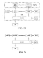
- FIG. 23 a new radio network architecture according to an example, not comprising all features being necessary for implementing the present invention is shown in FIG. 23 .
- the RAN is identical to that in FIG. 20 .
- Another way of functional decomposition for the functions of the PS domain of the CN in the present invention is to define functional units: an integrated GPRS support node server (IGSN-Server) and an integrated GPRS support node gateway (IGSN-GW).
- the IGSN-Server has control plane functions of both the original SGSN and GGSN.
- the IGSN-GW has user plane functions of both the original SGSN and GGSN.
- FIG. 24 A new radio network architecture according to an example, not comprising all features being necessary for implementing the present invention is shown in FIG. 24 .
- the RAN-Server and the IGSN-Server are integrated into one network element, which is referred to as a wireless-server (W-Server) and has control plane functions of the original RNC, SGSN, and GGSN.
- the RGW and the IGSN-GW are integrated into one network element, which is referred to as a wireless gateway (WGW) and has user plane functions of the original RNC, SGSN, and GGSN.
- An interface Iub-D between the network element BS and the WGW employs a user plane of an existing interface Iu originally configured between the RNC and the SGSN.
- a newly defined interface Iub-C is employed between the network element BS and the W-Server.
- An interface between the W-Server and the WGW employs Megaco of IETF or H.248 of ITU-T, or a completely new protocol stack.
- the W-Server manages the WGW via Megaco/H.248.
- a control plane of an existing interface Iur originally configured between the RNCs is employed between the W-Servers.
- a user plane of the existing interface Iur originally configured between the RNCs is employed between the WGWs.
- An additionally added interface between one BS and another BS employs the existing interface Iur originally configured between the RNCs.
- FIGs. 25 and 26 A first example, not comprising all features being necessary for implementing an interconnection between an optical access network (OAN) and a radio network according to a method of the present invention is shown in FIGs. 25 and 26 .
- a BS and WA of a 3G/2G radio communication network are interconnected with the OAN at a reference point (a) within the OAN via an AF.
- a RGW or a WRW of the 3G/2G radio communication network is interconnected with an OLT at a reference point v.
- the copper wire resources in the building are directly utilized when allocating 3G/2G radio communication network equipments in a building, and the 3G/2G radio communication network equipments access the OAN network via ONUs, thereby avoiding the additional wiring for the radio communication network and reducing the construction cost of the 3G/2G access network.
- the solution belongs to a tight-coupling solution.
- the BS and the WA are integrated into one network element.
- the integrated network element BS+WA and the AF may be separated as different network elements, and they are interconnected with each other at a reference point T.
- the network elements BS, WA, and AF are integrated into one network element.
- the network elements RGW and OLT may be integrated into one network element.
- the protocol stack under the path of UE->Node B->ONU->OLT->Core Network has a user plane as shown in FiGs. 27-29 , and a control plane as shown in FIGs. 30-32 .
- the functional decomposition of the BS, WA, and RAN-Server is shown in Table 1.
- the CN includes the SGSN and the GGSN.
- the SGSN and the GGSN may also be integrated into a new network element IGSN.
- the CN may also be implemented according to the solution shown in FIGs. 22 and 23 .
- the user equipment first establishes a radio resource control (RRC) connection via a control plane protocol stack and starts to establish a radio access bearer (RAB) after negotiating with the CN during the data communication.
- RRC radio resource control
- RAB radio access bearer
- RB user plane radio bearer
- the UE establishes an RRC connection with the UTRAN and then establishes a signaling connection with the CN via the RNC, which is also referred to as "NAS signaling establishment process" and suitable for exchanging the NAS information between signaling of the UE and that of the CN, for example, authentication, service request, and connection establishment.
- the application layer data of the UE is encapsulated into an IP packet or PPP packet and then transmitted to a PDCP protocol of an RNL.
- the PDCP protocol compresses the header of the data packet and delivers the compressed data to an RLC/MAC of the RNL.
- the RLC/MAC protocol adds an RLC/MAC header to the data packet after receiving and processing the data packet, and then transmits the data packet to an RFL layer of WCDMA.
- the RFL layer performs encoding, modulation, and other operations on the received data packet, and transmits the data packet to a UTRAN via an interface Uu.
- An RFL layer of WCDMA of the BS+WA in the UTRAN receives and transmits the data to a MAC/RLC protocol of the RNL.
- the MAC/RLC protocol removes the protocol headers sequentially, reassembles and combines the data, and then transmits the data to the PDCP protocol of the RNL.
- the PDCP protocol decompresses the compressed data packet header.
- the network element BS+WA forwards the decompressed data to the CN by using a GTP tunnel via an interface Iub-D and through the RGW.
- the GTP tunnel protocol, UDP, and IP of the interface Iu-D between the WA and the RGW may be directly carried on the OAN network.
- the OAN network between the WA and the RGW may employ a Layer 2 bridging technology (for example, Ethernet bridging). That is, the AF, ONU/ONT, and OLT are all Layer 2 network elements.
- a Layer 3 routing technology (for example, IP routing) is employed between the WA and the RGW. That is, the AF, ONU/ONT, and OLT are all Layer 3 network elements.
- the network element BS+WA divides the GTP/UDP/IP packet into LNK frames, then carries the LNK frames on the physical layer between the Node B and the AF, and then transmits them to the AF.
- the AF converts the LNK frames into ONU LNK frames, then carries the ONU LNK frames on the physical layer between the ONU/ONT and the AF, then transmits them to the ONU/ONT.
- the ONU/ONT converts the ONU/ONT LNK frames into ODN LNK frames suitable for optical transmission, then performs an electro-optical conversion to carry them on the ODN physical layer, and transmits them to the OLT via an optical fiber.
- the OLT PHY performs a photoelectric conversion to obtain the ODN LNK frames, then converts the ODN LNK frames into the LNK frames, and then transmits the LNK frames to the RGW for further processing.
- the RGW receives the data through the GTP tunnel via the interface Iub-D, performs processing on radio network layer and transport network layer of the interface Iu-D, and then transmits the data packet to a network element of the CN through the GTP tunnel.
- the SGSN/SGSN-GW receives the data through the GTP tunnel of the interface Iu-D, performs processing on transport network layer and radio network layer of the interface Iu-D, and then transmits the data to the GGSN/GGSN-GW via the interface Gn/Gn-D through the GTP tunnel.
- the data received by the GGSN/GGSN-GW through the GTP tunnel of the interface Gn/Gn-D is the IP packet or PPP packet from the UE.
- the GGSN/GGSN-GW transmits the data in the form of an IP packet or PPP protocol packet to an external network via an interface Gi.
- the IGSN/IGSN-GW performs the processing on transport network layer and radio network layer of the interface Iu-D.
- the data received through the GTP tunnel of the interface Iu-D is the IP packet or PPP packet from the UE.
- the IGSN/IGSN-GW transmits the data to the external network in the form of an IP packet or PPP protocol packet.
- the downlink is similar to the uplink, except that the PDCP protocol in the BS+WA is responsible for compressing the header of the downlink data, and the PDCP protocol in the UE is responsible for decompressing the header of the downlink data.
- the RRC of the UE encapsulates a GMM/SM/SMS message or a signaling message of the current layer into a data packet and transmits the data packet to the RLC/MAC of the RNL.
- the RLC/MAC protocol adds an RLC/MAC header to the data packet after receiving and processing the data packet, and then transmits the data packet to an RFL layer of WCDMA.
- the RFL layer performs encoding, modulation, and other operations on the received data packet, and transmits the data packet to a UTRAN via an interface Uu.
- An RFL layer of WCDMA of the BS+WA in the UTRAN receives and transmits the data to the MAC/RLC protocol of the RNL.
- the MAC/RLC protocol removes the protocol headers sequentially, reassembles and combines the data, and then transmits the data to the RRC protocol of the RNL.
- the RRC protocol directly resolves the signaling message and performs corresponding processing, such as connection establishment, and measurement report.
- the RRC of the BS+WA directly carries the corresponding signaling message via the radio network layer (for example, FP) and transport network layer (for example, IP/LNK/PHY) of the interface Iub-C, and informs the RRC layer of the RAN-Server about the processing result, and then forwards the signaling message to the CN through the RAN-Server via radio network layer (for example, NANAP) and transport network layer (for example, SCCP/M3UA/SCTP/IP/LNK/PHY, and M3UA/SCTP/IP is the signaling bearer layer in the figure) of the interface Iu-C.
- radio network layer for example, FP
- transport network layer for example, IP/LNK/PHY
- transport network layer for example, SCCP/M3UA/SCTP/IP/LNK/PHY
- M3UA/SCTP/IP is the signaling bearer layer in the figure
- the RRC, radio network layer (for example, FP or NBAP), and transport network layer (for example, IP layer or signaling bearer layer (for example, SCTP/IP)) of the interface Iub-C between the WA and the RAN-Server may be directly carried on the OAN network.
- the OAN network between the WA and the RAN-Server may employ a Layer 2 bridging technology (for example, Ethernet bridging). That is, the AF, ONU/ONT, and OLT are all Layer 2 network elements.
- a Layer 3 routing technology (for example, IP routing) is employed between the WA and the RAN-Server. That is, the AF, ONU/ONT, and OLT are all Layer 3 network elements.
- the network element BS+WA divides the FP/IP or NBAP/SCTP/IP packet of the interface Iub-C into LNK frames, then carries the LNK frames on the physical layer between the Node B and the AF, and then transmits them to the AF.
- the AF converts the LNK frames into ONU LNK frames, carries the ONU LNK frames on the physical layer between the ONU/ONT and the AF, and then transmits them to the ONU/ONT.
- the ONU/ONT converts the ONU/ONT LNK frames into ODN LNK frames suitable for optical transmission, then performs an electro-optical conversion to carry them on the ODN physical layer, and transmits them to the OLT via an optical fiber.
- the OLT PHY performs a photoelectric conversion to obtain the ODN LNK frames, converts the ODN LNK frames into the LNK frames, and transmits the LNK frames to the RAN-Server for further processing.
- the RAN-Server performs processing on transport network layer and radio network layer of the interface lub-C, obtains RNL frames of the RRC from the FP, and transmits the RNL frames to the MAC/RLC protocol of the RNL.
- the MAC/RLC protocol removes the protocol headers sequentially, reassembles and combines the data, and transmits the data to the RRC.
- the RRC protocol decompresses the compressed data packet header to obtain the data packet, and then transmits the data packet to a network element of the CN after performing the processing on radio network layer and transport network layer of the interface Iu-C.
- the IGSN/SGSN/IGSN-Server/SGSN-Server performs processing on transport network layer and radio network layer of the interface Iu-C and obtains the GMM/SM/SMS message from the RANAP.
- the UE receives a signaling message from the CN and an RRC signaling message from the access network through an opposite process.
- the RRC layer is respectively realized by the RAN-Server and the BS.
- the RRC directed to different functions of the RRC, fast connection establishment, fast feedback, resource allocation functions and the like are implemented in the BS; whereas data management, data storage, processing content of a plurality of BSs, and the like are implemented in the RAN-Server.
- a BS and a WA of a 3G/2G radio communication network are interconnected with an OAN broadband network at an ODN.
- An RGW or a WRW of the 3G/2G radio communication network is interconnected with an OLT at a reference point v.
- This solution belongs to a loose-coupling solution.
- the 3G/2G radio communication network directly utilizes the optical network resources of the OAN. For example, if an operator already has an FTTH network, WiMAX equipment is allocated in a building to directly access an ODN network.
- the network element BS+WA is integrated with functions of an ONU/ONT.
- the RGW or WGW may be integrated with the network element OLT into one network element.
- the protocol stack under the path of UE->Node B->ONU->OLT->Core Network has a user plane shown in FIG. 35 , and a control plane shown in FIG. 36 .
- the functional decomposition of the BS, WA, RAN-Server, and RGW is shown in Table 1.
- the CN includes the SGSN and the GGSN.
- the SGSN and the GGSN may also be integrated into a new network element IGSN.
- the CN may also be implemented according to the solution shown in FIGs. 22 and 23 .
- the application layer data of the UE is encapsulated into an IP packet or PPP packet and then transmitted to a PDCP protocol of an RNL.
- the PDCP protocol compresses the header of the data packet and transmits the compressed data to an RLC/MAC of the RNL.
- the RLC/MAC protocol adds an RLC/MAC header to the data packet after receiving and processing the data packet, and then transmits the data packet to an RFL layer of WCDMA.
- the RFL layer performs encoding, modulation, and other operations on the received data packet, and transmits the data packet to a UTRAN via an interface Uu.
- An RFL layer of WCDMA of the BS+WA+ONU/ONT in the UTRAN receives and transmits the data to a MAC/RLC protocol of the RNL.
- the MAC/RLC protocol removes the protocol headers sequentially, reassembles and combines the data, and then transmits the data to the PDCP protocol of the RNL.
- the PDCP protocol decompresses the compressed data packet header.
- the network element BS+WA+ONU/ONT forwards the decompressed data to the CN by using a GTP tunnel via an interface Iub-D and through the RGW.
- the GTP tunnel protocol, UDP, and IP of the interface Iu-D between the WA and the RGW may be directly carried on the OAN network.
- the OAN network between the WA and the RGW may employ a Layer 2 bridging technology (for example, Ethernet bridging). That is, the OLT is a Layer 2 network element.
- a Layer 3 routing technology for example, IP routing
- the OLT is a Layer 3 network element.
- the network element BS+WA+ONU/ONT divides the GTP/UDP/IP packet into ODN LNK frames suitable for optical transmission, then performs an electro-optical conversion to carry them on the ODN physical layer, and transmits them to the OLT via an optical fiber.
- the OLT PHY performs a photoelectric conversion to obtain the ODN LNK frames, converts the ODN LNK frames into the LNK frames, and then transmits the LNK frames to the RGW for further processing.
- the RGW receives the data through the GTP tunnel via the interface Iub-D, performs processing on radio network layer and transport network layer of the interface Iu-D, and then transmits the data packet to a network element of the CN through the GTP tunnel.
- the SGSN/SGSN-GW receives the data through the GTP tunnel of the interface Iu-D, performs processing on transport network layer and radio network layer of the interface Iu-D, and then transmits the data to the GGSN/GGSN-GW via the interface Gn/Gn-D through the GTP tunnel.
- the data received by the GGSN/GGSN-GW through the GTP tunnel of the interface Gn/Gn-D is the IP packet or PPP packet from the UE.
- the GGSN/GGSN-GW transmits the data in the form of an IP packet or PPP protocol packet to an external network via an interface Gi.
- the IGSN/IGSN-GW performs the processing on transport network layer and radio network layer of the interface Iu-D.
- the data received through the GTP tunnel of the interface Iu-D is the IP packet or PPP packet from the UE.
- the IGSN/IGSN-GW transmits the data to the external network in the form of an IP packet or PPP protocol packet.
- the downlink is similar to the uplink, except that the PDCP protocol in the BS+WA+ONU/ONT is responsible for compressing the header of the downlink data, and the PDCP protocol in the UE is responsible for decompressing the header of the downlink data.
- the RRC of the UE encapsulates a GMM/SM/SMS message or a signaling message of the current layer into a data packet, and transmits the data packet to the RLC/MAC of the RNL.
- the RLC/MAC protocol adds an RLC/MAC header to the data packet after receiving and processing the data packet, and then transmits the data packet to an RFL layer of WCDMA.
- the RFL layer performs encoding, modulation, and other operations on the received data packet and transmits the data packet to a UTRAN via an interface Uu.
- an RFL layer of WCDMA of the BS+WA+ONU/ONT in the UTRAN receives and transmits the data to a MAC/RLC protocol of the RNL.
- the MAC/RLC protocol removes the protocol headers sequentially, reassembles and combines the data, and then transmits the data to the RRC protocol of the RNL.
- the RRC protocol directly resolves the signaling message and performs corresponding processing, such as connection establishment and measurement report.
- the RRC of the BS+WA+ONU/ONT directly carries the corresponding signaling message via radio network layer (for example, FP) and transport network layer (for example, IP/LNK/PHY) of the interface Iub-C, and informs the RRC layer of the RAN-Server about the processing result, and then forwards the signaling message to the CN through the RAN-Server via the radio network layer (for example, NANAP) and transport network layer (for example, SCCP/M3UA/SCTP/IP/LNK/PHY, and M3UA/SCTP/IP is the signaling bearer layer in the figure) of the interface Iu-C.
- radio network layer for example, FP
- transport network layer for example, IP/LNK/PHY
- transport network layer for example, SCCP/M3UA/SCTP/IP/LNK/PHY
- M3UA/SCTP/IP is the signaling bearer layer in the figure
- the RRC, radio network layer (for example, FP or NBAP), and transport network layer (for example, IP layer or signaling bearer layer (for example, SCTP/IP)) of the interface lub-C between the WA and the RAN-Server may be directly carried on the OAN network.
- the OAN network between the WA and the RAN-Server may employ a Layer 2 bridging technology (for example, Ethernet bridging). That is, the OLT is a Layer 2 network element.
- a Layer 3 routing technology for example, IP routing
- the OLT is a Layer 3 network element.
- the network element BS+WA divides the FP/IP or NBAP/SCTP/IP packet of the interface Iub-C into ODN LNK frames suitable for optical transmission, then performs an electro-optical conversion to carry them on the ODN physical layer, and transmits them to the OLT via an optical fiber.
- the OLT PHY performs a photoelectric conversion to obtain the ODN LNK frames, converts the ODN LNK frames into the LNK frames, and transmits the LNK frames to the RAN-Server for further processing.
- the RAN-Server performs processing on transport network layer and radio network layer of the interface Iub-C, obtains RNL frames of the RRC from FP, and transmits the RNL frames to the MAC/RLC protocol of the RNL.
- the MAC/RLC protocol removes the protocol headers sequentially, reassembles and combines the data, and then transmits the data to the RRC.
- the RRC protocol decompresses the compressed data packet header to obtain the data packet, and then transmits the data packet to a network element of the CN after performing the processing on radio network layer and transport network layer of the interface Iu-C.
- the IGSN/SGSN/IGSN-Server/SGSN-Server performs the processing on transport network layer and radio network layer of the interface Iu-C and obtains the GMM/SM/SMS message from the RANAP.
- the UE receives a signaling message from the CN and a RRC signaling message from the access network through an opposite process.
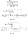
- FIG. 37 A flow chart of a processing method according to a specific example, not comprising all features being necessary for implementing the present invention is shown in FIG. 37 , which includes the following steps.
- Step 8-1 a radio interface protocol stack of a radio network is moved downward to a BS.
- the present invention provides a Wireless/Mobile over PON/DOCSIS-based radio network transmission solution.
- the core of the transmission solution lies in moving downward a radio interface protocol stack of a radio network to a BS.
- the radio network includes WCDMA, Global System for Mobile communications (GSM), General Packet Radio Service (GPRS), Time Division-Synchronous Code Division Multiple Access (TD-SCDMA), CDMA2000, enhanced 3G and the like.
- the existing functions of the BS in the radio network needs to be improved and a base station control processing unit needs to be configured in the BS, which are respectively described below.
- a radio network controller RNC
- BSC base station controller
- the RAN functions are re-decomposed.
- a portion of the RRC and PDCP/BMC/RLC/MAC functions of an RNL protocol stack in the radio interface protocol of the network are moved downward into the base station control processing unit configured in the BS.
- the new functions of the BS are shown in Table 3.
- the RAN functions in the network are re-decomposed.
- a base station controller unit included in the BS of the WiMAX implements a part of the functions of the ASN gateway, mainly including handover control, data path function, and radio resource management.
- the handover control function is directed to controlling the handover between user networks.
- the radio resource control and agent function is directed to the allocation and management of radio resources.
- the base station controller unit may be further integrated with other functions, for example, location register, service flow authentication and management, context function, robust header compression (ROHC), key management, paging control, DHCP relay, mobile IP foreign agent (MIP FA), proxy mobile IP client (PMIP Client), and authentication relay.
- the functions of the base station controller unit included in the BS of the WiMAX in the present invention are shown in Table 4.
- Step 8-2 the BS is connected to the PON/DOCSIS network, so as to realize that the BS transmits data through the PON or DOCSIS.
- the BSs are connected to the PON or DOCSIS network, so as to realize that the BSs transmit data through the PON or DOCSIS.
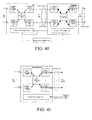
- FIG. 38 A schematic view for a BS to transmit data through employing a PON is shown in FIG. 38 .
- the BS is connected to an ODN of the PON network via an ONU/ONT.
- FIG. 39 A schematic view for a BS to transmit data through employing a DOCSIS is shown in FIG. 39 .
- the BS is connected to an HFC/Cable Network of the DOCSIS network via a CM.
- the transmission rate of the PON or DOCSIS is much higher than that of the E1/T1.
- the transmission rate of the PON is listed as follows.
- BPON has a transmission rate of 622 Mbps for downlink and 155 Mbps for uplink.
- EPON has a transmission rate of 1.25 Gbps symmetrically for uplink and downlink.
- GPON has a transmission rate of 1.25 Gbps/2.5 Gbps for downlink, and 155 Mbps/622 Mbps/1.25 Gbps/2.5 Gbps for uplink.
- the maximum transmission distance of the PON can reach as long as 20 Km.
- the transmission rate of the DOCSIS is shown in Table 5. Generally, the maximum transmission distance of the DOCSIS can reach as long as 5 Km. Table 5 Table of DOCSIS Transmission Rate DOCSIS Version 1 DOCSIS Version 2 DOCSIS Version 3 Downlink Bandwidth (Mbps/Channel) 40 40 200 Downlink Bandwidth (Gbps/Node) 5 5 6.3 Uplink Bandwidth (Mbps/Channel) 10 30 100 Uplink Bandwidth (Mbps/Node) 80 170 450
- the 3G/2G/WiMAX access network makes full use of the wire resources already allocated for the existing PON/DOCSIS network during construction, thereby reducing the construction cost of the 3G/2G/WiMAX access network.
- Systems for an interconnection between a BS and a wired network including two systems for the interconnection between the BS and the PON network and two systems for the interconnection between the BS and the DOCSIS network.
- FIG. 40 A structural diagram of a specific implementation of a system for an interconnection between a BS and a PON network according to an example, not comprising all features being necessary for implementing the present invention is shown in FIG. 40 , which includes the following modules: a BS equipment, an ONU/ONT equipment, and a remote power supply equipment.
- the BS equipment is connected to the ONU/ONT equipment at a reference point a via one or more pairs of wired cables, and adapted to accomplish radio access processing of a wireless subscriber, perform a base station control processing on data packets or frames of the accessed wireless subscriber and then deliver the processed data packets or frames to the ONU/ONT equipment, and perform the base station control processing on data packets or frames delivered from the ONU/ONT equipment and then output the processed data packets or frames to the wireless subscriber.
- the BS equipment may be a 3G/2G/802.16 BS.
- the BS equipment includes base station wireless physical layer processing units, a base station controller (BSC) processing unit, base station wired interface units, and a base station remote power supply unit.
- BSC base station controller
- the ONU/ONT equipment is connected to the BS equipment via one or more pairs of wired cables and connected to an OLT of an OAN via one or more pairs of optical cables, and adapted to convert data packets or frames delivered from the BS equipment into an optical transmission mode (for example, EPON or GPON format) and then deliver the data packets or frames in the optical transmission mode to the OLT of the OAN, and convert data packets or frames delivered from the OLT into an electrical transmission mode and then deliver the data packets or frames in the electrical transmission mode to the BS equipment.
- the ONU/ONT equipment includes ONU/ONT wired interface units, ONU/ONT optical transmission processing units, a switching unit, and an ONU/ONT remote power supply unit.
- the remote power supply equipment is adapted to convert a mains input (for example, 110V/220V AC) or a DC input (for example, -48V/-60V DC) into a high-voltage DC output (for example, 270V DC), so as to remotely supply power to both the ONU/ONT equipment and the BS equipment or to remotely supply power to the ONU/ONT equipment alone via wired cables (for example, one or more pairs of twisted pairs).
- the distance of the remote power supply is relevant to the core diameter, number of pairs for the wired cables, power consumption of the outdoor unit for the BS, and output voltage of the remote power supply equipment, and generally can reach a remote power supply distance of up to 2-5 Km.
- the remote power supply equipment may be integrated with the BS into one equipment.
- the base station wireless physical layer processing units in the BS equipment are adapted to accomplish an access of a wireless subscriber, deliver data packets or frames of the accessed wireless subscriber to the BSC processing unit, and deliver data packets or frames delivered from the BSC processing unit to the wireless subscriber.
- the units include one or more processing units, and each processing unit includes an antenna, a radio frequency (RF) processing module, an intermediate frequency processing module, and a base band processing module.
- RF radio frequency
- the BSC processing unit in the BS equipment is adapted to perform an uplink base station control processing on data packets or frames delivered from the base station wireless physical layer processing units and then deliver the processed data packets or frames to the wired interface units or transmit the processed data packets or frames back to the base station wireless physical layer processing units, and perform a downlink base station control processing on data packets or frames delivered from the wired interface units and then deliver the processed data packets or frames to the base station wireless physical layer processing units.
- This unit includes one or more processing units, and each processing unit is formed by a wireless data link layer processing module and a processing module of layers over the wireless data link layer.
- the BSC processing unit includes functions of RNC, BSC or BSC+PCF, or may include functions of the BSC of the BS shown in Table 1 or Table 2.
- the base station wired interface units in the BS equipment are connected to the ONU/ONT equipment via one or more pairs of wired cables, and adapted to perform a wired interface transmission processing on data packets or frames delivered from the BSC processing unit and then deliver the processed data packets or frames to the ONU/ONT equipment, and perform a wired interface receiving processing on data packets or frames delivered from the ONU/ONT equipment and then deliver the processed data packets or frames to the BSC processing unit.
- the units include one or more processing units. If the system supports a Layer 3 routing, the units support processing on IP layer, data link layer, and physical layer. If the system supports a Layer 2 bridging, the units support processing on data link layer and physical layer.
- the unit may be a base station Ethernet interface processing unit.
- the wired cables are Ethernet wired cables
- the data link layer is an Ethernet MAC layer
- the physical layer is an Ethernet PHY layer.
- the base station remote power supply unit in the BS equipment is adapted to convert a high-voltage DC (for example, 270V DC) from the remote power supply equipment or the remote power supply unit of the ONU/ONT equipment into a low-voltage DC, so as to locally supply power to the power supply unit of the BS equipment, or to relay the received high-voltage DC to remotely supply power to remote BS equipments in the next tier through wired cables.
- This unit also supports the intercommunication with the remote power supply equipment, so as to serve as an out-band management channel for the BS, thereby realizing surveillance alarm function during normal operations and system failures, which thus is convenient for equipment management, fault location, and remote maintenance.
- the wired interface units in the ONU/ONT equipment are connected to the BS equipment via one or more pairs of wired cables, and adapted to perform a wired interface receiving processing on data packets or frames delivered from the BS equipment and then deliver the processed data packets or frames to the optical transmission processing units, and perform a wired interface transmission processing on data packets or frames delivered from the optical transmission processing units and then deliver the processed data packets or frames to the BS equipment. If the system supports a Layer 3 routing, the units support processing on IP layer, data link layer, and physical layer. If the system supports a Layer 2 bridging, the units support processing on data link layer and physical layer.
- the unit may be an Ethernet interface processing unit.
- the wired cables are Ethernet wired cables
- the data link layer is an Ethernet MAC layer
- the physical layer is an Ethernet PHY layer.
- the optical transmission processing units in the ONU/ONT equipment are interconnected with the OLT of the OAN at the reference point (a) via one or more pairs of optical cables, and adapted to convert data packets or frames delivered from the wired interface units into an optical transmission mode (for example, EPON or GPON format) and then deliver the data packets or frames in the optical transmission mode to the OLT equipment, and convert data packets or frames delivered from the OLT into an electrical transmission mode and then deliver the data packets or frames in the electrical transmission mode to the wired interface units.
- the units include one or more optical transmission processing units.
- the switching unit in the ONU/ONT equipment is adapted to exchange data packets or frames between each wired interface unit and each optical transmission processing unit. If the system supports a Layer 3 routing, the unit is an IP switching unit. If the system supports a Layer 2 bridging, the unit is a Layer 2 switching unit. If only one optical transmission processing unit and one wired interface unit exist, the switching unit may be omitted.
- the remote power supply unit in the ONU/ONT equipment is adapted to convert a high-voltage DC (for example, 270V DC) from the remote power supply equipment into a low-voltage DC, so as to locally supply power to the power supply unit of the ONU/ONT equipment, or to relay the received high-voltage DC to remotely supply power to remote ONU/ONT equipments in the next tier through wired cables, which also remotely supplies power to BS equipments through wired cables.
- the unit further supports the intercommunication with the BS equipment or the remote power supply equipment, so as to serve as an out-band management channel for the ONU/ONT equipment, thereby realizing surveillance alarm function during normal operations and system failures, which thus is convenient for equipment management, fault location, and remote maintenance.
- FIG. 41 A structural diagram of a specific implementation of another system for an interconnection between a BS and a PON network according to the present invention is shown in FIG. 41 , which includes a BS equipment and a remote power supply equipment.
- the BS equipment is integrated with functions of an ONU/ONT and is connected to an ODN and an OLT equipment via one or more pairs of wired cables, and adapted to accomplish radio access processing of a wireless subscriber, perform a base station control processing on data packets or frames of the accessed wireless subscriber and then deliver the processed data packets and frames to the OLT equipment, and perform the base station control processing on data packets or frames delivered from the OLT equipment and then output the processed data packets or frames to the wireless subscriber.
- the BS equipment may be a 3G/2G/802.16 BS.
- the BS equipment includes base station wireless physical layer processing units, a BSC processing unit, optical transmission processing units, and a base station remote power supply unit.
- the remote power supply equipment is adapted to convert a mains input (for example, 110V/220V AC) or a DC input (for example, -48V/-60V DC) into a high-voltage DC (for example, 270V DC), so as to remotely supply power to the BS equipment through wired cables (for example, one or more pairs of twisted pairs).
- the distance of the remote power supply is relevant to the core diameter, number of pairs for the wired cables, power consumption of the outdoor unit for the BS, and output voltage of the remote power supply equipment, and generally reaches a remote power supply distance of up to 2-5 Km.
- the remote power supply equipment may be integrated with the BS into one equipment.
- the base station wireless physical layer processing units in the BS equipment are adapted to accomplish an access of a wireless subscriber, deliver data packets or frames of the accessed wireless subscriber to the BSC processing unit, and deliver data packets or frames delivered from the BSC processing unit to the wireless subscriber.
- the units include one or more processing units, and each processing unit includes an antenna, an RF processing module, an intermediate frequency processing module, and a base band processing module.
- the BSC processing unit in the BS equipment is adapted to perform an uplink base station control processing on data packets or frames delivered from the base station wireless physical layer processing units and then deliver the processed data packets or frames delivered to the optical transmission processing units or transmit the processed data packets or frames back to the base station wireless physical layer processing units, and perform a downlink base station control processing on data packets or frames delivered from the optical transmission processing units and then deliver the processed data packets or frames to the base station wireless physical layer processing units.
- the unit includes one or more processing units, and each processing unit is formed by a wireless data link layer processing module and a processing module of layers over the wireless data link layer.
- the BSC processing unit may include functions of RNC, BSC, or BSC+PCF, or may include functions of the BSC of the BS shown in Table 1 or Table 2.
- the optical transmission processing units in the BS equipment are interconnected with the OLT through the ODN via one or more pairs of optical cables, and adapted to convert data packets or frames delivered from the BSC processing unit into an optical transmission mode (for example, EPON or GPON format) and then deliver the data packets or frames in the optical transmission mode to the OLT, and convert data packets or frames delivered from the OLT into an electrical transmission mode and then deliver the data packets or frames in the electrical transmission mode to the BSC processing unit.
- the units include one or more optical transmission processing units.
- the base station remote power supply unit in the BS equipment is adapted to convert a high-voltage DC (for example, 270V DC) from the remote power supply equipment into a low-voltage DC, so as to locally supply power to the power supply unit of the BS equipment, or to relay the received high-voltage DC to remotely supply power to remote base station equipments at the next tier through wired cables.
- the unit further supports the intercommunication with the remote power supply equipment, so as to serve as an out-band management channel for the BS equipment, thereby realizing surveillance alarm function during normal operations and system failures, which thus is convenient for equipment management, fault location, and remote maintenance.
Landscapes
- Engineering & Computer Science (AREA)
- Computer Networks & Wireless Communication (AREA)
- Signal Processing (AREA)
- Mobile Radio Communication Systems (AREA)
Claims (28)
- Système pour optimiser une couche de réseau radio pour mettre en oeuvre une interconnexion de réseau comprenant un serveur sans fil (W-Server) et un appareil station de base plus adaptateur sans fil, BS+WA ;
le serveur sans fil, conçu pour comprendre des fonctions de plan de contrôle de noeud de support GPRS de desserte (SGSN), des fonctions de plan de contrôle de noeud de support GPRS de passerelle (GGSN) et une partie des fonctions de plan de contrôle de contrôleur de réseau radio (RNC), où la partie des fonctions de plan de contrôle de RNC comprend la fonction de distribution par diffusion et la fonction de contrôle de repositionnement, et
l'élément de réseau BS+WA, conçu pour parachever le traitement du contrôle d'accès au support, MAC, du contrôle de liaison radio, RLC, du protocole de convergence de données en paquets, PDCP, et une partie du contrôle des ressources radio, RRC, où la partie des RRC comprend la fonction de gestion des ressources radio spécifiques à la cellule, CS-RRM, et la fonction de contrôle de transfert, contrôle HO ;
caractérisé en ce que
l'appareil BS+WA et le serveur W-Server sont interconnectés par une interface Iub-C et l'interface Iub-C comprend une partie d'application de noeud B, NBAP. - Système selon la revendication 1, dans lequel :l'appareil BS+WA est en outre conçu pour communiquer avec une passerelle de noeud de support GPRS intégré, IGSN-GW ; etoù l'IGSN-GW a des fonctions de plan d'utilisateur du SGSN et du GGSN.
- Système selon la revendication 2, dans lequel :l'appareil BS+WA est en outre conçu pour s'interconnecter avec un réseau d'accès optique, OAN, d'un réseau optique passif, PON, en un point de référence « a » dans l'OAN via une fonction d'adaptation, AF.
- Système selon la revendication 3, dans lequel :l'appareil BS+WA est conçu pour s'interconnecter avec l'AF en un point de référence « T » ; oudans lequel l'appareil BS+WA comprend en outre l'AF.
- Système selon la revendication 2, dans lequel :l'appareil BS+WA est interconnecté avec le réseau large bande OAN au niveau d'un réseau de distribution optique, ODN.
- Système selon la revendication 5, dans lequel :l'appareil BS+WA est intégré avec des fonctions d'une unité de réseau optique/d'un terminal de réseau optique, ONU/ONT.
- Système selon la revendication 1, dans lequel :l'appareil BS+WA est en outre conçu pour communiquer avec une passerelle sans fil, WGW, et ;dans lequella WGW a des fonctions de plan d'utilisateur du RNC, du SGSN et du GGSN.
- Système selon la revendication 7, dans lequel :l'appareil BS+WA est interconnecté avec un OAN en un point de référence « a » dans l'OAN d'un PON via une AF ;etla WGW est interconnectée avec un terminal de ligne optique, OLT, en un point de référence « v ».
- Système selon la revendication 8, dans lequel :l'appareil BS+WA et l'AF sont interconnectés avec l'AF en un point de référence «T»;oudans lequel l'appareil BS+WA comprend en outre l'AF.
- Système selon la revendication 7, dans lequel :l'appareil BS+WA est interconnecté avec le réseau large bande OAN au niveau d'un ODN;etla WGW est interconnectée avec un OLT en un point de référence « v ».
- Système selon la revendication 10, dans lequel :l'appareil BS+WA est intégré avec des fonctions d'un ONU/ONT ;oula WGW est intégrée avec l'OLT dans un élément de réseau.
- Système selon l'une quelconque des revendications précédentes, dans lequel l'appareil BS+WA est en outre conçu pour supporter un tunnel GTP.
- Système selon l'une quelconque des revendications précédentes, dans lequel l'appareil BS+WA est en outre conçu pour supporter SCTP/IP.
- Système selon la revendication 1, comprenant en outre une passerelle sans fil, WGW, où la WGW est conçue pour avoir des fonctions de plan d'utilisateur du SGSN et du GGSN.
- Système selon la revendication 14, dans lequel la WGW est en outre conçue pour avoir des fonctions de plan d'utilisateur du RNC.
- Appareil station de base plus adaptateur sans fil, BS+WA, pour optimiser une couche de réseau radio pour mettre en oeuvre une interconnexion de réseau comprenant un moyen conçu pour parachever le traitement du contrôle d'accès au support, MAC, du contrôle de liaison radio, RLC, du protocole de convergence de données en paquets, PDCP, et une partie du contrôle des ressources radio, RRC, où la partie des RRC comprend la fonction de gestion des ressources radio spécifiques à la cellule, CS-RRM, et la fonction de contrôle de transfert, contrôle HO, caractérisé en ce que l'appareil BS+WA est en outre conçu pour s'interconnecter avec un serveur sans fil, W-Server, par une interface Iub-C, et l'interface Iub-C comprend une partie d'application de noeud B, NBAP.
- Appareil selon la revendication 16, dans lequel :l'appareil est en outre conçu pour communiquer avec une passerelle de noeud de support GPRS intégré, IGSN-GW ; etoù l'IGSN-GW a des fonctions de plan d'utilisateur du SGSN et du GGSN.
- Appareil selon la revendication 17, dans lequel :l'appareil est en outre conçu pour s'interconnecter avec un réseau d'accès optique, OAN, d'un réseau optique passif, PON, en un point de référence « a » dans l'OAN via une fonction d'adaptation, AF.
- Appareil selon la revendication 18, dans lequel :l'appareil est conçu pour s'interconnecter avec l'AF en un point de référence « T » ;oudans lequel l'appareil comprend en outre l'AF.
- Appareil selon la revendication 17, dans lequel :l'appareil est interconnecté avec le réseau large bande OAN au niveau d'un réseau de distribution optique, ODN.
- Appareil selon la revendication 20, dans lequel :l'appareil est intégré avec des fonctions d'une unité de réseau optique/d'un terminal de réseau optique, ONU/ONT.
- Appareil selon la revendication 16, dans lequel :l'appareil est en outre conçu pour communiquer avec une passerelle sans fil, WGW,et ;dans lequella WGW a des fonctions de plan d'utilisateur du RNC, du SGSN et du GGSN.
- Appareil selon la revendication 22, dans lequel :l'appareil est interconnecté avec un OAN en un point de référence « a » dans l'OAN d'un PON via une AF ;etla WGW est interconnectée avec un terminal de ligne optique, OLT, en un point de référence « v ».
- Appareil selon la revendication 23, dans lequel :l'appareil et l'AF sont interconnectés avec l'AF en un point de référence « T » ;oudans lequel l'appareil comprend en outre l'AF.
- Appareil selon la revendication 22, dans lequel :l'appareil est interconnecté avec le réseau large bande OAN au niveau d'un ODN ;etla WGW est interconnectée avec un OLT en un point de référence « v ».
- Appareil selon la revendication 25, dans lequel :l'appareil est intégré avec des fonctions d'un ONU/ONT ;oula WGW est intégrée avec l'OLT dans un élément de réseau.
- Appareil selon l'une quelconque des revendications précédentes, dans lequel l'appareil est en outre conçu pour supporter un tunnel GTP.
- Appareil selon l'une quelconque des revendications précédentes, dans lequel l'appareil est en outre conçu pour supporter SCTP/IP.
Applications Claiming Priority (4)
| Application Number | Priority Date | Filing Date | Title |
|---|---|---|---|
| CN2006100326139A CN1996914B (zh) | 2005-12-31 | 2005-12-31 | 一种无线网络层下移实现网络互连的系统及方法 |
| CN2006100326143A CN1996915B (zh) | 2005-12-31 | 2005-12-31 | 一种无线网络层下移实现网络互连的系统和方法 |
| CNA2006100016221A CN101005321A (zh) | 2006-01-18 | 2006-01-18 | 基站和有线网络互连的方法和系统 |
| EP06840756A EP1971083A4 (fr) | 2005-12-31 | 2006-12-30 | Procede et systeme d'optimisation de la couche reseau radio en vue de l'interconnexion entre reseaux et procede d'interconnexion entre le reseau radio et le reseau cable |
Related Parent Applications (2)
| Application Number | Title | Priority Date | Filing Date |
|---|---|---|---|
| EP06840756A Division EP1971083A4 (fr) | 2005-12-31 | 2006-12-30 | Procede et systeme d'optimisation de la couche reseau radio en vue de l'interconnexion entre reseaux et procede d'interconnexion entre le reseau radio et le reseau cable |
| EP06840756.8 Division | 2006-12-30 |
Publications (3)
| Publication Number | Publication Date |
|---|---|
| EP2309679A2 EP2309679A2 (fr) | 2011-04-13 |
| EP2309679A3 EP2309679A3 (fr) | 2011-06-08 |
| EP2309679B1 true EP2309679B1 (fr) | 2014-05-07 |
Family
ID=38227914
Family Applications (3)
| Application Number | Title | Priority Date | Filing Date |
|---|---|---|---|
| EP11153330.3A Not-in-force EP2309679B1 (fr) | 2005-12-31 | 2006-12-30 | Procédé et système d'optimisation de la couche réseau radio en vue de l'interconnexion entre réseaux et procédé d'interconnexion entre le réseau radio et le réseau cable |
| EP06840756A Withdrawn EP1971083A4 (fr) | 2005-12-31 | 2006-12-30 | Procede et systeme d'optimisation de la couche reseau radio en vue de l'interconnexion entre reseaux et procede d'interconnexion entre le reseau radio et le reseau cable |
| EP20100173687 Not-in-force EP2247038B1 (fr) | 2005-12-31 | 2006-12-30 | Procédé et système d'optimisation de la couche réseau radio en vue de l'interconnexion entre réseaux et procédé d'interconnexion entre le réseau radio et le réseau cable |
Family Applications After (2)
| Application Number | Title | Priority Date | Filing Date |
|---|---|---|---|
| EP06840756A Withdrawn EP1971083A4 (fr) | 2005-12-31 | 2006-12-30 | Procede et systeme d'optimisation de la couche reseau radio en vue de l'interconnexion entre reseaux et procede d'interconnexion entre le reseau radio et le reseau cable |
| EP20100173687 Not-in-force EP2247038B1 (fr) | 2005-12-31 | 2006-12-30 | Procédé et système d'optimisation de la couche réseau radio en vue de l'interconnexion entre réseaux et procédé d'interconnexion entre le réseau radio et le réseau cable |
Country Status (3)
| Country | Link |
|---|---|
| US (1) | US8660430B2 (fr) |
| EP (3) | EP2309679B1 (fr) |
| WO (1) | WO2007076713A1 (fr) |
Families Citing this family (48)
| Publication number | Priority date | Publication date | Assignee | Title |
|---|---|---|---|---|
| CN100525236C (zh) * | 2005-12-19 | 2009-08-05 | 华为技术有限公司 | 光网络与无线通信网络互连的系统及其通信方法 |
| US8160447B2 (en) * | 2007-10-17 | 2012-04-17 | Hitachi, Ltd. | Communication system using passive optical network and passive optical network |
| US8160448B2 (en) * | 2007-10-17 | 2012-04-17 | Hitachi, Ltd. | Communication system using passive optical network and passive optical network |
| JP5088091B2 (ja) * | 2007-10-29 | 2012-12-05 | 富士通株式会社 | 基地局装置、通信方法及び移動通信システム |
| EP2344915A4 (fr) | 2008-10-09 | 2015-01-21 | Corning Cable Sys Llc | Terminal à fibre optique ayant un panneau adaptateur portant à la fois les fibres d'entrée et de sortie provenant d'un diviseur optique |
| US9673904B2 (en) | 2009-02-03 | 2017-06-06 | Corning Optical Communications LLC | Optical fiber-based distributed antenna systems, components, and related methods for calibration thereof |
| WO2010090999A1 (fr) | 2009-02-03 | 2010-08-12 | Corning Cable Systems Llc | Systèmes d'antennes réparties basés sur les fibres optiques, composants et procédés associés destinés à leur surveillance et à leur configuration |
| FR2945397B1 (fr) * | 2009-05-06 | 2011-05-06 | St Ericsson Sa St Ericsson Ltd | Procede de traitement de paquets du type ip destines a etre vehicules sur un canal de communication d'un reseau sans fil, et equipement correspondant |
| US8213800B1 (en) * | 2009-07-17 | 2012-07-03 | Tellabs Operations, Inc. | Wireless backhaul communication using passive optical network |
| WO2011045527A2 (fr) * | 2009-10-13 | 2011-04-21 | France Telecom | Procede de rattachement d'un terminal mobile a un reseau optique fixe |
| US8280259B2 (en) | 2009-11-13 | 2012-10-02 | Corning Cable Systems Llc | Radio-over-fiber (RoF) system for protocol-independent wired and/or wireless communication |
| US8275265B2 (en) | 2010-02-15 | 2012-09-25 | Corning Cable Systems Llc | Dynamic cell bonding (DCB) for radio-over-fiber (RoF)-based networks and communication systems and related methods |
| CN102196524A (zh) * | 2010-03-09 | 2011-09-21 | 中兴通讯股份有限公司 | 服务无线网络控制器识别传输承载能力的方法及系统 |
| US9252874B2 (en) | 2010-10-13 | 2016-02-02 | Ccs Technology, Inc | Power management for remote antenna units in distributed antenna systems |
| US9720197B2 (en) | 2010-10-19 | 2017-08-01 | Corning Optical Communications LLC | Transition box for multiple dwelling unit fiber optic distribution network |
| KR101472100B1 (ko) * | 2010-12-22 | 2014-12-11 | 주식회사 케이티 | 무선통신 시스템에서 기지국 장비 및 데이터 처리 방법 |
| WO2012148940A1 (fr) | 2011-04-29 | 2012-11-01 | Corning Cable Systems Llc | Systèmes, procédés et dispositifs pour augmenter la puissance radiofréquence (rf) dans systèmes d'antennes distribuées |
| WO2012148938A1 (fr) | 2011-04-29 | 2012-11-01 | Corning Cable Systems Llc | Détermination de temps de propagation de communications dans systèmes d'antennes distribuées, et composants, systèmes et procédés associés |
| US8762501B2 (en) * | 2011-08-29 | 2014-06-24 | Telefonaktiebolaget L M Ericsson (Publ) | Implementing a 3G packet core in a cloud computer with openflow data and control planes |
| US9219546B2 (en) | 2011-12-12 | 2015-12-22 | Corning Optical Communications LLC | Extremely high frequency (EHF) distributed antenna systems, and related components and methods |
| US10110307B2 (en) | 2012-03-02 | 2018-10-23 | Corning Optical Communications LLC | Optical network units (ONUs) for high bandwidth connectivity, and related components and methods |
| WO2013162988A1 (fr) | 2012-04-25 | 2013-10-31 | Corning Cable Systems Llc | Architectures de système d'antenne distribué |
| WO2014022966A1 (fr) * | 2012-08-07 | 2014-02-13 | 华为技术有限公司 | Système d'accès, et procédé et dispositif de communication d'un réseau à fibre optique |
| US9455784B2 (en) | 2012-10-31 | 2016-09-27 | Corning Optical Communications Wireless Ltd | Deployable wireless infrastructures and methods of deploying wireless infrastructures |
| CN103973645B (zh) * | 2013-01-30 | 2017-11-24 | 华为技术有限公司 | 一种数据传输方法和相关装置 |
| US9557505B2 (en) | 2013-03-18 | 2017-01-31 | Commscope Technologies Llc | Power and optical fiber interface |
| AU2014275486B2 (en) * | 2013-03-18 | 2017-07-27 | Commscope Technologies Llc | Architecture for a wireless network |
| CN103297166B (zh) * | 2013-04-28 | 2015-05-27 | 烽火通信科技股份有限公司 | 基于wdm-pon的移固综合接入系统及方法 |
| CN103701640B (zh) * | 2013-12-18 | 2016-09-28 | 烽火通信科技股份有限公司 | 使用智能管理终端升级odn设备的方法及系统 |
| CN105024755B (zh) * | 2014-04-21 | 2018-02-27 | 江苏艾思特信息科技有限公司 | 移动回程光纤通信网络 |
| US9357551B2 (en) | 2014-05-30 | 2016-05-31 | Corning Optical Communications Wireless Ltd | Systems and methods for simultaneous sampling of serial digital data streams from multiple analog-to-digital converters (ADCS), including in distributed antenna systems |
| US9681313B2 (en) | 2015-04-15 | 2017-06-13 | Corning Optical Communications Wireless Ltd | Optimizing remote antenna unit performance using an alternative data channel |
| US9948349B2 (en) | 2015-07-17 | 2018-04-17 | Corning Optical Communications Wireless Ltd | IOT automation and data collection system |
| EP3354114B1 (fr) | 2015-09-21 | 2019-11-06 | Telefonaktiebolaget LM Ericsson (publ) | Procédé et appareil pour un noeud radio et une passerelle à fonctions radio |
| US10356496B2 (en) * | 2016-01-27 | 2019-07-16 | Accelink Technologies Co., Ltd. | Converged passive optical LAN |
| US10492104B2 (en) | 2016-03-10 | 2019-11-26 | Cable Television Laboratories, Inc. | Latency reduction in wireless service |
| CN109076413B (zh) * | 2016-03-10 | 2021-09-28 | 有线电视实验室公司 | 用于等待时间减少的系统和方法 |
| US10420085B2 (en) | 2016-10-07 | 2019-09-17 | Cable Television Laboratories, Inc. | System and method for grant assignment |
| US12225536B2 (en) | 2016-10-07 | 2025-02-11 | Cable Television Laboratories, Inc. | System and method for grant assignment |
| EP3539255A4 (fr) | 2016-11-09 | 2020-05-27 | Commscope Inc. of North Carolina | Module d'infrastructure alimenté échangeable |
| US10735838B2 (en) | 2016-11-14 | 2020-08-04 | Corning Optical Communications LLC | Transparent wireless bridges for optical fiber-wireless networks and related methods and systems |
| CN109982337A (zh) * | 2019-03-12 | 2019-07-05 | 巢湖学院 | 一种移动通信系统的配置传输方法 |
| US11265834B2 (en) * | 2019-10-10 | 2022-03-01 | Acer Incorporated | Base stations and methods for time-sensitive networking (TSN) clock information delivery |
| US11381278B1 (en) | 2019-12-11 | 2022-07-05 | Cable Television Laboratories, ino. | Systems and methods for extending wireline communication networks |
| WO2022025315A1 (fr) * | 2020-07-29 | 2022-02-03 | 엘지전자 주식회사 | Dispositif de commande de phase pour balayage de faisceau continu dans une portée de balayage efficace et procédé associé |
| US11576117B1 (en) | 2021-07-23 | 2023-02-07 | Charter Communications Operating, Llc | Methods and apparatus for cable network power management |
| US12003816B2 (en) * | 2021-07-23 | 2024-06-04 | Charter Communications Operating, Llc | Methods and apparatus for dynamic cable network power management |
| US12283992B2 (en) * | 2022-11-14 | 2025-04-22 | At&T Intellectual Property I, L.P. | Enhanced fiber broadband connection deployment method and system |
Family Cites Families (19)
| Publication number | Priority date | Publication date | Assignee | Title |
|---|---|---|---|---|
| US5734979A (en) * | 1995-05-04 | 1998-03-31 | Interwave Communications International, Ltd. | Cellular base station with intelligent call routing |
| GB9805765D0 (en) * | 1997-06-10 | 1998-05-13 | Northern Telecom Ltd | Data transmission over a power line communications system |
| US6473608B1 (en) * | 1999-01-12 | 2002-10-29 | Powerdsine Ltd. | Structure cabling system |
| US6804256B2 (en) * | 2001-07-24 | 2004-10-12 | Glory Telecommunications Co., Ltd. | Automatic bandwidth adjustment in a passive optical network |
| US20030032451A1 (en) * | 2001-08-10 | 2003-02-13 | Jianhong Hu | Architecture for converged broadband wireless communications |
| US7305704B2 (en) * | 2002-03-16 | 2007-12-04 | Trustedflow Systems, Inc. | Management of trusted flow system |
| CN1219371C (zh) | 2002-04-30 | 2005-09-14 | 华为技术有限公司 | 一种适用于高速分组数据传输的无线接入网 |
| CA2501991C (fr) | 2002-10-18 | 2010-09-14 | Kineto Wireless, Inc. | Dispositif et procede pour l'extension de la zone de couverture d'un systeme de communications hertziennes agree, au moyen d'un systeme de communications hertziennes non agree |
| US7634269B2 (en) | 2002-10-18 | 2009-12-15 | Kineto Wireless, Inc. | Apparatus and method for extending the coverage area of a licensed wireless communication system using an unlicensed wireless communication system |
| US7562393B2 (en) * | 2002-10-21 | 2009-07-14 | Alcatel-Lucent Usa Inc. | Mobility access gateway |
| KR100965670B1 (ko) * | 2002-12-10 | 2010-06-24 | 삼성전자주식회사 | 이동통신시스템의 시스템간 셀 변경 방법 |
| US7450520B2 (en) | 2003-02-14 | 2008-11-11 | Nortel Networks Limited | Remote interface for a network device in the physical plant |
| KR20040077250A (ko) | 2003-02-28 | 2004-09-04 | 주식회사 케이티 | 수동광통신망 시스템 및 그의 채널 할당방법 |
| GB2410861B (en) * | 2004-02-04 | 2006-03-22 | Nec Technologies | An apparatus for network communication in a multi-radio access technology system |
| US7634024B2 (en) * | 2005-01-31 | 2009-12-15 | Agere Systems Inc. | Adaptive peak windowing for crest factor reduction in a communication system transmitter |
| EP1956762B1 (fr) * | 2005-12-03 | 2014-08-27 | Huawei Technologies Co., Ltd. | Systeme et procede de mise en oeuvre d'interconnexion entre reseau dsl et reseau radio |
| CN100525236C (zh) * | 2005-12-19 | 2009-08-05 | 华为技术有限公司 | 光网络与无线通信网络互连的系统及其通信方法 |
| CN1996914B (zh) | 2005-12-31 | 2010-12-08 | 华为技术有限公司 | 一种无线网络层下移实现网络互连的系统及方法 |
| CN101005321A (zh) | 2006-01-18 | 2007-07-25 | 华为技术有限公司 | 基站和有线网络互连的方法和系统 |
-
2006
- 2006-12-30 EP EP11153330.3A patent/EP2309679B1/fr not_active Not-in-force
- 2006-12-30 WO PCT/CN2006/003726 patent/WO2007076713A1/fr not_active Ceased
- 2006-12-30 EP EP06840756A patent/EP1971083A4/fr not_active Withdrawn
- 2006-12-30 EP EP20100173687 patent/EP2247038B1/fr not_active Not-in-force
-
2008
- 2008-06-27 US US12/163,223 patent/US8660430B2/en not_active Expired - Fee Related
Non-Patent Citations (1)
| Title |
|---|
| ERIK WEIS: "IP based access technologies and QoS", INTERNET CITATION, 1 May 2003 (2003-05-01), pages 1 - 144, XP002538175, Retrieved from the Internet <URL:http://www.eurescom.de/~pub/deliverables/documents/P1100-series/P1117 /D1/p1117-d1.pdf> [retrieved on 20090721] * |
Also Published As
| Publication number | Publication date |
|---|---|
| WO2007076713A1 (fr) | 2007-07-12 |
| EP2247038B1 (fr) | 2015-04-22 |
| EP1971083A1 (fr) | 2008-09-17 |
| EP1971083A4 (fr) | 2009-11-04 |
| EP2247038A1 (fr) | 2010-11-03 |
| US8660430B2 (en) | 2014-02-25 |
| US20080260389A1 (en) | 2008-10-23 |
| EP2309679A3 (fr) | 2011-06-08 |
| EP2309679A2 (fr) | 2011-04-13 |
Similar Documents
| Publication | Publication Date | Title |
|---|---|---|
| EP2309679B1 (fr) | Procédé et système d'optimisation de la couche réseau radio en vue de l'interconnexion entre réseaux et procédé d'interconnexion entre le réseau radio et le réseau cable | |
| CN100525236C (zh) | 光网络与无线通信网络互连的系统及其通信方法 | |
| US20090003831A1 (en) | Network Interconnection System And Method With Separated Controlling And Bearing | |
| US8027321B2 (en) | Method and system for interconnecting digital subscriber line network and radio communication network | |
| CN101374266A (zh) | 数据发送、接收方法及无线接入点设备、网关、通信系统 | |
| US8144646B2 (en) | Method and system for interconnecting broadband wireless access network with optical access broadband network | |
| CN101309442B (zh) | 无线通信设备及数据传输方法 | |
| CN101005321A (zh) | 基站和有线网络互连的方法和系统 | |
| CN1996915B (zh) | 一种无线网络层下移实现网络互连的系统和方法 | |
| CN102158992B (zh) | 基站和有线网络互连的方法和系统 | |
| WO2012065419A1 (fr) | Procédé, système et sous-système logique de traitement en cascade pour mettre en oeuvre une mise en cascade de stations de base | |
| CN1996914B (zh) | 一种无线网络层下移实现网络互连的系统及方法 | |
| CN101061678B (zh) | 优化无线网络层实现网络互连的方法和系统及无线网络与有线网络的互连方法 | |
| Ayanoglu et al. | Mobile information infrastructure | |
| KR20060040672A (ko) | 유니버설 이동 전화 시스템 네트워크를 위한 오버레이마이크로 셀 구조 | |
| CN101156383B (zh) | 实现数字用户线网络与无线通信网络互连的方法及系统 | |
| KR19990016603A (ko) | 개인 휴대 통신망 | |
| KR100565706B1 (ko) | 이동통신패킷데이터네트워크 | |
| HK1155871A (en) | Method and system for realizing base station cascading and cascading processing logic subsystem |
Legal Events
| Date | Code | Title | Description |
|---|---|---|---|
| PUAI | Public reference made under article 153(3) epc to a published international application that has entered the european phase |
Free format text: ORIGINAL CODE: 0009012 |
|
| 17P | Request for examination filed |
Effective date: 20110204 |
|
| AC | Divisional application: reference to earlier application |
Ref document number: 1971083 Country of ref document: EP Kind code of ref document: P |
|
| AK | Designated contracting states |
Kind code of ref document: A2 Designated state(s): AT BE BG CH CY CZ DE DK EE ES FI FR GB GR HU IE IS IT LI LT LU LV MC NL PL PT RO SE SI SK TR |
|
| AX | Request for extension of the european patent |
Extension state: AL BA HR MK RS |
|
| PUAL | Search report despatched |
Free format text: ORIGINAL CODE: 0009013 |
|
| AK | Designated contracting states |
Kind code of ref document: A3 Designated state(s): AT BE BG CH CY CZ DE DK EE ES FI FR GB GR HU IE IS IT LI LT LU LV MC NL PL PT RO SE SI SK TR |
|
| AX | Request for extension of the european patent |
Extension state: AL BA HR MK RS |
|
| 17Q | First examination report despatched |
Effective date: 20111219 |
|
| REG | Reference to a national code |
Ref country code: DE Ref legal event code: R079 Ref document number: 602006041547 Country of ref document: DE Free format text: PREVIOUS MAIN CLASS: H04L0012460000 Ipc: H04W0088120000 |
|
| RIC1 | Information provided on ipc code assigned before grant |
Ipc: H04W 92/14 20090101ALN20130605BHEP Ipc: H04W 88/12 20090101AFI20130605BHEP |
|
| GRAP | Despatch of communication of intention to grant a patent |
Free format text: ORIGINAL CODE: EPIDOSNIGR1 |
|
| INTG | Intention to grant announced |
Effective date: 20131121 |
|
| RIN1 | Information on inventor provided before grant (corrected) |
Inventor name: ZHENG, RUOBIN |
|
| GRAS | Grant fee paid |
Free format text: ORIGINAL CODE: EPIDOSNIGR3 |
|
| GRAA | (expected) grant |
Free format text: ORIGINAL CODE: 0009210 |
|
| AC | Divisional application: reference to earlier application |
Ref document number: 1971083 Country of ref document: EP Kind code of ref document: P |
|
| AK | Designated contracting states |
Kind code of ref document: B1 Designated state(s): AT BE BG CH CY CZ DE DK EE ES FI FR GB GR HU IE IS IT LI LT LU LV MC NL PL PT RO SE SI SK TR |
|
| REG | Reference to a national code |
Ref country code: GB Ref legal event code: FG4D |
|
| REG | Reference to a national code |
Ref country code: AT Ref legal event code: REF Ref document number: 667500 Country of ref document: AT Kind code of ref document: T Effective date: 20140515 |
|
| REG | Reference to a national code |
Ref country code: IE Ref legal event code: FG4D |
|
| REG | Reference to a national code |
Ref country code: DE Ref legal event code: R096 Ref document number: 602006041547 Country of ref document: DE Effective date: 20140618 |
|
| REG | Reference to a national code |
Ref country code: NL Ref legal event code: T3 |
|
| REG | Reference to a national code |
Ref country code: AT Ref legal event code: MK05 Ref document number: 667500 Country of ref document: AT Kind code of ref document: T Effective date: 20140507 |
|
| REG | Reference to a national code |
Ref country code: LT Ref legal event code: MG4D |
|
| PG25 | Lapsed in a contracting state [announced via postgrant information from national office to epo] |
Ref country code: CY Free format text: LAPSE BECAUSE OF FAILURE TO SUBMIT A TRANSLATION OF THE DESCRIPTION OR TO PAY THE FEE WITHIN THE PRESCRIBED TIME-LIMIT Effective date: 20140507 Ref country code: LT Free format text: LAPSE BECAUSE OF FAILURE TO SUBMIT A TRANSLATION OF THE DESCRIPTION OR TO PAY THE FEE WITHIN THE PRESCRIBED TIME-LIMIT Effective date: 20140507 Ref country code: IS Free format text: LAPSE BECAUSE OF FAILURE TO SUBMIT A TRANSLATION OF THE DESCRIPTION OR TO PAY THE FEE WITHIN THE PRESCRIBED TIME-LIMIT Effective date: 20140907 Ref country code: FI Free format text: LAPSE BECAUSE OF FAILURE TO SUBMIT A TRANSLATION OF THE DESCRIPTION OR TO PAY THE FEE WITHIN THE PRESCRIBED TIME-LIMIT Effective date: 20140507 Ref country code: GR Free format text: LAPSE BECAUSE OF FAILURE TO SUBMIT A TRANSLATION OF THE DESCRIPTION OR TO PAY THE FEE WITHIN THE PRESCRIBED TIME-LIMIT Effective date: 20140808 |
|
| PG25 | Lapsed in a contracting state [announced via postgrant information from national office to epo] |
Ref country code: SE Free format text: LAPSE BECAUSE OF FAILURE TO SUBMIT A TRANSLATION OF THE DESCRIPTION OR TO PAY THE FEE WITHIN THE PRESCRIBED TIME-LIMIT Effective date: 20140507 Ref country code: ES Free format text: LAPSE BECAUSE OF FAILURE TO SUBMIT A TRANSLATION OF THE DESCRIPTION OR TO PAY THE FEE WITHIN THE PRESCRIBED TIME-LIMIT Effective date: 20140507 Ref country code: LV Free format text: LAPSE BECAUSE OF FAILURE TO SUBMIT A TRANSLATION OF THE DESCRIPTION OR TO PAY THE FEE WITHIN THE PRESCRIBED TIME-LIMIT Effective date: 20140507 Ref country code: AT Free format text: LAPSE BECAUSE OF FAILURE TO SUBMIT A TRANSLATION OF THE DESCRIPTION OR TO PAY THE FEE WITHIN THE PRESCRIBED TIME-LIMIT Effective date: 20140507 Ref country code: PL Free format text: LAPSE BECAUSE OF FAILURE TO SUBMIT A TRANSLATION OF THE DESCRIPTION OR TO PAY THE FEE WITHIN THE PRESCRIBED TIME-LIMIT Effective date: 20140507 |
|
| PG25 | Lapsed in a contracting state [announced via postgrant information from national office to epo] |
Ref country code: PT Free format text: LAPSE BECAUSE OF FAILURE TO SUBMIT A TRANSLATION OF THE DESCRIPTION OR TO PAY THE FEE WITHIN THE PRESCRIBED TIME-LIMIT Effective date: 20140908 |
|
| PG25 | Lapsed in a contracting state [announced via postgrant information from national office to epo] |
Ref country code: DK Free format text: LAPSE BECAUSE OF FAILURE TO SUBMIT A TRANSLATION OF THE DESCRIPTION OR TO PAY THE FEE WITHIN THE PRESCRIBED TIME-LIMIT Effective date: 20140507 Ref country code: RO Free format text: LAPSE BECAUSE OF FAILURE TO SUBMIT A TRANSLATION OF THE DESCRIPTION OR TO PAY THE FEE WITHIN THE PRESCRIBED TIME-LIMIT Effective date: 20140507 Ref country code: CZ Free format text: LAPSE BECAUSE OF FAILURE TO SUBMIT A TRANSLATION OF THE DESCRIPTION OR TO PAY THE FEE WITHIN THE PRESCRIBED TIME-LIMIT Effective date: 20140507 Ref country code: BE Free format text: LAPSE BECAUSE OF FAILURE TO SUBMIT A TRANSLATION OF THE DESCRIPTION OR TO PAY THE FEE WITHIN THE PRESCRIBED TIME-LIMIT Effective date: 20140507 Ref country code: EE Free format text: LAPSE BECAUSE OF FAILURE TO SUBMIT A TRANSLATION OF THE DESCRIPTION OR TO PAY THE FEE WITHIN THE PRESCRIBED TIME-LIMIT Effective date: 20140507 Ref country code: SK Free format text: LAPSE BECAUSE OF FAILURE TO SUBMIT A TRANSLATION OF THE DESCRIPTION OR TO PAY THE FEE WITHIN THE PRESCRIBED TIME-LIMIT Effective date: 20140507 |
|
| REG | Reference to a national code |
Ref country code: DE Ref legal event code: R097 Ref document number: 602006041547 Country of ref document: DE |
|
| PLBE | No opposition filed within time limit |
Free format text: ORIGINAL CODE: 0009261 |
|
| STAA | Information on the status of an ep patent application or granted ep patent |
Free format text: STATUS: NO OPPOSITION FILED WITHIN TIME LIMIT |
|
| 26N | No opposition filed |
Effective date: 20150210 |
|
| PG25 | Lapsed in a contracting state [announced via postgrant information from national office to epo] |
Ref country code: IT Free format text: LAPSE BECAUSE OF FAILURE TO SUBMIT A TRANSLATION OF THE DESCRIPTION OR TO PAY THE FEE WITHIN THE PRESCRIBED TIME-LIMIT Effective date: 20140507 |
|
| REG | Reference to a national code |
Ref country code: DE Ref legal event code: R097 Ref document number: 602006041547 Country of ref document: DE Effective date: 20150210 |
|
| PG25 | Lapsed in a contracting state [announced via postgrant information from national office to epo] |
Ref country code: SI Free format text: LAPSE BECAUSE OF FAILURE TO SUBMIT A TRANSLATION OF THE DESCRIPTION OR TO PAY THE FEE WITHIN THE PRESCRIBED TIME-LIMIT Effective date: 20140507 Ref country code: LU Free format text: LAPSE BECAUSE OF FAILURE TO SUBMIT A TRANSLATION OF THE DESCRIPTION OR TO PAY THE FEE WITHIN THE PRESCRIBED TIME-LIMIT Effective date: 20141230 |
|
| REG | Reference to a national code |
Ref country code: CH Ref legal event code: PL |
|
| REG | Reference to a national code |
Ref country code: IE Ref legal event code: MM4A |
|
| PG25 | Lapsed in a contracting state [announced via postgrant information from national office to epo] |
Ref country code: CH Free format text: LAPSE BECAUSE OF NON-PAYMENT OF DUE FEES Effective date: 20141231 Ref country code: LI Free format text: LAPSE BECAUSE OF NON-PAYMENT OF DUE FEES Effective date: 20141231 Ref country code: IE Free format text: LAPSE BECAUSE OF NON-PAYMENT OF DUE FEES Effective date: 20141230 |
|
| REG | Reference to a national code |
Ref country code: FR Ref legal event code: PLFP Year of fee payment: 10 |
|
| PG25 | Lapsed in a contracting state [announced via postgrant information from national office to epo] |
Ref country code: BG Free format text: LAPSE BECAUSE OF FAILURE TO SUBMIT A TRANSLATION OF THE DESCRIPTION OR TO PAY THE FEE WITHIN THE PRESCRIBED TIME-LIMIT Effective date: 20140507 Ref country code: MC Free format text: LAPSE BECAUSE OF FAILURE TO SUBMIT A TRANSLATION OF THE DESCRIPTION OR TO PAY THE FEE WITHIN THE PRESCRIBED TIME-LIMIT Effective date: 20140507 |
|
| PG25 | Lapsed in a contracting state [announced via postgrant information from national office to epo] |
Ref country code: TR Free format text: LAPSE BECAUSE OF FAILURE TO SUBMIT A TRANSLATION OF THE DESCRIPTION OR TO PAY THE FEE WITHIN THE PRESCRIBED TIME-LIMIT Effective date: 20140507 Ref country code: HU Free format text: LAPSE BECAUSE OF FAILURE TO SUBMIT A TRANSLATION OF THE DESCRIPTION OR TO PAY THE FEE WITHIN THE PRESCRIBED TIME-LIMIT; INVALID AB INITIO Effective date: 20061230 |
|
| REG | Reference to a national code |
Ref country code: FR Ref legal event code: PLFP Year of fee payment: 11 |
|
| REG | Reference to a national code |
Ref country code: FR Ref legal event code: PLFP Year of fee payment: 12 |
|
| PGFP | Annual fee paid to national office [announced via postgrant information from national office to epo] |
Ref country code: NL Payment date: 20231116 Year of fee payment: 18 |
|
| PGFP | Annual fee paid to national office [announced via postgrant information from national office to epo] |
Ref country code: GB Payment date: 20231109 Year of fee payment: 18 |
|
| PGFP | Annual fee paid to national office [announced via postgrant information from national office to epo] |
Ref country code: FR Payment date: 20231108 Year of fee payment: 18 Ref country code: DE Payment date: 20231107 Year of fee payment: 18 |
|
| REG | Reference to a national code |
Ref country code: DE Ref legal event code: R119 Ref document number: 602006041547 Country of ref document: DE |
|
| REG | Reference to a national code |
Ref country code: NL Ref legal event code: MM Effective date: 20250101 |
|
| GBPC | Gb: european patent ceased through non-payment of renewal fee |
Effective date: 20241230 |
|
| PG25 | Lapsed in a contracting state [announced via postgrant information from national office to epo] |
Ref country code: NL Free format text: LAPSE BECAUSE OF NON-PAYMENT OF DUE FEES Effective date: 20250101 |
|
| PG25 | Lapsed in a contracting state [announced via postgrant information from national office to epo] |
Ref country code: DE Free format text: LAPSE BECAUSE OF NON-PAYMENT OF DUE FEES Effective date: 20250701 |
|
| PG25 | Lapsed in a contracting state [announced via postgrant information from national office to epo] |
Ref country code: GB Free format text: LAPSE BECAUSE OF NON-PAYMENT OF DUE FEES Effective date: 20241230 |
|
| PG25 | Lapsed in a contracting state [announced via postgrant information from national office to epo] |
Ref country code: FR Free format text: LAPSE BECAUSE OF NON-PAYMENT OF DUE FEES Effective date: 20241231 |